EP3029406A1 - Hydrogen gas cooling method and hydrogen gas cooling system - Google Patents
Hydrogen gas cooling method and hydrogen gas cooling system Download PDFInfo
- Publication number
- EP3029406A1 EP3029406A1 EP14831952.8A EP14831952A EP3029406A1 EP 3029406 A1 EP3029406 A1 EP 3029406A1 EP 14831952 A EP14831952 A EP 14831952A EP 3029406 A1 EP3029406 A1 EP 3029406A1
- Authority
- EP
- European Patent Office
- Prior art keywords
- flow passages
- brine
- hydrogen gas
- feed
- temperature
- Prior art date
- Legal status (The legal status is an assumption and is not a legal conclusion. Google has not performed a legal analysis and makes no representation as to the accuracy of the status listed.)
- Granted
Links
Images



Classifications
-
- F—MECHANICAL ENGINEERING; LIGHTING; HEATING; WEAPONS; BLASTING
- F02—COMBUSTION ENGINES; HOT-GAS OR COMBUSTION-PRODUCT ENGINE PLANTS
- F02M—SUPPLYING COMBUSTION ENGINES IN GENERAL WITH COMBUSTIBLE MIXTURES OR CONSTITUENTS THEREOF
- F02M21/00—Apparatus for supplying engines with non-liquid fuels, e.g. gaseous fuels stored in liquid form
- F02M21/02—Apparatus for supplying engines with non-liquid fuels, e.g. gaseous fuels stored in liquid form for gaseous fuels
- F02M21/0203—Apparatus for supplying engines with non-liquid fuels, e.g. gaseous fuels stored in liquid form for gaseous fuels characterised by the type of gaseous fuel
- F02M21/0206—Non-hydrocarbon fuels, e.g. hydrogen, ammonia or carbon monoxide
-
- F—MECHANICAL ENGINEERING; LIGHTING; HEATING; WEAPONS; BLASTING
- F28—HEAT EXCHANGE IN GENERAL
- F28D—HEAT-EXCHANGE APPARATUS, NOT PROVIDED FOR IN ANOTHER SUBCLASS, IN WHICH THE HEAT-EXCHANGE MEDIA DO NOT COME INTO DIRECT CONTACT
- F28D9/00—Heat-exchange apparatus having stationary plate-like or laminated conduit assemblies for both heat-exchange media, the media being in contact with different sides of a conduit wall
- F28D9/0093—Multi-circuit heat-exchangers, e.g. integrating different heat exchange sections in the same unit or heat-exchangers for more than two fluids
-
- F—MECHANICAL ENGINEERING; LIGHTING; HEATING; WEAPONS; BLASTING
- F28—HEAT EXCHANGE IN GENERAL
- F28D—HEAT-EXCHANGE APPARATUS, NOT PROVIDED FOR IN ANOTHER SUBCLASS, IN WHICH THE HEAT-EXCHANGE MEDIA DO NOT COME INTO DIRECT CONTACT
- F28D9/00—Heat-exchange apparatus having stationary plate-like or laminated conduit assemblies for both heat-exchange media, the media being in contact with different sides of a conduit wall
- F28D9/0031—Heat-exchange apparatus having stationary plate-like or laminated conduit assemblies for both heat-exchange media, the media being in contact with different sides of a conduit wall the conduits for one heat-exchange medium being formed by paired plates touching each other
- F28D9/0037—Heat-exchange apparatus having stationary plate-like or laminated conduit assemblies for both heat-exchange media, the media being in contact with different sides of a conduit wall the conduits for one heat-exchange medium being formed by paired plates touching each other the conduits for the other heat-exchange medium also being formed by paired plates touching each other
-
- F—MECHANICAL ENGINEERING; LIGHTING; HEATING; WEAPONS; BLASTING
- F28—HEAT EXCHANGE IN GENERAL
- F28F—DETAILS OF HEAT-EXCHANGE AND HEAT-TRANSFER APPARATUS, OF GENERAL APPLICATION
- F28F3/00—Plate-like or laminated elements; Assemblies of plate-like or laminated elements
- F28F3/08—Elements constructed for building-up into stacks, e.g. capable of being taken apart for cleaning
- F28F3/086—Elements constructed for building-up into stacks, e.g. capable of being taken apart for cleaning having one or more openings therein forming tubular heat-exchange passages
-
- F—MECHANICAL ENGINEERING; LIGHTING; HEATING; WEAPONS; BLASTING
- F28—HEAT EXCHANGE IN GENERAL
- F28F—DETAILS OF HEAT-EXCHANGE AND HEAT-TRANSFER APPARATUS, OF GENERAL APPLICATION
- F28F7/00—Elements not covered by group F28F1/00, F28F3/00 or F28F5/00
- F28F7/02—Blocks traversed by passages for heat-exchange media
-
- H—ELECTRICITY
- H01—ELECTRIC ELEMENTS
- H01M—PROCESSES OR MEANS, e.g. BATTERIES, FOR THE DIRECT CONVERSION OF CHEMICAL ENERGY INTO ELECTRICAL ENERGY
- H01M8/00—Fuel cells; Manufacture thereof
- H01M8/04—Auxiliary arrangements, e.g. for control of pressure or for circulation of fluids
- H01M8/04007—Auxiliary arrangements, e.g. for control of pressure or for circulation of fluids related to heat exchange
- H01M8/04067—Heat exchange or temperature measuring elements, thermal insulation, e.g. heat pipes, heat pumps, fins
- H01M8/04074—Heat exchange unit structures specially adapted for fuel cell
-
- Y—GENERAL TAGGING OF NEW TECHNOLOGICAL DEVELOPMENTS; GENERAL TAGGING OF CROSS-SECTIONAL TECHNOLOGIES SPANNING OVER SEVERAL SECTIONS OF THE IPC; TECHNICAL SUBJECTS COVERED BY FORMER USPC CROSS-REFERENCE ART COLLECTIONS [XRACs] AND DIGESTS
- Y02—TECHNOLOGIES OR APPLICATIONS FOR MITIGATION OR ADAPTATION AGAINST CLIMATE CHANGE
- Y02E—REDUCTION OF GREENHOUSE GAS [GHG] EMISSIONS, RELATED TO ENERGY GENERATION, TRANSMISSION OR DISTRIBUTION
- Y02E60/00—Enabling technologies; Technologies with a potential or indirect contribution to GHG emissions mitigation
- Y02E60/30—Hydrogen technology
- Y02E60/32—Hydrogen storage
-
- Y—GENERAL TAGGING OF NEW TECHNOLOGICAL DEVELOPMENTS; GENERAL TAGGING OF CROSS-SECTIONAL TECHNOLOGIES SPANNING OVER SEVERAL SECTIONS OF THE IPC; TECHNICAL SUBJECTS COVERED BY FORMER USPC CROSS-REFERENCE ART COLLECTIONS [XRACs] AND DIGESTS
- Y02—TECHNOLOGIES OR APPLICATIONS FOR MITIGATION OR ADAPTATION AGAINST CLIMATE CHANGE
- Y02E—REDUCTION OF GREENHOUSE GAS [GHG] EMISSIONS, RELATED TO ENERGY GENERATION, TRANSMISSION OR DISTRIBUTION
- Y02E60/00—Enabling technologies; Technologies with a potential or indirect contribution to GHG emissions mitigation
- Y02E60/30—Hydrogen technology
- Y02E60/50—Fuel cells
-
- Y—GENERAL TAGGING OF NEW TECHNOLOGICAL DEVELOPMENTS; GENERAL TAGGING OF CROSS-SECTIONAL TECHNOLOGIES SPANNING OVER SEVERAL SECTIONS OF THE IPC; TECHNICAL SUBJECTS COVERED BY FORMER USPC CROSS-REFERENCE ART COLLECTIONS [XRACs] AND DIGESTS
- Y02—TECHNOLOGIES OR APPLICATIONS FOR MITIGATION OR ADAPTATION AGAINST CLIMATE CHANGE
- Y02T—CLIMATE CHANGE MITIGATION TECHNOLOGIES RELATED TO TRANSPORTATION
- Y02T10/00—Road transport of goods or passengers
- Y02T10/10—Internal combustion engine [ICE] based vehicles
- Y02T10/30—Use of alternative fuels, e.g. biofuels
Definitions
- the present invention relates to a hydrogen gas cooling method and a hydrogen gas cooling system.
- Patent Documents 1 and 2 disclose an example of cooling methods and cooling systems for cooling a hydrogen gas before supplying the same to a fuel cell vehicle in this manner.
- a cooling system including a heat exchanger including: a container having a filled bath in the interior; a gas flow passage; and a heat transfer medium flow passage is used.
- a filled layer is filled with a heat transfer medium containing metal powders.
- the gas flow passage and the heat transfer medium flow passage are led into the filled layer from the exterior of the container to have a spiral shape.
- the gas flow passage and the heat transfer medium flow passage are arranged adjacent to each other in such a manner as to lie along each other.
- a hydrogen gas is allowed to flow through the gas flow passage.
- a low-temperature heat transfer medium different from the heat transfer medium filled into the filled bath is allowed to flow through the heat transfer medium flow passage. While flowing through the gas flow passage, the hydrogen gas is subjected to heat exchange directly with the heat transfer medium flowing through the heat transfer medium flow passage, or through the heat transfer medium in the filled bath, thereby being cooled.
- a cooling system including a heat exchanger including a dual pipe through which a hydrogen gas and a refrigerant are allowed to flow is used.
- the dual pipe in which a pressure in a hydrogen supply passage and a pressure in a refrigerant supply passage are configured to be substantially the same is used.
- a pipe wall of an inner pipe between both supply passages are allowed to be thin.
- heat transfer resistance of the heat exchanger decreases while the heat exchanger is downsized.
- the filled bath is required to be filled with the heat transfer medium in large amount. Accordingly, an amount of use of the heat transfer medium increases. Meanwhile, since heat resistance of the heat transfer medium in large amount filled into the filled bath is large, the heat transfer medium that flows through the heat transfer medium flow passage is required to have a further low temperature to perform sufficient cooling of a hydrogen gas according to the cooling method disclosed in Patent Document 1 as described above. Accordingly, an energy required for cooling this heat transfer medium increases.
- Patent Document 2 indicates that, to improve a heat transfer efficiency, a pressure in the hydrogen supply passage and a pressure in the refrigerant supply passage are configured to be substantially the same, whereas, in practice, when a high-pressure hydrogen gas is filled into a fuel cell vehicle, a pressure of the hydrogen gas changes every moment.
- An object of the present invention is to reduce an amount of use of a brine as a heat transfer medium that is used for cooling a hydrogen gas, and be capable of suppressing an increase of an energy required for cooling the brine and sufficiently cooling the hydrogen gas, while both downsizing a heat exchanger and ensuring an amount of hydrogen gas cooling treatment.
- a hydrogen gas cooling method is a hydrogen gas cooling method using a brine that is a non-evaporative antifreeze, the method including: a preparation step of preparing a heat exchanger including a stacked body in which a first layer in which a plurality of first flow passages that are fine flow passages are arranged and a second layer in which a plurality of second flow passages that are fine flow passages are arranged are stacked upon one another; and a cooling step in which a hydrogen gas is allowed to flow through each of the first flow passages while a brine having a temperature lower than the hydrogen gas is allowed to flow through each of the second flow passages to perform heat exchange between the hydrogen gas flowing through the first flow passages and the brine flowing through the second flow passages, thereby cooling the hydrogen gas, in which, in the cooling step, the hydrogen gas is allowed to flow through each of the first flow passages such that the hydrogen gas flowing through each of the first flow passages moves from one side to the other side in a particular direction orthogonal to
- a hydrogen gas cooling system is a hydrogen gas cooling system using a brine that is a non-evaporative antifreeze, the system including: a cooler that cools the brine; a heat exchanger that is connected to the cooler such that the brine circulates between the heat exchanger and the cooler, and allows a hydrogen gas to be subjected to heat exchange with the brine supplied from the cooler, thereby cooling the hydrogen gas; a pump that delivers the brine that has been cooled by the cooler from the cooler to the heat exchanger; and a control unit that controls a temperature of the brine, in which the heat exchanger includes a stacked body in which a first layer in which a plurality of first flow passages that are fine flow passages into which the hydrogen gas is fed and flows therethrough are arranged and a second layer in which a plurality of second flow passages that are fine flow passages into which the brine is fed and flows therethrough are arranged are stacked upon one another, and allows heat exchange between the hydrogen gas flowing through the first flow passage
- This cooling system is used, for example, for cooling a hydrogen gas that is supplied to a fuel cell vehicle 90 (see Fig. 1 ) in a hydrogen station.
- the hydrogen gas is compressed to have a high pressure and then supplied to the fuel cell vehicle 90.
- a compression heat is generated.
- the cooling system according to this embodiment is to cool the compressed high-pressure hydrogen gas to a low temperature before filling the fuel cell vehicle 90 with the same.
- the cooling system includes, as illustrated in Fig. 1 , a cooler 2, a tank 4, a first pump 6, a second pump 8, a heat exchanger 10, a control unit 58, a second inflow port temperature detection portion 60, a second feed-out port temperature detection portion 62, and a first feed-out port temperature detection portion 64.
- the cooler 2 is a device for cooling a brine.
- the cooler 2 is configured to be capable of changing a cooling power to cool the brine.
- the cooler 2 receives a control signal from the control unit 58 as described below.
- the cooler 2 changes the cooling power in accordance with the received control signal. In other words, when the received control signal indicates an increase of the cooling power, the cooler 2 increases the cooling power in accordance with this indication, while, when the received control signal indicates a decrease of the cooling power, the cooler 2 decreases the cooling power in accordance with this indication.
- the brine is a non-evaporative antifreeze.
- As the brine for example, an ethylene glycol solution, a fluorinated liquid, or the like, may be used.
- the cooler 2 includes a feeding portion 2a and a discharge portion 2b.
- the feeding portion 2a is a portion into which the brine that has been subjected to heat exchange with the hydrogen gas in the heat exchanger 10 so as to have an increased temperature is fed.
- the discharge portion 2b is a portion for discharging the brine that has been cooled by the cooler 2.
- the cooler 2 allows the brine that has been fed from the feeding portion 2a into the cooler 2 to be subjected to heat exchange with a refrigerant, such as a low-temperature hydrochlorofluorocarbon, thereby cooling the brine.
- the cooler 2 discharges the cooled brine from the discharge portion 2b.
- the cooler 2 is configured to be capable of changing a temperature of the refrigerant.
- the cooler 2 changes the temperature of the refrigerant, thereby changing the cooling power for cooling the brine.
- the cooler 2 decreases the temperature of the refrigerant to increase the cooling power
- the cooler 2 increases the temperature of the refrigerant to decrease the cooling power.
- the brine at, for example, -30°C is fed into the cooler 2.
- the cooler 2 cools the brine that has been fed thereinto to, for example, -40°C or lower.
- the tank 4 stores the brine.
- a first reservoir chamber 12 and a second reservoir chamber 14 are provided.
- the first reservoir chamber 12 stores the cooled brine that has been discharged from the cooler 2.
- the second reservoir chamber 14 stores the brine that has been subjected to heat exchange and discharged from the heat exchanger 10.
- the first reservoir chamber 12 is connected through a pipe 18 to the discharge portion 2b of the cooler 2, while connected through a pipe 20 to a supply header 28, as described below, of the heat exchanger 10.
- the second reservoir chamber 14 is connected through a pipe 22 to a discharge header 30, as described below, of the heat exchanger 10, while connected through a pipe 24 to the feeding portion 2a of the cooler 2.
- a partition wall 16 is provided between the first reservoir chamber 12 and the second reservoir chamber 14. This partition wall 16 prevents the brine that has been cooled and is stored in the first reservoir chamber 12 and the brine that has been subjected to heat exchange and is stored in the second reservoir chamber 14 from being mixed with each other. Moreover, the partition wall 16 is made of a high heat-insulating material. The partition wall 16 prevents heat exchange between the brine stored in the first reservoir chamber 12 and the brine stored in the second reservoir chamber 14 from occurring.
- the first pump 6 is provided to the pipe 20 connected to a feed-out portion of the first reservoir chamber 12.
- the first pump 6 sucks the brine stored in the first reservoir chamber 12 while delivering the same to the heat exchanger 10.
- This first pump 6 is configured to be capable of changing a flow rate of delivering the brine per unit time (hereinafter simply referred to as delivery flow rate).
- the first pump 6 receives a control signal from the control unit 58 as described below.
- the first pump 6 changes the flow rate of delivering the brine in accordance with the received control signal.
- the first pump 6 increases the flow rate of delivering the brine per unit time in accordance with this indication, while, when the received control signal indicates a decrease of the delivery flow rate, the first pump 6 decreases the flow rate of delivering the brine per unit time in accordance with this indication.
- the second pump 8 is provided to the pipe 24 connected to a feed-out portion of the second reservoir chamber 14.
- the second pump 8 sucks the brine stored in the second reservoir chamber 14 while delivering the same to the feeding portion 2a of the cooler 2.
- This second pump 8 is configured to be capable of changing the flow rate of delivering the brine per unit time.
- the heat exchanger 10 allows the hydrogen gas that has been compressed by the compressor 100 to have a high pressure to be subjected to heat exchange with the low-temperature brine, thereby cooling the hydrogen gas.
- This heat exchanger 10 includes a multitude of microchannels (fine flow passages).
- the heat exchanger 10 is a so-called microchannel heat exchanger in which, while fluids are allowed to respectively flow through the microchannels, heat exchange among the fluids is performed.
- the heat exchanger 10 includes a stacked body 26 in the interior of which a multitude of flow passages are provided, the supply header 28 for supplying the brine to second flow passages 34, as described below, in the stacked body 26, and the discharge header 30 for discharging the brine from the second flow passages 34 as described below.
- the stacked body 26 has a rectangular parallelepiped external shape.
- a multitude of first flow passages 32 and the multitude of second flow passages 34 are provided as illustrated in Fig. 4 .
- Each of the first flow passages 32 and each of the second flow passages 34 are microchannels (fine flow passages).
- the first flow passages 32 allow the hydrogen gas to flow.
- the second flow passages 34 allow the brine for cooling the hydrogen gas to flow.
- the stacked body 26 is made of a plurality of first base plates 38, a plurality of second base plates 40, and a pair of end plates 42, as illustrated in Fig. 3 .
- the first base plates 38 and the second base plates 40 are alternately stacked upon one another, and upon both ends in a stacking direction thereof, the pair of end plates 42 are separately stacked, whereby the stacked body 26 is formed.
- the second base plates 40 are stacked upon corresponding both sides in a thickness direction of the first base plates 38.
- the plurality of first flow passages 32 are arranged in each of the first base plates 38.
- the plurality of second flow passages 34 are arranged in each of the second base plates 40.
- Each of the base plates 38, 40 is a thin flat plate made of, for example, stainless steel, or the like.
- the stacked base plates 38, 40 are integrally formed by diffusion bonding plate surfaces thereof together that are in contact with each other.
- the first base plates 38 are an example of first layers of the present invention.
- the second base plates 40 are an example of second layers of the present invention.
- a plurality of first flow passage groove portions 48 for forming the plurality of first flow passages 32 are formed.
- Fig. 5 illustrates an external shape of the entirety of each of the plurality of first flow passage groove portions 48 formed in each of the first base plates 38.
- illustration of each of the first flow passage groove portions 48 is omitted, but, in practice, the plurality of first flow passage groove portions 48 are arranged parallel to each other in the external shape as illustrated in Fig. 5 .
- Openings of the plurality of first flow passage groove portions 48 formed in the one of the plate surfaces of each of the first base plates 38 are sealed by one of the second base plates 40 that is stacked on this plate surface.
- the plurality of first flow passage groove portions 48 in which these openings are sealed form the plurality of first flow passages 32 that are arranged on one of plate surface sides of each of the first base plates 38 while lying along this one of the plate surfaces.
- a first inflow port 50 of each of the first flow passages 32 is formed at a location that is adjacent to one end of the stacked body 26 in a longitudinal direction of the first base plates 38 (adjacent to an upper end of the stacked body 26) while adjacent to one end of the stacked body 26 in a width direction of the first base plates 38.
- This first inflow port 50 is a portion for receiving the hydrogen gas.
- the first inflow port 50 is made of a through hole that penetrates each of the base plates 38, 40 and one of the pair of end plates 42 at the same location in the thickness direction to communicate therewith.
- the first inflow port 50 continues in the stacking direction of the base plates 38, 40 and is a hole that opens at a plate surface of the one of the end plates 42 at a front side. Moreover, the plurality of first flow passages 32 formed in each of the first base plates 38 are all connected to this first inflow port 50. In other words, the first inflow port 50 is a feeding port of the hydrogen gas that is common to all the first flow passages 32 provided in the stacked body 26.
- a first feed-out port 52 of each of the first flow passages 32 is formed at a location that is adjacent to an end portion of the stacked body 26 at a side opposite to the first inflow port 50 in the longitudinal direction and the width direction of the first base plates 38.
- This first feed-out port 52 is a portion for discharging the hydrogen gas that has flown through each of the first flow passages 32.
- the first feed-out port 52 is made of a through hole that penetrates each of the base plates 38, 40 and the one of the end plates 42 at the same location in the thickness direction to communicate therewith.
- the first feed-out port 52 is a discharge port of the hydrogen gas that is common to all the first flow passages 32 provided in the stacked body 26.
- Each of the first flow passages 32 has a meandering shape in which a portion that linearly extends from one side to the other side in the width direction of the first base plates 38 and a portion folded back therefrom that linearly extends from the other side to the one side in the width direction of the first base plates 38 are repeatedly provided between the first inflow port 50 and the first feed-out port 52.
- a plurality of second flow passage groove portions 54 for forming the plurality of second flow passages 34 are formed.
- Fig. 6 illustrates an external shape of the entirety of each of the plurality of second flow passage groove portions 54 formed in each of the second base plates 40.
- illustration of each of the second flow passage groove portions 54 is omitted, but, in practice, the plurality of second flow passage groove portions 54 are arranged parallel to each other in the external shape as illustrated in Fig. 6 .
- Openings of the plurality of second flow passage groove portions 54 formed in the one of the plate surfaces of each of the second base plates 40 are sealed by one of the first base plates 38 that is stacked on this plate surface.
- the plurality of second flow passage groove portions 54 in which these openings are sealed form the plurality of second flow passages 34 that are arranged on one of plate surface sides of each of the second base plates 40 while lying along this one of the plate surfaces.
- the plurality of second flow passages 34 formed in each of the second base plates 40 are separated into two lines. Specifically, these plurality of second flow passages 34 are made of the second flow passages 34 of one group that are arranged, in view of the center in a width direction of the second base plates 40, on one side in the width direction thereof and the second flow passages 34 of the other group that are arranged, in view of the center in the width direction of the second base plates 40, on the other side in the width direction thereof.
- Each of the second flow passages 34 of the one group has a meandering shape in which a portion that linearly extends from a center side in the width direction of the second base plates 40 to an edge side on the one side in the width direction of the second base plates 40 and a portion folded back therefrom that linearly extends to the center side in the width direction of the second base plates 40 are repeatedly provided.
- each of the second flow passages 34 of the other group has such a meandering shape as to be symmetrical to the second flow passages 34 of the one group with respect to the center in the width direction of the second base plates 40.
- each of the second flow passages 34 that are formed in the second base plates 40 opens at an end surface on one side in a longitudinal direction of the stacked body 26 that lies along a longitudinal direction of the second base plates 40, specifically at the end surface on a side on which the first feed-out port 52 is disposed.
- An opening of each of these second flow passages 34 at the one end is a second inflow port 34a that receives the brine.
- the second inflow port 34a is an example of an inflow port of each of the second flow passages of the present invention.
- each of the second flow passages 34 at a side opposite to the second inflow port 34a that are formed in the second base plates 40 opens at an end surface on the other side in the longitudinal direction of the stacked body 26 that lies along the longitudinal direction of the second base plates 40, specifically at the end surface on a side on which the first inflow port 50 is disposed.
- An opening of each of these second flow passages 34 at the opposite side is a second feed-out port 34b that discharges the brine that has flown through each of the second flow passages 34.
- the second feed-out port 34b is an example of a feed-out port of each of the second flow passages of the present invention.
- a formation region of portions of the plurality of first flow passages 32 arranged on one of the plate surface sides of the first base plates 38 that linearly extend in the width direction of the first base plates 38 and a formation region of portions of the plurality of second flow passages 34 arranged on one of the plate surface sides of the second base plates 40 that linearly extend in the width direction of the second base plates 40 corresponds to each other in such a manner as to overlap with each other in view of the stacking direction of the base plates 38, 40.
- the heat exchanger 10 (stacked body 26) is configured such that the first inflow port 50 and the second feed-out ports 34b are positioned upward while the first feed-out port 52 and the second inflow ports 34a are positioned downward, and the longitudinal direction of the stacked body 26 (longitudinal direction of each of the base plates 38, 40) corresponds to an upward/downward direction.
- the first inflow port 50 and the first feed-out port 52 of each of the first flow passages 32 are disposed such that the hydrogen gas that is fed from the first inflow port 50 into each of the first flow passages 32 and flows through each of the first flow passages 32 toward the first feed-out port 52 generally moves from upward to downward in a vertical direction orthogonal to the stacking direction of the first base plates 38 and the second base plates 40.
- the second inflow ports 34a and the second feed-out ports 34b of the corresponding second flow passages 34 are disposed such that the brine that is fed from the second inflow ports 34a into the corresponding second flow passages 34 and flows through the corresponding second flow passages 34 toward the second feed-out ports 34b generally moves from downward to upward in the vertical direction.
- the supply header 28 is attached to the end surface of the stacked body 26 in which the second inflow ports 34a are formed.
- the pipe 20 (see Fig. 1 ) is connected to the supply header 28.
- the brine that has been delivered from the first pump 6 is supplied through the pipe 20 to the supply header 28.
- An interior space through which the supplied brine passes is provided in the supply header 28.
- This interior space communicates with all the second inflow ports 34a of the second flow passages 34 provided in the stacked body 26 while the supply header 28 is attached to the stacked body 26.
- the brine that has been supplied to the supply header 28 is distributed from the interior space of the supply header 28 to the second inflow ports 34a of the corresponding second flow passages 34 and fed thereinto.
- the discharge header 30 is attached to the end surface of the stacked body 26 in which the second feed-out ports 34b are formed.
- the pipe 22 (see Fig. 1 ) is connected to the discharge header 30.
- An interior space is provided in the discharge header 30. This interior space communicates with all the second feed-out ports 34b of the second flow passages 34 provided in the stacked body 26 while the discharge header 30 is attached to the stacked body 26.
- the brine that has flown through each of the second flow passages 34 flows out from the second feed-out ports 34b of the corresponding second flow passages 34 into the interior space of the discharge header 30, and is discharged from the interior space to the pipe 22.
- the heat exchanger 10 of the cooling system has a configuration, such as a shape, a size, and the number of the flow passages 32, 34, and the number of stacked layers of the base plates 38, 40 forming the stacked body 26, that is designed in such a manner as to satisfy a relationship of Formula (1) below.
- an amount of heat exchange required for the heat exchanger 10 is Q (kW)
- an overall heat transfer coefficient that is a value relative to the configuration of the heat exchanger 10 is U (kW/m 2 ⁇ °C)
- a heat transfer area in the heat exchanger 10 is A (m 2 )
- a logarithmic mean temperature determined based on the temperature of the brine at the second inflow ports 34a of the second flow passages 34 and the temperature of the brine at the second feed-out ports 34b of the second flow passages 34 is dT (°C).
- the second inflow port temperature detection portion 60 (see Figs. 1 and 2 ) is connected to the supply header 28.
- the second inflow port temperature detection portion 60 is a detector for detecting the temperature of the brine fed into the second inflow ports 34a of the second flow passages 34. In other words, the second inflow port temperature detection portion 60 detects the temperature of the brine at the second inflow ports 34a.
- the second feed-out port temperature detection portion 62 (see Figs. 1 and 2 ) is connected to the discharge header 30.
- the second feed-out port temperature detection portion 62 is a detector for detecting the temperature of the brine discharged from the second feed-out ports 34b of the second flow passages 34. In other words, the second feed-out port temperature detection portion 62 detects the temperature of the brine at the second feed-out ports 34b.
- the first feed-out port temperature detection portion 64 (see Figs. 1 and 2 ) is connected to the first feed-out port 52 of the first flow passages 32.
- the first feed-out port temperature detection portion 64 is a detector for detecting a temperature of the hydrogen gas discharged from the first feed-out port 52. In other words, the first feed-out port temperature detection portion 64 detects the temperature of the hydrogen gas at the first feed-out port 52.
- the second inflow port temperature detection portion 60, the second feed-out port temperature detection portion 62, and the first feed-out port temperature detection portion 64 transmit data of detected temperatures to the control unit 58 respectively.
- the control unit 58 controls the temperature of the brine flowing through each of the second flow passages 34. Based on the received data of each of the detected temperatures, the control unit 58 controls an operation of the cooler 2 while controlling the flow rate of the brine delivered from the first pump 6, thereby controlling the temperature of the brine flowing through each of the second flow passages 34.
- the control unit 58 controls the operation of the cooler 2 while controlling the flow rate of the brine delivered from the first pump 6 such that the temperature of the brine at the second feed-out ports 34b is higher than the temperature of the hydrogen gas at the first feed-out port 52.
- the cooling system as described above is prepared.
- the cooler 2 (see Fig. 1 ) allows the brine to be subjected to heat exchange with a low-temperature refrigerant, thereby cooling the brine.
- the cooled brine is delivered from the discharge portion 2b through the pipe 18 to the first reservoir chamber 12 of the tank 4.
- the brine that has been fed into the first reservoir chamber 12 is temporarily stored in the first reservoir chamber 12 while discharged to the pipe 20 due to a suction force of the first pump 6.
- the brine that has been discharged to the pipe 20 is delivered by the first pump 6 to the heat exchanger 10, and fed through the interior space of the supply header 28 (see Figs. 2 and 3 ) into each of the second flow passages 34 in the stacked body 26 (see Fig. 6 ) from the second inflow ports 34a thereof.
- the control unit 58 controls the operation (cooling force) of the cooler 2 for cooling the brine such that the temperature of the brine at the second inflow ports 34a is -40°C. Specifically, the control unit 58 allows the cooler 2 to adjust the temperature of the refrigerant such that the detected temperature of the second inflow port temperature detection portion 60 is -40°C, thereby controlling the cooling force of this cooler 2. In detail, when the detected temperature of the second inflow port temperature detection portion 60 is above -40°C, the control unit 58 transmits to the cooler 2 the control signal indicating an increase of the cooling power, and the cooler 2 that has received this control signal increases the cooling power in accordance with this control signal.
- the control unit 58 transmits to the cooler 2 the control signal indicating a decrease of the cooling power, and the cooler 2 that has received this control signal decreases the cooling power in accordance with this control signal. Consequently, the temperature of the brine at the second inflow ports 34a that is detected by the second inflow port temperature detection portion 60 increases close to -40°C.
- the brine that has been fed into each of the second flow passages 34 flows from the second inflow ports 34a toward the second feed-out ports 34b through these second flow passages 34.
- the brine that flows through each of these second flow passages 34 generally moves from downward to upward in the vertical direction orthogonal to the stacking direction of the base plates 38, 40 of the stacked body 26.
- the compressor 100 compresses the hydrogen gas.
- the compressed high-pressure hydrogen gas is fed from the compressor 100 into the first inflow port 50 of the heat exchanger 10.
- the hydrogen gas fed into this first inflow port 50 is compressed in the compressor 100 and then cooled by cooling water to have a temperature of 40°C.
- the hydrogen gas that has been fed into the first inflow port 50 is distributed to each of the first flow passages 32 in the stacked body 26 (see Fig. 5 ) to be supplied.
- the hydrogen gas that has been supplied to each of the first flow passages 32 flows through these first flow passages 32 from a side of the first inflow port 50 toward the first feed-out port 52, and generally moves from upward to downward in the vertical direction.
- the temperature of the brine gradually increases as the brine flows toward downstream of each of the second flow passages 34 (toward the second feed-out ports 34b).
- the rate of the temperature increase of the brine at this time differs depending on the temperature and the flow rate of the brine fed into the second flow passages 34.
- the control unit 58 controls the flow rate of delivering the brine fed into each of the second flow passages 34, namely the flow rate in which the first pump 6 delivers the brine such that the temperature of the brine at the second feed-out ports 34b is higher than the temperature of the hydrogen gas at the first feed-out port 52 (-37°C) while the temperature of the brine at the second feed-out ports 34b is higher by at least 10°C than the temperature of the brine at the second inflow ports 34a (-40°C).
- the control unit 58 controls the flow rate of delivering the brine through the first pump 6 to such a flow rate that the temperature of the brine at the second feed-out ports 34b is -30°C.
- control unit 58 controls the flow rate of delivering the brine through the first pump 6 based on data of the detected temperature received from the first feed-out port temperature detection portion 64, data of the detected temperature received from the second inflow port temperature detection portion 60, and data of the detected temperature received from the second feed-out port temperature detection portion 62.
- the control unit 58 allows the first pump 6 to decrease the flow rate of delivering the brine until the detected temperature of the second feed-out port temperature detection portion 62 is higher than the detected temperature of the first feed-out port temperature detection portion 64.
- the control unit 58 transmits to the first pump 6 the control signal indicating a decrease of the delivery flow rate, and the first pump 6 decreases the flow rate of delivering the brine in accordance with the received control signal.
- the control unit 58 allows the first pump 6 to decrease the flow rate of delivering the brine until this difference in temperature is 10°C or more. Also at this time, the control unit 58 transmits to the first pump 6 the control signal indicating a decrease of the delivery flow rate, thereby allowing the first pump 6 to decrease the flow rate of delivering the brine.
- the control unit 58 controls the flow rate of delivering the brine through the first pump 6 such that the detected temperature of the second feed-out port temperature detection portion 62 is -30°C.
- the control unit 58 transmits to the first pump 6 the control signal indicating a decrease of the delivery flow rate, and the first pump 6 decreases the flow rate of delivering the brine in accordance with the received control signal.
- the control unit 58 transmits to the first pump 6 the control signal indicating an increase of the delivery flow rate, and the first pump 6 increases the flow rate of delivering the brine in accordance with the received control signal.
- the hydrogen gas that has been cooled is discharged through the first feed-out port 52 of each of the first flow passages 32 (see Figs. 2 and 5 ) and supplied to the fuel cell vehicle 90 (see Fig. 1 ).
- the brine that has been subjected to heat exchange is discharged from the second feed-out ports 34b of the corresponding second flow passages 34 through the interior space of the discharge header 30 to the pipe 22 (see Fig. 1 ) while fed through this pipe 22 into the second reservoir chamber 14 of the tank 4 and stored.
- the brine that has been subjected to heat exchange and is stored in the second reservoir chamber 14 is sucked by the second pump 8 through the pipe 24 while delivered to the cooler 2, and fed from the feeding portion 2a thereof into the cooler 2.
- the brine that has been subjected to heat exchange and is fed into the cooler 2 is cooled again and supplied from the cooler 2 to the heat exchanger 10.
- the hydrogen gas cooling method according to this embodiment is performed.
- the hydrogen gas is cooled through heat exchange in the stacked body 26 of the heat exchanger 10 between the hydrogen gas flowing through each of the first flow passages 32 that are microchannels and the brine flowing through each of the second flow passages 34 that are microchannels. Accordingly, a heat transfer efficiency of the hydrogen gas per unit volume of the brine is enhanced so that a hydrogen gas cooling efficiency can be enhanced.
- the temperature of the hydrogen gas flowing through the first flow passages 32 decreases as the hydrogen gas flows downstream, and the temperature of the brine flowing through the second flow passages 34 increases as the brine flows downstream, namely toward the first inflow port 50 of the first flow passages 32.
- the hydrogen gas flowing through each of the first flow passages 32 generally moves from upward to downward while the brine flowing through each of the second flow passages 34 generally moves from downward to upward so that, as the hydrogen gas flows downstream of the first flow passages 32, the hydrogen gas is allowed to be subjected to heat exchange with the further low-temperature brine upstream of the second flow passages 34.
- the hydrogen gas cooling efficiency can be further enhanced.
- the temperature and the flow rate of the brine fed into each of the second flow passages 34 are controlled such that the temperature of the brine at the second feed-out ports 34b of the second flow passages 34 is higher than the temperature of the hydrogen gas at the first feed-out port 52 of the first flow passages 32. Accordingly, compared with a case in which the temperature of the brine at the second feed-out ports 34b of the second flow passages 34 is lower than or equal to the temperature of the hydrogen gas at the first feed-out port 52 of the first flow passages 32, cold heat per brine flow rate (unit volume) that is provided from the brine to the hydrogen gas in the heat exchanger 10 is greater so that the hydrogen gas can be further effectively cooled.
- the hydrogen gas cooling efficiency can be enhanced so that, even if an amount of use of the brine is reduced, or if the brine is not excessively cooled to a low temperature, the hydrogen gas can be sufficiently cooled.
- the multitude of first flow passages 32 that are microchannels and the multitude of second flow passages 34 that are microchannels can be accumulated in the stacked body 26 of the heat exchanger 10. Accordingly, the heat exchanger 10 is designed to be downsized while an amount of hydrogen gas cooling treatment can be sufficiently ensured.
- an amount of use of the brine that is used for cooling the hydrogen gas is reduced, an increase of an energy required for cooling the brine in the cooler 2 (energy required for cooling the refrigerant) can be suppressed and the hydrogen gas can be sufficiently cooled, while the heat exchanger 10 is downsized and, at the same time, an amount of hydrogen gas cooling treatment is ensured.
- an amount of use of the brine can be reduced, whereby an energy required for driving the first pump 6 and the second pump 8 for circulating the brine between the cooler 2 and the heat exchanger 10 can be reduced.
- each of the first flow passages 32 and each of the second flow passages 34 are formed to have a meandering shape. Accordingly, compared with a case in which, for example, these flow passages are formed to have a linear shape, the number of the flow passages 32, 34 provided per sheet of each of the base plates 38, 40 becomes small, but the length of each of the flow passages 32, 34 can be lengthened. Consequently, a heat transfer area of the first flow passages 32 and the second flow passages 34 in the stacked body 26 can be sufficiently ensured.
- the number of the flow passages 32, 34 provided per sheet of each of the base plates 38, 40 becomes small, whereby, even when total flow rates of fluids allowed to flow through these flow passages 32, 34 are the same, the velocity of flow of the fluids flowing through each of the flow passages 32, 34, respectively, can be increased. Generally, if the velocity of flow of a fluid flowing through a flow passage increases, the turbulence of the fluid in the flow passage increases and consequently a heat transfer performance improves.
- the flow rate of the brine fed into each of the second flow passages 34 is controlled such that the temperature of the brine at the second feed-out ports 34b of the second flow passages 34 is higher by at least 10°C than the temperature of the brine at the second inflow ports 34a of the second flow passages 34. Accordingly, the cold heat that is provided from the brine flowing through the second flow passages 34 to the hydrogen gas flowing through the first flow passages 32 in the heat exchanger 10 can be sufficiently magnified. Consequently, the hydrogen gas cooling efficiency can be further enhanced.
- the temperature of the brine fed into each of the second flow passages 34 is controlled such that the temperature of the brine at the second inflow ports 34a of the second flow passages 34 is -40°C. Accordingly, while hydrogen embrittlement of the stacked body 26 of the heat exchanger 10 is suppressed, the hydrogen gas can be sufficiently cooled. Specifically, it is known that if stainless steel that is a material of each of the base plates 38, 40 forming the stacked body 26 is in contact with a hydrogen gas while cooled to a low temperature below -40°C, hydrogen embrittlement becomes remarkable.
- the temperature of the brine fed into each of the second flow passages 34 is controlled such that the temperature of the brine at the second inflow ports 34a is -40°C, whereby the temperature of the stacked body 26 is -40°C or more and hydrogen embrittlement can be suppressed.
- the brine of -40°C is fed into the second inflow ports 34a, whereby hydrogen embrittlement of the stacked body 26 can be suppressed while the hydrogen gas flowing through the first flow passages 32 can be sufficiently cooled.
- first flow passages and the second flow passages various shapes other than the above-described shape can be applied.
- first flow passages and the second flow passages are not limited to passages having a meandering shape in which folding backs are repeated as described above, but may be passages that linearly extend.
- the number of the first flow passages formed per first base plate and the number of the second flow passages formed per second base plate may be optionally determined.
- the width and the cross-sectional shape of each of the first flow passages and the width and the cross-sectional shape of each of the second flow passages may be optionally determined.
- the first base plates in which the first flow passages are arranged and the second base plates in which the second flow passages are arranged are alternately stacked upon one another, to which the configuration of stacking layers is not limited.
- two or more sheets of the second base plates in which the second flow passages that allow the brine to flow therethrough may be stacked upon one sheet of the first base plates in which the first flow passages that allow the hydrogen gas to flow therethrough.
- directions of the arrangement of the heat exchanger (stacked body) are not limited to the direction in which the longitudinal direction of the base plates corresponds to the upward/downward direction as described above.
- the heat exchanger (stacked body) may be arranged in a direction in which the longitudinal direction of the base plates corresponds to the horizontal direction, otherwise in a slanted direction.
- the hydrogen gas cooling method is a hydrogen gas cooling method using a brine that is a non-evaporative antifreeze, the method including: a preparation step of preparing a heat exchanger including a stacked body in which a first layer in which a plurality of first flow passages that are fine flow passages are arranged and a second layer in which a plurality of second flow passages that are fine flow passages are arranged are stacked upon one another; and a cooling step in which a hydrogen gas is allowed to flow through each of the first flow passages while a brine having a temperature lower than the hydrogen gas is allowed to flow through each of the second flow passages to perform heat exchange between the hydrogen gas flowing through the first flow passages and the brine flowing through the second flow passages, thereby cooling the hydrogen gas, in which, in the cooling step, the hydrogen gas is allowed to flow through each of the first flow passages such that the hydrogen gas flowing through each of the first flow passages moves from one side to the other side in a particular direction orthogonal to
- the hydrogen gas is cooled through heat exchange in the stacked body of the heat exchanger between the hydrogen gas flowing through each of the first flow passages that are fine flow passages and the brine flowing through each of the second flow passages that are fine flow passages.
- a heat transfer efficiency of the hydrogen gas per unit volume of the brine is enhanced. Consequently, a hydrogen gas cooling efficiency per unit volume of the brine can be enhanced.
- the temperature of the hydrogen gas flowing through the first flow passages decreases as the hydrogen gas flows downstream, and the temperature of the brine flowing through the second flow passages increases as the brine flows downstream, namely toward the hydrogen gas inflow port of the first flow passages.
- the hydrogen gas is fed into each of the first flow passages and the brine is fed into each of the second flow passages such that the hydrogen gas flowing through each of the first flow passages moves from one side to the other side in a particular direction orthogonal to a stacking direction of each of the layers of the stacked body while the brine flowing through each of the second flow passages moves from the other side to the one side.
- the hydrogen gas is allowed to be subjected to heat exchange with the further low-temperature brine upstream of the second flow passages.
- the hydrogen gas cooling efficiency can be further enhanced.
- the temperature and the flow rate of the brine fed into each of the second flow passages are controlled such that the temperature of the brine at the feed-out port of the second flow passages is higher than the temperature of the hydrogen gas at the feed-out port of the first flow passages. Accordingly, compared with a case in which the temperature of the brine at the feed-out port of the second flow passages is lower than or equal to the temperature of the hydrogen gas at the feed-out port of the first flow passages, cold heat per brine flow rate (unit volume) that is provided from the brine to the hydrogen gas is greater. Consequently, the hydrogen gas can be further effectively cooled.
- the hydrogen gas cooling efficiency can be enhanced so that, even if an amount of use of the brine is reduced, or if the brine is not excessively cooled to a low temperature, the hydrogen gas can be sufficiently cooled.
- the plurality of first flow passages that are fine flow passages and the plurality of second flow passages that are fine flow passages can be accumulated in the stacked body of the heat exchanger. Accordingly, the heat exchanger is designed to be downsized while an amount of hydrogen gas cooling treatment can be sufficiently ensured.
- an amount of use of the brine that is used for cooling the hydrogen gas is reduced, an increase of an energy required for cooling the brine can be suppressed and the hydrogen gas can be sufficiently cooled, while the heat exchanger is downsized and, at the same time, an amount of hydrogen gas cooling treatment is ensured.
- the hydrogen gas cooling method as described above, preferably, in the preparation step of preparing, as the heat exchanger, a heat exchanger including, as the stacked body, a stacked body in an interior of which each of the first flow passages and each of the second flow passages are formed to each have a meandering shape, and in the cooling step, the hydrogen gas is allowed to flow along the meandering shape of each of the first flow passages through each of the first flow passages, and the brine is allowed to flow along the meandering shape of each of the second flow passages through each of the second flow passages.
- the number of the flow passages provided per layer becomes small, but the length of each of the flow passages can be lengthened. Accordingly, a heat transfer area of the first flow passages and the second flow passages in the stacked body can be sufficiently ensured. Moreover, the number of the flow passages provided per layer becomes small, whereby, even when total flow rates of fluids allowed to flow through these flow passages are the same, the velocity of flow of the fluids flowing through each of the flow passages, respectively, can be increased.
- the flow rate of the brine fed into each of the second flow passages is controlled such that the temperature of the brine at the feed-out port of the second flow passages is higher by at least 10°C than the temperature of the brine at an inflow port of the second flow passages.
- the temperature of the brine fed into each of the second flow passages is controlled such that the temperature of the brine at the inflow port of the second flow passages is -40°C.
- the hydrogen gas cooling system is a hydrogen gas cooling system using a brine that is a non-evaporative antifreeze, preferably, the system including: a cooler that cools the brine; a heat exchanger that is connected to the cooler such that the brine circulates between the heat exchanger and the cooler, and allows a hydrogen gas to be subjected to heat exchange with the brine supplied from the cooler, thereby cooling the hydrogen gas; a pump that delivers the brine that has been cooled by the cooler from the cooler to the heat exchanger; and a control unit that controls a temperature of the brine, in which the heat exchanger includes a stacked body in which a first layer in which a plurality of first flow passages that are fine flow passages into which the hydrogen gas is fed and flows therethrough are arranged and a second layer in which a plurality of second flow passages that are fine flow passages into which the brine is fed and flows therethrough are arranged are stacked upon one another, and allows heat exchange between the hydrogen gas flowing through the first
- the hydrogen gas cooling system as described above further includes: a first feed-out port temperature detection portion that detects the temperature of the hydrogen gas at the first feed-out port; and a second feed-out port temperature detection portion that detects the temperature of the brine at the second feed-out port, in which based on the temperature detected by the first feed-out port temperature detection portion and the temperature detected by the second feed-out port temperature detection portion, the control unit controls the flow rate of the brine that the pump delivers.
- each of the first flow passages and each of the second flow passages are formed in the stacked body to each have a meandering shape.
- the number of the flow passages provided per layer becomes small, but the length of each of the flow passages can be lengthened, and a heat transfer area of the first flow passages and the second flow passages in the stacked body can be sufficiently ensured. Moreover, the number of the flow passages provided per layer becomes small, whereby, even when total flow rates of fluids allowed to flow through these flow passages are the same, the velocity of flow of the fluids flowing through each of the flow passages, respectively, can be increased.
- control unit allows the pump to deliver the brine such that the brine flows through each of the second flow passages at such flow rate that the temperature of the brine at the second feed-out port is higher by at least 10°C than the temperature of the brine at the second inflow port.
- a flow rate of delivering the brine through the pump in which the cold heat that is provided from the brine flowing through the second flow passages to the hydrogen gas flowing through the first flow passages in the stacked body of the heat exchanger can be sufficiently magnified can be specifically set.
- control unit controls a cooling force of the cooler such that the temperature of the brine at the inflow port of the second flow passages is -40°C.
- a temperature of cooling the brine through the cooler in which while hydrogen embrittlement of the stacked body of the heat exchanger is suppressed, the hydrogen gas can be effectively cooled can be specifically set.
- an amount of use of the brine that is used for cooling the hydrogen gas is reduced, an increase of an energy required for cooling the brine can be suppressed and the hydrogen gas can be sufficiently cooled, while the heat exchanger is downsized and, at the same time, an amount of hydrogen gas cooling treatment is ensured.
Landscapes
- Engineering & Computer Science (AREA)
- Mechanical Engineering (AREA)
- General Engineering & Computer Science (AREA)
- Thermal Sciences (AREA)
- Physics & Mathematics (AREA)
- Chemical & Material Sciences (AREA)
- General Chemical & Material Sciences (AREA)
- Chemical Kinetics & Catalysis (AREA)
- Sustainable Development (AREA)
- Sustainable Energy (AREA)
- Manufacturing & Machinery (AREA)
- Electrochemistry (AREA)
- Life Sciences & Earth Sciences (AREA)
- Oil, Petroleum & Natural Gas (AREA)
- Combustion & Propulsion (AREA)
- Fuel Cell (AREA)
- Filling Or Discharging Of Gas Storage Vessels (AREA)
Description
- The present invention relates to a hydrogen gas cooling method and a hydrogen gas cooling system.
- In a hydrogen station in which a hydrogen gas is supplied to a fuel cell vehicle, to enhance an efficiency of filling the fuel cell vehicle with the hydrogen gas, the hydrogen gas is compressed to have a high pressure before the filling. In filling a tank of the fuel cell vehicle with this compressed hydrogen gas, a compression heat is generated in accordance with an increase of a pressure in the tank. Accordingly, to avoid a temperature increase of the tank due to the compression heat, the hydrogen gas that has been allowed to have a high pressure in the hydrogen station is cooled and then supplied to the fuel cell vehicle.
Patent Documents - In
Patent Document 1 as described below, a cooling system including a heat exchanger including: a container having a filled bath in the interior; a gas flow passage; and a heat transfer medium flow passage is used. A filled layer is filled with a heat transfer medium containing metal powders. The gas flow passage and the heat transfer medium flow passage are led into the filled layer from the exterior of the container to have a spiral shape. The gas flow passage and the heat transfer medium flow passage are arranged adjacent to each other in such a manner as to lie along each other. A hydrogen gas is allowed to flow through the gas flow passage. A low-temperature heat transfer medium different from the heat transfer medium filled into the filled bath is allowed to flow through the heat transfer medium flow passage. While flowing through the gas flow passage, the hydrogen gas is subjected to heat exchange directly with the heat transfer medium flowing through the heat transfer medium flow passage, or through the heat transfer medium in the filled bath, thereby being cooled. - Moreover, in
Patent Document 2 as described below, a cooling system including a heat exchanger including a dual pipe through which a hydrogen gas and a refrigerant are allowed to flow is used. In this cooling system, to improve a heat transfer efficiency, the dual pipe in which a pressure in a hydrogen supply passage and a pressure in a refrigerant supply passage are configured to be substantially the same is used. Thereby, a pipe wall of an inner pipe between both supply passages are allowed to be thin. As a result, heat transfer resistance of the heat exchanger decreases while the heat exchanger is downsized. - In a hydrogen gas cooling method disclosed in
Patent Document 1 as described above, the filled bath is required to be filled with the heat transfer medium in large amount. Accordingly, an amount of use of the heat transfer medium increases. Meanwhile, since heat resistance of the heat transfer medium in large amount filled into the filled bath is large, the heat transfer medium that flows through the heat transfer medium flow passage is required to have a further low temperature to perform sufficient cooling of a hydrogen gas according to the cooling method disclosed inPatent Document 1 as described above. Accordingly, an energy required for cooling this heat transfer medium increases. - On the other hand, in a hydrogen gas cooling method disclosed in
Patent Document 2 as described above, an amount of use of the refrigerant as heat transfer medium can be reduced in comparison with the cooling method disclosed inPatent Document 1 as described above. However, to increase an amount of hydrogen gas cooling treatment, for example, increasing the number of the dual pipe is required. If the number of the dual pipe increases, the heat exchanger enlarges. Moreover,Patent Document 2 as described above indicates that, to improve a heat transfer efficiency, a pressure in the hydrogen supply passage and a pressure in the refrigerant supply passage are configured to be substantially the same, whereas, in practice, when a high-pressure hydrogen gas is filled into a fuel cell vehicle, a pressure of the hydrogen gas changes every moment. Consequently, even if a pressure control of the hydrogen gas that flows through the hydrogen supply passage is performed, in practice, a pressure difference between the hydrogen supply passage and the refrigerant supply passage increases. Thus, determining a wall thickness of the pipe having a safety factor in consideration of this increased pressure difference is required. Consequently, the wall thickness of the pipe is eventually obliged to be large, and as a result, heat resistance of the pipe increases. In this case, if the refrigerant that flows through the refrigerant supply passage in an outer pipe fails to have a further low temperature, the hydrogen gas that flows through the hydrogen supply passage in the inner pipe cannot be sufficiently cooled. Accordingly, an energy required for cooling the refrigerant increases. -
- Patent Document 1:
JP 2010-121657 A - Patent Document 2 :
JP 2011-80495 A - An object of the present invention is to reduce an amount of use of a brine as a heat transfer medium that is used for cooling a hydrogen gas, and be capable of suppressing an increase of an energy required for cooling the brine and sufficiently cooling the hydrogen gas, while both downsizing a heat exchanger and ensuring an amount of hydrogen gas cooling treatment.
- A hydrogen gas cooling method according to an aspect of the present invention is a hydrogen gas cooling method using a brine that is a non-evaporative antifreeze, the method including: a preparation step of preparing a heat exchanger including a stacked body in which a first layer in which a plurality of first flow passages that are fine flow passages are arranged and a second layer in which a plurality of second flow passages that are fine flow passages are arranged are stacked upon one another; and a cooling step in which a hydrogen gas is allowed to flow through each of the first flow passages while a brine having a temperature lower than the hydrogen gas is allowed to flow through each of the second flow passages to perform heat exchange between the hydrogen gas flowing through the first flow passages and the brine flowing through the second flow passages, thereby cooling the hydrogen gas, in which, in the cooling step, the hydrogen gas is allowed to flow through each of the first flow passages such that the hydrogen gas flowing through each of the first flow passages moves from one side to the other side in a particular direction orthogonal to a stacking direction of the first layer and the second layer while the brine is allowed to flow through each of the second flow passages such that the brine flowing through each of the second flow passages moves from the other side to the one side in the particular direction, and a temperature and a flow rate of the brine fed into each of the second flow passages are controlled such that the temperature of the brine at a feed-out port of the second flow passages is higher than a temperature of the hydrogen gas at a feed-out port of the first flow passages.
- A hydrogen gas cooling system according to another aspect of the present invention is a hydrogen gas cooling system using a brine that is a non-evaporative antifreeze, the system including: a cooler that cools the brine; a heat exchanger that is connected to the cooler such that the brine circulates between the heat exchanger and the cooler, and allows a hydrogen gas to be subjected to heat exchange with the brine supplied from the cooler, thereby cooling the hydrogen gas; a pump that delivers the brine that has been cooled by the cooler from the cooler to the heat exchanger; and a control unit that controls a temperature of the brine, in which the heat exchanger includes a stacked body in which a first layer in which a plurality of first flow passages that are fine flow passages into which the hydrogen gas is fed and flows therethrough are arranged and a second layer in which a plurality of second flow passages that are fine flow passages into which the brine is fed and flows therethrough are arranged are stacked upon one another, and allows heat exchange between the hydrogen gas flowing through the first flow passages and the brine flowing through the second flow passages to be performed, each of the first flow passages includes a first inflow port that receives the hydrogen gas and a first feed-out port that discharges the hydrogen gas, and the first inflow port and the first feed-out port are disposed such that the hydrogen gas that is fed from the first inflow port into the first flow passages and flows through the first flow passages toward the first feed-out port moves from one side to the other side in a particular direction orthogonal to a stacking direction of the first layer and the second layer, each of the second flow passages includes a second inflow port that receives the brine and a second feed-out port that discharges the brine, and the second inflow port and the second feed-out port are disposed such that the brine that is fed from the second inflow port into the second flow passages and flows through the second flow passages toward the second feed-out port moves from the other side to the one side in the particular direction, and the control unit controls an operation of the cooler and a flow rate of the brine that the pump delivers, such that the temperature of the brine at the second feed-out port is higher than a temperature of the hydrogen gas at the first feed-out port.
-
- [
Fig. 1] Fig. 1 is a diagram schematically illustrating an entire configuration of a hydrogen gas cooling system according to a first embodiment of the present invention. - [
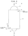
Fig. 2] Fig. 2 is a front view of a heat exchanger, as viewed from one side in a base plate stacking direction, that is used in the hydrogen gas cooling system according to the first embodiment of the present invention - [
Fig. 3] Fig. 3 is a side view of the heat exchanger illustrated inFig. 2 as viewed from the right side inFig. 2 . - [
Fig. 4] Fig. 4 is a partial cross-sectional view of a stacked body of the heat exchanger illustrated inFig. 3 . - [
Fig. 5] Fig. 5 is a schematic plan view of a first base plate that forms a first flow passage in the stacked body of the heat exchanger illustrated inFig. 3 . - [
Fig. 6] Fig. 6 is a schematic plan view of a second base plate that forms second flow passages in the stacked body of the heat exchanger illustrated inFig. 3 . - Hereinafter, embodiments of the present invention will be described with reference to the drawings.
- First, a configuration of a cooling system that is used for a hydrogen gas cooling method according to an embodiment of the present invention with reference to
Figs. 1-6 . - This cooling system is used, for example, for cooling a hydrogen gas that is supplied to a fuel cell vehicle 90 (see
Fig. 1 ) in a hydrogen station. In the hydrogen station, to enhance an efficiency of filling thefuel cell vehicle 90 with the hydrogen gas, the hydrogen gas is compressed to have a high pressure and then supplied to thefuel cell vehicle 90. In accordance with this compression of the hydrogen gas, a compression heat is generated. To avoid a temperature increase of the hydrogen gas due to this compression heat, the cooling system according to this embodiment is to cool the compressed high-pressure hydrogen gas to a low temperature before filling thefuel cell vehicle 90 with the same. - The cooling system according to this embodiment includes, as illustrated in
Fig. 1 , acooler 2, atank 4, afirst pump 6, asecond pump 8, aheat exchanger 10, acontrol unit 58, a second inflow porttemperature detection portion 60, a second feed-out porttemperature detection portion 62, and a first feed-out porttemperature detection portion 64. - The
cooler 2 is a device for cooling a brine. Thecooler 2 is configured to be capable of changing a cooling power to cool the brine. Thecooler 2 receives a control signal from thecontrol unit 58 as described below. Thecooler 2 changes the cooling power in accordance with the received control signal. In other words, when the received control signal indicates an increase of the cooling power, thecooler 2 increases the cooling power in accordance with this indication, while, when the received control signal indicates a decrease of the cooling power, thecooler 2 decreases the cooling power in accordance with this indication. The brine is a non-evaporative antifreeze. As the brine, for example, an ethylene glycol solution, a fluorinated liquid, or the like, may be used. - The
cooler 2 includes afeeding portion 2a and adischarge portion 2b. Thefeeding portion 2a is a portion into which the brine that has been subjected to heat exchange with the hydrogen gas in theheat exchanger 10 so as to have an increased temperature is fed. Thedischarge portion 2b is a portion for discharging the brine that has been cooled by thecooler 2. Thecooler 2 allows the brine that has been fed from thefeeding portion 2a into thecooler 2 to be subjected to heat exchange with a refrigerant, such as a low-temperature hydrochlorofluorocarbon, thereby cooling the brine. The cooler 2 discharges the cooled brine from thedischarge portion 2b. Thecooler 2 is configured to be capable of changing a temperature of the refrigerant. Thecooler 2 changes the temperature of the refrigerant, thereby changing the cooling power for cooling the brine. In other words, when the control signal that has been received from thecontrol unit 58 indicates an increase of the cooling power, thecooler 2 decreases the temperature of the refrigerant to increase the cooling power, while, when the control signal that has been received from thecontrol unit 58 indicates a decrease of the cooling power, thecooler 2 increases the temperature of the refrigerant to decrease the cooling power. The brine at, for example, -30°C is fed into thecooler 2. Thecooler 2 cools the brine that has been fed thereinto to, for example, -40°C or lower. - The
tank 4 stores the brine. In thetank 4, afirst reservoir chamber 12 and asecond reservoir chamber 14 are provided. Thefirst reservoir chamber 12 stores the cooled brine that has been discharged from thecooler 2. Thesecond reservoir chamber 14 stores the brine that has been subjected to heat exchange and discharged from theheat exchanger 10. - The
first reservoir chamber 12 is connected through apipe 18 to thedischarge portion 2b of thecooler 2, while connected through apipe 20 to asupply header 28, as described below, of theheat exchanger 10. Thesecond reservoir chamber 14 is connected through apipe 22 to adischarge header 30, as described below, of theheat exchanger 10, while connected through apipe 24 to the feedingportion 2a of thecooler 2. - A
partition wall 16 is provided between thefirst reservoir chamber 12 and thesecond reservoir chamber 14. Thispartition wall 16 prevents the brine that has been cooled and is stored in thefirst reservoir chamber 12 and the brine that has been subjected to heat exchange and is stored in thesecond reservoir chamber 14 from being mixed with each other. Moreover, thepartition wall 16 is made of a high heat-insulating material. Thepartition wall 16 prevents heat exchange between the brine stored in thefirst reservoir chamber 12 and the brine stored in thesecond reservoir chamber 14 from occurring. - The
first pump 6 is provided to thepipe 20 connected to a feed-out portion of thefirst reservoir chamber 12. Thefirst pump 6 sucks the brine stored in thefirst reservoir chamber 12 while delivering the same to theheat exchanger 10. Thisfirst pump 6 is configured to be capable of changing a flow rate of delivering the brine per unit time (hereinafter simply referred to as delivery flow rate). Thefirst pump 6 receives a control signal from thecontrol unit 58 as described below. Thefirst pump 6 changes the flow rate of delivering the brine in accordance with the received control signal. In other words, when the received control signal indicates an increase of the delivery flow rate, thefirst pump 6 increases the flow rate of delivering the brine per unit time in accordance with this indication, while, when the received control signal indicates a decrease of the delivery flow rate, thefirst pump 6 decreases the flow rate of delivering the brine per unit time in accordance with this indication. - The
second pump 8 is provided to thepipe 24 connected to a feed-out portion of thesecond reservoir chamber 14. Thesecond pump 8 sucks the brine stored in thesecond reservoir chamber 14 while delivering the same to the feedingportion 2a of thecooler 2. Thissecond pump 8 is configured to be capable of changing the flow rate of delivering the brine per unit time. - The
heat exchanger 10 allows the hydrogen gas that has been compressed by thecompressor 100 to have a high pressure to be subjected to heat exchange with the low-temperature brine, thereby cooling the hydrogen gas. Thisheat exchanger 10 includes a multitude of microchannels (fine flow passages). Theheat exchanger 10 is a so-called microchannel heat exchanger in which, while fluids are allowed to respectively flow through the microchannels, heat exchange among the fluids is performed. - The
heat exchanger 10 includes astacked body 26 in the interior of which a multitude of flow passages are provided, thesupply header 28 for supplying the brine tosecond flow passages 34, as described below, in the stackedbody 26, and thedischarge header 30 for discharging the brine from thesecond flow passages 34 as described below. - The
stacked body 26 has a rectangular parallelepiped external shape. In the interior of the stackedbody 26, a multitude offirst flow passages 32 and the multitude ofsecond flow passages 34 are provided as illustrated inFig. 4 . Each of thefirst flow passages 32 and each of thesecond flow passages 34 are microchannels (fine flow passages). Thefirst flow passages 32 allow the hydrogen gas to flow. Thesecond flow passages 34 allow the brine for cooling the hydrogen gas to flow. - The
stacked body 26 is made of a plurality offirst base plates 38, a plurality ofsecond base plates 40, and a pair ofend plates 42, as illustrated inFig. 3 . Specifically, thefirst base plates 38 and thesecond base plates 40 are alternately stacked upon one another, and upon both ends in a stacking direction thereof, the pair ofend plates 42 are separately stacked, whereby the stackedbody 26 is formed. In thestacked body 26, thesecond base plates 40 are stacked upon corresponding both sides in a thickness direction of thefirst base plates 38. The plurality offirst flow passages 32 are arranged in each of thefirst base plates 38. The plurality ofsecond flow passages 34 are arranged in each of thesecond base plates 40. Each of thebase plates base plates first base plates 38 are an example of first layers of the present invention. Thesecond base plates 40 are an example of second layers of the present invention. - In one of the plate surfaces in the thickness direction of each of the first base plates 38 (see
Fig. 5 ), a plurality of first flowpassage groove portions 48 for forming the plurality offirst flow passages 32 are formed. Note thatFig. 5 illustrates an external shape of the entirety of each of the plurality of first flowpassage groove portions 48 formed in each of thefirst base plates 38. In other words, inFig. 5 , illustration of each of the first flowpassage groove portions 48 is omitted, but, in practice, the plurality of first flowpassage groove portions 48 are arranged parallel to each other in the external shape as illustrated inFig. 5 . Openings of the plurality of first flowpassage groove portions 48 formed in the one of the plate surfaces of each of thefirst base plates 38 are sealed by one of thesecond base plates 40 that is stacked on this plate surface. The plurality of first flowpassage groove portions 48 in which these openings are sealed form the plurality offirst flow passages 32 that are arranged on one of plate surface sides of each of thefirst base plates 38 while lying along this one of the plate surfaces. - A
first inflow port 50 of each of thefirst flow passages 32 is formed at a location that is adjacent to one end of the stackedbody 26 in a longitudinal direction of the first base plates 38 (adjacent to an upper end of the stacked body 26) while adjacent to one end of the stackedbody 26 in a width direction of thefirst base plates 38. Thisfirst inflow port 50 is a portion for receiving the hydrogen gas. Thefirst inflow port 50 is made of a through hole that penetrates each of thebase plates end plates 42 at the same location in the thickness direction to communicate therewith. Thereby, thefirst inflow port 50 continues in the stacking direction of thebase plates end plates 42 at a front side. Moreover, the plurality offirst flow passages 32 formed in each of thefirst base plates 38 are all connected to thisfirst inflow port 50. In other words, thefirst inflow port 50 is a feeding port of the hydrogen gas that is common to all thefirst flow passages 32 provided in the stackedbody 26. - A first feed-out
port 52 of each of thefirst flow passages 32 is formed at a location that is adjacent to an end portion of the stackedbody 26 at a side opposite to thefirst inflow port 50 in the longitudinal direction and the width direction of thefirst base plates 38. This first feed-outport 52 is a portion for discharging the hydrogen gas that has flown through each of thefirst flow passages 32. Similarly to thefirst inflow port 50, the first feed-outport 52 is made of a through hole that penetrates each of thebase plates end plates 42 at the same location in the thickness direction to communicate therewith. Moreover, similarly to thefirst inflow port 50, the first feed-outport 52 is a discharge port of the hydrogen gas that is common to all thefirst flow passages 32 provided in the stackedbody 26. - Each of the
first flow passages 32 has a meandering shape in which a portion that linearly extends from one side to the other side in the width direction of thefirst base plates 38 and a portion folded back therefrom that linearly extends from the other side to the one side in the width direction of thefirst base plates 38 are repeatedly provided between thefirst inflow port 50 and the first feed-outport 52. - In one of plate surfaces in a thickness direction of each of the second base plates 40 (see
Fig. 6 ), a plurality of second flowpassage groove portions 54 for forming the plurality ofsecond flow passages 34 are formed. Note that, similarly toFig. 5 ,Fig. 6 illustrates an external shape of the entirety of each of the plurality of second flowpassage groove portions 54 formed in each of thesecond base plates 40. In other words, inFig. 6 , illustration of each of the second flowpassage groove portions 54 is omitted, but, in practice, the plurality of second flowpassage groove portions 54 are arranged parallel to each other in the external shape as illustrated inFig. 6 . Openings of the plurality of second flowpassage groove portions 54 formed in the one of the plate surfaces of each of thesecond base plates 40 are sealed by one of thefirst base plates 38 that is stacked on this plate surface. The plurality of second flowpassage groove portions 54 in which these openings are sealed form the plurality ofsecond flow passages 34 that are arranged on one of plate surface sides of each of thesecond base plates 40 while lying along this one of the plate surfaces. - The plurality of
second flow passages 34 formed in each of thesecond base plates 40 are separated into two lines. Specifically, these plurality ofsecond flow passages 34 are made of thesecond flow passages 34 of one group that are arranged, in view of the center in a width direction of thesecond base plates 40, on one side in the width direction thereof and thesecond flow passages 34 of the other group that are arranged, in view of the center in the width direction of thesecond base plates 40, on the other side in the width direction thereof. Each of thesecond flow passages 34 of the one group has a meandering shape in which a portion that linearly extends from a center side in the width direction of thesecond base plates 40 to an edge side on the one side in the width direction of thesecond base plates 40 and a portion folded back therefrom that linearly extends to the center side in the width direction of thesecond base plates 40 are repeatedly provided. Moreover, each of thesecond flow passages 34 of the other group has such a meandering shape as to be symmetrical to thesecond flow passages 34 of the one group with respect to the center in the width direction of thesecond base plates 40. - One end of each of the
second flow passages 34 that are formed in thesecond base plates 40 opens at an end surface on one side in a longitudinal direction of the stackedbody 26 that lies along a longitudinal direction of thesecond base plates 40, specifically at the end surface on a side on which the first feed-outport 52 is disposed. An opening of each of thesesecond flow passages 34 at the one end is asecond inflow port 34a that receives the brine. Thesecond inflow port 34a is an example of an inflow port of each of the second flow passages of the present invention. An end portion of each of thesecond flow passages 34 at a side opposite to thesecond inflow port 34a that are formed in thesecond base plates 40 opens at an end surface on the other side in the longitudinal direction of the stackedbody 26 that lies along the longitudinal direction of thesecond base plates 40, specifically at the end surface on a side on which thefirst inflow port 50 is disposed. An opening of each of thesesecond flow passages 34 at the opposite side is a second feed-outport 34b that discharges the brine that has flown through each of thesecond flow passages 34. The second feed-outport 34b is an example of a feed-out port of each of the second flow passages of the present invention. - In the
stacked body 26 configured as described above, a formation region of portions of the plurality offirst flow passages 32 arranged on one of the plate surface sides of thefirst base plates 38 that linearly extend in the width direction of thefirst base plates 38 and a formation region of portions of the plurality ofsecond flow passages 34 arranged on one of the plate surface sides of thesecond base plates 40 that linearly extend in the width direction of thesecond base plates 40 corresponds to each other in such a manner as to overlap with each other in view of the stacking direction of thebase plates first inflow port 50 and the second feed-outports 34b are positioned upward while the first feed-outport 52 and thesecond inflow ports 34a are positioned downward, and the longitudinal direction of the stacked body 26 (longitudinal direction of each of thebase plates 38, 40) corresponds to an upward/downward direction. In other words, in the stackedbody 26 of theheat exchanger 10, thefirst inflow port 50 and the first feed-outport 52 of each of thefirst flow passages 32 are disposed such that the hydrogen gas that is fed from thefirst inflow port 50 into each of thefirst flow passages 32 and flows through each of thefirst flow passages 32 toward the first feed-outport 52 generally moves from upward to downward in a vertical direction orthogonal to the stacking direction of thefirst base plates 38 and thesecond base plates 40. Meanwhile, thesecond inflow ports 34a and the second feed-outports 34b of the correspondingsecond flow passages 34 are disposed such that the brine that is fed from thesecond inflow ports 34a into the correspondingsecond flow passages 34 and flows through the correspondingsecond flow passages 34 toward the second feed-outports 34b generally moves from downward to upward in the vertical direction. - The
supply header 28 is attached to the end surface of the stackedbody 26 in which thesecond inflow ports 34a are formed. The pipe 20 (seeFig. 1 ) is connected to thesupply header 28. The brine that has been delivered from thefirst pump 6 is supplied through thepipe 20 to thesupply header 28. An interior space through which the supplied brine passes is provided in thesupply header 28. This interior space communicates with all thesecond inflow ports 34a of thesecond flow passages 34 provided in the stackedbody 26 while thesupply header 28 is attached to the stackedbody 26. In other words, the brine that has been supplied to thesupply header 28 is distributed from the interior space of thesupply header 28 to thesecond inflow ports 34a of the correspondingsecond flow passages 34 and fed thereinto. - The
discharge header 30 is attached to the end surface of the stackedbody 26 in which the second feed-outports 34b are formed. The pipe 22 (seeFig. 1 ) is connected to thedischarge header 30. An interior space is provided in thedischarge header 30. This interior space communicates with all the second feed-outports 34b of thesecond flow passages 34 provided in the stackedbody 26 while thedischarge header 30 is attached to the stackedbody 26. The brine that has flown through each of thesecond flow passages 34 flows out from the second feed-outports 34b of the correspondingsecond flow passages 34 into the interior space of thedischarge header 30, and is discharged from the interior space to thepipe 22. - Moreover, the
heat exchanger 10 of the cooling system according to this embodiment has a configuration, such as a shape, a size, and the number of theflow passages base plates stacked body 26, that is designed in such a manner as to satisfy a relationship of Formula (1) below. In Formula (1) below, an amount of heat exchange required for theheat exchanger 10 is Q (kW), an overall heat transfer coefficient that is a value relative to the configuration of theheat exchanger 10 is U (kW/m2 ·°C), a heat transfer area in theheat exchanger 10 is A (m2), and a logarithmic mean temperature determined based on the temperature of the brine at thesecond inflow ports 34a of thesecond flow passages 34 and the temperature of the brine at the second feed-outports 34b of thesecond flow passages 34 is dT (°C).
- The second inflow port temperature detection portion 60 (see
Figs. 1 and2 ) is connected to thesupply header 28. The second inflow porttemperature detection portion 60 is a detector for detecting the temperature of the brine fed into thesecond inflow ports 34a of thesecond flow passages 34. In other words, the second inflow porttemperature detection portion 60 detects the temperature of the brine at thesecond inflow ports 34a. - The second feed-out port temperature detection portion 62 (see
Figs. 1 and2 ) is connected to thedischarge header 30. The second feed-out porttemperature detection portion 62 is a detector for detecting the temperature of the brine discharged from the second feed-outports 34b of thesecond flow passages 34. In other words, the second feed-out porttemperature detection portion 62 detects the temperature of the brine at the second feed-outports 34b. - The first feed-out port temperature detection portion 64 (see
Figs. 1 and2 ) is connected to the first feed-outport 52 of thefirst flow passages 32. The first feed-out porttemperature detection portion 64 is a detector for detecting a temperature of the hydrogen gas discharged from the first feed-outport 52. In other words, the first feed-out porttemperature detection portion 64 detects the temperature of the hydrogen gas at the first feed-outport 52. - The second inflow port
temperature detection portion 60, the second feed-out porttemperature detection portion 62, and the first feed-out porttemperature detection portion 64 transmit data of detected temperatures to thecontrol unit 58 respectively. Thecontrol unit 58 controls the temperature of the brine flowing through each of thesecond flow passages 34. Based on the received data of each of the detected temperatures, thecontrol unit 58 controls an operation of thecooler 2 while controlling the flow rate of the brine delivered from thefirst pump 6, thereby controlling the temperature of the brine flowing through each of thesecond flow passages 34. Thecontrol unit 58 controls the operation of thecooler 2 while controlling the flow rate of the brine delivered from thefirst pump 6 such that the temperature of the brine at the second feed-outports 34b is higher than the temperature of the hydrogen gas at the first feed-outport 52. - Next, the hydrogen gas cooling method according to this embodiment will be described.
- In the hydrogen gas cooling method according to this embodiment, the cooling system as described above is prepared. Then, the cooler 2 (see
Fig. 1 ) allows the brine to be subjected to heat exchange with a low-temperature refrigerant, thereby cooling the brine. The cooled brine is delivered from thedischarge portion 2b through thepipe 18 to thefirst reservoir chamber 12 of thetank 4. The brine that has been fed into thefirst reservoir chamber 12 is temporarily stored in thefirst reservoir chamber 12 while discharged to thepipe 20 due to a suction force of thefirst pump 6. The brine that has been discharged to thepipe 20 is delivered by thefirst pump 6 to theheat exchanger 10, and fed through the interior space of the supply header 28 (seeFigs. 2 and3 ) into each of thesecond flow passages 34 in the stacked body 26 (seeFig. 6 ) from thesecond inflow ports 34a thereof. - Based on data of the detected temperature received from the second inflow port
temperature detection portion 60, thecontrol unit 58 controls the operation (cooling force) of thecooler 2 for cooling the brine such that the temperature of the brine at thesecond inflow ports 34a is -40°C. Specifically, thecontrol unit 58 allows thecooler 2 to adjust the temperature of the refrigerant such that the detected temperature of the second inflow porttemperature detection portion 60 is -40°C, thereby controlling the cooling force of thiscooler 2. In detail, when the detected temperature of the second inflow porttemperature detection portion 60 is above -40°C, thecontrol unit 58 transmits to thecooler 2 the control signal indicating an increase of the cooling power, and thecooler 2 that has received this control signal increases the cooling power in accordance with this control signal. Consequently, the temperature of the brine at thesecond inflow ports 34a that is detected by the second inflow porttemperature detection portion 60 decreases close to -40°C. On the other hand, when the detected temperature of the second inflow porttemperature detection portion 60 is below -40°C, thecontrol unit 58 transmits to thecooler 2 the control signal indicating a decrease of the cooling power, and thecooler 2 that has received this control signal decreases the cooling power in accordance with this control signal. Consequently, the temperature of the brine at thesecond inflow ports 34a that is detected by the second inflow porttemperature detection portion 60 increases close to -40°C. - The brine that has been fed into each of the
second flow passages 34 flows from thesecond inflow ports 34a toward the second feed-outports 34b through thesesecond flow passages 34. The brine that flows through each of thesesecond flow passages 34 generally moves from downward to upward in the vertical direction orthogonal to the stacking direction of thebase plates body 26. - Meanwhile, the compressor 100 (see
Fig. 1 ) compresses the hydrogen gas. The compressed high-pressure hydrogen gas is fed from thecompressor 100 into thefirst inflow port 50 of theheat exchanger 10. The hydrogen gas fed into thisfirst inflow port 50 is compressed in thecompressor 100 and then cooled by cooling water to have a temperature of 40°C. Then, the hydrogen gas that has been fed into thefirst inflow port 50 is distributed to each of thefirst flow passages 32 in the stacked body 26 (seeFig. 5 ) to be supplied. The hydrogen gas that has been supplied to each of thefirst flow passages 32 flows through thesefirst flow passages 32 from a side of thefirst inflow port 50 toward the first feed-outport 52, and generally moves from upward to downward in the vertical direction. In this process, heat exchange between the hydrogen gas flowing through each of the first flow passages 32 (seeFig. 4 ) and the brine flowing through thesecond flow passages 34 adjacent to these first flow passages 32 (seeFig. 4 ) is performed through a portion of the stackedbody 26 that is positioned between both theseflow passages port 52 comes to -37°C. - On the other hand, the temperature of the brine gradually increases as the brine flows toward downstream of each of the second flow passages 34 (toward the second feed-out
ports 34b). The rate of the temperature increase of the brine at this time differs depending on the temperature and the flow rate of the brine fed into thesecond flow passages 34. In this embodiment, thecontrol unit 58 controls the flow rate of delivering the brine fed into each of thesecond flow passages 34, namely the flow rate in which thefirst pump 6 delivers the brine such that the temperature of the brine at the second feed-outports 34b is higher than the temperature of the hydrogen gas at the first feed-out port 52 (-37°C) while the temperature of the brine at the second feed-outports 34b is higher by at least 10°C than the temperature of the brine at thesecond inflow ports 34a (-40°C). Specifically, thecontrol unit 58 controls the flow rate of delivering the brine through thefirst pump 6 to such a flow rate that the temperature of the brine at the second feed-outports 34b is -30°C. - At this time, the
control unit 58 controls the flow rate of delivering the brine through thefirst pump 6 based on data of the detected temperature received from the first feed-out porttemperature detection portion 64, data of the detected temperature received from the second inflow porttemperature detection portion 60, and data of the detected temperature received from the second feed-out porttemperature detection portion 62. - Specifically, when the detected temperature of the first feed-out port
temperature detection portion 64 and the detected temperature of the second feed-out porttemperature detection portion 62 are compared with each other, and the detected temperature of the second feed-out porttemperature detection portion 62 is lower than or equal to the detected temperature of the first feed-out porttemperature detection portion 64, thecontrol unit 58 allows thefirst pump 6 to decrease the flow rate of delivering the brine until the detected temperature of the second feed-out porttemperature detection portion 62 is higher than the detected temperature of the first feed-out porttemperature detection portion 64. At this time, thecontrol unit 58 transmits to thefirst pump 6 the control signal indicating a decrease of the delivery flow rate, and thefirst pump 6 decreases the flow rate of delivering the brine in accordance with the received control signal. - Meanwhile, when the detected temperature of the second feed-out port
temperature detection portion 62 is higher than the detected temperature of the second inflow porttemperature detection portion 60, and a difference in temperature between the detected temperature of the second feed-out porttemperature detection portion 62 and the detected temperature of the second inflow porttemperature detection portion 60 is less than 10°C, thecontrol unit 58 allows thefirst pump 6 to decrease the flow rate of delivering the brine until this difference in temperature is 10°C or more. Also at this time, thecontrol unit 58 transmits to thefirst pump 6 the control signal indicating a decrease of the delivery flow rate, thereby allowing thefirst pump 6 to decrease the flow rate of delivering the brine. - Meanwhile, at this time, the
control unit 58 controls the flow rate of delivering the brine through thefirst pump 6 such that the detected temperature of the second feed-out porttemperature detection portion 62 is -30°C. In other words, when the detected temperature of the second feed-out porttemperature detection portion 62 is below -30°C, thecontrol unit 58 transmits to thefirst pump 6 the control signal indicating a decrease of the delivery flow rate, and thefirst pump 6 decreases the flow rate of delivering the brine in accordance with the received control signal. Meanwhile, when the detected temperature of the second feed-out porttemperature detection portion 62 is above -30°C, thecontrol unit 58 transmits to thefirst pump 6 the control signal indicating an increase of the delivery flow rate, and thefirst pump 6 increases the flow rate of delivering the brine in accordance with the received control signal. - The hydrogen gas that has been cooled is discharged through the first feed-out
port 52 of each of the first flow passages 32 (seeFigs. 2 and5 ) and supplied to the fuel cell vehicle 90 (seeFig. 1 ). On the other hand, the brine that has been subjected to heat exchange is discharged from the second feed-outports 34b of the correspondingsecond flow passages 34 through the interior space of thedischarge header 30 to the pipe 22 (seeFig. 1 ) while fed through thispipe 22 into thesecond reservoir chamber 14 of thetank 4 and stored. The brine that has been subjected to heat exchange and is stored in thesecond reservoir chamber 14 is sucked by thesecond pump 8 through thepipe 24 while delivered to thecooler 2, and fed from the feedingportion 2a thereof into thecooler 2. The brine that has been subjected to heat exchange and is fed into thecooler 2 is cooled again and supplied from thecooler 2 to theheat exchanger 10. - In the manner as described above, the hydrogen gas cooling method according to this embodiment is performed.
- In this embodiment, the hydrogen gas is cooled through heat exchange in the stacked
body 26 of theheat exchanger 10 between the hydrogen gas flowing through each of thefirst flow passages 32 that are microchannels and the brine flowing through each of thesecond flow passages 34 that are microchannels. Accordingly, a heat transfer efficiency of the hydrogen gas per unit volume of the brine is enhanced so that a hydrogen gas cooling efficiency can be enhanced. - Moreover, the temperature of the hydrogen gas flowing through the
first flow passages 32 decreases as the hydrogen gas flows downstream, and the temperature of the brine flowing through thesecond flow passages 34 increases as the brine flows downstream, namely toward thefirst inflow port 50 of thefirst flow passages 32. In this embodiment, the hydrogen gas flowing through each of thefirst flow passages 32 generally moves from upward to downward while the brine flowing through each of thesecond flow passages 34 generally moves from downward to upward so that, as the hydrogen gas flows downstream of thefirst flow passages 32, the hydrogen gas is allowed to be subjected to heat exchange with the further low-temperature brine upstream of thesecond flow passages 34. Thus, the hydrogen gas cooling efficiency can be further enhanced. - Further, in this embodiment, the temperature and the flow rate of the brine fed into each of the
second flow passages 34 are controlled such that the temperature of the brine at the second feed-outports 34b of thesecond flow passages 34 is higher than the temperature of the hydrogen gas at the first feed-outport 52 of thefirst flow passages 32. Accordingly, compared with a case in which the temperature of the brine at the second feed-outports 34b of thesecond flow passages 34 is lower than or equal to the temperature of the hydrogen gas at the first feed-outport 52 of thefirst flow passages 32, cold heat per brine flow rate (unit volume) that is provided from the brine to the hydrogen gas in theheat exchanger 10 is greater so that the hydrogen gas can be further effectively cooled. - As described above, in this embodiment, the hydrogen gas cooling efficiency can be enhanced so that, even if an amount of use of the brine is reduced, or if the brine is not excessively cooled to a low temperature, the hydrogen gas can be sufficiently cooled.
- Moreover, in this embodiment, the multitude of
first flow passages 32 that are microchannels and the multitude ofsecond flow passages 34 that are microchannels can be accumulated in the stackedbody 26 of theheat exchanger 10. Accordingly, theheat exchanger 10 is designed to be downsized while an amount of hydrogen gas cooling treatment can be sufficiently ensured. - Thus, in this embodiment, an amount of use of the brine that is used for cooling the hydrogen gas is reduced, an increase of an energy required for cooling the brine in the cooler 2 (energy required for cooling the refrigerant) can be suppressed and the hydrogen gas can be sufficiently cooled, while the
heat exchanger 10 is downsized and, at the same time, an amount of hydrogen gas cooling treatment is ensured. Moreover, in this embodiment, an amount of use of the brine can be reduced, whereby an energy required for driving thefirst pump 6 and thesecond pump 8 for circulating the brine between thecooler 2 and theheat exchanger 10 can be reduced. - Moreover, in this embodiment, each of the
first flow passages 32 and each of thesecond flow passages 34 are formed to have a meandering shape. Accordingly, compared with a case in which, for example, these flow passages are formed to have a linear shape, the number of theflow passages base plates flow passages first flow passages 32 and thesecond flow passages 34 in the stackedbody 26 can be sufficiently ensured. Moreover, the number of theflow passages base plates flow passages flow passages first flow passages 32 and thesecond flow passages 34 can be sufficiently ensured, increasing the velocity of flow of the hydrogen gas flowing through each of thefirst flow passages 32 and the velocity of flow of the brine flowing through each of thesecond flow passages 34 allows the heat transfer performance between these hydrogen gas and brine to improve. Thus, the hydrogen gas can be further effectively cooled. - Moreover, in this embodiment, the flow rate of the brine fed into each of the
second flow passages 34 is controlled such that the temperature of the brine at the second feed-outports 34b of thesecond flow passages 34 is higher by at least 10°C than the temperature of the brine at thesecond inflow ports 34a of thesecond flow passages 34. Accordingly, the cold heat that is provided from the brine flowing through thesecond flow passages 34 to the hydrogen gas flowing through thefirst flow passages 32 in theheat exchanger 10 can be sufficiently magnified. Consequently, the hydrogen gas cooling efficiency can be further enhanced. - Moreover, in this embodiment, the temperature of the brine fed into each of the
second flow passages 34 is controlled such that the temperature of the brine at thesecond inflow ports 34a of thesecond flow passages 34 is -40°C. Accordingly, while hydrogen embrittlement of the stackedbody 26 of theheat exchanger 10 is suppressed, the hydrogen gas can be sufficiently cooled. Specifically, it is known that if stainless steel that is a material of each of thebase plates stacked body 26 is in contact with a hydrogen gas while cooled to a low temperature below -40°C, hydrogen embrittlement becomes remarkable. Thus, as in this embodiment, the temperature of the brine fed into each of thesecond flow passages 34 is controlled such that the temperature of the brine at thesecond inflow ports 34a is -40°C, whereby the temperature of the stackedbody 26 is -40°C or more and hydrogen embrittlement can be suppressed. Moreover, the brine of -40°C is fed into thesecond inflow ports 34a, whereby hydrogen embrittlement of the stackedbody 26 can be suppressed while the hydrogen gas flowing through thefirst flow passages 32 can be sufficiently cooled. - Note that it should be understood that the embodiment disclosed herein is exemplary and not restrictive in all aspects. The scope of the present invention is defined not by the description of the above embodiment but by the claims, and includes equivalents of the claims and all modifications within the scope of the claims.
- For example, as shapes of the first flow passages and the second flow passages, various shapes other than the above-described shape can be applied. For example, the first flow passages and the second flow passages are not limited to passages having a meandering shape in which folding backs are repeated as described above, but may be passages that linearly extend.
- Moreover, the number of the first flow passages formed per first base plate and the number of the second flow passages formed per second base plate may be optionally determined. Moreover, the width and the cross-sectional shape of each of the first flow passages and the width and the cross-sectional shape of each of the second flow passages may be optionally determined.
- Moreover, in the embodiment as described above, the first base plates in which the first flow passages are arranged and the second base plates in which the second flow passages are arranged are alternately stacked upon one another, to which the configuration of stacking layers is not limited. For example, two or more sheets of the second base plates in which the second flow passages that allow the brine to flow therethrough may be stacked upon one sheet of the first base plates in which the first flow passages that allow the hydrogen gas to flow therethrough.
- Moreover, directions of the arrangement of the heat exchanger (stacked body) are not limited to the direction in which the longitudinal direction of the base plates corresponds to the upward/downward direction as described above. For example, the heat exchanger (stacked body) may be arranged in a direction in which the longitudinal direction of the base plates corresponds to the horizontal direction, otherwise in a slanted direction.
- The embodiment as described above is summarized as below.
- The hydrogen gas cooling method according to the above-described embodiment is a hydrogen gas cooling method using a brine that is a non-evaporative antifreeze, the method including: a preparation step of preparing a heat exchanger including a stacked body in which a first layer in which a plurality of first flow passages that are fine flow passages are arranged and a second layer in which a plurality of second flow passages that are fine flow passages are arranged are stacked upon one another; and a cooling step in which a hydrogen gas is allowed to flow through each of the first flow passages while a brine having a temperature lower than the hydrogen gas is allowed to flow through each of the second flow passages to perform heat exchange between the hydrogen gas flowing through the first flow passages and the brine flowing through the second flow passages, thereby cooling the hydrogen gas, in which, in the cooling step, the hydrogen gas is allowed to flow through each of the first flow passages such that the hydrogen gas flowing through each of the first flow passages moves from one side to the other side in a particular direction orthogonal to a stacking direction of the first layer and the second layer while the brine is allowed to flow through each of the second flow passages such that the brine flowing through each of the second flow passages moves from the other side to the one side in the particular direction, and a temperature and a flow rate of the brine fed into each of the second flow passages are controlled such that the temperature of the brine at a feed-out port of the second flow passages is higher than a temperature of the hydrogen gas at a feed-out port of the first flow passages.
- In this hydrogen gas cooling method, the hydrogen gas is cooled through heat exchange in the stacked body of the heat exchanger between the hydrogen gas flowing through each of the first flow passages that are fine flow passages and the brine flowing through each of the second flow passages that are fine flow passages. Compared with conventional hydrogen gas cooling methods using heat exchange through a heat transfer medium filled into the filled bath and conventional hydrogen gas cooling methods using heat exchange between a refrigerant and a hydrogen gas in a dual pipe, a heat transfer efficiency of the hydrogen gas per unit volume of the brine is enhanced. Consequently, a hydrogen gas cooling efficiency per unit volume of the brine can be enhanced.
- Moreover, the temperature of the hydrogen gas flowing through the first flow passages decreases as the hydrogen gas flows downstream, and the temperature of the brine flowing through the second flow passages increases as the brine flows downstream, namely toward the hydrogen gas inflow port of the first flow passages. In this hydrogen gas cooling method, the hydrogen gas is fed into each of the first flow passages and the brine is fed into each of the second flow passages such that the hydrogen gas flowing through each of the first flow passages moves from one side to the other side in a particular direction orthogonal to a stacking direction of each of the layers of the stacked body while the brine flowing through each of the second flow passages moves from the other side to the one side. Accordingly, as the hydrogen gas flows downstream through the first flow passages, the hydrogen gas is allowed to be subjected to heat exchange with the further low-temperature brine upstream of the second flow passages. Thus, the hydrogen gas cooling efficiency can be further enhanced.
- Further, in this hydrogen gas cooling method, the temperature and the flow rate of the brine fed into each of the second flow passages are controlled such that the temperature of the brine at the feed-out port of the second flow passages is higher than the temperature of the hydrogen gas at the feed-out port of the first flow passages. Accordingly, compared with a case in which the temperature of the brine at the feed-out port of the second flow passages is lower than or equal to the temperature of the hydrogen gas at the feed-out port of the first flow passages, cold heat per brine flow rate (unit volume) that is provided from the brine to the hydrogen gas is greater. Consequently, the hydrogen gas can be further effectively cooled.
- As described above, in this cooling method, the hydrogen gas cooling efficiency can be enhanced so that, even if an amount of use of the brine is reduced, or if the brine is not excessively cooled to a low temperature, the hydrogen gas can be sufficiently cooled.
- Moreover, in this cooling method, the plurality of first flow passages that are fine flow passages and the plurality of second flow passages that are fine flow passages can be accumulated in the stacked body of the heat exchanger. Accordingly, the heat exchanger is designed to be downsized while an amount of hydrogen gas cooling treatment can be sufficiently ensured. Thus, in this cooling method, an amount of use of the brine that is used for cooling the hydrogen gas is reduced, an increase of an energy required for cooling the brine can be suppressed and the hydrogen gas can be sufficiently cooled, while the heat exchanger is downsized and, at the same time, an amount of hydrogen gas cooling treatment is ensured.
- In the hydrogen gas cooling method as described above, preferably, in the preparation step of preparing, as the heat exchanger, a heat exchanger including, as the stacked body, a stacked body in an interior of which each of the first flow passages and each of the second flow passages are formed to each have a meandering shape, and in the cooling step, the hydrogen gas is allowed to flow along the meandering shape of each of the first flow passages through each of the first flow passages, and the brine is allowed to flow along the meandering shape of each of the second flow passages through each of the second flow passages.
- According to this configuration, compared with a case in which, for example, the flow passages are formed to have a linear shape, the number of the flow passages provided per layer becomes small, but the length of each of the flow passages can be lengthened. Accordingly, a heat transfer area of the first flow passages and the second flow passages in the stacked body can be sufficiently ensured. Moreover, the number of the flow passages provided per layer becomes small, whereby, even when total flow rates of fluids allowed to flow through these flow passages are the same, the velocity of flow of the fluids flowing through each of the flow passages, respectively, can be increased. Generally, if the velocity of flow of a fluid flowing through a flow passage increases, the turbulence of the fluid in the flow passage increases and consequently a heat transfer performance improves. Thus, in this configuration, while the heat transfer area of the first flow passages and the second flow passages can be sufficiently ensured, increasing the velocity of flow of the hydrogen gas flowing through each of the first flow passages and the velocity of flow of the brine flowing through each of the second flow passages allows the heat transfer performance between these hydrogen gas and brine to improve, and the hydrogen gas can be further effectively cooled.
- In the hydrogen gas cooling method as described above, preferably, in the cooling step, the flow rate of the brine fed into each of the second flow passages is controlled such that the temperature of the brine at the feed-out port of the second flow passages is higher by at least 10°C than the temperature of the brine at an inflow port of the second flow passages.
- According to this configuration, a specific condition of the feeding flow rate of the brine into each of the second flow passages in which the cold heat that is provided from the brine flowing through the second flow passages to the hydrogen gas flowing through the first flow passages in the stacked body of the heat exchanger can be sufficiently magnified can be set.
- In the hydrogen gas cooling method as described above, preferably, in the cooling step, the temperature of the brine fed into each of the second flow passages is controlled such that the temperature of the brine at the inflow port of the second flow passages is -40°C.
- According to this configuration, a temperature condition of the brine fed into each of the second flow passages in which while hydrogen embrittlement of the stacked body of the heat exchanger is suppressed, the hydrogen gas can be effectively cooled can be set.
- The hydrogen gas cooling system according to the embodiment as described above is a hydrogen gas cooling system using a brine that is a non-evaporative antifreeze, preferably, the system including: a cooler that cools the brine; a heat exchanger that is connected to the cooler such that the brine circulates between the heat exchanger and the cooler, and allows a hydrogen gas to be subjected to heat exchange with the brine supplied from the cooler, thereby cooling the hydrogen gas; a pump that delivers the brine that has been cooled by the cooler from the cooler to the heat exchanger; and a control unit that controls a temperature of the brine, in which the heat exchanger includes a stacked body in which a first layer in which a plurality of first flow passages that are fine flow passages into which the hydrogen gas is fed and flows therethrough are arranged and a second layer in which a plurality of second flow passages that are fine flow passages into which the brine is fed and flows therethrough are arranged are stacked upon one another, and allows heat exchange between the hydrogen gas flowing through the first flow passages and the brine flowing through the second flow passages to be performed, each of the first flow passages includes a first inflow port that receives the hydrogen gas and a first feed-out port that discharges the hydrogen gas, and the first inflow port and the first feed-out port are disposed such that the hydrogen gas that is fed from the first inflow port into the first flow passages and flows through the first flow passages toward the first feed-out port moves from one side to the other side in a particular direction orthogonal to a stacking direction of the first layer and the second layer, each of the second flow passages includes a second inflow port that receives the brine and a second feed-out port that discharges the brine, and the second inflow port and the second feed-out port are disposed such that the brine that is fed from the second inflow port into the second flow passages and flows through the second flow passages toward the second feed-out port moves from the other side to the one side in the particular direction, and the control unit controls an operation of the cooler and a flow rate of the brine that the pump delivers, such that the temperature of the brine at the second feed-out port is higher than a temperature of the hydrogen gas at the first feed-out port.
- In this hydrogen gas cooling system, similarly to the hydrogen gas cooling method as described above, an amount of use of the brine that is used for cooling the hydrogen gas is reduced, an increase of an energy required for cooling the brine can be suppressed and the hydrogen gas can be sufficiently cooled, while the heat exchanger is downsized and, at the same time, an amount of hydrogen gas cooling treatment is ensured.
- Preferably, the hydrogen gas cooling system as described above further includes: a first feed-out port temperature detection portion that detects the temperature of the hydrogen gas at the first feed-out port; and a second feed-out port temperature detection portion that detects the temperature of the brine at the second feed-out port, in which based on the temperature detected by the first feed-out port temperature detection portion and the temperature detected by the second feed-out port temperature detection portion, the control unit controls the flow rate of the brine that the pump delivers.
- In the hydrogen gas cooling system as described above, preferably, each of the first flow passages and each of the second flow passages are formed in the stacked body to each have a meandering shape.
- According to this configuration, compared with a case in which, for example, the flow passages are formed to have a linear shape, the number of the flow passages provided per layer becomes small, but the length of each of the flow passages can be lengthened, and a heat transfer area of the first flow passages and the second flow passages in the stacked body can be sufficiently ensured. Moreover, the number of the flow passages provided per layer becomes small, whereby, even when total flow rates of fluids allowed to flow through these flow passages are the same, the velocity of flow of the fluids flowing through each of the flow passages, respectively, can be increased. Generally, if the velocity of flow of a fluid flowing through a flow passage increases, the turbulence of the fluid in the flow passage increases and consequently a heat transfer performance improves. Thus, in this configuration, while the heat transfer area of the first flow passages and the second flow passages can be sufficiently ensured, increasing the velocity of flow of the hydrogen gas flowing through each of the first flow passages and the velocity of flow of the brine flowing through each of the second flow passages allows the heat transfer performance between these hydrogen gas and brine to improve, and the hydrogen gas can be further effectively cooled.
- In the hydrogen gas cooling system as described above, preferably, the control unit allows the pump to deliver the brine such that the brine flows through each of the second flow passages at such flow rate that the temperature of the brine at the second feed-out port is higher by at least 10°C than the temperature of the brine at the second inflow port.
- According to this configuration, a flow rate of delivering the brine through the pump in which the cold heat that is provided from the brine flowing through the second flow passages to the hydrogen gas flowing through the first flow passages in the stacked body of the heat exchanger can be sufficiently magnified can be specifically set.
- In the hydrogen gas cooling system as described above, preferably, the control unit controls a cooling force of the cooler such that the temperature of the brine at the inflow port of the second flow passages is -40°C.
- According to this configuration, a temperature of cooling the brine through the cooler in which while hydrogen embrittlement of the stacked body of the heat exchanger is suppressed, the hydrogen gas can be effectively cooled can be specifically set.
- As described above, according to the embodiment as described above, an amount of use of the brine that is used for cooling the hydrogen gas is reduced, an increase of an energy required for cooling the brine can be suppressed and the hydrogen gas can be sufficiently cooled, while the heat exchanger is downsized and, at the same time, an amount of hydrogen gas cooling treatment is ensured.
Claims (7)
- A hydrogen gas cooling method using a brine that is a non-evaporative antifreeze, the method comprising:a preparation step of preparing a heat exchanger including a stacked body in which a first layer in which a plurality of first flow passages that are fine flow passages are arranged and a second layer in which a plurality of second flow passages that are fine flow passages are arranged are stacked upon one another; anda cooling step in which a hydrogen gas is allowed to flow through each of the first flow passages while a brine having a temperature lower than the hydrogen gas is allowed to flow through each of the second flow passages to perform heat exchange between the hydrogen gas flowing through the first flow passages and the brine flowing through the second flow passages, thereby cooling the hydrogen gas, whereinin the cooling step, the hydrogen gas is allowed to flow through each of the first flow passages such that the hydrogen gas flowing through each of the first flow passages moves from one side to the other side in a particular direction orthogonal to a stacking direction of the first layer and the second layer while the brine is allowed to flow through each of the second flow passages such that the brine flowing through each of the second flow passages moves from the other side to the one side in the particular direction, and a temperature and a flow rate of the brine fed into each of the second flow passages are controlled such that the temperature of the brine at a feed-out port of the second flow passages is higher than a temperature of the hydrogen gas at a feed-out port of the first flow passages.
- The hydrogen gas cooling method according to claim 1, wherein
in the preparation step of preparing, as the heat exchanger, a heat exchanger including, as the stacked body, a stacked body in an interior of which each of the first flow passages and each of the second flow passages are formed to each have a meandering shape, and
in the cooling step, the hydrogen gas is allowed to flow along the meandering shape of each of the first flow passages through each of the first flow passages, and the brine is allowed to flow along the meandering shape of each of the second flow passages through each of the second flow passages. - The hydrogen gas cooling method according to claim 1, wherein
in the cooling step, the flow rate of the brine fed into each of the second flow passages is controlled such that the temperature of the brine at the feed-out port of the second flow passages is higher by at least 10°C than the temperature of the brine at an inflow port of the second flow passages. - A hydrogen gas cooling system using a brine that is a non-evaporative antifreeze, the system comprising:a cooler that cools the brine;a heat exchanger that is connected to the cooler such that the brine circulates between the heat exchanger and the cooler, and allows a hydrogen gas to be subjected to heat exchange with the brine supplied from the cooler, thereby cooling the hydrogen gas;a pump that delivers the brine that has been cooled by the cooler from the cooler to the heat exchanger; anda control unit that controls a temperature of the brine, whereinthe heat exchanger includes a stacked body in which a first layer in which a plurality of first flow passages that are fine flow passages into which the hydrogen gas is fed and flows therethrough are arranged and a second layer in which a plurality of second flow passages that are fine flow passages into which the brine is fed and flows therethrough are arranged are stacked upon one another, and allows heat exchange between the hydrogen gas flowing through the first flow passages and the brine flowing through the second flow passages to be performed,each of the first flow passages includes a first inflow port that receives the hydrogen gas and a first feed-out port that discharges the hydrogen gas, and the first inflow port and the first feed-out port are disposed such that the hydrogen gas that is fed from the first inflow port into the first flow passages and flows through the first flow passages toward the first feed-out port moves from one side to the other side in a particular direction orthogonal to a stacking direction of the first layer and the second layer,each of the second flow passages includes a second inflow port that receives the brine and a second feed-out port that discharges the brine, and the second inflow port and the second feed-out port are disposed such that the brine that is fed from the second inflow port into the second flow passages and flows through the second flow passages toward the second feed-out port moves from the other side to the one side in the particular direction, andthe control unit controls an operation of the cooler and a flow rate of the brine that the pump delivers, such that the temperature of the brine at the second feed-out port is higher than a temperature of the hydrogen gas at the first feed-out port.
- The hydrogen gas cooling system according to claim 4, further comprising:a first feed-out port temperature detection portion that detects the temperature of the hydrogen gas at the first feed-out port; anda second feed-out port temperature detection portion that detects the temperature of the brine at the second feed-out port, whereinbased on the temperature detected by the first feed-out port temperature detection portion and the temperature detected by the second feed-out port temperature detection portion, the control unit controls the flow rate of the brine that the pump delivers.
- The hydrogen gas cooling system according to claim 4, wherein
each of the first flow passages and each of the second flow passages are formed in the stacked body to each have a meandering shape. - The hydrogen gas cooling system according to claim 4, wherein
the control unit allows the pump to deliver the brine such that the brine flows through each of the second flow passages at such flow rate that the temperature of the brine at the second feed-out port is higher by at least 10°C than the temperature of the brine at the second inflow port.
Applications Claiming Priority (2)
| Application Number | Priority Date | Filing Date | Title |
|---|---|---|---|
| JP2013159513A JP2015031420A (en) | 2013-07-31 | 2013-07-31 | Hydrogen gas cooling method and hydrogen gas cooling system |
| PCT/JP2014/069030 WO2015016076A1 (en) | 2013-07-31 | 2014-07-17 | Hydrogen gas cooling method and hydrogen gas cooling system |
Publications (3)
| Publication Number | Publication Date |
|---|---|
| EP3029406A1 true EP3029406A1 (en) | 2016-06-08 |
| EP3029406A4 EP3029406A4 (en) | 2017-04-12 |
| EP3029406B1 EP3029406B1 (en) | 2018-02-21 |
Family
ID=52431616
Family Applications (1)
| Application Number | Title | Priority Date | Filing Date |
|---|---|---|---|
| EP14831952.8A Active EP3029406B1 (en) | 2013-07-31 | 2014-07-17 | Hydrogen gas cooling method and hydrogen gas cooling system |
Country Status (5)
| Country | Link |
|---|---|
| US (1) | US20160131434A1 (en) |
| EP (1) | EP3029406B1 (en) |
| JP (1) | JP2015031420A (en) |
| KR (1) | KR20160025589A (en) |
| WO (1) | WO2015016076A1 (en) |
Cited By (2)
| Publication number | Priority date | Publication date | Assignee | Title |
|---|---|---|---|---|
| EP3677866A4 (en) * | 2017-08-29 | 2021-03-17 | Welcon Inc. | HEAT EXCHANGER |
| DE102020101528A1 (en) | 2020-01-23 | 2021-07-29 | Audi Aktiengesellschaft | Fuel cell device and motor vehicle with a fuel cell device |
Families Citing this family (19)
| Publication number | Priority date | Publication date | Assignee | Title |
|---|---|---|---|---|
| JP2016217468A (en) * | 2015-05-21 | 2016-12-22 | 日立オートモティブシステムズメジャメント株式会社 | Hydrogen gas filling device |
| JP6539533B2 (en) * | 2015-07-30 | 2019-07-03 | 株式会社神戸製鋼所 | Hydrogen gas supply method and hydrogen station |
| JP6660693B2 (en) * | 2015-09-14 | 2020-03-11 | トキコシステムソリューションズ株式会社 | Hydrogen gas filling equipment |
| JP6643105B2 (en) * | 2016-01-22 | 2020-02-12 | 伸和コントロールズ株式会社 | Cooling hydrogen supply station and hydrogen cooling device |
| JP6757150B2 (en) * | 2016-03-17 | 2020-09-16 | 株式会社神戸製鋼所 | Method of heating fluid by laminated fluid warmer and laminated fluid warmer |
| JP6738642B2 (en) * | 2016-04-13 | 2020-08-12 | 美浜株式会社 | System that combines gas supply equipment and cooling equipment |
| JP2019086278A (en) * | 2017-11-03 | 2019-06-06 | ドゥサン ヘヴィー インダストリーズ アンド コンストラクション カンパニー リミテッド | Printed circuit board-type heat exchanger having integral structure |
| US10809007B2 (en) | 2017-11-17 | 2020-10-20 | General Electric Company | Contoured wall heat exchanger |
| KR102031978B1 (en) * | 2017-12-21 | 2019-10-14 | 두산중공업 주식회사 | Printed Circuit Type Heat Exchanger Having Gas-Liquid Separating Structure |
| JP6810101B2 (en) * | 2018-06-06 | 2021-01-06 | 株式会社神戸製鋼所 | Laminated heat exchanger |
| US11333448B2 (en) | 2018-09-18 | 2022-05-17 | Doosan Heavy Industries & Construction Co., Ltd. | Printed circuit heat exchanger and heat exchange device including the same |
| JP6957029B2 (en) * | 2018-10-16 | 2021-11-02 | オリオン機械株式会社 | Plate heat exchanger manufacturing method |
| KR102271875B1 (en) | 2019-08-23 | 2021-07-01 | 한국가스공사 | Cooling apparatus for charging hydrogen and method for charging hydrogen vehicle using same |
| KR102811674B1 (en) | 2019-12-20 | 2025-05-22 | 세인트-고바인 세라믹스 앤드 플라스틱스, 인크. | Device comprising an electrochemical device and a heat exchanger |
| US12006870B2 (en) | 2020-12-10 | 2024-06-11 | General Electric Company | Heat exchanger for an aircraft |
| JP2024099428A (en) * | 2023-01-12 | 2024-07-25 | 株式会社神戸製鋼所 | Microchannel Heat Exchanger |
| DE102023124126A1 (en) * | 2023-09-07 | 2025-03-13 | Schaeffler Technologies AG & Co. KG | Stack of electrochemical cells and plate-shaped element of a cell stack |
| EP4621334A1 (en) * | 2024-03-21 | 2025-09-24 | Alfa Laval Vicarb | Heat exchanger core for a printed circuit heat exchanger and printed circuit heat exchanger |
| EP4621335A1 (en) * | 2024-03-21 | 2025-09-24 | Alfa Laval Vicarb | Printed circuit heat exchanger |
Family Cites Families (16)
| Publication number | Priority date | Publication date | Assignee | Title |
|---|---|---|---|---|
| US1662870A (en) * | 1924-10-09 | 1928-03-20 | Stancliffe Engineering Corp | Grooved-plate heat interchanger |
| US4523638A (en) * | 1979-10-01 | 1985-06-18 | Rockwell International Corporation | Internally manifolded unibody plate for a plate/fin-type heat exchanger |
| US4543978A (en) * | 1983-07-25 | 1985-10-01 | Chicago Bridge & Iron Company | Single tank for dual thermal energy storage with internal movable partition |
| US4714175A (en) * | 1986-12-01 | 1987-12-22 | Cbi Industries, Inc. | Tank liquid interface separation deck with leveling lines |
| JP3858484B2 (en) * | 1998-11-24 | 2006-12-13 | 松下電器産業株式会社 | Laminate heat exchanger |
| JP3922088B2 (en) * | 2002-05-15 | 2007-05-30 | 松下電器産業株式会社 | Heat exchanger |
| JP2004116619A (en) * | 2002-09-25 | 2004-04-15 | Nippon Sanso Corp | Fuel filling apparatus and method |
| JP2005282951A (en) * | 2004-03-30 | 2005-10-13 | Institute Of Tsukuba Liaison Co Ltd | Integrated laminated heat exchanger |
| US20100015483A1 (en) * | 2004-09-03 | 2010-01-21 | Yang Jefferson Ys | Reaction gas temperature and humidity regulating module for fuel cell stack |
| KR101256076B1 (en) * | 2006-01-06 | 2013-04-18 | 삼성에스디아이 주식회사 | Heat exchanger of plate type and fuel cell system with the same |
| JP2008128574A (en) * | 2006-11-21 | 2008-06-05 | Toshiba Corp | Heat exchanger |
| JP2008164177A (en) * | 2006-12-27 | 2008-07-17 | Taiyo Nippon Sanso Corp | Heat exchanger |
| US20100006256A1 (en) * | 2006-12-19 | 2010-01-14 | Toshiaki Kuwano | Heat exchanger |
| JP5349917B2 (en) * | 2008-11-17 | 2013-11-20 | 日本エア・リキード株式会社 | Heat exchanger used for high-pressure gas filling device, high-pressure gas filling device using the same, and high-pressure gas filling method |
| JP2011080495A (en) * | 2009-10-05 | 2011-04-21 | National Institute Of Advanced Industrial Science & Technology | Hydrogen heat exchanger for hydrogen filling system |
| JP6215539B2 (en) * | 2013-02-06 | 2017-10-18 | 株式会社神戸製鋼所 | Heat exchanger |
-
2013
- 2013-07-31 JP JP2013159513A patent/JP2015031420A/en active Pending
-
2014
- 2014-07-17 KR KR1020167002312A patent/KR20160025589A/en not_active Ceased
- 2014-07-17 WO PCT/JP2014/069030 patent/WO2015016076A1/en not_active Ceased
- 2014-07-17 EP EP14831952.8A patent/EP3029406B1/en active Active
- 2014-07-17 US US14/890,562 patent/US20160131434A1/en not_active Abandoned
Cited By (3)
| Publication number | Priority date | Publication date | Assignee | Title |
|---|---|---|---|---|
| EP3677866A4 (en) * | 2017-08-29 | 2021-03-17 | Welcon Inc. | HEAT EXCHANGER |
| US11384992B2 (en) | 2017-08-29 | 2022-07-12 | Welcon Inc. | Heat exchanger |
| DE102020101528A1 (en) | 2020-01-23 | 2021-07-29 | Audi Aktiengesellschaft | Fuel cell device and motor vehicle with a fuel cell device |
Also Published As
| Publication number | Publication date |
|---|---|
| US20160131434A1 (en) | 2016-05-12 |
| KR20160025589A (en) | 2016-03-08 |
| EP3029406A4 (en) | 2017-04-12 |
| EP3029406B1 (en) | 2018-02-21 |
| JP2015031420A (en) | 2015-02-16 |
| WO2015016076A1 (en) | 2015-02-05 |
Similar Documents
| Publication | Publication Date | Title |
|---|---|---|
| EP3029406B1 (en) | Hydrogen gas cooling method and hydrogen gas cooling system | |
| JP6368396B2 (en) | Hydrogen gas cooling method and hydrogen gas cooling system | |
| US9638471B2 (en) | Balanced heat exchanger systems and methods | |
| CN102414908B (en) | Battery system, battery module and method for cooling battery module | |
| KR101125587B1 (en) | Battery Systems, Battery Module, and Method for Cooling A Battery Module | |
| US9196935B2 (en) | Micro-channel cooling fin design based on an equivalent temperature gradient | |
| CN102374705B (en) | Evaporator with cool storage function | |
| EP2426777B1 (en) | Battery system, battery module and method for cooling the battery module | |
| US20150338168A1 (en) | Heat exchanger | |
| JP5943619B2 (en) | Laminated heat exchanger and heat exchange system | |
| EP3537088A1 (en) | Low refrigerant charge microchannel heat exchanger | |
| CN111051805A (en) | Heat Exchanger | |
| US20150041110A1 (en) | Plate heat exchanger and refrigeration cycle apparatus including the same | |
| EP2568789A1 (en) | Heat exchanger | |
| EP3370027B1 (en) | Extruded aluminum flat multi-hole tube and heat exchanger | |
| US10337808B2 (en) | Condenser | |
| EP3026753A1 (en) | Vehicle cooling device, vehicle drive battery cooling assembly and method for manufacturing a vehicle cooling device | |
| EP3199903B1 (en) | Heat exchanger and heat exchange method | |
| EP2336702A1 (en) | Refrigerant evaporator and air-conditioning device utilizing the same | |
| CN105229394B (en) | Refrigerant evaporator | |
| JP2016117010A (en) | Liquid circulation device and operation method therefor | |
| EP3775722B1 (en) | Integrated separator and distributor | |
| CN110017633B (en) | Condenser ballast with channel | |
| CN218237930U (en) | Oil-gas separation device for flooded refrigerating system | |
| CN105221236B (en) | Radiator in vehicle |
Legal Events
| Date | Code | Title | Description |
|---|---|---|---|
| PUAI | Public reference made under article 153(3) epc to a published international application that has entered the european phase |
Free format text: ORIGINAL CODE: 0009012 |
|
| 17P | Request for examination filed |
Effective date: 20151125 |
|
| AK | Designated contracting states |
Kind code of ref document: A1 Designated state(s): AL AT BE BG CH CY CZ DE DK EE ES FI FR GB GR HR HU IE IS IT LI LT LU LV MC MK MT NL NO PL PT RO RS SE SI SK SM TR |
|
| AX | Request for extension of the european patent |
Extension state: BA ME |
|
| DAX | Request for extension of the european patent (deleted) | ||
| A4 | Supplementary search report drawn up and despatched |
Effective date: 20170315 |
|
| RIC1 | Information provided on ipc code assigned before grant |
Ipc: F17C 5/06 20060101ALI20170309BHEP Ipc: H01M 8/06 20160101ALI20170309BHEP Ipc: F28F 3/08 20060101AFI20170309BHEP Ipc: F17C 13/00 20060101ALI20170309BHEP Ipc: F28F 7/02 20060101ALI20170309BHEP Ipc: F28D 9/00 20060101ALI20170309BHEP |
|
| RIC1 | Information provided on ipc code assigned before grant |
Ipc: F28F 7/02 20060101ALI20170630BHEP Ipc: F17C 5/06 20060101ALI20170630BHEP Ipc: F28D 9/00 20060101ALI20170630BHEP Ipc: F02M 21/02 20060101ALI20170630BHEP Ipc: H01M 8/06 20160101ALI20170630BHEP Ipc: F28F 3/08 20060101AFI20170630BHEP Ipc: H01M 8/04007 20160101ALI20170630BHEP Ipc: F17C 13/00 20060101ALI20170630BHEP |
|
| GRAP | Despatch of communication of intention to grant a patent |
Free format text: ORIGINAL CODE: EPIDOSNIGR1 |
|
| INTG | Intention to grant announced |
Effective date: 20170915 |
|
| GRAS | Grant fee paid |
Free format text: ORIGINAL CODE: EPIDOSNIGR3 |
|
| GRAA | (expected) grant |
Free format text: ORIGINAL CODE: 0009210 |
|
| AK | Designated contracting states |
Kind code of ref document: B1 Designated state(s): AL AT BE BG CH CY CZ DE DK EE ES FI FR GB GR HR HU IE IS IT LI LT LU LV MC MK MT NL NO PL PT RO RS SE SI SK SM TR |
|
| REG | Reference to a national code |
Ref country code: GB Ref legal event code: FG4D |
|
| REG | Reference to a national code |
Ref country code: CH Ref legal event code: EP |
|
| REG | Reference to a national code |
Ref country code: AT Ref legal event code: REF Ref document number: 972222 Country of ref document: AT Kind code of ref document: T Effective date: 20180315 |
|
| REG | Reference to a national code |
Ref country code: IE Ref legal event code: FG4D |
|
| REG | Reference to a national code |
Ref country code: DE Ref legal event code: R096 Ref document number: 602014021440 Country of ref document: DE |
|
| REG | Reference to a national code |
Ref country code: NL Ref legal event code: MP Effective date: 20180221 |
|
| REG | Reference to a national code |
Ref country code: LT Ref legal event code: MG4D |
|
| REG | Reference to a national code |
Ref country code: AT Ref legal event code: MK05 Ref document number: 972222 Country of ref document: AT Kind code of ref document: T Effective date: 20180221 |
|
| REG | Reference to a national code |
Ref country code: FR Ref legal event code: PLFP Year of fee payment: 5 |
|
| PG25 | Lapsed in a contracting state [announced via postgrant information from national office to epo] |
Ref country code: ES Free format text: LAPSE BECAUSE OF FAILURE TO SUBMIT A TRANSLATION OF THE DESCRIPTION OR TO PAY THE FEE WITHIN THE PRESCRIBED TIME-LIMIT Effective date: 20180221 Ref country code: HR Free format text: LAPSE BECAUSE OF FAILURE TO SUBMIT A TRANSLATION OF THE DESCRIPTION OR TO PAY THE FEE WITHIN THE PRESCRIBED TIME-LIMIT Effective date: 20180221 Ref country code: LT Free format text: LAPSE BECAUSE OF FAILURE TO SUBMIT A TRANSLATION OF THE DESCRIPTION OR TO PAY THE FEE WITHIN THE PRESCRIBED TIME-LIMIT Effective date: 20180221 Ref country code: NL Free format text: LAPSE BECAUSE OF FAILURE TO SUBMIT A TRANSLATION OF THE DESCRIPTION OR TO PAY THE FEE WITHIN THE PRESCRIBED TIME-LIMIT Effective date: 20180221 Ref country code: FI Free format text: LAPSE BECAUSE OF FAILURE TO SUBMIT A TRANSLATION OF THE DESCRIPTION OR TO PAY THE FEE WITHIN THE PRESCRIBED TIME-LIMIT Effective date: 20180221 Ref country code: NO Free format text: LAPSE BECAUSE OF FAILURE TO SUBMIT A TRANSLATION OF THE DESCRIPTION OR TO PAY THE FEE WITHIN THE PRESCRIBED TIME-LIMIT Effective date: 20180521 Ref country code: CY Free format text: LAPSE BECAUSE OF FAILURE TO SUBMIT A TRANSLATION OF THE DESCRIPTION OR TO PAY THE FEE WITHIN THE PRESCRIBED TIME-LIMIT Effective date: 20180221 |
|
| PG25 | Lapsed in a contracting state [announced via postgrant information from national office to epo] |
Ref country code: LV Free format text: LAPSE BECAUSE OF FAILURE TO SUBMIT A TRANSLATION OF THE DESCRIPTION OR TO PAY THE FEE WITHIN THE PRESCRIBED TIME-LIMIT Effective date: 20180221 Ref country code: SE Free format text: LAPSE BECAUSE OF FAILURE TO SUBMIT A TRANSLATION OF THE DESCRIPTION OR TO PAY THE FEE WITHIN THE PRESCRIBED TIME-LIMIT Effective date: 20180221 Ref country code: GR Free format text: LAPSE BECAUSE OF FAILURE TO SUBMIT A TRANSLATION OF THE DESCRIPTION OR TO PAY THE FEE WITHIN THE PRESCRIBED TIME-LIMIT Effective date: 20180522 Ref country code: AT Free format text: LAPSE BECAUSE OF FAILURE TO SUBMIT A TRANSLATION OF THE DESCRIPTION OR TO PAY THE FEE WITHIN THE PRESCRIBED TIME-LIMIT Effective date: 20180221 Ref country code: RS Free format text: LAPSE BECAUSE OF FAILURE TO SUBMIT A TRANSLATION OF THE DESCRIPTION OR TO PAY THE FEE WITHIN THE PRESCRIBED TIME-LIMIT Effective date: 20180221 Ref country code: BG Free format text: LAPSE BECAUSE OF FAILURE TO SUBMIT A TRANSLATION OF THE DESCRIPTION OR TO PAY THE FEE WITHIN THE PRESCRIBED TIME-LIMIT Effective date: 20180521 |
|
| PG25 | Lapsed in a contracting state [announced via postgrant information from national office to epo] |
Ref country code: IT Free format text: LAPSE BECAUSE OF FAILURE TO SUBMIT A TRANSLATION OF THE DESCRIPTION OR TO PAY THE FEE WITHIN THE PRESCRIBED TIME-LIMIT Effective date: 20180221 Ref country code: AL Free format text: LAPSE BECAUSE OF FAILURE TO SUBMIT A TRANSLATION OF THE DESCRIPTION OR TO PAY THE FEE WITHIN THE PRESCRIBED TIME-LIMIT Effective date: 20180221 Ref country code: EE Free format text: LAPSE BECAUSE OF FAILURE TO SUBMIT A TRANSLATION OF THE DESCRIPTION OR TO PAY THE FEE WITHIN THE PRESCRIBED TIME-LIMIT Effective date: 20180221 Ref country code: PL Free format text: LAPSE BECAUSE OF FAILURE TO SUBMIT A TRANSLATION OF THE DESCRIPTION OR TO PAY THE FEE WITHIN THE PRESCRIBED TIME-LIMIT Effective date: 20180221 Ref country code: RO Free format text: LAPSE BECAUSE OF FAILURE TO SUBMIT A TRANSLATION OF THE DESCRIPTION OR TO PAY THE FEE WITHIN THE PRESCRIBED TIME-LIMIT Effective date: 20180221 |
|
| REG | Reference to a national code |
Ref country code: DE Ref legal event code: R097 Ref document number: 602014021440 Country of ref document: DE |
|
| PG25 | Lapsed in a contracting state [announced via postgrant information from national office to epo] |
Ref country code: SM Free format text: LAPSE BECAUSE OF FAILURE TO SUBMIT A TRANSLATION OF THE DESCRIPTION OR TO PAY THE FEE WITHIN THE PRESCRIBED TIME-LIMIT Effective date: 20180221 Ref country code: DK Free format text: LAPSE BECAUSE OF FAILURE TO SUBMIT A TRANSLATION OF THE DESCRIPTION OR TO PAY THE FEE WITHIN THE PRESCRIBED TIME-LIMIT Effective date: 20180221 Ref country code: CZ Free format text: LAPSE BECAUSE OF FAILURE TO SUBMIT A TRANSLATION OF THE DESCRIPTION OR TO PAY THE FEE WITHIN THE PRESCRIBED TIME-LIMIT Effective date: 20180221 Ref country code: SK Free format text: LAPSE BECAUSE OF FAILURE TO SUBMIT A TRANSLATION OF THE DESCRIPTION OR TO PAY THE FEE WITHIN THE PRESCRIBED TIME-LIMIT Effective date: 20180221 |
|
| PLBE | No opposition filed within time limit |
Free format text: ORIGINAL CODE: 0009261 |
|
| STAA | Information on the status of an ep patent application or granted ep patent |
Free format text: STATUS: NO OPPOSITION FILED WITHIN TIME LIMIT |
|
| 26N | No opposition filed |
Effective date: 20181122 |
|
| PG25 | Lapsed in a contracting state [announced via postgrant information from national office to epo] |
Ref country code: SI Free format text: LAPSE BECAUSE OF FAILURE TO SUBMIT A TRANSLATION OF THE DESCRIPTION OR TO PAY THE FEE WITHIN THE PRESCRIBED TIME-LIMIT Effective date: 20180221 |
|
| REG | Reference to a national code |
Ref country code: CH Ref legal event code: PL |
|
| PG25 | Lapsed in a contracting state [announced via postgrant information from national office to epo] |
Ref country code: LU Free format text: LAPSE BECAUSE OF NON-PAYMENT OF DUE FEES Effective date: 20180717 Ref country code: MC Free format text: LAPSE BECAUSE OF FAILURE TO SUBMIT A TRANSLATION OF THE DESCRIPTION OR TO PAY THE FEE WITHIN THE PRESCRIBED TIME-LIMIT Effective date: 20180221 |
|
| REG | Reference to a national code |
Ref country code: BE Ref legal event code: MM Effective date: 20180731 |
|
| REG | Reference to a national code |
Ref country code: IE Ref legal event code: MM4A |
|
| PG25 | Lapsed in a contracting state [announced via postgrant information from national office to epo] |
Ref country code: LI Free format text: LAPSE BECAUSE OF NON-PAYMENT OF DUE FEES Effective date: 20180731 Ref country code: IE Free format text: LAPSE BECAUSE OF NON-PAYMENT OF DUE FEES Effective date: 20180717 Ref country code: CH Free format text: LAPSE BECAUSE OF NON-PAYMENT OF DUE FEES Effective date: 20180731 |
|
| PG25 | Lapsed in a contracting state [announced via postgrant information from national office to epo] |
Ref country code: BE Free format text: LAPSE BECAUSE OF NON-PAYMENT OF DUE FEES Effective date: 20180731 |
|
| PG25 | Lapsed in a contracting state [announced via postgrant information from national office to epo] |
Ref country code: MT Free format text: LAPSE BECAUSE OF NON-PAYMENT OF DUE FEES Effective date: 20180717 |
|
| PG25 | Lapsed in a contracting state [announced via postgrant information from national office to epo] |
Ref country code: TR Free format text: LAPSE BECAUSE OF FAILURE TO SUBMIT A TRANSLATION OF THE DESCRIPTION OR TO PAY THE FEE WITHIN THE PRESCRIBED TIME-LIMIT Effective date: 20180221 |
|
| PG25 | Lapsed in a contracting state [announced via postgrant information from national office to epo] |
Ref country code: PT Free format text: LAPSE BECAUSE OF FAILURE TO SUBMIT A TRANSLATION OF THE DESCRIPTION OR TO PAY THE FEE WITHIN THE PRESCRIBED TIME-LIMIT Effective date: 20180221 |
|
| PG25 | Lapsed in a contracting state [announced via postgrant information from national office to epo] |
Ref country code: MK Free format text: LAPSE BECAUSE OF NON-PAYMENT OF DUE FEES Effective date: 20180221 Ref country code: HU Free format text: LAPSE BECAUSE OF FAILURE TO SUBMIT A TRANSLATION OF THE DESCRIPTION OR TO PAY THE FEE WITHIN THE PRESCRIBED TIME-LIMIT; INVALID AB INITIO Effective date: 20140717 |
|
| PG25 | Lapsed in a contracting state [announced via postgrant information from national office to epo] |
Ref country code: IS Free format text: LAPSE BECAUSE OF FAILURE TO SUBMIT A TRANSLATION OF THE DESCRIPTION OR TO PAY THE FEE WITHIN THE PRESCRIBED TIME-LIMIT Effective date: 20180621 |
|
| P01 | Opt-out of the competence of the unified patent court (upc) registered |
Effective date: 20230523 |
|
| PGFP | Annual fee paid to national office [announced via postgrant information from national office to epo] |
Ref country code: GB Payment date: 20250529 Year of fee payment: 12 |
|
| PGFP | Annual fee paid to national office [announced via postgrant information from national office to epo] |
Ref country code: FR Payment date: 20250610 Year of fee payment: 12 |
|
| PGFP | Annual fee paid to national office [announced via postgrant information from national office to epo] |
Ref country code: DE Payment date: 20250604 Year of fee payment: 12 |