EP3029299B1 - Brennstoffentlüftungssystem und verfahren zur entlüftung - Google Patents
Brennstoffentlüftungssystem und verfahren zur entlüftung Download PDFInfo
- Publication number
- EP3029299B1 EP3029299B1 EP15196738.7A EP15196738A EP3029299B1 EP 3029299 B1 EP3029299 B1 EP 3029299B1 EP 15196738 A EP15196738 A EP 15196738A EP 3029299 B1 EP3029299 B1 EP 3029299B1
- Authority
- EP
- European Patent Office
- Prior art keywords
- liquid
- water
- fuel
- manifold
- pump
- Prior art date
- Legal status (The legal status is an assumption and is not a legal conclusion. Google has not performed a legal analysis and makes no representation as to the accuracy of the status listed.)
- Active
Links
Images
Classifications
-
- F—MECHANICAL ENGINEERING; LIGHTING; HEATING; WEAPONS; BLASTING
- F02—COMBUSTION ENGINES; HOT-GAS OR COMBUSTION-PRODUCT ENGINE PLANTS
- F02C—GAS-TURBINE PLANTS; AIR INTAKES FOR JET-PROPULSION PLANTS; CONTROLLING FUEL SUPPLY IN AIR-BREATHING JET-PROPULSION PLANTS
- F02C9/00—Controlling gas-turbine plants; Controlling fuel supply in air- breathing jet-propulsion plants
- F02C9/26—Control of fuel supply
-
- F—MECHANICAL ENGINEERING; LIGHTING; HEATING; WEAPONS; BLASTING
- F02—COMBUSTION ENGINES; HOT-GAS OR COMBUSTION-PRODUCT ENGINE PLANTS
- F02C—GAS-TURBINE PLANTS; AIR INTAKES FOR JET-PROPULSION PLANTS; CONTROLLING FUEL SUPPLY IN AIR-BREATHING JET-PROPULSION PLANTS
- F02C7/00—Features, components parts, details or accessories, not provided for in, or of interest apart form groups F02C1/00 - F02C6/00; Air intakes for jet-propulsion plants
- F02C7/22—Fuel supply systems
- F02C7/222—Fuel flow conduits, e.g. manifolds
-
- F—MECHANICAL ENGINEERING; LIGHTING; HEATING; WEAPONS; BLASTING
- F02—COMBUSTION ENGINES; HOT-GAS OR COMBUSTION-PRODUCT ENGINE PLANTS
- F02C—GAS-TURBINE PLANTS; AIR INTAKES FOR JET-PROPULSION PLANTS; CONTROLLING FUEL SUPPLY IN AIR-BREATHING JET-PROPULSION PLANTS
- F02C7/00—Features, components parts, details or accessories, not provided for in, or of interest apart form groups F02C1/00 - F02C6/00; Air intakes for jet-propulsion plants
- F02C7/22—Fuel supply systems
- F02C7/232—Fuel valves; Draining valves or systems
-
- F—MECHANICAL ENGINEERING; LIGHTING; HEATING; WEAPONS; BLASTING
- F23—COMBUSTION APPARATUS; COMBUSTION PROCESSES
- F23K—FEEDING FUEL TO COMBUSTION APPARATUS
- F23K5/00—Feeding or distributing other fuel to combustion apparatus
- F23K5/02—Liquid fuel
- F23K5/04—Feeding or distributing systems using pumps
-
- F—MECHANICAL ENGINEERING; LIGHTING; HEATING; WEAPONS; BLASTING
- F23—COMBUSTION APPARATUS; COMBUSTION PROCESSES
- F23K—FEEDING FUEL TO COMBUSTION APPARATUS
- F23K5/00—Feeding or distributing other fuel to combustion apparatus
- F23K5/02—Liquid fuel
- F23K5/14—Details thereof
- F23K5/18—Cleaning or purging devices, e.g. filters
-
- F—MECHANICAL ENGINEERING; LIGHTING; HEATING; WEAPONS; BLASTING
- F05—INDEXING SCHEMES RELATING TO ENGINES OR PUMPS IN VARIOUS SUBCLASSES OF CLASSES F01-F04
- F05D—INDEXING SCHEME FOR ASPECTS RELATING TO NON-POSITIVE-DISPLACEMENT MACHINES OR ENGINES, GAS-TURBINES OR JET-PROPULSION PLANTS
- F05D2220/00—Application
- F05D2220/30—Application in turbines
- F05D2220/32—Application in turbines in gas turbines
-
- F—MECHANICAL ENGINEERING; LIGHTING; HEATING; WEAPONS; BLASTING
- F05—INDEXING SCHEMES RELATING TO ENGINES OR PUMPS IN VARIOUS SUBCLASSES OF CLASSES F01-F04
- F05D—INDEXING SCHEME FOR ASPECTS RELATING TO NON-POSITIVE-DISPLACEMENT MACHINES OR ENGINES, GAS-TURBINES OR JET-PROPULSION PLANTS
- F05D2240/00—Components
- F05D2240/35—Combustors or associated equipment
Definitions
- EP 2 587 023 A2 describes an exemplary system for purging a turbine fuel supply system and combustor.
- liquid fuel is inhibited from entering a liquid fuel manifold.
- operations include during gas fuel operation of the gas turbine engine or during a purge credit mode of the combustor assembly. This is done to protect the liquid fuel combustor nozzles and liquid fuel mixing valves.
- a valve assembly is employed upstream of these components and downstream of a liquid fuel supply.
- a fuel purge system for a gas turbine engine according to claim 1 is provided.
- a method of purging a gas turbine engine according to claim 8 is provided.
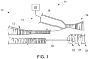
- the gas turbine engine 10 includes a compressor section 12 and a plurality of combustor assemblies arranged in a can annular array, one of which is indicated at 14.
- the combustor assembly is configured to receive fuel from a fuel supply system 20 through at least one fuel nozzle and a compressed air from the compressor section 12.
- the fuel and compressed air are passed into a combustor chamber 18 defined by a combustor liner and ignited to form a high temperature, high pressure combustion product or air stream that is used to drive a turbine 24.
- the turbine 24 includes a plurality of stages 26-28 that are operationally connected to the compressor 12 through a compressor/turbine shaft 30 (also referred to as a rotor).
- air flows into the compressor 12 and is compressed into a high pressure gas.
- the high pressure gas is supplied to the combustor assembly 14 and mixed with fuel, for example natural gas, fuel oil, process gas and/or synthetic gas (syngas), in the combustor chamber 18.
- fuel for example natural gas, fuel oil, process gas and/or synthetic gas (syngas)
- the fuel/air or combustible mixture ignites to form a high pressure, high temperature combustion gas stream, which is channeled to the turbine 24 and converted from thermal energy to mechanical, rotational energy.
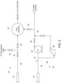
- the fuel provided is a liquid fuel, but it is to be appreciated that embodiments of the gas turbine engine 10 employ both liquid fuel and gas fuel, which may be employed during different operating conditions.
- the fuel supply system 20 includes a liquid fuel supply 32 that stores and distributes liquid fuel.
- the liquid fuel supply 32 is fluidly coupled to a liquid fuel manifold 34 with a liquid fuel piping arrangement 36.
- One or more valves 38 are included along the liquid fuel piping arrangement 36 to selectively transition between an open condition and a closed condition to control the flow rate of liquid fuel to the liquid fuel manifold 34.
- An atmospheric vent 39 in the form of a vent or drain is provided off of the liquid fuel piping arrangement 36.
- An internal pressure of the liquid fuel piping arrangement 36 is present due to the liquid fuel supply 32 being disposed at an elevated position relative to the one or more valves 38, as well as the atmospheric vent 39. Based on this internal pressure, it is possible for a leaked portion of the liquid fuel to pass through the one or more valves 38 when the valve(s) are in the closed condition.
- the purge system 40 is fluidly coupled to the combustor assembly 14 and is configured to purge various portions of the combustor assembly 14 with a liquid, such as water, via a water manifold. More specifically, the water is demineralized water in certain embodiments.
- the purge system 40 includes a liquid supply line 42 (e.g., water supply line) that is fluidly coupled to a liquid supply 44 (e.g., water supply) and a water manifold, as well as the liquid fuel manifold 34.
- a main portion 46 of the fluid supply line 42 is provided and routes the liquid to a liquid injection pump 48 (e.g., water injection pump) that is configured to pump the liquid to the water manifold along a liquid distribution line 50 and/or the liquid fuel manifold 34.
- a liquid valve 52 is provided between the liquid injection pump 48 and the liquid fuel manifold 34 to control the flow rate of liquid to the liquid fuel manifold 34.
- the liquid distribution line 50 includes a liquid valve 54 (e.g., water valve) that transitions between an open state and a closed state.
- the liquid injection pump 48 is configured to operate at a high pressure, relative to a liquid seal pump 56 (e.g., water seal pump) that is located along a liquid line branch 58 that branches off of the main portion 46 of the fluid supply line 42.
- the liquid seal pump 56 is employed when the liquid injection pump 48 is not in use and is used for sealing/pressurization purposes of various portions of the fluid lines.
- the liquid seal pump 56 pumps liquid to the liquid fuel manifold 34 to pressurize the components therein. Pressurization opposes the leaked portion of the liquid fuel that tends to pass through the one or more valves 38, thereby reducing the likelihood of ingress of the liquid fuel to the liquid fuel manifold 34 from upstream locations along the liquid fuel piping arrangement 36.
- the liquid pumped by the liquid seal pump 56 must exceed the internal pressure of the liquid fuel piping arrangement 36, which may vary depending upon the particular application and operating conditions.
- the liquid seal pump 56 is configured to pump the liquid at a pressure greater than about 13789 Pa (2 psig). In another embodiment, the pressure is greater than about 20684 Pa (3 psig), which is greater than the internal pressure of the liquid fuel piping arrangement 36.
- a method of purging the combustor assembly 14 of the gas turbine engine 10 is provided to avoid potential damage to the liquid fuel manifold 34 during a combustor assembly purging process, such as a purge credit mode.
- the one or more valve 38 is closed to inhibit flow of the liquid fuel to the liquid fuel manifold 34 during a purge operation of the combustor assembly 14. As described above, a slight leaked portion may persist through the valve(s).
- the liquid fuel manifold 34 is pressurized with a liquid from the liquid seal pump 56 that operates at a low power, yet providing a pumped liquid that is greater than the internal pressure of the liquid fuel piping arrangement 36. By employing a low power pump integrated in the fuel supply system 20, cost-effective and efficient protection of the liquid fuel manifold 34 is achieved.
Landscapes
- Engineering & Computer Science (AREA)
- Chemical & Material Sciences (AREA)
- Combustion & Propulsion (AREA)
- Mechanical Engineering (AREA)
- General Engineering & Computer Science (AREA)
- Feeding And Controlling Fuel (AREA)
- Turbine Rotor Nozzle Sealing (AREA)
Claims (14)
- Brennstoffspülsystem (40) für ein Gasturbinentriebwerk (10), umfassend einen Wasserverteiler, eine Wasserverteilungsleitung (50) und ein Wasserventil (52), das Brennstoffspülsystem (40) umfassend:einen Flüssigbrennstoffverteiler (34), der angepasst ist, um mit einer Flüssigbrennstoffversorgung (32) mit einer Flüssigbrennstoffrohrleitungsanordnung (36), umfassend ein oder mehrere Ventile (38), und mit einer Brennkammeranordnung (14) fluidisch verbunden zu werden, und konfiguriert ist, um einen Flüssigbrennstoff von der Brennstoffversorgung (32) aufzunehmen und den Flüssigbrennstoff an die Brennkammeranordnung (14) zu verteilen;ein Flüssigbrennstoffventil (38), das zwischen der Brennstoffversorgung und dem Brennstoffverteiler eingerichtet ist; undeine Flüssigkeitspumpe (56), die angepasst ist, um mit einer Flüssigkeitsversorgung (44) und mit dem Flüssigbrennstoffverteilerfluidisch verbunden zu werden, und konfiguriert ist, um eine Flüssigkeit von der Flüssigkeitsversorgung (44) aufzunehmen und die Flüssigkeit an den Flüssigbrennstoffverteiler für eine Druckbeaufschlagung des Flüssigbrennstoffverteilers während eines Spülvorgangs der Brennkammeranordnung zu verteilen, wobeidie Flüssigkeit Wasser umfasst, undeine Wassereinspritzpumpe (48) angepasst ist, um in Fluidverbindung mit der Flüssigkeitsversorgung und dem Wasserverteiler zu stehen, und konfiguriert ist, um Wasser aus der Flüssigkeitsversorgung (44) aufzunehmen, und das Wasser an den Wasserverteiler entlang der Wasserverteilungsleitung (50) während eines offenen Zustands des Wasserventils (52), das sich zwischen der Wassereinspritzpumpe und dem Wasserverteiler befindet, und an den Brennstoffverteiler zu verteilen; wobeidie Flüssigkeitspumpe eine Wasserdichtungspumpe ist, die konfiguriert ist, um eingesetzt zu werden, wenn die Wassereinspritzpumpe (48) nicht in Gebrauch ist, und konfiguriert ist, um Flüssigkeit zu dem Flüssigbrennstoffverteiler zu pumpen, um Komponenten des Flüssigbrennstoffverteilers druckzubeaufschlagen.
- Brennstoffspülsystem nach Anspruch 1, wobei die Flüssigkeit demineralisiertes Wasser umfasst.
- Brennstoffspülsystem nach einem der vorstehenden Ansprüche, wobei die Flüssigbrennstoffversorgung (32) mit dem Flüssigbrennstoffverteiler (34) über eine Flüssigbrennstoffrohrleitungsanordnung (36) fluidisch gekoppelt ist, und die Flüssigkeitspumpe (56) konfiguriert ist, um, Flüssigkeit mit einem Druck, der einen Innendruck der Flüssigbrennstoffrohrleitungsanordnung (36) übersteigt, zu pumpen.
- Brennstoffspülsystem nach Anspruch 1, wobei die Flüssigkeitspumpe angepasst ist, um mit dem Wasserventil (52) fluidisch verbunden zu werden, und konfiguriert ist, um Wasser während eines geschlossenen Zustands des Wasserventils zu pumpen.
- Brennstoffspülsystem nach einem der vorstehenden Ansprüche, wobei die Flüssigkeit mit einem Druck von mindestens 13789 Pa (2 psig) gepumpt wird.
- Brennstoffspülsystem nach einem der Ansprüche 1 bis 5, wobei die Flüssigkeit mit einem Druck von mindestens 20684 Pa (3 psig) gepumpt wird.
- Brennstoffspülsystem nach einem der vorstehenden Ansprüche, wobei die Flüssigkeit an den Brennstoffverteiler während eines geschlossenen Zustands des Flüssigbrennstoffventils verteilt wird, um einen austretenden Anteil des Flüssigbrennstoffs vom Eintreten in den Brennstoffverteiler zu mindern.
- Verfahren zum Spülen eines Gasturbinentriebwerks (10), umfassend:Schließen eines Flüssigbrennstoffventils (38), das sich zwischen einer Flüssigbrennstoffversorgung (32) und einem Flüssigbrennstoffverteiler (34) befindet;Schließen einer Wassereinspritzpumpe (48), die konfiguriert ist, um Wasser aus einer Flüssigkeitsversorgung (44) aufzunehmen und Wasser an einen Wasserverteiler und den Brennstoffverteiler zu verteilen; undDruckbeaufschlagen des Brennstoffverteilers mit Wasser aus einer Flüssigkeitsversorgung (44) mittels einer Flüssigkeitspumpe (56) während eines Spülvorgangs einer Brennkammeranordnung (14).
- Verfahren nach Anspruch 8, wobei die Flüssigbrennstoffversorgung (32) mit dem Flüssigbrennstoffverteiler (34) über eine Flüssigbrennstoffrohrleitungsanordnung (36) fluidisch gekoppelt ist, und die Flüssigkeit, die durch die Flüssigkeitspumpe (56) gepumpt wird, einen Innendruck der Flüssigbrennstoffrohrleitungsanordnung (36) übersteigt.
- Verfahren nach Anspruch 9, wobei das Wasser demineralisiertes Wasser umfasst.
- Verfahren nach Anspruch 8, 9 oder 10, ferner umfassend das Pumpen des Wassers bei einem Druck von mindestens 13789 Pa (2 psig).
- Verfahren nach Anspruch 8, 9 oder 10, ferner umfassend das Pumpen des Wassers bei einem Druck von mindestens 20684 Pa (3 psig).
- Verfahren nach einem der Ansprüche 9 bis 12, wobei die Wassereinspritzpumpe (48) in Fluidverbindung mit der Flüssigkeitsversorgung und einem Wasserverteiler steht, und ein Wasserverteiler Wasser aus der Flüssigkeitsversorgung aufnimmt, und das Wasser an den Wasserverteiler entlang einer Wasserverteilungsleitung (50) während eines offenen Zustands eines Wasserventils (52), das sich zwischen der Wassereinspritzpumpe und dem Wasserverteiler befindet, verteilt.
- Verfahren nach einem der Ansprüche 9 bis 13, wobei die Flüssigkeit, die durch die Flüssigkeitspumpe gepumpt wird, in einen ersten Strom und einen zweiten Strom getrennt wird, wobei der erste Strom zu dem Brennstoffverteiler geleitet wird und der zweite Strom zu dem Wasserverteiler geleitet wird.
Applications Claiming Priority (1)
| Application Number | Priority Date | Filing Date | Title |
|---|---|---|---|
| US14/558,279 US20160348594A1 (en) | 2014-12-02 | 2014-12-02 | Fuel purge system and method of purging |
Publications (2)
| Publication Number | Publication Date |
|---|---|
| EP3029299A1 EP3029299A1 (de) | 2016-06-08 |
| EP3029299B1 true EP3029299B1 (de) | 2024-10-02 |
Family
ID=54780100
Family Applications (1)
| Application Number | Title | Priority Date | Filing Date |
|---|---|---|---|
| EP15196738.7A Active EP3029299B1 (de) | 2014-12-02 | 2015-11-27 | Brennstoffentlüftungssystem und verfahren zur entlüftung |
Country Status (4)
| Country | Link |
|---|---|
| US (1) | US20160348594A1 (de) |
| EP (1) | EP3029299B1 (de) |
| JP (1) | JP2016118196A (de) |
| CN (1) | CN205746974U (de) |
Families Citing this family (3)
| Publication number | Priority date | Publication date | Assignee | Title |
|---|---|---|---|---|
| US10012148B2 (en) * | 2014-05-23 | 2018-07-03 | General Electric Company | Method of purging a combustor |
| US11598266B2 (en) * | 2020-12-21 | 2023-03-07 | General Electric Company | Liquid fuel steam purge system and method for gas turbine engine |
| IT202100021071A1 (it) * | 2021-08-04 | 2023-02-04 | Nuovo Pignone Tecnologie Srl | Improved Method for Estimating and Setting Exhaust Purge Time in a Combustion System and Combustion System Thereof. |
Family Cites Families (4)
| Publication number | Priority date | Publication date | Assignee | Title |
|---|---|---|---|---|
| DE59810159D1 (de) * | 1998-02-26 | 2003-12-18 | Alstom Switzerland Ltd | Verfahren zum sicheren Entfernen von Flüssigbrennstoff aus dem Brennstoffsystem einer Gasturbine sowie Vorrichtung zur Durchführung des Verfahrens |
| FR2938048B1 (fr) * | 2008-11-06 | 2015-03-06 | Ge Energy Products France Snc | Systeme et procede de lavage et purge a l'eau du circuit combustible liquide d'une turbine |
| EP2216529A1 (de) * | 2009-02-06 | 2010-08-11 | Siemens Aktiengesellschaft | Verfahren zum Spülen eines Abschnitts eines Brennstoffsystems einer Gasturbine |
| US9188061B2 (en) * | 2011-10-24 | 2015-11-17 | General Electric Company | System for turbine combustor fuel assembly |
-
2014
- 2014-12-02 US US14/558,279 patent/US20160348594A1/en not_active Abandoned
-
2015
- 2015-11-27 JP JP2015231200A patent/JP2016118196A/ja active Pending
- 2015-11-27 EP EP15196738.7A patent/EP3029299B1/de active Active
- 2015-12-02 CN CN201520983829.8U patent/CN205746974U/zh not_active Expired - Lifetime
Also Published As
| Publication number | Publication date |
|---|---|
| EP3029299A1 (de) | 2016-06-08 |
| JP2016118196A (ja) | 2016-06-30 |
| CN205746974U (zh) | 2016-11-30 |
| US20160348594A1 (en) | 2016-12-01 |
Similar Documents
| Publication | Publication Date | Title |
|---|---|---|
| US11788471B2 (en) | Systems and methods for preventing fuel leakage in a gas turbine engine | |
| US7712317B2 (en) | Flow control systems | |
| US7861536B2 (en) | Ejector controlled twin air source gas turbine pressurizing air system | |
| US9404424B2 (en) | Turbine conduit purge systems | |
| US20190112987A1 (en) | Electric cruise pump system | |
| US20220349343A1 (en) | Sweep flow structures for fuel systems | |
| US12320263B2 (en) | System and method for use of intercooler cooled fluid as bearing pressurization fluid source | |
| US9303562B2 (en) | Methods and systems for operating gas turbine engines | |
| US10533503B2 (en) | Method for starting a gas turbine | |
| EP3029299B1 (de) | Brennstoffentlüftungssystem und verfahren zur entlüftung | |
| CN101392687A (zh) | 用于增强涡轮机性能的冷却回路 | |
| EP2503101A2 (de) | System zur Regulierung einer Kühlflüssigkeit in einer Turbomaschine | |
| US11459959B2 (en) | Method for starting a gas turbine | |
| WO2023140891A3 (en) | Turbine engines having hydrogen fuel systems | |
| EP3095987B1 (de) | Brennstoffzufuhrsystem und verfahren für einen gasturbinenmotor | |
| US8221061B2 (en) | Gas turbine engine with valve for establishing communication between two enclosures | |
| US10563588B2 (en) | Fuel system with vacuum generator to purge fuel from fuel nozzles | |
| US20180142570A1 (en) | Purging liquid fuel nozzles and supply tubing with the assistance of a flow divider | |
| US11466859B2 (en) | Gap filler for a fuel system gallery | |
| US11118467B2 (en) | System and method for converting turbine cooling nozzle |
Legal Events
| Date | Code | Title | Description |
|---|---|---|---|
| PUAI | Public reference made under article 153(3) epc to a published international application that has entered the european phase |
Free format text: ORIGINAL CODE: 0009012 |
|
| AK | Designated contracting states |
Kind code of ref document: A1 Designated state(s): AL AT BE BG CH CY CZ DE DK EE ES FI FR GB GR HR HU IE IS IT LI LT LU LV MC MK MT NL NO PL PT RO RS SE SI SK SM TR |
|
| AX | Request for extension of the european patent |
Extension state: BA ME |
|
| STAA | Information on the status of an ep patent application or granted ep patent |
Free format text: STATUS: REQUEST FOR EXAMINATION WAS MADE |
|
| 17P | Request for examination filed |
Effective date: 20161208 |
|
| RBV | Designated contracting states (corrected) |
Designated state(s): AL AT BE BG CH CY CZ DE DK EE ES FI FR GB GR HR HU IE IS IT LI LT LU LV MC MK MT NL NO PL PT RO RS SE SI SK SM TR |
|
| STAA | Information on the status of an ep patent application or granted ep patent |
Free format text: STATUS: EXAMINATION IS IN PROGRESS |
|
| 17Q | First examination report despatched |
Effective date: 20181019 |
|
| RAP1 | Party data changed (applicant data changed or rights of an application transferred) |
Owner name: GENERAL ELECTRIC TECHNOLOGY GMBH |
|
| GRAP | Despatch of communication of intention to grant a patent |
Free format text: ORIGINAL CODE: EPIDOSNIGR1 |
|
| STAA | Information on the status of an ep patent application or granted ep patent |
Free format text: STATUS: GRANT OF PATENT IS INTENDED |
|
| INTG | Intention to grant announced |
Effective date: 20240325 |
|
| GRAS | Grant fee paid |
Free format text: ORIGINAL CODE: EPIDOSNIGR3 |
|
| GRAA | (expected) grant |
Free format text: ORIGINAL CODE: 0009210 |
|
| STAA | Information on the status of an ep patent application or granted ep patent |
Free format text: STATUS: THE PATENT HAS BEEN GRANTED |
|
| AK | Designated contracting states |
Kind code of ref document: B1 Designated state(s): AL AT BE BG CH CY CZ DE DK EE ES FI FR GB GR HR HU IE IS IT LI LT LU LV MC MK MT NL NO PL PT RO RS SE SI SK SM TR |
|
| REG | Reference to a national code |
Ref country code: GB Ref legal event code: FG4D |
|
| REG | Reference to a national code |
Ref country code: CH Ref legal event code: EP |
|
| REG | Reference to a national code |
Ref country code: IE Ref legal event code: FG4D |
|
| REG | Reference to a national code |
Ref country code: DE Ref legal event code: R096 Ref document number: 602015090027 Country of ref document: DE |
|
| REG | Reference to a national code |
Ref country code: LT Ref legal event code: MG9D |
|
| REG | Reference to a national code |
Ref country code: NL Ref legal event code: MP Effective date: 20241002 |
|
| REG | Reference to a national code |
Ref country code: AT Ref legal event code: MK05 Ref document number: 1728672 Country of ref document: AT Kind code of ref document: T Effective date: 20241002 |
|
| PG25 | Lapsed in a contracting state [announced via postgrant information from national office to epo] |
Ref country code: NL Free format text: LAPSE BECAUSE OF FAILURE TO SUBMIT A TRANSLATION OF THE DESCRIPTION OR TO PAY THE FEE WITHIN THE PRESCRIBED TIME-LIMIT Effective date: 20241002 |
|
| PG25 | Lapsed in a contracting state [announced via postgrant information from national office to epo] |
Ref country code: NL Free format text: LAPSE BECAUSE OF FAILURE TO SUBMIT A TRANSLATION OF THE DESCRIPTION OR TO PAY THE FEE WITHIN THE PRESCRIBED TIME-LIMIT Effective date: 20241002 |
|
| PG25 | Lapsed in a contracting state [announced via postgrant information from national office to epo] |
Ref country code: HR Free format text: LAPSE BECAUSE OF FAILURE TO SUBMIT A TRANSLATION OF THE DESCRIPTION OR TO PAY THE FEE WITHIN THE PRESCRIBED TIME-LIMIT Effective date: 20241002 Ref country code: PT Free format text: LAPSE BECAUSE OF FAILURE TO SUBMIT A TRANSLATION OF THE DESCRIPTION OR TO PAY THE FEE WITHIN THE PRESCRIBED TIME-LIMIT Effective date: 20250203 Ref country code: IS Free format text: LAPSE BECAUSE OF FAILURE TO SUBMIT A TRANSLATION OF THE DESCRIPTION OR TO PAY THE FEE WITHIN THE PRESCRIBED TIME-LIMIT Effective date: 20250202 |
|
| PG25 | Lapsed in a contracting state [announced via postgrant information from national office to epo] |
Ref country code: FI Free format text: LAPSE BECAUSE OF FAILURE TO SUBMIT A TRANSLATION OF THE DESCRIPTION OR TO PAY THE FEE WITHIN THE PRESCRIBED TIME-LIMIT Effective date: 20241002 |
|
| PG25 | Lapsed in a contracting state [announced via postgrant information from national office to epo] |
Ref country code: BG Free format text: LAPSE BECAUSE OF FAILURE TO SUBMIT A TRANSLATION OF THE DESCRIPTION OR TO PAY THE FEE WITHIN THE PRESCRIBED TIME-LIMIT Effective date: 20241002 |
|
| PG25 | Lapsed in a contracting state [announced via postgrant information from national office to epo] |
Ref country code: ES Free format text: LAPSE BECAUSE OF FAILURE TO SUBMIT A TRANSLATION OF THE DESCRIPTION OR TO PAY THE FEE WITHIN THE PRESCRIBED TIME-LIMIT Effective date: 20241002 |
|
| PG25 | Lapsed in a contracting state [announced via postgrant information from national office to epo] |
Ref country code: NO Free format text: LAPSE BECAUSE OF FAILURE TO SUBMIT A TRANSLATION OF THE DESCRIPTION OR TO PAY THE FEE WITHIN THE PRESCRIBED TIME-LIMIT Effective date: 20250102 |
|
| PG25 | Lapsed in a contracting state [announced via postgrant information from national office to epo] |
Ref country code: GR Free format text: LAPSE BECAUSE OF FAILURE TO SUBMIT A TRANSLATION OF THE DESCRIPTION OR TO PAY THE FEE WITHIN THE PRESCRIBED TIME-LIMIT Effective date: 20250103 Ref country code: LV Free format text: LAPSE BECAUSE OF FAILURE TO SUBMIT A TRANSLATION OF THE DESCRIPTION OR TO PAY THE FEE WITHIN THE PRESCRIBED TIME-LIMIT Effective date: 20241002 Ref country code: AT Free format text: LAPSE BECAUSE OF FAILURE TO SUBMIT A TRANSLATION OF THE DESCRIPTION OR TO PAY THE FEE WITHIN THE PRESCRIBED TIME-LIMIT Effective date: 20241002 |
|
| PG25 | Lapsed in a contracting state [announced via postgrant information from national office to epo] |
Ref country code: PL Free format text: LAPSE BECAUSE OF FAILURE TO SUBMIT A TRANSLATION OF THE DESCRIPTION OR TO PAY THE FEE WITHIN THE PRESCRIBED TIME-LIMIT Effective date: 20241002 Ref country code: CZ Free format text: LAPSE BECAUSE OF FAILURE TO SUBMIT A TRANSLATION OF THE DESCRIPTION OR TO PAY THE FEE WITHIN THE PRESCRIBED TIME-LIMIT Effective date: 20241002 |
|
| PG25 | Lapsed in a contracting state [announced via postgrant information from national office to epo] |
Ref country code: RS Free format text: LAPSE BECAUSE OF FAILURE TO SUBMIT A TRANSLATION OF THE DESCRIPTION OR TO PAY THE FEE WITHIN THE PRESCRIBED TIME-LIMIT Effective date: 20250102 |
|
| REG | Reference to a national code |
Ref country code: CH Ref legal event code: PL |
|
| PG25 | Lapsed in a contracting state [announced via postgrant information from national office to epo] |
Ref country code: SM Free format text: LAPSE BECAUSE OF FAILURE TO SUBMIT A TRANSLATION OF THE DESCRIPTION OR TO PAY THE FEE WITHIN THE PRESCRIBED TIME-LIMIT Effective date: 20241002 |
|
| REG | Reference to a national code |
Ref country code: DE Ref legal event code: R097 Ref document number: 602015090027 Country of ref document: DE |
|
| PG25 | Lapsed in a contracting state [announced via postgrant information from national office to epo] |
Ref country code: MC Free format text: LAPSE BECAUSE OF FAILURE TO SUBMIT A TRANSLATION OF THE DESCRIPTION OR TO PAY THE FEE WITHIN THE PRESCRIBED TIME-LIMIT Effective date: 20241002 |
|
| PG25 | Lapsed in a contracting state [announced via postgrant information from national office to epo] |
Ref country code: DK Free format text: LAPSE BECAUSE OF FAILURE TO SUBMIT A TRANSLATION OF THE DESCRIPTION OR TO PAY THE FEE WITHIN THE PRESCRIBED TIME-LIMIT Effective date: 20241002 |
|
| PG25 | Lapsed in a contracting state [announced via postgrant information from national office to epo] |
Ref country code: LU Free format text: LAPSE BECAUSE OF NON-PAYMENT OF DUE FEES Effective date: 20241127 |
|
| REG | Reference to a national code |
Ref country code: CH Ref legal event code: PL |
|
| PG25 | Lapsed in a contracting state [announced via postgrant information from national office to epo] |
Ref country code: EE Free format text: LAPSE BECAUSE OF FAILURE TO SUBMIT A TRANSLATION OF THE DESCRIPTION OR TO PAY THE FEE WITHIN THE PRESCRIBED TIME-LIMIT Effective date: 20241002 |
|
| PG25 | Lapsed in a contracting state [announced via postgrant information from national office to epo] |
Ref country code: CH Free format text: LAPSE BECAUSE OF NON-PAYMENT OF DUE FEES Effective date: 20241130 |
|
| PG25 | Lapsed in a contracting state [announced via postgrant information from national office to epo] |
Ref country code: RO Free format text: LAPSE BECAUSE OF FAILURE TO SUBMIT A TRANSLATION OF THE DESCRIPTION OR TO PAY THE FEE WITHIN THE PRESCRIBED TIME-LIMIT Effective date: 20241002 |
|
| PG25 | Lapsed in a contracting state [announced via postgrant information from national office to epo] |
Ref country code: SK Free format text: LAPSE BECAUSE OF FAILURE TO SUBMIT A TRANSLATION OF THE DESCRIPTION OR TO PAY THE FEE WITHIN THE PRESCRIBED TIME-LIMIT Effective date: 20241002 |
|
| PG25 | Lapsed in a contracting state [announced via postgrant information from national office to epo] |
Ref country code: IT Free format text: LAPSE BECAUSE OF FAILURE TO SUBMIT A TRANSLATION OF THE DESCRIPTION OR TO PAY THE FEE WITHIN THE PRESCRIBED TIME-LIMIT Effective date: 20241002 |
|
| PLBE | No opposition filed within time limit |
Free format text: ORIGINAL CODE: 0009261 |
|
| STAA | Information on the status of an ep patent application or granted ep patent |
Free format text: STATUS: NO OPPOSITION FILED WITHIN TIME LIMIT |
|
| REG | Reference to a national code |
Ref country code: BE Ref legal event code: MM Effective date: 20241130 |
|
| PG25 | Lapsed in a contracting state [announced via postgrant information from national office to epo] |
Ref country code: SE Free format text: LAPSE BECAUSE OF FAILURE TO SUBMIT A TRANSLATION OF THE DESCRIPTION OR TO PAY THE FEE WITHIN THE PRESCRIBED TIME-LIMIT Effective date: 20241002 |
|
| 26N | No opposition filed |
Effective date: 20250703 |
|
| GBPC | Gb: european patent ceased through non-payment of renewal fee |
Effective date: 20250102 |
|
| PG25 | Lapsed in a contracting state [announced via postgrant information from national office to epo] |
Ref country code: BE Free format text: LAPSE BECAUSE OF NON-PAYMENT OF DUE FEES Effective date: 20241130 Ref country code: GB Free format text: LAPSE BECAUSE OF NON-PAYMENT OF DUE FEES Effective date: 20250102 |
|
| PG25 | Lapsed in a contracting state [announced via postgrant information from national office to epo] |
Ref country code: FR Free format text: LAPSE BECAUSE OF NON-PAYMENT OF DUE FEES Effective date: 20241202 |
|
| PG25 | Lapsed in a contracting state [announced via postgrant information from national office to epo] |
Ref country code: IE Free format text: LAPSE BECAUSE OF NON-PAYMENT OF DUE FEES Effective date: 20241127 |
|
| PGFP | Annual fee paid to national office [announced via postgrant information from national office to epo] |
Ref country code: DE Payment date: 20251022 Year of fee payment: 11 |