EP3029298A1 - Turbomachine air inlets with liquid separation - Google Patents
Turbomachine air inlets with liquid separation Download PDFInfo
- Publication number
- EP3029298A1 EP3029298A1 EP15197223.9A EP15197223A EP3029298A1 EP 3029298 A1 EP3029298 A1 EP 3029298A1 EP 15197223 A EP15197223 A EP 15197223A EP 3029298 A1 EP3029298 A1 EP 3029298A1
- Authority
- EP
- European Patent Office
- Prior art keywords
- scoop
- air
- base
- inlet
- air outlet
- Prior art date
- Legal status (The legal status is an assumption and is not a legal conclusion. Google has not performed a legal analysis and makes no representation as to the accuracy of the status listed.)
- Granted
Links
Images


Classifications
-
- F—MECHANICAL ENGINEERING; LIGHTING; HEATING; WEAPONS; BLASTING
- F02—COMBUSTION ENGINES; HOT-GAS OR COMBUSTION-PRODUCT ENGINE PLANTS
- F02C—GAS-TURBINE PLANTS; AIR INTAKES FOR JET-PROPULSION PLANTS; CONTROLLING FUEL SUPPLY IN AIR-BREATHING JET-PROPULSION PLANTS
- F02C9/00—Controlling gas-turbine plants; Controlling fuel supply in air- breathing jet-propulsion plants
- F02C9/16—Control of working fluid flow
- F02C9/18—Control of working fluid flow by bleeding, bypassing or acting on variable working fluid interconnections between turbines or compressors or their stages
-
- F—MECHANICAL ENGINEERING; LIGHTING; HEATING; WEAPONS; BLASTING
- F02—COMBUSTION ENGINES; HOT-GAS OR COMBUSTION-PRODUCT ENGINE PLANTS
- F02C—GAS-TURBINE PLANTS; AIR INTAKES FOR JET-PROPULSION PLANTS; CONTROLLING FUEL SUPPLY IN AIR-BREATHING JET-PROPULSION PLANTS
- F02C7/00—Features, components parts, details or accessories, not provided for in, or of interest apart form groups F02C1/00 - F02C6/00; Air intakes for jet-propulsion plants
- F02C7/04—Air intakes for gas-turbine plants or jet-propulsion plants
- F02C7/05—Air intakes for gas-turbine plants or jet-propulsion plants having provisions for obviating the penetration of damaging objects or particles
-
- F—MECHANICAL ENGINEERING; LIGHTING; HEATING; WEAPONS; BLASTING
- F02—COMBUSTION ENGINES; HOT-GAS OR COMBUSTION-PRODUCT ENGINE PLANTS
- F02C—GAS-TURBINE PLANTS; AIR INTAKES FOR JET-PROPULSION PLANTS; CONTROLLING FUEL SUPPLY IN AIR-BREATHING JET-PROPULSION PLANTS
- F02C3/00—Gas-turbine plants characterised by the use of combustion products as the working fluid
- F02C3/04—Gas-turbine plants characterised by the use of combustion products as the working fluid having a turbine driving a compressor
-
- F—MECHANICAL ENGINEERING; LIGHTING; HEATING; WEAPONS; BLASTING
- F02—COMBUSTION ENGINES; HOT-GAS OR COMBUSTION-PRODUCT ENGINE PLANTS
- F02C—GAS-TURBINE PLANTS; AIR INTAKES FOR JET-PROPULSION PLANTS; CONTROLLING FUEL SUPPLY IN AIR-BREATHING JET-PROPULSION PLANTS
- F02C7/00—Features, components parts, details or accessories, not provided for in, or of interest apart form groups F02C1/00 - F02C6/00; Air intakes for jet-propulsion plants
- F02C7/06—Arrangements of bearings; Lubricating
-
- F—MECHANICAL ENGINEERING; LIGHTING; HEATING; WEAPONS; BLASTING
- F02—COMBUSTION ENGINES; HOT-GAS OR COMBUSTION-PRODUCT ENGINE PLANTS
- F02C—GAS-TURBINE PLANTS; AIR INTAKES FOR JET-PROPULSION PLANTS; CONTROLLING FUEL SUPPLY IN AIR-BREATHING JET-PROPULSION PLANTS
- F02C7/00—Features, components parts, details or accessories, not provided for in, or of interest apart form groups F02C1/00 - F02C6/00; Air intakes for jet-propulsion plants
- F02C7/12—Cooling of plants
- F02C7/16—Cooling of plants characterised by cooling medium
- F02C7/18—Cooling of plants characterised by cooling medium the medium being gaseous, e.g. air
-
- B—PERFORMING OPERATIONS; TRANSPORTING
- B01—PHYSICAL OR CHEMICAL PROCESSES OR APPARATUS IN GENERAL
- B01D—SEPARATION
- B01D45/00—Separating dispersed particles from gases or vapours by gravity, inertia, or centrifugal forces
- B01D45/04—Separating dispersed particles from gases or vapours by gravity, inertia, or centrifugal forces by utilising inertia
-
- B—PERFORMING OPERATIONS; TRANSPORTING
- B01—PHYSICAL OR CHEMICAL PROCESSES OR APPARATUS IN GENERAL
- B01D—SEPARATION
- B01D45/00—Separating dispersed particles from gases or vapours by gravity, inertia, or centrifugal forces
- B01D45/12—Separating dispersed particles from gases or vapours by gravity, inertia, or centrifugal forces by centrifugal forces
- B01D45/16—Separating dispersed particles from gases or vapours by gravity, inertia, or centrifugal forces by centrifugal forces generated by the winding course of the gas stream, the centrifugal forces being generated solely or partly by mechanical means, e.g. fixed swirl vanes
-
- F—MECHANICAL ENGINEERING; LIGHTING; HEATING; WEAPONS; BLASTING
- F05—INDEXING SCHEMES RELATING TO ENGINES OR PUMPS IN VARIOUS SUBCLASSES OF CLASSES F01-F04
- F05D—INDEXING SCHEME FOR ASPECTS RELATING TO NON-POSITIVE-DISPLACEMENT MACHINES OR ENGINES, GAS-TURBINES OR JET-PROPULSION PLANTS
- F05D2250/00—Geometry
- F05D2250/30—Arrangement of components
- F05D2250/32—Arrangement of components according to their shape
- F05D2250/323—Arrangement of components according to their shape convergent
-
- F—MECHANICAL ENGINEERING; LIGHTING; HEATING; WEAPONS; BLASTING
- F05—INDEXING SCHEMES RELATING TO ENGINES OR PUMPS IN VARIOUS SUBCLASSES OF CLASSES F01-F04
- F05D—INDEXING SCHEME FOR ASPECTS RELATING TO NON-POSITIVE-DISPLACEMENT MACHINES OR ENGINES, GAS-TURBINES OR JET-PROPULSION PLANTS
- F05D2250/00—Geometry
- F05D2250/50—Inlet or outlet
- F05D2250/51—Inlet
-
- F—MECHANICAL ENGINEERING; LIGHTING; HEATING; WEAPONS; BLASTING
- F05—INDEXING SCHEMES RELATING TO ENGINES OR PUMPS IN VARIOUS SUBCLASSES OF CLASSES F01-F04
- F05D—INDEXING SCHEME FOR ASPECTS RELATING TO NON-POSITIVE-DISPLACEMENT MACHINES OR ENGINES, GAS-TURBINES OR JET-PROPULSION PLANTS
- F05D2260/00—Function
- F05D2260/60—Fluid transfer
- F05D2260/609—Deoiling or demisting
-
- F—MECHANICAL ENGINEERING; LIGHTING; HEATING; WEAPONS; BLASTING
- F05—INDEXING SCHEMES RELATING TO ENGINES OR PUMPS IN VARIOUS SUBCLASSES OF CLASSES F01-F04
- F05D—INDEXING SCHEME FOR ASPECTS RELATING TO NON-POSITIVE-DISPLACEMENT MACHINES OR ENGINES, GAS-TURBINES OR JET-PROPULSION PLANTS
- F05D2260/00—Function
- F05D2260/98—Lubrication
-
- Y—GENERAL TAGGING OF NEW TECHNOLOGICAL DEVELOPMENTS; GENERAL TAGGING OF CROSS-SECTIONAL TECHNOLOGIES SPANNING OVER SEVERAL SECTIONS OF THE IPC; TECHNICAL SUBJECTS COVERED BY FORMER USPC CROSS-REFERENCE ART COLLECTIONS [XRACs] AND DIGESTS
- Y02—TECHNOLOGIES OR APPLICATIONS FOR MITIGATION OR ADAPTATION AGAINST CLIMATE CHANGE
- Y02T—CLIMATE CHANGE MITIGATION TECHNOLOGIES RELATED TO TRANSPORTATION
- Y02T50/00—Aeronautics or air transport
- Y02T50/60—Efficient propulsion technologies, e.g. for aircraft
Definitions
- the present disclosure relates to turbomachinery, more specifically to air inlets disposed on turbomachinery housing.
- core nacelles of turbomachines can include air scoops disposed thereon for guiding air from the bypass flow into the core for cooling through cooling holes defined in the core nacelle.
- turbomachines can be subject to oil leaks outside of the core nacelle which can streak and/or aerosolize into the air scoops.
- An air scoop includes a base which is attachable to a nacelle of a turbomachine, an air outlet defined in the base, and a scoop body disposed on the base and defining a scoop inlet.
- the scoop inlet is in fluid communication with the air outlet to supply scoop air to the air outlet.
- the air scoop also includes a separator lip extending from the base to the scoop inlet which spaces the scoop inlet apart from the base to raise the scoop body above liquids streaking along the base.
- the base can include one or more attachment holes.
- the scoop body can include a reducing cross-sectional flow area in a direction downstream from the scoop inlet.
- the scoop body can include a flat outer surface.
- the scoop body can include a round outer surface.
- the scoop body can include a flat inner surface, wherein the air outlet is defined in the flat inner surface.
- the scoop body can include a rounded inner surface, wherein the air outlet is defined in the rounded inner surface.
- the scoop body can include a scoop outlet aft of the scoop inlet and the air outlet.
- the scoop inlet can be semi-circular, circular, elliptical, or any other suitable shape.
- the separator lip can include a curved surface extending forward from the base.
- the separator lip can include an edged surface with two sides that meet at an apex under the scoop body.
- the two sides can be flat.
- the two sides can be curved.
- an air scoop can include a base which is attachable to a nacelle of a turbomachine, an air outlet defined in the base, and a scoop body disposed on the base and defining a scoop inlet, wherein the scoop inlet is in fluid communication with the air outlet to supply scoop air to the air outlet, wherein the scoop body includes a scoop outlet aft of the scoop inlet and the air outlet.
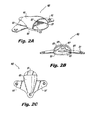
- FIG. 2A-2D an illustrative view of an exemplary embodiment of an air scoop in accordance with the disclosure is shown in Figs. 2A-2D and is designated generally by reference character 100.
- Other exemplary embodiments and/or aspects of this disclosure are shown in Figs. 1 and 3A-4D .
- the systems and methods described herein can be used to separate liquids (e.g., oil) from bypass airflow thereby reducing or preventing liquids from traveling into the core of a turbomachine through cooling holes.
- liquids e.g., oil
- Fig. 1 schematically illustrates a gas turbine engine 20.
- the gas turbine engine 20 is disclosed herein as a two-spool turbofan that generally incorporates a fan section 22, a compressor section 24, a combustor section 26 and a turbine section 28.
- Alternative engines might include an augmentor section (not shown) among other systems or features.
- the fan section 22 drives air along a bypass flow path B in a bypass duct defined within a nacelle 15, while the compressor section 24 drives air along a core flow path C for compression and communication into the combustor section 26 then expansion through the turbine section 28.
- the exemplary engine 20 generally includes a low speed spool 30 and a high speed spool 32 mounted for rotation about an engine central longitudinal axis A relative to an engine static structure 36 via several bearing systems 38. It should be understood that various bearing systems 38 at various locations may alternatively or additionally be provided and the location of bearing systems 38 may be varied as appropriate to the application.
- the low speed spool 30 generally includes an inner shaft 40 that interconnects a fan 42, a first (or low) pressure compressor 44 and a first (or low) pressure turbine 46.
- the inner shaft 40 is connected to the fan 42 through a speed change mechanism, which in exemplary gas turbine engine 20 is illustrated as a geared architecture 48 to drive the fan 42 at a lower speed than the low speed spool 30.
- the high speed spool 32 includes an outer shaft 50 that interconnects a second (or high) pressure compressor 52 and a second (or high) pressure turbine 54.
- a combustor 56 is arranged in exemplary gas turbine 20 between the high pressure compressor 52 and the high pressure turbine 54.
- a mid-turbine frame 57 of the engine static structure 36 is arranged generally between the high pressure turbine 54 and the low pressure turbine 46.
- the mid-turbine frame 57 further supports bearing systems 38 in the turbine section 28.
- the inner shaft 40 and the outer shaft 50 are concentric and rotate via bearing systems 38 about the engine central longitudinal axis A which is collinear with their longitudinal axes.
- the core airflow is compressed by the low pressure compressor 44 then the high pressure compressor 52, mixed and burned with fuel in the combustor 56, then expanded over the high pressure turbine 54 and low pressure turbine 46.
- the mid-turbine frame 57 includes airfoils 59 which are in the core airflow path C.
- the turbines 46, 54 rotationally drive the respective low speed spool 30 and high speed spool 32 in response to the expansion.
- gear system 48 may be located aft of combustor section 26 or even aft of turbine section 28, and fan section 22 may be positioned forward or aft of the location of gear system 48.
- the engine 20 in one example is a high-bypass geared aircraft engine.
- the engine 20 bypass ratio is greater than about six (6), with an example embodiment being greater than about ten (10)
- the geared architecture 48 is an epicyclic gear train, such as a planetary gear system or other gear system, with a gear reduction ratio of greater than about 2.3
- the low pressure turbine 46 has a pressure ratio that is greater than about five.
- the engine 20 bypass ratio is greater than about ten (10:1)
- the fan diameter is significantly larger than that of the low pressure compressor 44
- the low pressure turbine 46 has a pressure ratio that is greater than about five 5:1.
- Low pressure turbine 46 pressure ratio is pressure measured prior to inlet of low pressure turbine 46 as related to the pressure at the outlet of the low pressure turbine 46 prior to an exhaust nozzle.
- the geared architecture 48 may be an epicycle gear train, such as a planetary gear system or other gear system, with a gear reduction ratio of greater than about 2.3:1. It should be understood, however, that the above parameters are only exemplary of one embodiment of a geared architecture engine and that the present disclosure is applicable to other gas turbine engines including direct drive turbofans.
- the fan section 22 of the engine 20 is designed for a particular flight condition -- typically cruise at about 0.8 Mach and about 35,000 feet.
- the flight condition of 0.8 Mach and 35,000 ft (10,668 meters), with the engine at its best fuel consumption - also known as "bucket cruise Thrust Specific Fuel Consumption ('TSFC')" - is the industry standard parameter of lbm of fuel being burned divided by lbf of thrust the engine produces at that minimum point.
- “Low fan pressure ratio” is the pressure ratio across the fan blade alone, without a Fan Exit Guide Vane (“FEGV”) system.
- the low fan pressure ratio as disclosed herein according to one non-limiting embodiment is less than about 1.45.
- Low corrected fan tip speed is the actual fan tip speed in ft/sec divided by an industry standard temperature correction of [(Tram °R) / (518.7 °R)]0.5.
- the "Low corrected fan tip speed” as disclosed herein according to one non-limiting embodiment is less than about 1150 ft / second (350.5 meters/second).
- air scoop 100 includes a base 101 which is attachable to the inner wall of nacelle (e.g., nacelle 15) of a turbomachine (e.g., gas turbine engine 20).
- the air scoop 100 includes an air outlet 107 defined in the base 101 and a scoop body 103 disposed on the base 101.
- the air outlet 107 can be defined at an abrupt angle (e.g., about 90 degrees) relative to the direction of airflow. Any other suitable angle is contemplated herein.
- the scoop body 101 defines a scoop inlet 108 which is in fluid communication with the air outlet 107 to supply scoop air to the air outlet 107.
- the air outlet 107 supplies cooling air to the external components of the engine 20.
- the scoop inlet 108 can be semi-circular, however, it is contemplated that the scoop inlet 108 can include any suitable shape.
- the air scoop 100 also includes separator lip 105 extending from the base 101 to the scoop inlet 108 which spaces the scoop inlet 108 apart from the base 101 to raise the scoop body 103 above liquids (e.g., oil) streaking along the base 101.
- the separator lip 105 can include a curved surface extending forward from the base 101.
- any suitable lip shape is contemplated herein.
- the scoop body 103 can include a scoop outlet 109 aft of the scoop inlet 108 and the air outlet 107 for separating liquid particles from the air flow as described below.
- the scoop outlet 109 can include any suitable cross-sectional shape and/or area. While the scoop 100 is described as including a separator lip 105, it is contemplated that air scoop 100 can only include a scoop outlet 109 without separator lip 105.
- the base 101 can include one or more attachment holes 111 for attaching the scoop 100 to the core nacelle 33 via any suitable attachment (e.g., bolts, rivets). Any other suitable attachment is contemplated herein (e.g., adhesives, welding, forming the nacelle 33 with a scoop thereon).
- suitable attachment e.g., bolts, rivets.
- Any other suitable attachment is contemplated herein (e.g., adhesives, welding, forming the nacelle 33 with a scoop thereon).
- the scoop body 103 can include a reducing cross-sectional flow area in a direction downstream from the scoop inlet 108. This can speed up the airflow near the air outlet 107 for helping separate liquid from the airflow, as will be described in more detail below. Any other suitable internal profile is contemplated herein (e.g., a non-reducing cross-sectional area).
- the scoop body 103 can include a tapered and/or rounded outer surface as shown.
- the scoop body 103 can also include a flat inner surface 113 wherein the air outlet 107 is defined in the flat inner surface 113.
- the scoop body 103 can also include a protrusion 115 extending away from the scoop inlet 108.
- air scoop 200 includes a base 201, scoop body 203, a scoop inlet 208, an air outlet 207, and a scoop outlet 209 similar as described above.
- the scoop inlet 208 is semi-circular and/or pill-shaped.
- the scoop body 203 includes a partially flat outer surface unlike the air scoop 100 of Figs. 2A-2D .
- the air scoop 200 also includes separator lip 205 extending from the base 201 to the scoop inlet 208 which spaces the scoop inlet 208 apart from the base 201 to raise the scoop body 203 above liquids (e.g., oil, for reasons explained below) streaking along the nacelle wall 15.
- the separator lip 205 can include an edged surface with two sides that meet at an apex under the scoop body 203. As shown, the two sides can be flat. In other embodiments, the two sides can be at least partially curved.
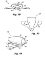
- air scoop 300 includes a base 301, scoop body 303, a scoop inlet 308, an air outlet 307, and a scoop outlet 309, and attachment holes 311 similar as described above.
- the scoop inlet 308 is circular.
- the scoop body 303 includes a rounded/tapered outer surface unlike the air scoop 200 of Figs. 3A-3C .
- the air scoop 300 also includes separator lip 305 extending from the base 301 to the scoop inlet 308 which functions in the same manner as separator lip 105.
- the separator lip 305 is similarly shaped as separator lip 205.
- the scoop body 303 of air scoop 300 includes a rounded inner surface 313 such that the air outlet 307 is defined in the rounded inner surface 313. Additionally, the scoop body 303 can include a ramp portion 315 configured to ramp airflow away from the air outlet 307 as shown in Fig. 4D .
- each air scoop 100, 200, 300 can be used to separate leaked oil and/or other liquids from bypass airflow to prevent oil from entering the core of the engine.
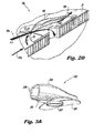
- airflow carrying oil droplets 121a can be separated from the oil droplets by the scoop body 103 since the air outlet 107 is disposed at a 90 degree angle relative to the direction of flow and the scoop outlet 109 is present. Since the oil droplets 121a have greater inertia than the air, the oil droplets 121a tend to continue through the scoop body 103 to the scoop outlet 109, whereas the airflow bends into the air outlet 107 to a lower pressure.
- separator lip 105 prevents streaking oil 121b from entering the scoop body 103 by diverting streaking oil 121b around the scoop body 103.
- Fig. 4D shows the embodiment of Fig. 4A separating oil from air flow.
- oil droplets 121a and streaking oil 121b are separated from the air flow by the scoop body 303 and the separator lip 305.
- ramp 315 increases the angle relative to the air outlet 307 so that the inertial forces of the oil droplets 121a in the air flow further prevent the oil droplets 121a from flowing into the air outlet 307.
Landscapes
- Engineering & Computer Science (AREA)
- Chemical & Material Sciences (AREA)
- Combustion & Propulsion (AREA)
- Mechanical Engineering (AREA)
- General Engineering & Computer Science (AREA)
- Physics & Mathematics (AREA)
- Fluid Mechanics (AREA)
- Structures Of Non-Positive Displacement Pumps (AREA)
Abstract
Description
- The present disclosure relates to turbomachinery, more specifically to air inlets disposed on turbomachinery housing.
- Traditionally, core nacelles of turbomachines can include air scoops disposed thereon for guiding air from the bypass flow into the core for cooling through cooling holes defined in the core nacelle. However, turbomachines can be subject to oil leaks outside of the core nacelle which can streak and/or aerosolize into the air scoops.
- Such conventional methods and systems have generally been considered satisfactory for their intended purpose. However, there is still a need in the art for improved air scoops. The present disclosure provides a solution for this need.
- An air scoop includes a base which is attachable to a nacelle of a turbomachine, an air outlet defined in the base, and a scoop body disposed on the base and defining a scoop inlet. The scoop inlet is in fluid communication with the air outlet to supply scoop air to the air outlet. The air scoop also includes a separator lip extending from the base to the scoop inlet which spaces the scoop inlet apart from the base to raise the scoop body above liquids streaking along the base.
- In addition to one or more of the features described above, or as an alternative to any of the foregoing embodiments, the base can include one or more attachment holes.
- In addition to one or more of the features described above, or as an alternative to any of the foregoing embodiments, the scoop body can include a reducing cross-sectional flow area in a direction downstream from the scoop inlet.
- In addition to one or more of the features described above, or as an alternative to any of the foregoing embodiments, the scoop body can include a flat outer surface.
- In addition to one or more of the features described above, or as an alternative to any of the foregoing embodiments, the scoop body can include a round outer surface.
- In addition to one or more of the features described above, or as an alternative to any of the foregoing embodiments, the scoop body can include a flat inner surface, wherein the air outlet is defined in the flat inner surface.
- In addition to one or more of the features described above, or as an alternative to any of the foregoing embodiments, the scoop body can include a rounded inner surface, wherein the air outlet is defined in the rounded inner surface.
- In addition to one or more of the features described above, or as an alternative to any of the foregoing embodiments, the scoop body can include a scoop outlet aft of the scoop inlet and the air outlet.
- In addition to one or more of the features described above, or as an alternative to any of the foregoing embodiments, the scoop inlet can be semi-circular, circular, elliptical, or any other suitable shape.
- In addition to one or more of the features described above, or as an alternative to any of the foregoing embodiments, the separator lip can include a curved surface extending forward from the base.
- In addition to one or more of the features described above, or as an alternative to any of the foregoing embodiments, the separator lip can include an edged surface with two sides that meet at an apex under the scoop body.
- In addition to one or more of the features described above, or as an alternative to any of the foregoing embodiments, the two sides can be flat.
- In addition to one or more of the features described above, or as an alternative to any of the foregoing embodiments, the two sides can be curved.
- In at least one aspect of this disclosure, an air scoop can include a base which is attachable to a nacelle of a turbomachine, an air outlet defined in the base, and a scoop body disposed on the base and defining a scoop inlet, wherein the scoop inlet is in fluid communication with the air outlet to supply scoop air to the air outlet, wherein the scoop body includes a scoop outlet aft of the scoop inlet and the air outlet.
- These and other features of the systems and methods of the subject disclosure will become more readily apparent to those skilled in the art from the following detailed description taken in conjunction with the drawings.
- So that those skilled in the art to which the subject disclosure appertains will readily understand how to make and use the devices and methods of the subject disclosure without undue experimentation, embodiments thereof will be described in detail herein below by way of example only and with reference to certain figures, wherein:
-
Fig. 1 is a partial cross-sectional view of a turbomachine in accordance with this disclosure, showing a partial internal and external view thereof; -
Fig. 2A is a perspective view of an embodiment of an air scoop in accordance with this disclosure, showing a scoop body extending from a base; -
Fig. 2B is a front elevation view of the air scoop ofFig. 2A , showing the internal structure of the air scoop; -
Fig. 2C is a top plan view of the air scoop ofFig. 2A , showing the outer profile of the scoop body; -
Fig. 2D is a cross-sectional side elevation view of the air scoop ofFig. 2A , schematically showing oil being separated from airflow by the air scoop; -
Fig. 3A is a perspective view of an embodiment of an air scoop in accordance with this disclosure, showing a scoop body extending from a base; -
Fig. 3B is a front elevation view of the air scoop ofFig. 3A , showing the internal structure of the air scoop; -
Fig. 3C is a top plan view of the air scoop ofFig. 3A , showing the outer profile of the scoop body; -
Fig. 4A is a perspective view of an embodiment of an air scoop in accordance with this disclosure, showing a scoop body extending from a base; -
Fig. 4B is a front elevation view of the air scoop ofFig. 4A , showing the internal structure of the air scoop; -
Fig. 4C is a top plan view of the air scoop ofFig. 4A , showing the outer profile of the scoop body; and -
Fig. 4D is a cross-sectional side elevation view of the air scoop ofFig. 4A , schematically showing oil being separated from airflow by the air scoop. - Reference will now be made to the drawings wherein like reference numerals identify similar structural features or aspects of the subject disclosure. For purposes of explanation and illustration, and not limitation, an illustrative view of an exemplary embodiment of an air scoop in accordance with the disclosure is shown in
Figs. 2A-2D and is designated generally byreference character 100. Other exemplary embodiments and/or aspects of this disclosure are shown inFigs. 1 and3A-4D . The systems and methods described herein can be used to separate liquids (e.g., oil) from bypass airflow thereby reducing or preventing liquids from traveling into the core of a turbomachine through cooling holes. -
Fig. 1 schematically illustrates agas turbine engine 20. Thegas turbine engine 20 is disclosed herein as a two-spool turbofan that generally incorporates afan section 22, acompressor section 24, a combustor section 26 and aturbine section 28. Alternative engines might include an augmentor section (not shown) among other systems or features. Thefan section 22 drives air along a bypass flow path B in a bypass duct defined within anacelle 15, while thecompressor section 24 drives air along a core flow path C for compression and communication into the combustor section 26 then expansion through theturbine section 28. Although depicted as a two-spool turbofan gas turbine engine in the disclosed non-limiting embodiment, it should be understood that the concepts described herein are not limited to use with two-spool turbofans as the teachings may be applied to other types of turbine engines including three-spool architectures. - The
exemplary engine 20 generally includes alow speed spool 30 and ahigh speed spool 32 mounted for rotation about an engine central longitudinal axis A relative to an enginestatic structure 36 viaseveral bearing systems 38. It should be understood that various bearingsystems 38 at various locations may alternatively or additionally be provided and the location of bearingsystems 38 may be varied as appropriate to the application. - The
low speed spool 30 generally includes aninner shaft 40 that interconnects a fan 42, a first (or low)pressure compressor 44 and a first (or low)pressure turbine 46. Theinner shaft 40 is connected to the fan 42 through a speed change mechanism, which in exemplarygas turbine engine 20 is illustrated as a gearedarchitecture 48 to drive the fan 42 at a lower speed than thelow speed spool 30. Thehigh speed spool 32 includes anouter shaft 50 that interconnects a second (or high)pressure compressor 52 and a second (or high) pressure turbine 54. A combustor 56 is arranged inexemplary gas turbine 20 between thehigh pressure compressor 52 and the high pressure turbine 54. A mid-turbine frame 57 of the enginestatic structure 36 is arranged generally between the high pressure turbine 54 and thelow pressure turbine 46. The mid-turbine frame 57 furthersupports bearing systems 38 in theturbine section 28. Theinner shaft 40 and theouter shaft 50 are concentric and rotate via bearingsystems 38 about the engine central longitudinal axis A which is collinear with their longitudinal axes. - The core airflow is compressed by the
low pressure compressor 44 then thehigh pressure compressor 52, mixed and burned with fuel in the combustor 56, then expanded over the high pressure turbine 54 andlow pressure turbine 46. The mid-turbine frame 57 includesairfoils 59 which are in the core airflow path C. Theturbines 46, 54 rotationally drive the respectivelow speed spool 30 andhigh speed spool 32 in response to the expansion. It will be appreciated that each of the positions of thefan section 22,compressor section 24, combustor section 26,turbine section 28, and fandrive gear system 48 may be varied. For example,gear system 48 may be located aft of combustor section 26 or even aft ofturbine section 28, andfan section 22 may be positioned forward or aft of the location ofgear system 48. - The
engine 20 in one example is a high-bypass geared aircraft engine. In a further example, theengine 20 bypass ratio is greater than about six (6), with an example embodiment being greater than about ten (10), the gearedarchitecture 48 is an epicyclic gear train, such as a planetary gear system or other gear system, with a gear reduction ratio of greater than about 2.3 and thelow pressure turbine 46 has a pressure ratio that is greater than about five. In one disclosed embodiment, theengine 20 bypass ratio is greater than about ten (10:1), the fan diameter is significantly larger than that of thelow pressure compressor 44, and thelow pressure turbine 46 has a pressure ratio that is greater than about five 5:1.Low pressure turbine 46 pressure ratio is pressure measured prior to inlet oflow pressure turbine 46 as related to the pressure at the outlet of thelow pressure turbine 46 prior to an exhaust nozzle. The gearedarchitecture 48 may be an epicycle gear train, such as a planetary gear system or other gear system, with a gear reduction ratio of greater than about 2.3:1. It should be understood, however, that the above parameters are only exemplary of one embodiment of a geared architecture engine and that the present disclosure is applicable to other gas turbine engines including direct drive turbofans. - A significant amount of thrust is provided by the bypass flow B due to the high bypass ratio. The
fan section 22 of theengine 20 is designed for a particular flight condition -- typically cruise at about 0.8 Mach and about 35,000 feet. The flight condition of 0.8 Mach and 35,000 ft (10,668 meters), with the engine at its best fuel consumption - also known as "bucket cruise Thrust Specific Fuel Consumption ('TSFC')" - is the industry standard parameter of lbm of fuel being burned divided by lbf of thrust the engine produces at that minimum point. "Low fan pressure ratio" is the pressure ratio across the fan blade alone, without a Fan Exit Guide Vane ("FEGV") system. The low fan pressure ratio as disclosed herein according to one non-limiting embodiment is less than about 1.45. "Low corrected fan tip speed" is the actual fan tip speed in ft/sec divided by an industry standard temperature correction of [(Tram °R) / (518.7 °R)]0.5. The "Low corrected fan tip speed" as disclosed herein according to one non-limiting embodiment is less than about 1150 ft / second (350.5 meters/second). - Referring to
Figs. 2A-2D ,air scoop 100 includes a base 101 which is attachable to the inner wall of nacelle (e.g., nacelle 15) of a turbomachine (e.g., gas turbine engine 20). Theair scoop 100 includes anair outlet 107 defined in thebase 101 and ascoop body 103 disposed on thebase 101. Theair outlet 107 can be defined at an abrupt angle (e.g., about 90 degrees) relative to the direction of airflow. Any other suitable angle is contemplated herein. - The
scoop body 101 defines a scoop inlet 108 which is in fluid communication with theair outlet 107 to supply scoop air to theair outlet 107. Theair outlet 107 supplies cooling air to the external components of theengine 20. The scoop inlet 108 can be semi-circular, however, it is contemplated that the scoop inlet 108 can include any suitable shape. - The
air scoop 100 also includesseparator lip 105 extending from the base 101 to the scoop inlet 108 which spaces the scoop inlet 108 apart from the base 101 to raise thescoop body 103 above liquids (e.g., oil) streaking along thebase 101. As shown inFigs. 2A-2D , theseparator lip 105 can include a curved surface extending forward from thebase 101. However, any suitable lip shape is contemplated herein. - In certain embodiments, the
scoop body 103 can include ascoop outlet 109 aft of the scoop inlet 108 and theair outlet 107 for separating liquid particles from the air flow as described below. Thescoop outlet 109 can include any suitable cross-sectional shape and/or area. While thescoop 100 is described as including aseparator lip 105, it is contemplated thatair scoop 100 can only include ascoop outlet 109 withoutseparator lip 105. - The base 101 can include one or more attachment holes 111 for attaching the
scoop 100 to thecore nacelle 33 via any suitable attachment (e.g., bolts, rivets). Any other suitable attachment is contemplated herein (e.g., adhesives, welding, forming thenacelle 33 with a scoop thereon). - As shown, the
scoop body 103 can include a reducing cross-sectional flow area in a direction downstream from the scoop inlet 108. This can speed up the airflow near theair outlet 107 for helping separate liquid from the airflow, as will be described in more detail below. Any other suitable internal profile is contemplated herein (e.g., a non-reducing cross-sectional area). - The
scoop body 103 can include a tapered and/or rounded outer surface as shown. Thescoop body 103 can also include a flatinner surface 113 wherein theair outlet 107 is defined in the flatinner surface 113. Thescoop body 103 can also include aprotrusion 115 extending away from the scoop inlet 108. - Referring to
Figs. 3A-3C ,air scoop 200 includes abase 201,scoop body 203, ascoop inlet 208, anair outlet 207, and ascoop outlet 209 similar as described above. Thescoop inlet 208 is semi-circular and/or pill-shaped. As shown, thescoop body 203 includes a partially flat outer surface unlike theair scoop 100 ofFigs. 2A-2D . - The
air scoop 200 also includesseparator lip 205 extending from the base 201 to thescoop inlet 208 which spaces thescoop inlet 208 apart from the base 201 to raise thescoop body 203 above liquids (e.g., oil, for reasons explained below) streaking along thenacelle wall 15. Theseparator lip 205 can include an edged surface with two sides that meet at an apex under thescoop body 203. As shown, the two sides can be flat. In other embodiments, the two sides can be at least partially curved. - Referring to
Figs. 4A-4D ,air scoop 300 includes abase 301,scoop body 303, ascoop inlet 308, anair outlet 307, and ascoop outlet 309, and attachment holes 311 similar as described above. Thescoop inlet 308 is circular. As shown, thescoop body 303 includes a rounded/tapered outer surface unlike theair scoop 200 ofFigs. 3A-3C . - The
air scoop 300 also includesseparator lip 305 extending from the base 301 to thescoop inlet 308 which functions in the same manner asseparator lip 105. Theseparator lip 305 is similarly shaped asseparator lip 205. Thescoop body 303 ofair scoop 300 includes a roundedinner surface 313 such that theair outlet 307 is defined in the roundedinner surface 313. Additionally, thescoop body 303 can include aramp portion 315 configured to ramp airflow away from theair outlet 307 as shown inFig. 4D . - As described herein, each
air scoop Fig. 2D , airflow carryingoil droplets 121a can be separated from the oil droplets by thescoop body 103 since theair outlet 107 is disposed at a 90 degree angle relative to the direction of flow and thescoop outlet 109 is present. Since theoil droplets 121a have greater inertia than the air, theoil droplets 121a tend to continue through thescoop body 103 to thescoop outlet 109, whereas the airflow bends into theair outlet 107 to a lower pressure. At the same time,separator lip 105 prevents streakingoil 121b from entering thescoop body 103 by divertingstreaking oil 121b around thescoop body 103. -
Fig. 4D shows the embodiment ofFig. 4A separating oil from air flow. For similar reasons,oil droplets 121a and streakingoil 121b are separated from the air flow by thescoop body 303 and theseparator lip 305. Additionally, ramp 315 increases the angle relative to theair outlet 307 so that the inertial forces of theoil droplets 121a in the air flow further prevent theoil droplets 121a from flowing into theair outlet 307. - The methods and systems of the present disclosure, as described above and shown in the drawings, provide for air scoops with superior properties including air flow and liquid separation. While the apparatus and methods of the subject disclosure have been shown and described with reference to embodiments, those skilled in the art will readily appreciate that changes and/or modifications may be made thereto without departing from the scope of the subject disclosure.
- The following clauses provide details of the disclosure which may or may not presently be claimed, but which may form basis for future amendments or a divisional application.
- 1. An air scoop, comprising:
- a base which is attachable to a nacelle of a turbomachine;
- an air outlet defined in the base;
- a scoop body disposed on the base and defining a scoop inlet, wherein the scoop inlet is in fluid communication with the air outlet to supply scoop air to the air outlet; and
- a separator lip extending from the base to the scoop inlet which spaces the scoop inlet apart from the base to raise the scoop body above liquids streaking along the base.
- 2. The air scoop of clause 1, wherein the base includes one or more attachment holes.
- 3. The air scoop of clause 1, wherein the scoop body includes a reducing cross-sectional flow area in a direction downstream from the scoop inlet.
- 4. The air scoop of clause 1, wherein the scoop body includes a flat outer surface.
- 5. The air scoop of clause 1, wherein the scoop body includes a round outer surface.
- 6. The air scoop of clause 1, wherein the scoop body includes a flat inner surface, wherein the air outlet is defined in the flat inner surface.
- 7. The air scoop of clause 1, wherein the scoop body includes a rounded inner surface, wherein the air outlet is defined in the rounded inner surface.
- 8. The air scoop of clause 1, wherein the scoop body includes a scoop outlet aft of the scoop inlet and the air outlet.
- 9. The air scoop of clause 1, wherein the scoop inlet is semi-circular.
- 10. The air scoop of clause 1, wherein the scoop inlet is circular.
- 11. The air scoop of clause 1, wherein the separator lip includes a curved surface extending forward from the base.
- 12. The air scoop of clause 1, wherein the separator lip includes an edged surface with two sides that meet at an apex under the scoop body.
- 13. The air scoop of clause 12, wherein the two sides are flat.
- 14. The air scoop of clause 12, wherein the two sides are curved.
- 15. An air scoop, comprising:
- a base which is attachable to a nacelle of a turbomachine;
- an air outlet defined in the base; and
Claims (15)
- An air scoop, comprising:a base (101; 201; 301) which is attachable to a nacelle of a turbomachine;an air outlet (107; 207; 307) defined in the base;a scoop body (103; 203; 303) disposed on the base and defining a scoop inlet (108; 208; 308), wherein the scoop inlet is in fluid communication with the air outlet to supply scoop air to the air outlet; anda separator lip (105; 205; 305) extending from the base to the scoop inlet which spaces the scoop inlet apart from the base to raise the scoop body above liquids streaking along the base.
- The air scoop of claim 1, wherein the base (101; 201; 301) includes one or more attachment holes.
- The air scoop of claim 1 or 2, wherein the scoop body (103; 203; 303) includes a reducing cross-sectional flow area in a direction downstream from the scoop inlet (108; 208; 308).
- The air scoop of claim 1, 2 or 3, wherein the scoop body (203) includes a flat outer surface.
- The air scoop of claim 1, 2 or 3, wherein the scoop body (103; 303) includes a round outer surface.
- The air scoop of any preceding claim, wherein the scoop body (103; 203) includes a flat inner surface, wherein the air outlet (107; 207) is defined in the flat inner surface.
- The air scoop of any of claims 1 to 5, wherein the scoop body (303) includes a rounded inner surface, wherein the air outlet (307) is defined in the rounded inner surface.
- The air scoop of any preceding claim, wherein the scoop body (103; 203; 303) includes a scoop outlet (109; 209; 309) aft of the scoop inlet (108; 208; 308) and the air outlet (107; 207; 307).
- The air scoop of claim 1, 2 or 3, wherein the scoop inlet (108) is semi-circular.
- The air scoop of claim 1, 2 or 3, wherein the scoop inlet (308) is circular.
- The air scoop of claim 1, 2 or 3, wherein the separator lip (105) includes a curved surface extending forward from the base (101).
- The air scoop of claim 1, 2 or 3, wherein the separator lip (205) includes an edged surface with two sides that meet at an apex under the scoop body.
- The air scoop of claim 12, wherein the two sides are flat.
- The air scoop of claim 12, wherein the two sides are curved.
- An air scoop, comprising:a base (101; 201; 301) which is attachable to a nacelle of a turbomachine;an air outlet (107; 207; 307) defined in the base; anda scoop body (103; 203; 303) disposed on the base and defining a scoop inlet (108; 208; 308), wherein the scoop inlet is in fluid communication with the air outlet to supply scoop air to the air outlet, wherein the scoop body includes a scoop outlet (109; 209; 309) aft of the scoop inlet and the air outlet.
Applications Claiming Priority (1)
| Application Number | Priority Date | Filing Date | Title |
|---|---|---|---|
| US201462086050P | 2014-12-01 | 2014-12-01 |
Publications (2)
| Publication Number | Publication Date |
|---|---|
| EP3029298A1 true EP3029298A1 (en) | 2016-06-08 |
| EP3029298B1 EP3029298B1 (en) | 2017-09-20 |
Family
ID=54783382
Family Applications (1)
| Application Number | Title | Priority Date | Filing Date |
|---|---|---|---|
| EP15197223.9A Active EP3029298B1 (en) | 2014-12-01 | 2015-12-01 | Turbomachine air inlets with liquid separation |
Country Status (2)
| Country | Link |
|---|---|
| US (1) | US20160153363A1 (en) |
| EP (1) | EP3029298B1 (en) |
Families Citing this family (7)
| Publication number | Priority date | Publication date | Assignee | Title |
|---|---|---|---|---|
| US9228747B2 (en) * | 2013-03-12 | 2016-01-05 | Pratt & Whitney Canada Corp. | Combustor for gas turbine engine |
| GB201705802D0 (en) * | 2017-04-11 | 2017-05-24 | Rolls Royce Plc | Inlet duct |
| US10557416B2 (en) | 2017-06-12 | 2020-02-11 | United Technologies Corporation | Flow modulating airfoil apparatus |
| US11415319B2 (en) * | 2017-12-19 | 2022-08-16 | Raytheon Technologies Corporation | Apparatus and method for mitigating particulate accumulation on a component of a gas turbine |
| US11300002B2 (en) | 2018-12-07 | 2022-04-12 | Pratt & Whitney Canada Corp. | Static take-off port |
| US20250108929A1 (en) * | 2023-10-02 | 2025-04-03 | The Boeing Company | Two Piece Nested Air Intake Scoop for Engine Cowl |
| EP4545417A1 (en) * | 2023-10-26 | 2025-04-30 | AIRBUS HELICOPTERS DEUTSCHLAND GmbH | An air directing arrangement for controlling airflow at an outlet |
Citations (6)
| Publication number | Priority date | Publication date | Assignee | Title |
|---|---|---|---|---|
| US4456458A (en) * | 1982-09-20 | 1984-06-26 | The De Havilland Aircraft Of Canada, Limited | Air intake system for engine |
| US20080099631A1 (en) * | 2006-10-26 | 2008-05-01 | Parikh Pradip G | Tandem air inlet apparatus and method for an airborne mobile platform |
| US20100150700A1 (en) * | 2008-12-16 | 2010-06-17 | Pratt & Whitney Canada Corp. | Bypass air scoop for gas turbine engine |
| US20100215481A1 (en) * | 2009-02-26 | 2010-08-26 | Rolls-Royce Deutschland Ltd & Co Kg | Running-gap control system of an aircraft gas turbine |
| US20100223905A1 (en) * | 2009-03-04 | 2010-09-09 | Rolls-Royce Deutschland Ltd & Co Kg | Scoop of a running-gap control system of an aircraft gas turbine |
| US20140037437A1 (en) * | 2012-07-31 | 2014-02-06 | Joshua V. Wood | Retrofitable auxiliary inlet scoop |
Family Cites Families (7)
| Publication number | Priority date | Publication date | Assignee | Title |
|---|---|---|---|---|
| US3329377A (en) * | 1965-10-11 | 1967-07-04 | United Aircraft Canada | Protection for aircraft engines against snow, ice and airborne particles |
| US4121606A (en) * | 1977-10-25 | 1978-10-24 | General Dynamics Corporation | Inflatable air inlet duct |
| US4972672A (en) * | 1989-09-28 | 1990-11-27 | Pratt & Whitney Canada, Inc. | Controlled bypass inlet duct |
| US5120004A (en) * | 1990-02-05 | 1992-06-09 | Rohr, Inc. | Split door thrust reverser for fan jet aircraft engines |
| US7861968B2 (en) * | 2006-10-26 | 2011-01-04 | The Boeing Company | Air inlet and method for a highspeed mobile platform |
| US9051057B2 (en) * | 2011-12-28 | 2015-06-09 | Embraer S.A. | Aircraft air inlet diverter assemblies with improved aerodynamic characteristics |
| US9054998B2 (en) * | 2013-02-06 | 2015-06-09 | Freescale Semiconductor, Inc. | System and method for maintaining packet order in an ordered data stream |
-
2015
- 2015-11-30 US US14/954,603 patent/US20160153363A1/en not_active Abandoned
- 2015-12-01 EP EP15197223.9A patent/EP3029298B1/en active Active
Patent Citations (6)
| Publication number | Priority date | Publication date | Assignee | Title |
|---|---|---|---|---|
| US4456458A (en) * | 1982-09-20 | 1984-06-26 | The De Havilland Aircraft Of Canada, Limited | Air intake system for engine |
| US20080099631A1 (en) * | 2006-10-26 | 2008-05-01 | Parikh Pradip G | Tandem air inlet apparatus and method for an airborne mobile platform |
| US20100150700A1 (en) * | 2008-12-16 | 2010-06-17 | Pratt & Whitney Canada Corp. | Bypass air scoop for gas turbine engine |
| US20100215481A1 (en) * | 2009-02-26 | 2010-08-26 | Rolls-Royce Deutschland Ltd & Co Kg | Running-gap control system of an aircraft gas turbine |
| US20100223905A1 (en) * | 2009-03-04 | 2010-09-09 | Rolls-Royce Deutschland Ltd & Co Kg | Scoop of a running-gap control system of an aircraft gas turbine |
| US20140037437A1 (en) * | 2012-07-31 | 2014-02-06 | Joshua V. Wood | Retrofitable auxiliary inlet scoop |
Also Published As
| Publication number | Publication date |
|---|---|
| EP3029298B1 (en) | 2017-09-20 |
| US20160153363A1 (en) | 2016-06-02 |
Similar Documents
| Publication | Publication Date | Title |
|---|---|---|
| EP3029298B1 (en) | Turbomachine air inlets with liquid separation | |
| EP3009599A1 (en) | Gas turbine engine component with film cooling hole feature | |
| EP2942488B1 (en) | Blade for a gas turbine engine, gas turbine engine and method of cooling a blade for a gas turbine engine | |
| EP3034791B1 (en) | Heat transfer pedestals with flow guide features | |
| EP3108110B1 (en) | Gas turbine engine airfoil | |
| EP3034794A1 (en) | Gas turbine engine component and corresponding wall | |
| EP2971656B1 (en) | Aerodynamic track fairing for a gas turbine engine fan nacelle | |
| EP3094823B1 (en) | Gas turbine engine component and corresponding gas turbine engine | |
| EP3246523A1 (en) | Cooled blade outer air seal | |
| EP2993304A1 (en) | Gas turbine engine component with film cooling hole | |
| EP3477056B1 (en) | Gas turbine engine airfoil array | |
| EP3296519A1 (en) | Flowpath component for a gas turbine engine including a chordal seal | |
| EP3266983A1 (en) | Cooling system for an airfoil of a gas powered turbine | |
| EP2993303B1 (en) | Gas turbine engine component with film cooling hole with pocket | |
| EP3150800A1 (en) | Airfoil baffle with wedge region | |
| EP2904252B2 (en) | Static guide vane with internal hollow channels | |
| EP3078813B1 (en) | Fan section comprising a blade platform seal with leading edge winglet and associated gas turbine engine | |
| EP3045666B1 (en) | Airfoil platform with cooling feed orifices | |
| EP3101236A1 (en) | Trailing edge platform seals | |
| US20150377048A1 (en) | Stator vane assembly and method therefore | |
| US11028779B2 (en) | Gas turbine engine bypass drainage systems | |
| EP2947272A1 (en) | Gas turbine engine stator vane baffle arrangement | |
| EP3192974A1 (en) | Gas turbine engine component and corresponding gas turbine engine | |
| EP3008290B1 (en) | Turbine vane with variable trailing edge inner radius | |
| EP3907373A1 (en) | Turbine blade cooling hole combination |
Legal Events
| Date | Code | Title | Description |
|---|---|---|---|
| PUAI | Public reference made under article 153(3) epc to a published international application that has entered the european phase |
Free format text: ORIGINAL CODE: 0009012 |
|
| AK | Designated contracting states |
Kind code of ref document: A1 Designated state(s): AL AT BE BG CH CY CZ DE DK EE ES FI FR GB GR HR HU IE IS IT LI LT LU LV MC MK MT NL NO PL PT RO RS SE SI SK SM TR |
|
| AX | Request for extension of the european patent |
Extension state: BA ME |
|
| RAP1 | Party data changed (applicant data changed or rights of an application transferred) |
Owner name: UNITED TECHNOLOGIES CORPORATION |
|
| STAA | Information on the status of an ep patent application or granted ep patent |
Free format text: STATUS: REQUEST FOR EXAMINATION WAS MADE |
|
| 17P | Request for examination filed |
Effective date: 20161208 |
|
| RBV | Designated contracting states (corrected) |
Designated state(s): AL AT BE BG CH CY CZ DE DK EE ES FI FR GB GR HR HU IE IS IT LI LT LU LV MC MK MT NL NO PL PT RO RS SE SI SK SM TR |
|
| GRAP | Despatch of communication of intention to grant a patent |
Free format text: ORIGINAL CODE: EPIDOSNIGR1 |
|
| STAA | Information on the status of an ep patent application or granted ep patent |
Free format text: STATUS: GRANT OF PATENT IS INTENDED |
|
| RIC1 | Information provided on ipc code assigned before grant |
Ipc: B01D 45/04 20060101ALI20170227BHEP Ipc: F02C 7/05 20060101AFI20170227BHEP Ipc: B01D 45/16 20060101ALI20170227BHEP Ipc: F02C 7/18 20060101ALI20170227BHEP |
|
| INTG | Intention to grant announced |
Effective date: 20170321 |
|
| GRAS | Grant fee paid |
Free format text: ORIGINAL CODE: EPIDOSNIGR3 |
|
| GRAA | (expected) grant |
Free format text: ORIGINAL CODE: 0009210 |
|
| STAA | Information on the status of an ep patent application or granted ep patent |
Free format text: STATUS: THE PATENT HAS BEEN GRANTED |
|
| AK | Designated contracting states |
Kind code of ref document: B1 Designated state(s): AL AT BE BG CH CY CZ DE DK EE ES FI FR GB GR HR HU IE IS IT LI LT LU LV MC MK MT NL NO PL PT RO RS SE SI SK SM TR |
|
| REG | Reference to a national code |
Ref country code: GB Ref legal event code: FG4D |
|
| REG | Reference to a national code |
Ref country code: CH Ref legal event code: EP |
|
| REG | Reference to a national code |
Ref country code: AT Ref legal event code: REF Ref document number: 930330 Country of ref document: AT Kind code of ref document: T Effective date: 20171015 |
|
| REG | Reference to a national code |
Ref country code: IE Ref legal event code: FG4D |
|
| REG | Reference to a national code |
Ref country code: DE Ref legal event code: R096 Ref document number: 602015004880 Country of ref document: DE |
|
| REG | Reference to a national code |
Ref country code: FR Ref legal event code: PLFP Year of fee payment: 3 |
|
| REG | Reference to a national code |
Ref country code: NL Ref legal event code: MP Effective date: 20170920 |
|
| PG25 | Lapsed in a contracting state [announced via postgrant information from national office to epo] |
Ref country code: FI Free format text: LAPSE BECAUSE OF FAILURE TO SUBMIT A TRANSLATION OF THE DESCRIPTION OR TO PAY THE FEE WITHIN THE PRESCRIBED TIME-LIMIT Effective date: 20170920 Ref country code: SE Free format text: LAPSE BECAUSE OF FAILURE TO SUBMIT A TRANSLATION OF THE DESCRIPTION OR TO PAY THE FEE WITHIN THE PRESCRIBED TIME-LIMIT Effective date: 20170920 Ref country code: HR Free format text: LAPSE BECAUSE OF FAILURE TO SUBMIT A TRANSLATION OF THE DESCRIPTION OR TO PAY THE FEE WITHIN THE PRESCRIBED TIME-LIMIT Effective date: 20170920 Ref country code: LT Free format text: LAPSE BECAUSE OF FAILURE TO SUBMIT A TRANSLATION OF THE DESCRIPTION OR TO PAY THE FEE WITHIN THE PRESCRIBED TIME-LIMIT Effective date: 20170920 Ref country code: NO Free format text: LAPSE BECAUSE OF FAILURE TO SUBMIT A TRANSLATION OF THE DESCRIPTION OR TO PAY THE FEE WITHIN THE PRESCRIBED TIME-LIMIT Effective date: 20171220 |
|
| REG | Reference to a national code |
Ref country code: LT Ref legal event code: MG4D |
|
| REG | Reference to a national code |
Ref country code: AT Ref legal event code: MK05 Ref document number: 930330 Country of ref document: AT Kind code of ref document: T Effective date: 20170920 |
|
| PG25 | Lapsed in a contracting state [announced via postgrant information from national office to epo] |
Ref country code: RS Free format text: LAPSE BECAUSE OF FAILURE TO SUBMIT A TRANSLATION OF THE DESCRIPTION OR TO PAY THE FEE WITHIN THE PRESCRIBED TIME-LIMIT Effective date: 20170920 Ref country code: GR Free format text: LAPSE BECAUSE OF FAILURE TO SUBMIT A TRANSLATION OF THE DESCRIPTION OR TO PAY THE FEE WITHIN THE PRESCRIBED TIME-LIMIT Effective date: 20171221 Ref country code: LV Free format text: LAPSE BECAUSE OF FAILURE TO SUBMIT A TRANSLATION OF THE DESCRIPTION OR TO PAY THE FEE WITHIN THE PRESCRIBED TIME-LIMIT Effective date: 20170920 Ref country code: BG Free format text: LAPSE BECAUSE OF FAILURE TO SUBMIT A TRANSLATION OF THE DESCRIPTION OR TO PAY THE FEE WITHIN THE PRESCRIBED TIME-LIMIT Effective date: 20171220 |
|
| PG25 | Lapsed in a contracting state [announced via postgrant information from national office to epo] |
Ref country code: NL Free format text: LAPSE BECAUSE OF FAILURE TO SUBMIT A TRANSLATION OF THE DESCRIPTION OR TO PAY THE FEE WITHIN THE PRESCRIBED TIME-LIMIT Effective date: 20170920 |
|
| PG25 | Lapsed in a contracting state [announced via postgrant information from national office to epo] |
Ref country code: PL Free format text: LAPSE BECAUSE OF FAILURE TO SUBMIT A TRANSLATION OF THE DESCRIPTION OR TO PAY THE FEE WITHIN THE PRESCRIBED TIME-LIMIT Effective date: 20170920 Ref country code: RO Free format text: LAPSE BECAUSE OF FAILURE TO SUBMIT A TRANSLATION OF THE DESCRIPTION OR TO PAY THE FEE WITHIN THE PRESCRIBED TIME-LIMIT Effective date: 20170920 Ref country code: CZ Free format text: LAPSE BECAUSE OF FAILURE TO SUBMIT A TRANSLATION OF THE DESCRIPTION OR TO PAY THE FEE WITHIN THE PRESCRIBED TIME-LIMIT Effective date: 20170920 Ref country code: ES Free format text: LAPSE BECAUSE OF FAILURE TO SUBMIT A TRANSLATION OF THE DESCRIPTION OR TO PAY THE FEE WITHIN THE PRESCRIBED TIME-LIMIT Effective date: 20170920 |
|
| PG25 | Lapsed in a contracting state [announced via postgrant information from national office to epo] |
Ref country code: IT Free format text: LAPSE BECAUSE OF FAILURE TO SUBMIT A TRANSLATION OF THE DESCRIPTION OR TO PAY THE FEE WITHIN THE PRESCRIBED TIME-LIMIT Effective date: 20170920 Ref country code: EE Free format text: LAPSE BECAUSE OF FAILURE TO SUBMIT A TRANSLATION OF THE DESCRIPTION OR TO PAY THE FEE WITHIN THE PRESCRIBED TIME-LIMIT Effective date: 20170920 Ref country code: SM Free format text: LAPSE BECAUSE OF FAILURE TO SUBMIT A TRANSLATION OF THE DESCRIPTION OR TO PAY THE FEE WITHIN THE PRESCRIBED TIME-LIMIT Effective date: 20170920 Ref country code: AT Free format text: LAPSE BECAUSE OF FAILURE TO SUBMIT A TRANSLATION OF THE DESCRIPTION OR TO PAY THE FEE WITHIN THE PRESCRIBED TIME-LIMIT Effective date: 20170920 Ref country code: SK Free format text: LAPSE BECAUSE OF FAILURE TO SUBMIT A TRANSLATION OF THE DESCRIPTION OR TO PAY THE FEE WITHIN THE PRESCRIBED TIME-LIMIT Effective date: 20170920 Ref country code: IS Free format text: LAPSE BECAUSE OF FAILURE TO SUBMIT A TRANSLATION OF THE DESCRIPTION OR TO PAY THE FEE WITHIN THE PRESCRIBED TIME-LIMIT Effective date: 20180120 |
|
| REG | Reference to a national code |
Ref country code: DE Ref legal event code: R097 Ref document number: 602015004880 Country of ref document: DE |
|
| PLBE | No opposition filed within time limit |
Free format text: ORIGINAL CODE: 0009261 |
|
| STAA | Information on the status of an ep patent application or granted ep patent |
Free format text: STATUS: NO OPPOSITION FILED WITHIN TIME LIMIT |
|
| PG25 | Lapsed in a contracting state [announced via postgrant information from national office to epo] |
Ref country code: DK Free format text: LAPSE BECAUSE OF FAILURE TO SUBMIT A TRANSLATION OF THE DESCRIPTION OR TO PAY THE FEE WITHIN THE PRESCRIBED TIME-LIMIT Effective date: 20170920 |
|
| 26N | No opposition filed |
Effective date: 20180621 |
|
| REG | Reference to a national code |
Ref country code: IE Ref legal event code: MM4A |
|
| PG25 | Lapsed in a contracting state [announced via postgrant information from national office to epo] |
Ref country code: LU Free format text: LAPSE BECAUSE OF NON-PAYMENT OF DUE FEES Effective date: 20171201 Ref country code: MT Free format text: LAPSE BECAUSE OF NON-PAYMENT OF DUE FEES Effective date: 20171201 |
|
| REG | Reference to a national code |
Ref country code: BE Ref legal event code: MM Effective date: 20171231 |
|
| PG25 | Lapsed in a contracting state [announced via postgrant information from national office to epo] |
Ref country code: IE Free format text: LAPSE BECAUSE OF NON-PAYMENT OF DUE FEES Effective date: 20171201 |
|
| PG25 | Lapsed in a contracting state [announced via postgrant information from national office to epo] |
Ref country code: SI Free format text: LAPSE BECAUSE OF FAILURE TO SUBMIT A TRANSLATION OF THE DESCRIPTION OR TO PAY THE FEE WITHIN THE PRESCRIBED TIME-LIMIT Effective date: 20170920 Ref country code: BE Free format text: LAPSE BECAUSE OF NON-PAYMENT OF DUE FEES Effective date: 20171231 |
|
| PG25 | Lapsed in a contracting state [announced via postgrant information from national office to epo] |
Ref country code: MC Free format text: LAPSE BECAUSE OF FAILURE TO SUBMIT A TRANSLATION OF THE DESCRIPTION OR TO PAY THE FEE WITHIN THE PRESCRIBED TIME-LIMIT Effective date: 20170920 Ref country code: HU Free format text: LAPSE BECAUSE OF FAILURE TO SUBMIT A TRANSLATION OF THE DESCRIPTION OR TO PAY THE FEE WITHIN THE PRESCRIBED TIME-LIMIT; INVALID AB INITIO Effective date: 20151201 |
|
| REG | Reference to a national code |
Ref country code: CH Ref legal event code: PL |
|
| PG25 | Lapsed in a contracting state [announced via postgrant information from national office to epo] |
Ref country code: CY Free format text: LAPSE BECAUSE OF FAILURE TO SUBMIT A TRANSLATION OF THE DESCRIPTION OR TO PAY THE FEE WITHIN THE PRESCRIBED TIME-LIMIT Effective date: 20170920 |
|
| PG25 | Lapsed in a contracting state [announced via postgrant information from national office to epo] |
Ref country code: MK Free format text: LAPSE BECAUSE OF FAILURE TO SUBMIT A TRANSLATION OF THE DESCRIPTION OR TO PAY THE FEE WITHIN THE PRESCRIBED TIME-LIMIT Effective date: 20170920 |
|
| PG25 | Lapsed in a contracting state [announced via postgrant information from national office to epo] |
Ref country code: CH Free format text: LAPSE BECAUSE OF NON-PAYMENT OF DUE FEES Effective date: 20181231 Ref country code: LI Free format text: LAPSE BECAUSE OF NON-PAYMENT OF DUE FEES Effective date: 20181231 |
|
| PG25 | Lapsed in a contracting state [announced via postgrant information from national office to epo] |
Ref country code: TR Free format text: LAPSE BECAUSE OF FAILURE TO SUBMIT A TRANSLATION OF THE DESCRIPTION OR TO PAY THE FEE WITHIN THE PRESCRIBED TIME-LIMIT Effective date: 20170920 |
|
| PG25 | Lapsed in a contracting state [announced via postgrant information from national office to epo] |
Ref country code: PT Free format text: LAPSE BECAUSE OF FAILURE TO SUBMIT A TRANSLATION OF THE DESCRIPTION OR TO PAY THE FEE WITHIN THE PRESCRIBED TIME-LIMIT Effective date: 20170920 |
|
| PG25 | Lapsed in a contracting state [announced via postgrant information from national office to epo] |
Ref country code: AL Free format text: LAPSE BECAUSE OF FAILURE TO SUBMIT A TRANSLATION OF THE DESCRIPTION OR TO PAY THE FEE WITHIN THE PRESCRIBED TIME-LIMIT Effective date: 20170920 |
|
| REG | Reference to a national code |
Ref country code: DE Ref legal event code: R081 Ref document number: 602015004880 Country of ref document: DE Owner name: RAYTHEON TECHNOLOGIES CORPORATION (N.D.GES.D.S, US Free format text: FORMER OWNER: UNITED TECHNOLOGIES CORPORATION, FARMINGTON, CONN., US Ref country code: DE Ref legal event code: R081 Ref document number: 602015004880 Country of ref document: DE Owner name: RTX CORPORATION (N.D.GES.D. STAATES DELAWARE),, US Free format text: FORMER OWNER: UNITED TECHNOLOGIES CORPORATION, FARMINGTON, CONN., US |
|
| P01 | Opt-out of the competence of the unified patent court (upc) registered |
Effective date: 20230520 |
|
| REG | Reference to a national code |
Ref country code: DE Ref legal event code: R081 Ref document number: 602015004880 Country of ref document: DE Owner name: RTX CORPORATION (N.D.GES.D. STAATES DELAWARE),, US Free format text: FORMER OWNER: RAYTHEON TECHNOLOGIES CORPORATION (N.D.GES.D.STAATES DELAWARE), ARLINGTON, VA, US |
|
| PGFP | Annual fee paid to national office [announced via postgrant information from national office to epo] |
Ref country code: DE Payment date: 20251126 Year of fee payment: 11 |
|
| PGFP | Annual fee paid to national office [announced via postgrant information from national office to epo] |
Ref country code: GB Payment date: 20251120 Year of fee payment: 11 |
|
| PGFP | Annual fee paid to national office [announced via postgrant information from national office to epo] |
Ref country code: FR Payment date: 20251120 Year of fee payment: 11 |