EP3029252A1 - Floor door closer - Google Patents
Floor door closer Download PDFInfo
- Publication number
- EP3029252A1 EP3029252A1 EP14196668.9A EP14196668A EP3029252A1 EP 3029252 A1 EP3029252 A1 EP 3029252A1 EP 14196668 A EP14196668 A EP 14196668A EP 3029252 A1 EP3029252 A1 EP 3029252A1
- Authority
- EP
- European Patent Office
- Prior art keywords
- piston
- spindle
- housing
- spring
- fluid chamber
- Prior art date
- Legal status (The legal status is an assumption and is not a legal conclusion. Google has not performed a legal analysis and makes no representation as to the accuracy of the status listed.)
- Withdrawn
Links
- 239000012530 fluid Substances 0.000 claims description 71
- 238000005096 rolling process Methods 0.000 claims description 10
- 229920001971 elastomer Polymers 0.000 claims description 3
- 229920002635 polyurethane Polymers 0.000 claims description 3
- 239000004814 polyurethane Substances 0.000 claims description 3
- 238000013016 damping Methods 0.000 description 12
- 238000007789 sealing Methods 0.000 description 7
- 238000004519 manufacturing process Methods 0.000 description 3
- 239000000463 material Substances 0.000 description 3
- 230000009466 transformation Effects 0.000 description 3
- 230000006835 compression Effects 0.000 description 2
- 238000007906 compression Methods 0.000 description 2
- 239000004033 plastic Substances 0.000 description 2
- 229920003023 plastic Polymers 0.000 description 2
- 238000003825 pressing Methods 0.000 description 2
- 230000001105 regulatory effect Effects 0.000 description 2
- 230000004913 activation Effects 0.000 description 1
- 230000008878 coupling Effects 0.000 description 1
- 238000010168 coupling process Methods 0.000 description 1
- 238000005859 coupling reaction Methods 0.000 description 1
- 230000001419 dependent effect Effects 0.000 description 1
- 238000009434 installation Methods 0.000 description 1
- 238000000034 method Methods 0.000 description 1
- 238000000926 separation method Methods 0.000 description 1
Images

Classifications
-
- E—FIXED CONSTRUCTIONS
- E05—LOCKS; KEYS; WINDOW OR DOOR FITTINGS; SAFES
- E05F—DEVICES FOR MOVING WINGS INTO OPEN OR CLOSED POSITION; CHECKS FOR WINGS; WING FITTINGS NOT OTHERWISE PROVIDED FOR, CONCERNED WITH THE FUNCTIONING OF THE WING
- E05F3/00—Closers or openers with braking devices, e.g. checks; Construction of pneumatic or liquid braking devices
- E05F3/04—Closers or openers with braking devices, e.g. checks; Construction of pneumatic or liquid braking devices with liquid piston brakes
- E05F3/10—Closers or openers with braking devices, e.g. checks; Construction of pneumatic or liquid braking devices with liquid piston brakes with a spring, other than a torsion spring, and a piston, the axes of which are the same or lie in the same direction
- E05F3/104—Closers or openers with braking devices, e.g. checks; Construction of pneumatic or liquid braking devices with liquid piston brakes with a spring, other than a torsion spring, and a piston, the axes of which are the same or lie in the same direction with cam-and-slide transmission between driving shaft and piston within the closer housing
-
- E—FIXED CONSTRUCTIONS
- E05—LOCKS; KEYS; WINDOW OR DOOR FITTINGS; SAFES
- E05Y—INDEXING SCHEME ASSOCIATED WITH SUBCLASSES E05D AND E05F, RELATING TO CONSTRUCTION ELEMENTS, ELECTRIC CONTROL, POWER SUPPLY, POWER SIGNAL OR TRANSMISSION, USER INTERFACES, MOUNTING OR COUPLING, DETAILS, ACCESSORIES, AUXILIARY OPERATIONS NOT OTHERWISE PROVIDED FOR, APPLICATION THEREOF
- E05Y2800/00—Details, accessories and auxiliary operations not otherwise provided for
- E05Y2800/20—Combinations of elements
- E05Y2800/22—Combinations of elements of not identical elements of the same category, e.g. combinations of not identical springs
Definitions
- the present invention regards a floor spring.
- Such floor springs are provided in the floor and function as a door hinge. The door can then be operated by the floor spring directly at the hinge such that no further door operator needs to be mounted on the door itself.
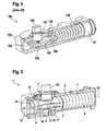
- FIG. 1 A floor spring commonly known from the prior art is shown in figure 1 .
- the floor spring 100 has a piston 101 which is guided in a housing 103.
- Two connecting lugs 104 are connected to the piston 101 such that a movement of the connecting lugs 104 is transferred to piston 101 along the housing 103.
- the floor spring 100 comprises a closer spring 102, which is sandwiched between the piston 101 and the housing 103 around the connecting lugs 104. Therefore, the piston 101 is always subjected to the spring force that changes with the position of the piston 101 that is in turn followed the movement of the connecting lugs 104.
- the floor spring 100 has a spindle 107 which is provided within the housing 103 in perpendicular to the closer spring 102 and the piston 101.
- the spindle 107 has a spindle head 108 protruding outside the housing 103 and functioning as a connecting interface between the floor spring and the door wing. This allows coupling of a door rotation with the spindle 107 via the spindle head 108.
- the spindle 107 comprises a cam surface 106.
- the two connecting lugs 104 are connected via two rollers 105 rolling on the cam surface 106 of the spindle 107.
- both rollers will be in contact with the cam surface 106. Only one roller will be in contact with the cam surface 106 when the spindle 107 is rotating away from the null position.
- the 3 rd roller 105 (close to the spring 102) acts as a safety counter roller.
- the objective of the invention is to provide a floor spring which is easy to assemble, cheap to manufacture and save in operations.
- a floor spring comprising a housing, a first piston, a second piston, and a spindle.
- the spindle extends through an opening of the housing. Further, the spindle is connected to the first piston and the second piston such that a transformation of a longitudinal movement of the first piston and/or second piston into a rotational movement of the spindle is allowed.
- the first piston and the second piston are formed integrally as a hybrid piston, such that both, the first piston and the second piston, are parts of the hybrid piston.
- the first piston and the second piston are assembled within the housing along the same axis.
- the first piston and the second piston are provided along a longitudinal axis of the housing.
- the longitudinal axis intersects with an axis of the spindle.
- the spindle comprises a cam surface to establish a cam drive.
- the spindle is connected to the hybrid piston via said cam drive. Hence, a transformation of the rotation of the spindle into a longitudinal movement of the hybrid piston is provided.
- the first piston has to be pressed against the cam surface of the spindle at all time.
- This assurance is provided by a closer spring sandwiched between an inner wall of the housing and the first piston.
- This design also allows the compression of the closer spring as soon as the spindle is rotated (in the direction of the opening of the door wing) that translates into the linear movement of the first piston.
- this act of compressing of the closer spring presses the first piston via a main roller against the cam surface of the spindle, such that the spindle can be rotated (in the direction of the closing of the door wing) under the force of the loaded closer spring.
- the closer spring is first loaded by manual opening of a door that is connected to the spindle and after which, the closer spring forces the closing of the door by pressing the first piston onto the cam surface of the spindle via the main roller that translates into a turning moment on the spindle.
- the first piston particularly comprises a main roller that rolls on the cam surface of the spindle.
- the second piston comprises the second roller (smaller) that always maintains a very small clearance with the cam surface of the spindle.
- This second roller on the second piston is known as counter roller.
- the second piston may comprise a rolling bolt. The rolling bolt requires less installation space compared with the second counter roller.
- the second piston preferably separates a first fluid chamber from a second fluid chamber within the housing.
- the housing comprises a fluid passage connecting the first fluid chamber and the second fluid chamber.
- a damping system is installed.
- the second piston damps the rotation by the spindle.
- the damping is achieved by the fluid passage, which allows a regulated flow of fluid from the first fluid chamber to the second fluid chamber. Therefore, the speed of the movement of the second piston is strongly determined by the fluid flowing from the first fluid chamber to the second fluid chamber.
- the fluid passage comprises a valve for setting said flow. In case the above mentioned damping system is provided, any rotation of the spindle is damped.
- the second piston preferably comprises a check valve allowing flow of the fluid from the second fluid chamber to the first fluid chamber. Therefore, the door can be opened without damping force, such that the damping system is only active when closing the door.
- the second piston preferably comprises a pressure relief system.
- the pressure relief system is a spring valve. The pressure relief system allows flow of the fluid from the first fluid chamber to the second fluid chamber when a predetermined pressure within the first fluid chamber is exceeded.
- the hybrid piston comprises at least one sealing on the outer surface.
- the sealing seals the hybrid piston against an inner wall of the housing.
- such a sealing is provided in case the housing is made of a less rigid material as plastic.
- the sealing preferably allows an enhanced separation of the first fluid chamber and second fluid chamber.
- the second piston comprises a seal ring and/or the first piston comprises a wear ring.
- the seal ring of the second piston preferably is a combination of a rubber o-ring and polyurethane seal. Therefore, a tight sealing is established.
- a diameter of the spindle and a length of the housing are set at an approximate ratio of 1:8. Additionally or alternatively, the diameter of the spindle and a width of the housing are set at an approximate ratio of 1:3. Yet additionally or alternatively, the diameter of the spindle and a height of the housing are set at an approximate ratio of 1:2.
- the floor spring can supply the same amount of torque provided on the spindle as in the prior art, e.g. for rotating a door. This means that the same door weights as in the prior art can be moved with the inventive floor spring according to the preferred embodiment, while the dimensions of the floor spring are reduced.
- FIG. 2 is a schematic overview of the floor spring 1 according to a first embodiment of the invention.
- the floor spring 1 comprises a housing 2, which is formed to have an at least partly cylindrical inner surface. Therefore, an inner wall 11 of the housing 2 is at least partly formed cylindrically.
- a first piston 3 and a second piston 4 are guided.
- the first piston 3 is a closing piston while the second piston 4 is a damping piston.
- the first piston 3 and the second piston 4 are formed integrally to build a hybrid piston 9.
- the first piston 3 and the second piston 4 are single areas of the hybrid piston 9.
- the hybrid piston 9 as well as the first piston 3 and the second piston 4 are provided along the longitudinal axis 10 of the housing 2.
- the closer spring 8 preferably is a coil spring. In the same way as the hybrid piston 9, the closer spring 8 is orientated along the longitudinal axis 10 of the housing 2.
- the closer spring 8 can be compressed by the movement of the hybrid piston 9.
- the hybrid piston 9 moves to compress the closer spring 8 when a door connected to the floor spring 1 is opened. Thereafter, the energy stored in the closer spring 8 can be used to move the hybrid piston such that the door can be moved back to a closed state.
- the hybrid piston 9 mounted within the housing 2 via an opening of the housing which is closed by an end cap 12.
- the opening also allows mounting of the closer spring 8 within the housing 2.
- the end cap 12 has a thread which is screwed into the housing 2.
- the floor spring 1 In order to connect a door to the floor spring 1, the floor spring 1 comprises a spindle 5 extending through the housing 2.
- the spindle 5 has a spindle head 20 on an area outside the housing 2 such that a door can be connected to that spindle head 20. Since the floor spring 1 is to be provided in a floor of a room, the cam 20 is supposed to function as a lower hinge of the door. In this way, the door can be directly operated without any door operators visible on the door.
- the spindle 5 further has a cam surface 6 which is employed to set up a cam drive between the spindle 5 and the hybrid piston.
- the cam surface 6 is placed between the first piston 3 and the second piston 4. Tight contact of the cam surface 6 and the first piston 3 via the roller 17 is assured under the force of the closer spring 8. Therefore, the hybrid piston 9 can be moved by rotating the spindle 5 and thus the cam surface 6. Accordingly, the cam surface 6 and thus the spindle 5 can be rotated by moving the hybrid piston 9 due to the energy stored by the closer spring 8.
- the second piston 4 functions to damp the movement of the spindle 5. Therefore, the second piston 4 separates a first fluid chamber 14 from a second fluid chamber 15.
- the first fluid chamber 14 is provided between the hybrid piston 9 and the end cap 12.
- a not shown fluid passage within the housing 2 connects the first fluid chamber 14 and the second fluid chamber 15.
- the fluid passage has a regulatory valve to set the flow through the fluid passage.
- the second piston 4 further has a one-way valve 22 (cf. figure 3 ) allowing a fluid provided within the second fluid chamber 15 to flow into the first fluid chamber 14.
- the second piston 4 moves such that the first fluid chamber 14 is enlarged and the second fluid chamber 15 is reduced. This means that fluid flows from the second fluid chamber 15 to the first fluid chamber 14 via the fluid passage of the housing 2 and/or the one-way valve 22 of the second piston 4. In particular, no damping force is generated.
- the hybrid piston 9 and thus the second piston 4 are moved by the cam surface 6 such that the first fluid chamber 14 is reduced and the second fluid chamber 15 is enlarged.
- first piston 3 has a main roller 17 rolling on the cam surface 6.
- the second piston has a second roller 18, the counter roller that under normal operation maintains a small clearance between the counter roller 18 and the cam surface 6. Details of the connection between first piston 3, second piston 4 and cam surface 6 are shown in figure 3 . Due to the main roller 17, the friction generated of the cam surface 6 sliding on the first piston 3 is reduced. Therefore, the floor spring 1 allows opening the door without increased force.
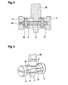
- Figure 4 is a schematic view of a part of the floor spring 1 according to a second embodiment of the invention.
- the second piston 4 does not comprise a second roller 18 but a rolling bolt 19.
- the rolling bolt 19 requires less space within the second piston 4 such that the overall dimensions of the hybrid piston 9 und thus the floor spring 1 can be reduced. Therefore, the second embodiment allows a compact design with a reduced number of components of the floor spring 1.
- figure 5 is a schematic view of a part of the floor spring 1 according to a third embodiment of the invention.
- Figure 5 shows the hybrid piston 9 having provision for additional sealing system.
- Such a sealing system is preferably installed in case the housing 3 is made of less rigid material as plastics.
- the first piston 3 comprises a wear ring 13.
- the second piston 4 comprises a seal ring 21.
- the seal ring 21 is preferably a combination of a rubber o-ring and polyurethane seal. The seal ring 21 assures that the second piston 4 strictly separates the first fluid chamber 14 from the second fluid chamber 15 such that no flow of fluid between the inner wall 11 of the housing 2 and the hybrid piston 9, in particular the second piston 4, is possible.
- the floor spring 1 can comprise a pressure relief system 16.
- the second piston 4 comprises the pressure relief system 16.
- the pressure relief system 16 preferably is a spring valve allowing flow of the fluid from the first fluid chamber 14 to the second fluid chamber 15 when a predetermined fluid pressure within the first fluid chamber 14 is exceeded. Since the second piston 4 does not comprise the second counter roller 18
- the pressure relief system 16 might also be provided with the floor spring 1 according to the second embodiment.
- the overall number of parts is very small compared with the prior art floor spring 100 shown in figure 1 . Therefore, the manufacturing costs and assembly time can be reduced. Additionally, the overall dimensions of the floor spring 1 are reduced compared with the prior art floor spring 100. In particular, the dimension of the cam surface 6 provided on the spindle 5 is reduced. In particular, a diameter of the spindle 5 and a length of the housing 2 are set at an approximate ratio of 1:8. Further, the diameter of the spindle 5 and a width of the housing 2 are set at an approximate ratio of 1:3. Finally, the diameter of the spindle 5 and a height of the housing 2 are set at an approximate ratio of 1:2. Therefore, the floor spring 1 has a very compact design such that less mounting space for the floor spring 1 is required. Nevertheless, the same door weights as in the prior art can be handled by the floor spring 1.
Landscapes
- Closing And Opening Devices For Wings, And Checks For Wings (AREA)
Abstract
Description
- The present invention regards a floor spring. Such floor springs are provided in the floor and function as a door hinge. The door can then be operated by the floor spring directly at the hinge such that no further door operator needs to be mounted on the door itself.
- A floor spring commonly known from the prior art is shown in
figure 1 . Thefloor spring 100 has apiston 101 which is guided in ahousing 103. Two connectinglugs 104 are connected to thepiston 101 such that a movement of the connectinglugs 104 is transferred topiston 101 along thehousing 103. Further, thefloor spring 100 comprises acloser spring 102, which is sandwiched between thepiston 101 and thehousing 103 around the connectinglugs 104. Therefore, thepiston 101 is always subjected to the spring force that changes with the position of thepiston 101 that is in turn followed the movement of the connectinglugs 104. - Finally, the
floor spring 100 has aspindle 107 which is provided within thehousing 103 in perpendicular to thecloser spring 102 and thepiston 101. Thespindle 107 has aspindle head 108 protruding outside thehousing 103 and functioning as a connecting interface between the floor spring and the door wing. This allows coupling of a door rotation with thespindle 107 via thespindle head 108. In order to couple the rotation of thespindle 107 to a movement of thepiston 101, thespindle 107 comprises acam surface 106. On the other side, the two connectinglugs 104 are connected via tworollers 105 rolling on thecam surface 106 of thespindle 107. At null position, both rollers will be in contact with thecam surface 106. Only one roller will be in contact with thecam surface 106 when thespindle 107 is rotating away from the null position. The 3rd roller 105 (close to the spring 102) acts as a safety counter roller. - In case a door wing connected to the
spindle 107 is rotated in the manner to open the door wing, thecam surface 106 and one of the rollers105 (far from the spring 102) convert the rotation of thespindle 107 into a linear movement of the connectinglugs 104 and in turn pulls thepiston 101 towards thespindle 107. This results in a compression of thecloser spring 102 by the movement of thepiston 101. Therefore, thefloor spring 100 is loaded with energy to move the door wing back to the original position i.e. closing of the door wing. - However, the above described prior
art floor spring 100 requires a lot of components for manufacturing. This results in high costs due to material usage of individual components a long assembly time due to complexity of assembly. - Therefore, the objective of the invention is to provide a floor spring which is easy to assemble, cheap to manufacture and save in operations.
- The result of this objective is achieved by the features of independent claim 1. Therefore, the object is solved by a floor spring comprising a housing, a first piston, a second piston, and a spindle. The spindle extends through an opening of the housing. Further, the spindle is connected to the first piston and the second piston such that a transformation of a longitudinal movement of the first piston and/or second piston into a rotational movement of the spindle is allowed. The first piston and the second piston are formed integrally as a hybrid piston, such that both, the first piston and the second piston, are parts of the hybrid piston. By providing such a floor spring, the number of parts required for assembling is reduced. This results in a simplified assembly procedure thus such the inventive floor spring can be manufactured cheaper than the prior art floor springs. Also, the overall dimensions of the inventive floor spring can be reduced due to the compactness of the cam driven system with hybrid piston.
- The dependent claims contain advantageous embodiments of the present invention.
- Preferably, the first piston and the second piston are assembled within the housing along the same axis. In particular, the first piston and the second piston are provided along a longitudinal axis of the housing. In particular, the longitudinal axis intersects with an axis of the spindle.
- In particular, the spindle comprises a cam surface to establish a cam drive. The spindle is connected to the hybrid piston via said cam drive. Hence, a transformation of the rotation of the spindle into a longitudinal movement of the hybrid piston is provided.
- In order to achieve a reliable transformation between rotation of the spindle and longitudinal movement of the hybrid piston, the first piston has to be pressed against the cam surface of the spindle at all time. This assurance is provided by a closer spring sandwiched between an inner wall of the housing and the first piston. This design also allows the compression of the closer spring as soon as the spindle is rotated (in the direction of the opening of the door wing) that translates into the linear movement of the first piston. On the other side, this act of compressing of the closer spring presses the first piston via a main roller against the cam surface of the spindle, such that the spindle can be rotated (in the direction of the closing of the door wing) under the force of the loaded closer spring. In particular, the closer spring is first loaded by manual opening of a door that is connected to the spindle and after which, the closer spring forces the closing of the door by pressing the first piston onto the cam surface of the spindle via the main roller that translates into a turning moment on the spindle.
- The first piston particularly comprises a main roller that rolls on the cam surface of the spindle. In the same way, the second piston comprises the second roller (smaller) that always maintains a very small clearance with the cam surface of the spindle. This second roller on the second piston is known as counter roller. Alternatively, instead of a second roller, the second piston may comprise a rolling bolt. The rolling bolt requires less installation space compared with the second counter roller.
- The second piston preferably separates a first fluid chamber from a second fluid chamber within the housing. The housing comprises a fluid passage connecting the first fluid chamber and the second fluid chamber. In this way, a damping system is installed. When moving the second piston due to rotation of the spindle caused by the closer spring pressing the first piston against the cam surface, the second piston damps the rotation by the spindle. The damping is achieved by the fluid passage, which allows a regulated flow of fluid from the first fluid chamber to the second fluid chamber. Therefore, the speed of the movement of the second piston is strongly determined by the fluid flowing from the first fluid chamber to the second fluid chamber. Preferably, the fluid passage comprises a valve for setting said flow. In case the above mentioned damping system is provided, any rotation of the spindle is damped. This would result in an activation of the damping during the opening of the door which would cause an uncomfortable handling of the door. To avoid such drawbacks, the second piston preferably comprises a check valve allowing flow of the fluid from the second fluid chamber to the first fluid chamber. Therefore, the door can be opened without damping force, such that the damping system is only active when closing the door.
- Additionally, there might be the case that the door is forcibly closed by a user while the damping system exerting a damping force. This might cause a huge pressure within the first fluid chamber and the fluid passage. In order to prevent damage of the floor spring, the second piston preferably comprises a pressure relief system. In particular, the pressure relief system is a spring valve. The pressure relief system allows flow of the fluid from the first fluid chamber to the second fluid chamber when a predetermined pressure within the first fluid chamber is exceeded.
- In a preferred embodiment, the hybrid piston comprises at least one sealing on the outer surface. The sealing seals the hybrid piston against an inner wall of the housing. In particular, such a sealing is provided in case the housing is made of a less rigid material as plastic. The sealing preferably allows an enhanced separation of the first fluid chamber and second fluid chamber.
- In particular, the second piston comprises a seal ring and/or the first piston comprises a wear ring. The seal ring of the second piston preferably is a combination of a rubber o-ring and polyurethane seal. Therefore, a tight sealing is established.
- In a preferred embodiment, a diameter of the spindle and a length of the housing are set at an approximate ratio of 1:8. Additionally or alternatively, the diameter of the spindle and a width of the housing are set at an approximate ratio of 1:3. Yet additionally or alternatively, the diameter of the spindle and a height of the housing are set at an approximate ratio of 1:2. This allows a compact design of the floor spring. Despite the compact design, the floor spring can supply the same amount of torque provided on the spindle as in the prior art, e.g. for rotating a door. This means that the same door weights as in the prior art can be moved with the inventive floor spring according to the preferred embodiment, while the dimensions of the floor spring are reduced.
- Particular embodiments of the invention are now described based on the attached drawings. In the drawings,
- Fig. 1
- is a schematic overview of the floor spring according to the prior art,
- Fig. 2
- is a schematic overview of the floor spring according to a first embodiment of the present invention,
- Fig. 3
- is a schematic view of a part of the floor spring according to the first embodiment of the present invention,
- Fig. 4
- is a schematic view of a part of the floor spring according to a second embodiment of the present invention, and
- Fig. 5
- is a schematic view of a part of the floor spring according to a third embodiment of the present invention.
-
Figure 2 is a schematic overview of the floor spring 1 according to a first embodiment of the invention. The floor spring 1 comprises ahousing 2, which is formed to have an at least partly cylindrical inner surface. Therefore, aninner wall 11 of thehousing 2 is at least partly formed cylindrically. In thehousing 2, afirst piston 3 and asecond piston 4 are guided. In particular, thefirst piston 3 is a closing piston while thesecond piston 4 is a damping piston. Thefirst piston 3 and thesecond piston 4 are formed integrally to build ahybrid piston 9. In other words, thefirst piston 3 and thesecond piston 4 are single areas of thehybrid piston 9. Thehybrid piston 9 as well as thefirst piston 3 and thesecond piston 4 are provided along thelongitudinal axis 10 of thehousing 2. - Between the
inner wall 11 of thehousing 2 and thehybrid piston 9, in particular thefirst piston 3, a closer spring 8 is sandwiched. The closer spring 8 preferably is a coil spring. In the same way as thehybrid piston 9, the closer spring 8 is orientated along thelongitudinal axis 10 of thehousing 2. - The closer spring 8 can be compressed by the movement of the
hybrid piston 9. In particular, thehybrid piston 9 moves to compress the closer spring 8 when a door connected to the floor spring 1 is opened. Thereafter, the energy stored in the closer spring 8 can be used to move the hybrid piston such that the door can be moved back to a closed state. - The
hybrid piston 9 mounted within thehousing 2 via an opening of the housing which is closed by anend cap 12. The opening also allows mounting of the closer spring 8 within thehousing 2. In particular, theend cap 12 has a thread which is screwed into thehousing 2. - In order to connect a door to the floor spring 1, the floor spring 1 comprises a
spindle 5 extending through thehousing 2. Thespindle 5 has aspindle head 20 on an area outside thehousing 2 such that a door can be connected to thatspindle head 20. Since the floor spring 1 is to be provided in a floor of a room, thecam 20 is supposed to function as a lower hinge of the door. In this way, the door can be directly operated without any door operators visible on the door. - The
spindle 5 further has acam surface 6 which is employed to set up a cam drive between thespindle 5 and the hybrid piston. In particular, thecam surface 6 is placed between thefirst piston 3 and thesecond piston 4. Tight contact of thecam surface 6 and thefirst piston 3 via theroller 17 is assured under the force of the closer spring 8. Therefore, thehybrid piston 9 can be moved by rotating thespindle 5 and thus thecam surface 6. Accordingly, thecam surface 6 and thus thespindle 5 can be rotated by moving thehybrid piston 9 due to the energy stored by the closer spring 8. - In case the door is opened, the movement of the door is transferred to the
spindle 5 via thespindle head 20. Therefore, thespindle 5 and thus thecam surface 6 are rotated. The rotation of thecam surface 6 causes thehybrid piston 9 to be moved such that the closer spring 8 is compressed. In this way, energy is stored within the closer spring 8 such that the closer spring 8 is enabled to move thehybrid piston 9. Due to the movement of thehybrid piston 9, thecam surface 6 and thus thespindle 5 are rotated. This rotation is transferred to the door via thespindle head 20 such that the door is moved back to the closed state. - The
second piston 4 functions to damp the movement of thespindle 5. Therefore, thesecond piston 4 separates afirst fluid chamber 14 from asecond fluid chamber 15. In particular, thefirst fluid chamber 14 is provided between thehybrid piston 9 and theend cap 12. A not shown fluid passage within thehousing 2 connects thefirst fluid chamber 14 and thesecond fluid chamber 15. In particular, the fluid passage has a regulatory valve to set the flow through the fluid passage. Thesecond piston 4 further has a one-way valve 22 (cf.figure 3 ) allowing a fluid provided within thesecond fluid chamber 15 to flow into thefirst fluid chamber 14. - In case the door is opened, the
second piston 4 moves such that thefirst fluid chamber 14 is enlarged and thesecond fluid chamber 15 is reduced. This means that fluid flows from thesecond fluid chamber 15 to thefirst fluid chamber 14 via the fluid passage of thehousing 2 and/or the one-way valve 22 of thesecond piston 4. In particular, no damping force is generated. - In case the door is closed by the closer spring 8, the
hybrid piston 9 and thus thesecond piston 4 are moved by thecam surface 6 such that thefirst fluid chamber 14 is reduced and thesecond fluid chamber 15 is enlarged. This means that fluid flows from thefirst fluid chamber 14 to thesecond fluid chamber 15 via the fluid passage of thehousing 2. Since the maximum flow of the fluid can be changed by the valve provided within the fluid passage, a user settable damping force is generated. The damping force prevents the door from being slammed against the door frame. - Further, the
first piston 3 has amain roller 17 rolling on thecam surface 6. The second piston has asecond roller 18, the counter roller that under normal operation maintains a small clearance between thecounter roller 18 and thecam surface 6. Details of the connection betweenfirst piston 3,second piston 4 andcam surface 6 are shown infigure 3 . Due to themain roller 17, the friction generated of thecam surface 6 sliding on thefirst piston 3 is reduced. Therefore, the floor spring 1 allows opening the door without increased force. -
Figure 4 is a schematic view of a part of the floor spring 1 according to a second embodiment of the invention. In the second embodiment, the only difference to the first embodiment is that thesecond piston 4 does not comprise asecond roller 18 but a rollingbolt 19. The rollingbolt 19 requires less space within thesecond piston 4 such that the overall dimensions of thehybrid piston 9 und thus the floor spring 1 can be reduced. Therefore, the second embodiment allows a compact design with a reduced number of components of the floor spring 1. - Finally,
figure 5 is a schematic view of a part of the floor spring 1 according to a third embodiment of the invention.Figure 5 shows thehybrid piston 9 having provision for additional sealing system. Such a sealing system is preferably installed in case thehousing 3 is made of less rigid material as plastics. - The
first piston 3 comprises awear ring 13. On the other side, thesecond piston 4 comprises aseal ring 21. Theseal ring 21 is preferably a combination of a rubber o-ring and polyurethane seal. Theseal ring 21 assures that thesecond piston 4 strictly separates thefirst fluid chamber 14 from thesecond fluid chamber 15 such that no flow of fluid between theinner wall 11 of thehousing 2 and thehybrid piston 9, in particular thesecond piston 4, is possible. - Additionally, in the third embodiment, the floor spring 1 can comprise a
pressure relief system 16. There might be the case that the door is closed manually such that both, the force of the closer spring 8 and the force of a user trying to close the door act on thehybrid piston 9. Therefore, the pressure within thefirst fluid chamber 14 and the fluid passage increases. In order to prevent damage caused due to high fluid pressure, thesecond piston 4 comprises thepressure relief system 16. Thepressure relief system 16 preferably is a spring valve allowing flow of the fluid from thefirst fluid chamber 14 to thesecond fluid chamber 15 when a predetermined fluid pressure within thefirst fluid chamber 14 is exceeded. Since thesecond piston 4 does not comprise thesecond counter roller 18 - (first embodiment) but rather the rolling bolt 19 (second embodiment), there is enough room left within the
second piston 4 to provide thepressure relief system 16. Therefore, thepressure relief system 16 might also be provided with the floor spring 1 according to the second embodiment. - Regarding all embodiments, it can be seen, that the overall number of parts is very small compared with the prior
art floor spring 100 shown infigure 1 . Therefore, the manufacturing costs and assembly time can be reduced. Additionally, the overall dimensions of the floor spring 1 are reduced compared with the priorart floor spring 100. In particular, the dimension of thecam surface 6 provided on thespindle 5 is reduced. In particular, a diameter of thespindle 5 and a length of thehousing 2 are set at an approximate ratio of 1:8. Further, the diameter of thespindle 5 and a width of thehousing 2 are set at an approximate ratio of 1:3. Finally, the diameter of thespindle 5 and a height of thehousing 2 are set at an approximate ratio of 1:2. Therefore, the floor spring 1 has a very compact design such that less mounting space for the floor spring 1 is required. Nevertheless, the same door weights as in the prior art can be handled by the floor spring 1. -
- 1
- floor spring
- 2
- housing
- 3
- first piston
- 4
- second piston
- 5
- spindle
- 6
- cam surface
- 7
- opening of the housing
- 8
- closer spring
- 9
- hybrid piston
- 10
- longitudinal axis of the housing
- 11
- inner wall of housing
- 12
- end cap
- 13
- wear ring
- 14
- first fluid chamber
- 15
- second fluid chamber
- 16
- pressure relief system
- 17
- main roller
- 18
- counter roller
- 19
- rolling bolt
- 20
- spindle head
- 21
- seal ring
- 100
- floor spring (prior art)
- 101
- piston (prior art)
- 102
- closer spring (prior art)
- 103
- housing (prior art)
- 104
- connecting lug (prior art)
- 105
- roller (prior art)
- 106
- cam surface (prior art)
- 107
- spindle (prior art)
- 108
- spindle head (prior art)
Claims (10)
- Floor spring (1), comprising- a housing (2),- a first piston (3),- a second piston (4), and- a spindle (5) extending through an opening (7) of the housing (2),- wherein the spindle (5) is connected to the first piston (3) such that a longitudinal movement of the first piston (3) is translated into a rotational movement of the spindle (5) via the main roller (17), and- wherein the first piston (3) and the second piston (4) are formed integrally as a hybrid piston (9).
- Floor spring (1) according to claim 1, characterized in that the first piston (3) and the second piston (4) are provided within the housing (2) along the same axis (10).
- Floor spring (1) according to any one of previous claims, characterized in that the spindle (5) comprises a cam surface (6), wherein the spindle (5) is connected to the first piston (3) via the main roller (17) and the cam surface (6) to establish the cam driven mechanism.
- Floor spring (1) according claim 3, characterized by a closer spring (8) provided between an inner wall (11) of the housing (2) and the first piston (3), such that the first piston (3) is pressed against the cam surface (6) of the spindle (5) via the main roller (17).
- Floor spring (1) according to claim 3 or 4, characterized in that the first piston (3) comprises a main roller (17) rolling on the cam surface (6) of the spindle (5) and/or the second piston (4) comprises a counter roller (18) or a rolling bolt (19) that maintains a small clearance with the cam surface (6) of the spindle (5) under normal operating condition.
- Floor spring (1) according to any one of previous claims, characterized in that the second piston (4) separates a first fluid chamber (14) from a second fluid chamber (15) within the housing (2), wherein the housing (2) comprises a fluid passage connecting the first fluid chamber (14) and the second fluid chamber (15).
- Floor spring according to claim 6, characterized in that the second piston (4) comprises a pressure relief system (16), in particular a spring valve, allowing flow of a fluid from the first fluid chamber (14) to the second fluid chamber (15) when a predetermined pressure within the first fluid chamber (14) is exceeded.
- Floor spring (1) according to any one of previous claims, characterized in that the hybrid piston (9) comprises one seal ring (21) on the outer surface to seal the hybrid piston (9) against an inner wall (11) of the housing (2).
- Floor spring (1) according to claim 8, characterized in that the second piston (4) comprises a seal ring (21), in particular a combination of a rubber o-ring and polyurethane seal, and/or the first piston (3) comprises a wear ring (13).
- Floor spring (1) according to any one of previous claims, characterized in that- a diameter of the spindle (5) and a length of the housing (2) are set at an approximate ratio of 1:8 and/or- a diameter of the spindle (5) and a width of the housing (2) are set at an approximate ratio of 1:3 and/or- a diameter of the spindle (5) and a height of the housing (2) are set at an approximate ratio of 1:2.
Priority Applications (2)
| Application Number | Priority Date | Filing Date | Title |
|---|---|---|---|
| EP14196668.9A EP3029252A1 (en) | 2014-12-05 | 2014-12-05 | Floor door closer |
| CN201510779366.8A CN105672799A (en) | 2014-12-05 | 2015-11-13 | Floor spring |
Applications Claiming Priority (1)
| Application Number | Priority Date | Filing Date | Title |
|---|---|---|---|
| EP14196668.9A EP3029252A1 (en) | 2014-12-05 | 2014-12-05 | Floor door closer |
Publications (1)
| Publication Number | Publication Date |
|---|---|
| EP3029252A1 true EP3029252A1 (en) | 2016-06-08 |
Family
ID=52011072
Family Applications (1)
| Application Number | Title | Priority Date | Filing Date |
|---|---|---|---|
| EP14196668.9A Withdrawn EP3029252A1 (en) | 2014-12-05 | 2014-12-05 | Floor door closer |
Country Status (2)
| Country | Link |
|---|---|
| EP (1) | EP3029252A1 (en) |
| CN (1) | CN105672799A (en) |
Families Citing this family (3)
| Publication number | Priority date | Publication date | Assignee | Title |
|---|---|---|---|---|
| CN106978951B (en) * | 2016-09-19 | 2019-05-10 | 上海品贵国际贸易有限公司 | Arbor automatic homing device with deceleration or rate controlling function |
| CN106761106A (en) * | 2016-12-27 | 2017-05-31 | 佛山市奥达金属制品有限公司 | Configurable parted hair formula cam gear |
| EP3401485B1 (en) * | 2017-05-12 | 2020-07-01 | dormakaba Deutschland GmbH | Door actuator |
Citations (2)
| Publication number | Priority date | Publication date | Assignee | Title |
|---|---|---|---|---|
| US5901412A (en) * | 1996-01-30 | 1999-05-11 | Dorma Gmbh + Co. Kg | Top-mounted door closer |
| EP2138662A2 (en) * | 2008-06-27 | 2009-12-30 | Taiwan Fu Hsing Industrial Co. Ltd. | Automatic door closer |
Family Cites Families (5)
| Publication number | Priority date | Publication date | Assignee | Title |
|---|---|---|---|---|
| IT251019Y1 (en) * | 2000-03-13 | 2003-11-04 | Fev Italia Archal S R L | AIR DOOR CLOSER PROVIDED WITH PERFECT ROTATION VEHICLES. |
| CN101135219B (en) * | 2006-09-01 | 2012-11-14 | 多玛两合有限公司 | Door closer |
| KR101061898B1 (en) * | 2009-03-05 | 2011-09-05 | 박형태 | Floor hinge assembly |
| DE102011055974A1 (en) * | 2011-12-02 | 2013-06-06 | Dorma Gmbh + Co. Kg | door actuators |
| CN202645244U (en) * | 2012-04-16 | 2013-01-02 | 肇庆市志盛门控五金有限公司 | Concealed door closer |
-
2014
- 2014-12-05 EP EP14196668.9A patent/EP3029252A1/en not_active Withdrawn
-
2015
- 2015-11-13 CN CN201510779366.8A patent/CN105672799A/en active Pending
Patent Citations (2)
| Publication number | Priority date | Publication date | Assignee | Title |
|---|---|---|---|---|
| US5901412A (en) * | 1996-01-30 | 1999-05-11 | Dorma Gmbh + Co. Kg | Top-mounted door closer |
| EP2138662A2 (en) * | 2008-06-27 | 2009-12-30 | Taiwan Fu Hsing Industrial Co. Ltd. | Automatic door closer |
Also Published As
| Publication number | Publication date |
|---|---|
| CN105672799A (en) | 2016-06-15 |
Similar Documents
| Publication | Publication Date | Title |
|---|---|---|
| KR101418582B1 (en) | Door closure | |
| US9181744B2 (en) | Door actuator | |
| US20130081227A1 (en) | Door closer | |
| EP0544253B1 (en) | Damper and method of controlling a door | |
| JP5555198B2 (en) | Door closer | |
| US9416578B2 (en) | Door closer | |
| TWI421426B (en) | Electric needle valve | |
| EP3455440B1 (en) | Hinge for the rotatable movement of a door, a shutter or the like | |
| EP2902576A1 (en) | Door closer | |
| US20030093872A1 (en) | Door closer | |
| WO2017054621A1 (en) | Hinge with detachable damper | |
| EP3029253A1 (en) | Floor door closer | |
| KR102094189B1 (en) | Door closer | |
| TW201303129A (en) | Door hinge including a damping system | |
| JP5702668B2 (en) | Door closer | |
| EP3284986B1 (en) | Thermal volume control for an actuator assembly | |
| CN105672799A (en) | Floor spring | |
| KR101761827B1 (en) | The actuator | |
| JP6178083B2 (en) | Door closer | |
| CN102959168B (en) | door closer | |
| US8776963B2 (en) | Device for damping the movement of a body at the end of travel | |
| CN103697204B (en) | There is the outlet valve of emergency shutdown function | |
| US20200370659A1 (en) | Rotary valve | |
| CN111677922B (en) | Safety valve | |
| KR20200014996A (en) | Door closer |
Legal Events
| Date | Code | Title | Description |
|---|---|---|---|
| PUAI | Public reference made under article 153(3) epc to a published international application that has entered the european phase |
Free format text: ORIGINAL CODE: 0009012 |
|
| AK | Designated contracting states |
Kind code of ref document: A1 Designated state(s): AL AT BE BG CH CY CZ DE DK EE ES FI FR GB GR HR HU IE IS IT LI LT LU LV MC MK MT NL NO PL PT RO RS SE SI SK SM TR |
|
| AX | Request for extension of the european patent |
Extension state: BA ME |
|
| STAA | Information on the status of an ep patent application or granted ep patent |
Free format text: STATUS: REQUEST FOR EXAMINATION WAS MADE |
|
| 17P | Request for examination filed |
Effective date: 20161207 |
|
| RAP1 | Party data changed (applicant data changed or rights of an application transferred) |
Owner name: DORMAKABA DEUTSCHLAND GMBH |
|
| RBV | Designated contracting states (corrected) |
Designated state(s): AL AT BE BG CH CY CZ DE DK EE ES FI FR GB GR HR HU IE IS IT LI LT LU LV MC MK MT NL NO PL PT RO RS SE SI SK SM TR |
|
| STAA | Information on the status of an ep patent application or granted ep patent |
Free format text: STATUS: EXAMINATION IS IN PROGRESS |
|
| 17Q | First examination report despatched |
Effective date: 20180309 |
|
| STAA | Information on the status of an ep patent application or granted ep patent |
Free format text: STATUS: THE APPLICATION IS DEEMED TO BE WITHDRAWN |
|
| 18D | Application deemed to be withdrawn |
Effective date: 20180920 |