EP3028879A1 - Steer axle high-temperature warning system - Google Patents
Steer axle high-temperature warning system Download PDFInfo
- Publication number
- EP3028879A1 EP3028879A1 EP16151339.5A EP16151339A EP3028879A1 EP 3028879 A1 EP3028879 A1 EP 3028879A1 EP 16151339 A EP16151339 A EP 16151339A EP 3028879 A1 EP3028879 A1 EP 3028879A1
- Authority
- EP
- European Patent Office
- Prior art keywords
- steer
- normally
- closed valve
- axle spindle
- channel
- Prior art date
- Legal status (The legal status is an assumption and is not a legal conclusion. Google has not performed a legal analysis and makes no representation as to the accuracy of the status listed.)
- Withdrawn
Links
Images


Classifications
-
- B—PERFORMING OPERATIONS; TRANSPORTING
- B60—VEHICLES IN GENERAL
- B60C—VEHICLE TYRES; TYRE INFLATION; TYRE CHANGING; CONNECTING VALVES TO INFLATABLE ELASTIC BODIES IN GENERAL; DEVICES OR ARRANGEMENTS RELATED TO TYRES
- B60C23/00—Devices for measuring, signalling, controlling, or distributing tyre pressure or temperature, specially adapted for mounting on vehicles; Arrangement of tyre inflating devices on vehicles, e.g. of pumps or of tanks; Tyre cooling arrangements
-
- B—PERFORMING OPERATIONS; TRANSPORTING
- B60—VEHICLES IN GENERAL
- B60B—VEHICLE WHEELS; CASTORS; AXLES FOR WHEELS OR CASTORS; INCREASING WHEEL ADHESION
- B60B35/00—Axle units; Parts thereof ; Arrangements for lubrication of axles
- B60B35/003—Steerable axles
-
- B—PERFORMING OPERATIONS; TRANSPORTING
- B60—VEHICLES IN GENERAL
- B60C—VEHICLE TYRES; TYRE INFLATION; TYRE CHANGING; CONNECTING VALVES TO INFLATABLE ELASTIC BODIES IN GENERAL; DEVICES OR ARRANGEMENTS RELATED TO TYRES
- B60C23/00—Devices for measuring, signalling, controlling, or distributing tyre pressure or temperature, specially adapted for mounting on vehicles; Arrangement of tyre inflating devices on vehicles, e.g. of pumps or of tanks; Tyre cooling arrangements
- B60C23/001—Devices for manually or automatically controlling or distributing tyre pressure whilst the vehicle is moving
- B60C23/002—Devices for manually or automatically controlling or distributing tyre pressure whilst the vehicle is moving by monitoring conditions other than tyre pressure or deformation
-
- B—PERFORMING OPERATIONS; TRANSPORTING
- B60—VEHICLES IN GENERAL
- B60C—VEHICLE TYRES; TYRE INFLATION; TYRE CHANGING; CONNECTING VALVES TO INFLATABLE ELASTIC BODIES IN GENERAL; DEVICES OR ARRANGEMENTS RELATED TO TYRES
- B60C23/00—Devices for measuring, signalling, controlling, or distributing tyre pressure or temperature, specially adapted for mounting on vehicles; Arrangement of tyre inflating devices on vehicles, e.g. of pumps or of tanks; Tyre cooling arrangements
- B60C23/001—Devices for manually or automatically controlling or distributing tyre pressure whilst the vehicle is moving
- B60C23/003—Devices for manually or automatically controlling or distributing tyre pressure whilst the vehicle is moving comprising rotational joints between vehicle-mounted pressure sources and the tyres
- B60C23/00309—Devices for manually or automatically controlling or distributing tyre pressure whilst the vehicle is moving comprising rotational joints between vehicle-mounted pressure sources and the tyres characterised by the location of the components, e.g. valves, sealings, conduits or sensors
- B60C23/00336—Devices for manually or automatically controlling or distributing tyre pressure whilst the vehicle is moving comprising rotational joints between vehicle-mounted pressure sources and the tyres characterised by the location of the components, e.g. valves, sealings, conduits or sensors on the axles
-
- B—PERFORMING OPERATIONS; TRANSPORTING
- B60—VEHICLES IN GENERAL
- B60C—VEHICLE TYRES; TYRE INFLATION; TYRE CHANGING; CONNECTING VALVES TO INFLATABLE ELASTIC BODIES IN GENERAL; DEVICES OR ARRANGEMENTS RELATED TO TYRES
- B60C23/00—Devices for measuring, signalling, controlling, or distributing tyre pressure or temperature, specially adapted for mounting on vehicles; Arrangement of tyre inflating devices on vehicles, e.g. of pumps or of tanks; Tyre cooling arrangements
- B60C23/001—Devices for manually or automatically controlling or distributing tyre pressure whilst the vehicle is moving
- B60C23/003—Devices for manually or automatically controlling or distributing tyre pressure whilst the vehicle is moving comprising rotational joints between vehicle-mounted pressure sources and the tyres
- B60C23/00354—Details of valves
-
- B—PERFORMING OPERATIONS; TRANSPORTING
- B60—VEHICLES IN GENERAL
- B60C—VEHICLE TYRES; TYRE INFLATION; TYRE CHANGING; CONNECTING VALVES TO INFLATABLE ELASTIC BODIES IN GENERAL; DEVICES OR ARRANGEMENTS RELATED TO TYRES
- B60C23/00—Devices for measuring, signalling, controlling, or distributing tyre pressure or temperature, specially adapted for mounting on vehicles; Arrangement of tyre inflating devices on vehicles, e.g. of pumps or of tanks; Tyre cooling arrangements
- B60C23/001—Devices for manually or automatically controlling or distributing tyre pressure whilst the vehicle is moving
- B60C23/003—Devices for manually or automatically controlling or distributing tyre pressure whilst the vehicle is moving comprising rotational joints between vehicle-mounted pressure sources and the tyres
- B60C23/00363—Details of sealings
-
- B—PERFORMING OPERATIONS; TRANSPORTING
- B60—VEHICLES IN GENERAL
- B60C—VEHICLE TYRES; TYRE INFLATION; TYRE CHANGING; CONNECTING VALVES TO INFLATABLE ELASTIC BODIES IN GENERAL; DEVICES OR ARRANGEMENTS RELATED TO TYRES
- B60C23/00—Devices for measuring, signalling, controlling, or distributing tyre pressure or temperature, specially adapted for mounting on vehicles; Arrangement of tyre inflating devices on vehicles, e.g. of pumps or of tanks; Tyre cooling arrangements
- B60C23/001—Devices for manually or automatically controlling or distributing tyre pressure whilst the vehicle is moving
- B60C23/003—Devices for manually or automatically controlling or distributing tyre pressure whilst the vehicle is moving comprising rotational joints between vehicle-mounted pressure sources and the tyres
- B60C23/00381—Devices for manually or automatically controlling or distributing tyre pressure whilst the vehicle is moving comprising rotational joints between vehicle-mounted pressure sources and the tyres specially adapted for steerable wheels
-
- B—PERFORMING OPERATIONS; TRANSPORTING
- B60—VEHICLES IN GENERAL
- B60C—VEHICLE TYRES; TYRE INFLATION; TYRE CHANGING; CONNECTING VALVES TO INFLATABLE ELASTIC BODIES IN GENERAL; DEVICES OR ARRANGEMENTS RELATED TO TYRES
- B60C23/00—Devices for measuring, signalling, controlling, or distributing tyre pressure or temperature, specially adapted for mounting on vehicles; Arrangement of tyre inflating devices on vehicles, e.g. of pumps or of tanks; Tyre cooling arrangements
- B60C23/20—Devices for measuring or signalling tyre temperature only
-
- B—PERFORMING OPERATIONS; TRANSPORTING
- B60—VEHICLES IN GENERAL
- B60C—VEHICLE TYRES; TYRE INFLATION; TYRE CHANGING; CONNECTING VALVES TO INFLATABLE ELASTIC BODIES IN GENERAL; DEVICES OR ARRANGEMENTS RELATED TO TYRES
- B60C29/00—Arrangements of tyre-inflating valves to tyres or rims; Accessories for tyre-inflating valves, not otherwise provided for
- B60C29/06—Accessories for tyre-inflating valves, e.g. housings, guards, covers for valve caps, locks, not otherwise provided for
-
- B—PERFORMING OPERATIONS; TRANSPORTING
- B60—VEHICLES IN GENERAL
- B60T—VEHICLE BRAKE CONTROL SYSTEMS OR PARTS THEREOF; BRAKE CONTROL SYSTEMS OR PARTS THEREOF, IN GENERAL; ARRANGEMENT OF BRAKING ELEMENTS ON VEHICLES IN GENERAL; PORTABLE DEVICES FOR PREVENTING UNWANTED MOVEMENT OF VEHICLES; VEHICLE MODIFICATIONS TO FACILITATE COOLING OF BRAKES
- B60T17/00—Component parts, details, or accessories of power brake systems not covered by groups B60T8/00, B60T13/00 or B60T15/00, or presenting other characteristic features
- B60T17/18—Safety devices; Monitoring
- B60T17/22—Devices for monitoring or checking brake systems; Signal devices
-
- B—PERFORMING OPERATIONS; TRANSPORTING
- B60—VEHICLES IN GENERAL
- B60T—VEHICLE BRAKE CONTROL SYSTEMS OR PARTS THEREOF; BRAKE CONTROL SYSTEMS OR PARTS THEREOF, IN GENERAL; ARRANGEMENT OF BRAKING ELEMENTS ON VEHICLES IN GENERAL; PORTABLE DEVICES FOR PREVENTING UNWANTED MOVEMENT OF VEHICLES; VEHICLE MODIFICATIONS TO FACILITATE COOLING OF BRAKES
- B60T5/00—Vehicle modifications to facilitate cooling of brakes
-
- F—MECHANICAL ENGINEERING; LIGHTING; HEATING; WEAPONS; BLASTING
- F16—ENGINEERING ELEMENTS AND UNITS; GENERAL MEASURES FOR PRODUCING AND MAINTAINING EFFECTIVE FUNCTIONING OF MACHINES OR INSTALLATIONS; THERMAL INSULATION IN GENERAL
- F16K—VALVES; TAPS; COCKS; ACTUATING-FLOATS; DEVICES FOR VENTING OR AERATING
- F16K17/00—Safety valves; Equalising valves, e.g. pressure relief valves
- F16K17/36—Safety valves; Equalising valves, e.g. pressure relief valves actuated in consequence of extraneous circumstances, e.g. shock, change of position
- F16K17/38—Safety valves; Equalising valves, e.g. pressure relief valves actuated in consequence of extraneous circumstances, e.g. shock, change of position of excessive temperature
- F16K17/383—Safety valves; Equalising valves, e.g. pressure relief valves actuated in consequence of extraneous circumstances, e.g. shock, change of position of excessive temperature the valve comprising fusible, softening or meltable elements, e.g. used as link, blocking element, seal, closure plug
-
- B—PERFORMING OPERATIONS; TRANSPORTING
- B60—VEHICLES IN GENERAL
- B60B—VEHICLE WHEELS; CASTORS; AXLES FOR WHEELS OR CASTORS; INCREASING WHEEL ADHESION
- B60B2900/00—Purpose of invention
- B60B2900/70—Adaptation for
- B60B2900/731—Use in cases of damage, failure or emergency
-
- Y—GENERAL TAGGING OF NEW TECHNOLOGICAL DEVELOPMENTS; GENERAL TAGGING OF CROSS-SECTIONAL TECHNOLOGIES SPANNING OVER SEVERAL SECTIONS OF THE IPC; TECHNICAL SUBJECTS COVERED BY FORMER USPC CROSS-REFERENCE ART COLLECTIONS [XRACs] AND DIGESTS
- Y10—TECHNICAL SUBJECTS COVERED BY FORMER USPC
- Y10T—TECHNICAL SUBJECTS COVERED BY FORMER US CLASSIFICATION
- Y10T137/00—Fluid handling
- Y10T137/1624—Destructible or deformable element controlled
- Y10T137/1797—Heat destructible or fusible
-
- Y—GENERAL TAGGING OF NEW TECHNOLOGICAL DEVELOPMENTS; GENERAL TAGGING OF CROSS-SECTIONAL TECHNOLOGIES SPANNING OVER SEVERAL SECTIONS OF THE IPC; TECHNICAL SUBJECTS COVERED BY FORMER USPC CROSS-REFERENCE ART COLLECTIONS [XRACs] AND DIGESTS
- Y10—TECHNICAL SUBJECTS COVERED BY FORMER USPC
- Y10T—TECHNICAL SUBJECTS COVERED BY FORMER US CLASSIFICATION
- Y10T137/00—Fluid handling
- Y10T137/8158—With indicator, register, recorder, alarm or inspection means
- Y10T137/8326—Fluid pressure responsive indicator, recorder or alarm
Landscapes
- Engineering & Computer Science (AREA)
- Mechanical Engineering (AREA)
- Transportation (AREA)
- General Engineering & Computer Science (AREA)
- Rolling Contact Bearings (AREA)
- Valves And Accessory Devices For Braking Systems (AREA)
- Vehicle Body Suspensions (AREA)
- Sealing Devices (AREA)
- Safety Valves (AREA)
- Tires In General (AREA)
Abstract
Description
- This application claims priority to
U.S. Provisional Patent Application No. 61/368,960 - The disclosed system relates generally to high temperature warning systems for vehicle steer axles.
- In the event of a failure associated with the wheel end, such as a bearing failure or brake failure, elements of the wheel end can heat up and reach high temperatures very quickly. When these high temperatures are reached by the wheel end, tires and/or lubricant may ignite and cause the wheel to lock up or the vehicle to burn. Due to the intense heat caused by a wheel end failure, it is also possible that the wheel can detach from the axle.
- A high temperature warning system for a steer-axle wheel end assembly, the system comprising: an air pressure supply, a normally-closed valve in sealed fluid communication with the air pressure supply, a heat sensitive control capable of opening the normally-closed valve upon a predetermined temperature, the heat sensitive control mounted on or near the steer-axle wheel end assembly in a heat exchange relationship therewith, and a warning indicator connected to the air pressure supply for actuation upon opening of the normally-closed valve.
- An automatic tire inflation and high-temperature warning system for a steer-axle wheel end assembly comprising a spindle, bearings mounted to the spindle, a hub rotatably mounted to the bearings, a wheel mounted to the hub, and a pneumatic tire mounted to the wheel, the system comprising: an air pressure supply, a rotary union mounted to the spindle and in sealed communication with the air pressure supply and with the tire, a normally-closed valve in sealed fluid communication with the air pressure supply, a heat sensitive control capable of opening the normally-closed valve upon a predetermined temperature, the heat sensitive control mounted on or near the steer-axle wheel end assembly in a heat exchange relationship therewith, and a warning indicator connected to the air pressure supply for actuation upon opening of the normally-closed valve.
- A high temperature warning system for a steer-axle wheel end assembly, the system comprising: a normally-closed valve capable of sealed fluid communication with an air pressure supply, a heat sensitive control mountable on or near the steer-axle wheel end assembly in a heat exchange relationship therewith, and capable of connecting to the normally-closed valve and opening the normally-closed valve upon a predetermined temperature, and warning indicator connected to the air pressure supply for actuation upon opening of the normally-closed valve.
- A high temperature warning system for a steer-axle wheel end assembly, the system comprising: an air pressure supply, a electrically-operated normally-closed valve in sealed fluid communication with the air pressure supply, a thermal electric switch capable of opening the normally-closed valve upon a predetermined temperature, the thermal electric switch mounted on or near the steer-axle wheel end assembly in a heat exchange relationship therewith, and a warning indicator connected to the air pressure supply for actuation upon opening of the electrically-operated normally-closed valve.
-
-
FIG. 1 illustrates one embodiment of a vehicle that may use a steer-axle high-temperature warning system. -
FIG. 2 . illustrates an exploded view of one embodiment of a steer-axle high-temperature warning system. -
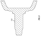
FIG. 3 illustrates a cut-away view of one embodiment of a wheel spindle. -
FIG. 4 illustrates a cut-away side view of one embodiment of a steer-axle high-temperature warning system. -
FIG. 5 illustrates a cut-away side view of another embodiment of a steer-axle high-temperature warning system. -
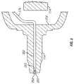
FIG. 6 illustrates a cut-away side view of another embodiment of a steer-axle high-temperature warning system. -
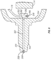
FIG. 7 illustrates a cut-away side view of another embodiment of a steer-axle high-temperature warning system. -
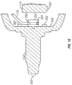
FIG. 8 illustrates a cut-away side view of another embodiment of a steer-axle high-temperature warning system. -
FIG. 9 illustrates a cut-away side view of another embodiment of a steer-axle high-temperature warning system. -
FIG. 10 illustrates a cut-away side view of another embodiment of a steer-axle high-temperature warning system. -
FIG. 11 illustrates a cut-away side view of another embodiment of a steer-axle high-temperature warning system. -
FIG. 12 illustrates a cut-away side view of another embodiment of a steer-axle high-temperature warning system. -
FIG. 13 illustrates a cut-away side view of another embodiment of a steer-axle high-tcmpcraturc warning system. -
FIG. 14 illustrates a cut-away side view of another embodiment of a steer-axle high-temperature warning system. -
FIG. 15 illustrates a cut-away side view of another embodiment of a steer-axle high-temperature warning system. -
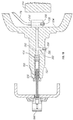
FIG. 16 illustrates a partially exploded view of one embodiment of a steer-axle high-temperature warning system with an automatic tire inflation system. -
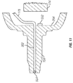
FIG. 17 illustrates a cut-away side view of another embodiment of a steer-axle high-temperature warning system with an automatic tire inflation system. -
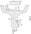
FIG. 18 illustrates a cut-away, side view of another embodiment of a steer-axle high-temperature warning system with an automatic tire inflation system. -
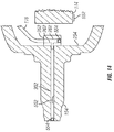
FIG. 19 illustrates a cut-away, side view of another embodiment of a steer-axle high-temperature warning system with an automatic tire inflation system. - As may be seen in
FIG. 1 , avehicle 100 may comprise atruck 102 andtrailer 104. Thetruck 102 may include one ormore drive axles 106 as part of the vehicle's powertrain. Thetruck 102 may further include asteer axle 114 having pivoting hubs that provide steering capability for thevehicle 100. Thetrailer 104 may include one or more fixed axles (not shown). Each axle may have one ormore wheels 108 mounted thereto with atire 110 mounted to eachwheel 108. Of course, other types of steerable vehicles, such as cars and buses may be provided with the high temperature warning system disclosed herein. - The
vehicle 100 may be provided with a pressurized air supply (not shown) used to provide pressurized air to brakes (not shown) and/or to an automatic tire inflation system (indicated with air hoses 112). The steer-axle high-temperature warning system (shown in more detail inFIGS. 4-19 ) may warn a driver when thesteer axle 114 and/or steer axle wheel end reach a predetermined temperature. - Referring now primarily to
FIG. 2 , a vehicle may include a wheel-end high-temperature warning system 150 and asteer axle 114 having awheel spindle 154 on which awheel end assembly 156 may be mounted. Thewheel end assembly 156 may include a hub (not shown) which may rotate oninner bearings 158 andouter bearings 178. Awheel 108, tire 110 (as shown inFIG. 1 ) and hubcap may be mounted to the hub. A brake drum (not shown) may be integrally formed with the hub, or otherwise mounted to the hub. Thewheel end assembly 156 may also include other suitable parts which are not shown but may be monitored by the wheel-end high-temperature warning system 150. - The
outer bearings 178 may be retained on thewheel spindle 154 by aspindle nut 160. Awasher 162 may be mounted between thespindle nut 160 andouter bearing 178. Acotter pin 164 may be inserted through areceiving hole 166 in the end of thewheel spindle 154 so as to prevent thespindle nut 160 from becoming unscrewed from thewheel spindle 154. Thewheel spindle 154 may be pivotally mounted to thefront steer axle 114 via a knuckle post assembly (not shown). - An
oil seal 168 may be mounted to thewheel spindle 154 adjacent theinner bearing 158 so as to prevent loss of lubricant through the inner bearing 158. A hub cap 606 (as shown inFIGS. 16-19 ) may be mounted to the hub, thus generally sealing thebearings - If the
bearings bearings wheel spindle 154, or other wheel end elements may reach in a temperature high enough to ignite thetires 110 and bearing lubricant. Such heat may also be sufficiently high to cause thewheel end assembly 156 to detach from thewheel spindle 154. The disclosed high-temperature warning system may warn the vehicle operator of high temperatures well before the tires ignite or bearings melt, or some other dangerous high-temperature related condition arises in the wheel-end. - The high-
temperature warning system 150 may include anair pressure supply 152, such as that typically provided on atruck 102 orvehicle 100 for various purposes such as air brakes; apressure protection valve 170; aflow switch 172; and an indicator orwarning system light 174. Anair conduit 176 may connect theair pressure supply 152 to one or more normally-closed valves 256 (as shown in the embodiments ofFIGS. 4-19 ). -
FIG. 3 shows a cross section of theexemplary wheel spindle 154 ofFIG. 2 . As may be seen inFIG. 4 , theair conduit 176 may be connected to avalve block 252 mounted to theinner face 254 of thewheel spindle 154. In some embodiments, thevalve block 252 may be comprised of metal or any other suitable thermally-conductive material, and may mounted to thewheel spindle 154, such as by threadable attachment. Thevalve block 252 may be suitably configured so as to allow thevalve block 252 to remain at or near the temperature of thewheel spindle 154 when mounted thereto. A normally-closedvalve 256 may be mounted to thevalve block 252 in fluid communication with theair conduit 176 through achannel 262 which connects theair conduit 176 with the normally-closedvalve 256. - The normally-closed
valve 256 may be opened by a heat sensitive control. In one embodiment, the heat sensitive control may be configured to detect temperature and to open the normally-closedvalve 256 when a predetermined temperature is measured. A pre-determined temperature may be, for example, a temperature well below the softening or melting point of the bearing materials, or well below the tire melting point. The pre-determined temperature may be set well above the maximum temperatures at which a wheel-end assembly may normally operate so as to avoid false alarms. Thus, when the temperature near the hear sensitive control reaches the predetermined temperature, the heat sensitive control will open the normally-closedvalve 256 to allow air to pass through the normally-closedvalve 256. - The heat sensitive control may be any device which is capable of detecting temperature and either directly or indirectly opening a normally-closed valve in response thereto. For example, in some embodiments, the heat sensitive control is
fusible plug 258, a thermallyelectric switch 552, or any other suitable control. The normally-closedvalve 256 and the heat sensitive control may be located at separate locations on thevehicle 100. The heat sensitive control may be mounted in or near the wheel-end assembly in a heat-exchange relationship therewith. In some embodiments the heat sensitive control may be in a conductive heat exchange relationship with the wheel end assembly such that the heat sensitive control detects the approximate temperature of wheel end assembly or specific components thereof, such as the bearings or brakes. For example, the heat sensitive control may be mounted near thewheel end assembly 156 while the normally-closedvalve 256 is mounted at or near theair pressure supply 152. In other embodiments, the heat sensitive control may be mounted near thewheel end assembly 156 while the normally-closedvalve 256 is mounted at another point on or near thewheel end assembly 156, for example as shown inFIGS. 10-15 and19 . In other embodiments, the heat sensitive control may be included within the normally-closedvalve 256 and both the heat sensitive control and the normally-closedvalve 256 may be located at the same position at or near thewheel end assembly 156. For example, in the embodiments ofFIGS. 4-9 and17-18 , the heat sensitive control is contained within the normally-closedvalve 256. InFIGS. 4-9 and 17-18, the heat sensitive control is afusible plug 258 comprising of a eutectic alloy. In one embodiment, thefusible plug 258 is placed within anaperture 260 within the normally-closedvalve 256. Thefusible plug 258 may seal theaperture 260 by being located within theaperture 260, as shown inFIG. 4 . Thefusible plug 258 may open the normally-closedvalve 256 upon a predetermined temperature by melting sharply at the predetermined temperature and thus unsealing theaperture 260 in the normally-closedvalve 256. Thus, thefusible plug 258 may be automatically removed from theaperture 260 when the predetermined temperature is reached, thus opening the normally-closedvalve 256. While any type offusible plug 258 may be satisfactorily used, one sold under the trademark LEEKPRUF sold by the Mueller Refrigeration Company, Inc., is suitable. In some embodiments, when the eutectic alloy of thefusible plug 258 melts, air may escape from theair pressure supply 152 through the normally-closedvalve 256 viaair conduct 176. The escaping air may be detected by theflow switch 172, which may actuate the warning system light 174 showingFig. 1 . The warning system light 174 may be positioned within view of the driver of thevehicle 100 to indicate a problem. In other embodiments, air may escape when the normally-closedvalve 256 is automatically opened, for example, by a thermal electric switch. - As may be seen in the embodiments of
FIGS. 5-19 , one or more normally-closedvalves 256 may be provided in various combinations and at various exemplary locations. Other types of thermally operated, normally-closedvalves 256 and heat sensitive controls may also be used. For example, the heat sensitive control may be a thermalelectric switch 552 which actuates an electrically-operated normally-closedvalve 256 upon a predetermined temperature, as shown inFIGS. 10-15 and19 . The thermalelectric switch 552 may actuate the electrically-operated normally-closedvalve 256 by sending an electric signal via wire or wirelessly to the electrically-operated normally-closedvalve 256 when the thermalelectric switch 552 reaches a predetermined temperature. The electrically-operated normally-closedvalve 256 may then receive the signal and open the normally-closedvalve 256. Thus, in some embodiments, the normally-closedvalve 256 includes the heat sensitive control 57 (as shown inFIGS. 4-9 and16-18 ) while in other embodiments, the heat sensitive control 57 may be located remotely from the normally-closedvalve 256 and may communicate (electronically or otherwise) with and open the normally-closed valve 256 (as shown inFIGS. 10-15 and19 ). - In the embodiment of
FIG. 5 , thewheel spindle 154 may be bored along its central axis to provide anaxial channel 302 in fluid communication with theair conduit 176. A normally-closedvalve 256 containing the heat sensitive control, in this embodiment afusible plug 258 comprising a eutectic alloy, may be threadably mounted in theaxial channel 302 at the outer end of thespindle 154. Theair conduit 176 may be sealingly connected to theaxial channel 302 at theinner face 254 of thespindle 154, or may extend through theaxial channel 302 and sealingly connect to the normally-closedvalve 256. In some embodiments, when thewheel spindle 154 or surroundingwheel end assembly 156 elements reach a predetermined temperature, the eutectic alloy may melt and open theaperture 260 in the normally-closedvalve 256 such that air from theair conduit 176 flows through theaperture 260. A pre-determined temperature may be, for example, a temperature substantially below the temperature at which bearing lubricant burns or bearings melt. - In the embodiment of
FIG. 6 , aradial channel 352 may extend from theaxial channel 302 to an external surface of thespindle 154 so as to allow mounting of a normally-closedvalve 256 adjacent theinner bearings 158 and/or outer bearings 178 (shown inFIG. 2 ). The normally-closedvalve 256 may be sealingly mounted in theradial channel 256 at the external surface of the spindle so as to be in fluid communication with theair conduit 176 such that when the normally-closedvalve 256 is opened, air from theair conduit 176 can escape through the normally-closedvalve 256. As shown in the embodiment ofFIG. 6 , theair conduit 176 may be sealingly connected from theair pressure supply 152 to theinner face 254 of thewheel spindle 154 so as to supply pressurized air to a normally-closedvalve 256 without need for avalve block 252. In some embodiments, theair conduit 176 may be inserted through theaxial channel 302 and/orradial channel 352 to sealingly connect with the normally-closedvalve 256 so as to allow sealed fluid communication from theair pressure supply 152 to the normally-closedvalve 256. - In the embodiment of
FIG. 7 , normally-closedvalves 256 may be located at oneend 303 of theaxial channel 302 and in theradial channel 352. The embodiment ofFIG. 7 may not include avalve block 252 but rather theair conduit 176 may sealingly connect to theaxial channel 302. Of course, theair conduit 176 may also extend through the axial and radial channels for sealing connection directly with the normally-closed valves. In this embodiment, the heatsensitive control 258 may be contained within the normally-closedvalve 256 and may comprise afusible plug 258 made of a cutcctic alloy. - In the embodiment of
FIG. 8 , theair conduit 176 may sealingly connect with thevalve block 252. Normally-closedvalves 256 maybe located at oneend 303 of theaxial channel 302 and invalve block 252. Thevalve block 252 may includechannels 262 which allow theair conduit 176 to fluid communication with theaxial channel 302 and the normally-closedvalves 256. In this embodiment, the heatsensitive control 258 may be contained within the normally-closedvalve 256 and may comprise afusible plug 258 made of a eutectic alloy. - In the embodiment of
FIG. 9 , normally-closedvalves 256 may be mounted in theradial channel 352 in thevalve block 252. In this embodiment, the heatsensitive control 258 may be contained within the normally-closedvalve 256 and may comprise afusible plug 258 made of a eutectic alloy. - In some embodiments, the
air conduit 176 may sealingly connect theair pressure supply 152 to the valve block 252 (as shown inFIG. 9 ) oraxial channel 302 of the wheel spindle 154 (as shown inFIGS. 5-7 ). In some embodiments, theair conduit 176 may run through a hollowfront steer axle 114. In some embodiments, theair conduit 176 may run alongside thefront steer axle 114. In some embodiments, the hollowfront steer axle 114 may be bored or plugged at each end (not shown), and theair conduit 176 may be connected to the hollowfront steer axle 114 so as to use the hollowfront steer axle 114 as part of the air conduit or pressure supply. An air line (not shown) may extend from an axle plug (not shown) to thevalve block 252 orinner face 254 of thewheel spindle 154 to provide fluid communication between theair pressure supply 152 and the normally-closedvalves 256. - Referring now to
FIGS. 10-15 , the heat sensitive control may be a thermalelectric switch 552 which operates an electric-operated normally-closedvalve 554 mounted in avalve block 252 similarly to the valves of previous embodiments. The thermalelectric switch 552 and the electric-operated normally-closedvalve 554 may each include a power source, may receive power from an external power source or may not need a power source. In the embodiment ofFIG. 10 , thermallyelectric switches 552 may be mounted at a variety of locations at or near thewheel end assembly 156. For example, a thermallyelectric switch 552 may be located at the end of thewheel spindle 154. Other thermallyelectric switches 552 may be located on aninner face 254 of thewheel spindle 154. Yet another thermalelectric switch 552 may be located on thesteer axle 114. Each thermalelectric switch 552 may communicate with the normally-closedvalve 256 which may be an electric-operated normally-closedvalve 554. In some embodiments, when any one of the thermallyelectric switches 552 reaches a predetermined temperature, it will send a signal to the electric-operated normally-closedvalve 554 to cause the electric-operated normally-closedvalve 554 to open. In other embodiments, the thermallyelectric switches 552 may communicate with each other or a central processing unit, and may be configured to communicate with the electric-operated normally-closedvalve 554 when a certain number of thermalelectric switches 552 have reached a predetermined temperature. - The embodiment of
FIG. 11 includes one electric-operated normally-closedvalve 554 which is located in theaxial channel 302 and a thermalelectric switch 552 which is located on theinner face 254 of thewheel spindle 154. The embodiment ofFIG. 12 includes one electric-operated normally-closedvalve 554 which is located in theradial channel 352 and one thermalelectric switch 552 which is located on thewheel spindle 154. The embodiment ofFIG. 13 includes two thermallyelectric switches 552 which are located on theinner face 254 of thewheel spindle 154 and one electric-operated normally-closedvalve 554 is located in theaxial channel 302. The embodiment ofFIG. 13 also includes one normally-closedvalve 256 including afusible plug 258 made of a eutectic alloy which is located in theradial channel 352. The embodiment ofFIG. 14 includes two electric-operated normally-closedvalves 554 and two electric-operated normally-closedvalves 554, one which is located in theaxial channel 302 and one which is located on thesteer axle 114. The embodiment ofFIG. 15 includes two thermallyelectric switches 552, one which is located in theradial channel 352 and one which is located in thevalve block 252, and one thermallyelectric switch 552 which is located on thevalve block 252. - Of course, the number and locations of thermal
electric switches 552 in the foregoing embodiment should not be viewed as limiting. Other embodiments may include fewer or additional thermally electric switches and normally-closed valves in a variety of other locations in and about the wheel end assembly. Likewise, thermally-operated normally-closed valves may be used in combination with fusible plug normally-closed valves. Thevalve block 252 may be of any suitable configuration adapted for mounting to the wheel spindle, whether at theinner face 254 or elsewhere. Thevalve block 252 may be further provided with one ormore channels 262 to allow fluid communication fromair conduit 176 to one or more normally-closed valves. Furthermore, theradial channel 352 may extend from theaxial channel 302 at any point along theaxial channel 302. A wheel spindle may have formed therein more than oneaxial channel 302 and may have formed therein more than oneradial channel 352. - The high temperature warning system may provide a stand-alone system for vehicles, or the warning system may be easily adapted for use with an automatic tire inflation system which may also use the
air pressure supply 152 and a warning system light 174 shown inFig. 1 . The high temperature warning system may be used with various types of automatic tire inflation systems, one type of which is shown in the embodiments ofFIGS. 16-19 and more fully described and illustrated inU.S. Patent No. 6,698,482 , entitled "Rotary Air Connection With Bearing For Tire Inflation System," which is hereby incorporated by reference. As shown inFIG. 1 , the automatic tire inflation system may be used to control air pressure in one or more of thetires 110 mounted to steeraxle 114,drive axle 106 and trailer axles (not shown). The automatic tire inflation system may include one ormore air hoses 112 in fluid communication with eachtire 110. Other automatic tire inflation systems, such as without limitation those disclosed inU.S. Pat. No. 7,273,082 ,6,325,124 , and6,105,645 , andU.S. Pub. App. No. 2009/0283190 . - Now referring to
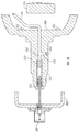
FIGS. 16-17 , arotary union 652 may be provided for supplying air from anair pressure supply 152 in an automatic tire inflation system throughair hoses 604 to the rotating tires (not shown) mounted towheels 108. Ahub cap 606 may be provided at each end of thewheel spindle 154 for retaining lubricant in the wheel bearings (not shown). Anair conduit 176 may supply air to therotary union 652 through anaxial channel 302 in thewheel spindle 154. Therotary union 652 may be supported and positioned in the center end of thewheel spindle 154, and may sealingly engage the interior of thewheel spindle 154 if air is injected directly into theaxial channel 302 of thewheel spindle 154. - As shown more particularly in
FIG. 17 , therotary union 652 may have a firststationary part 654 or stator having apassageway 656 therethrough. The firststationary part 654 may include afilter 674 to remove debris that may be carried through theaxial channel 302. Thepassageway 656 may be in fluid communication with theair pressure supply 152 throughair conduit 176 and, in some embodiments, avalve block 252. Afirst rotary seal 658 may be supported in and encircle thepassageway 656. Therotary union 652 may include a rotatable part including atubular member 660 having afirst end 662 and asecond end 664. Thesecond end 664 of thetubular member 660 may be coaxially extendable through and longitudinally and rotationally movable in thepassageway 656, and may sealably engage the firstrotary seal 658 and so as to allow sealed fluid communication with theair pressure supply 152. Thefirst end 662 of thetubular member 660 may be rotatably and sealably connected through a secondrotary seal 668 to anair connection 666 or tee-body mounted on thehub cap 606. Theair connection 666 may be provided on thehub cap 606 for communicating air to the tire or tires 110 (seen inFIG. 1 ) via an air hose 604 (seen inFIG. 16 ) connected to the wheel valves 602 (seen inFIG. 16 ). Thefirst end 662 of thetubular member 660 may include ashoulder 670 that co-acts with abearing 672. In operation, air may be supplied through the stationary part of therotary union 652. Thehub cap 606 andair connection 666 may rotate with thewheels 108 relative to thewheel spindle 154. Air may flow from thepressure supply 152 through thefilter 674 into thestationary part 654 of therotary union 652. Air may flow from thestationary part 654 through thetubular member 660 to the tee-body 666. Air may flow from the tee-body 666 throughair hoses 604 andtire valves 602 into the tires. Of course, if the automatic tire inflation system provides for tire deflation, air may flow in the reverse direction as that just described. - Thus, the automatic tire inflation system of
FIGS. 16-19 may include anair pressure supply 152 and a suitable warning system comprising aflow switch 172 and a warning system light 174, all of which may be used as part of a high temperature warning system as disclosed herein. The use of a normally-closedvalve 256 at a location near thewheel bearings wheel spindle 154 may provide a high temperature warning system. Again, if thewheel spindle 154 reaches a predetermined temperature, the normally-closedvalve 256 will open, such as by the melting of afusible plug 258 in some embodiments, releasing air from theair pressure supply 152 and actuating the warning system light 174 for notification of the operator. Of course, a warning buzzer or audible alarm may be used in place of the light 174. The operator may quickly determine whether the warning system light 174 indicates a pressure leak in thetires 110 or a high temperature problem in the wheel hub area. In some embodiments, air escaping through a channel formed in thevalve 256 may provide an audible warning of high temperature conditions. Thevalve 256 configuration may thus serve as a warning indicator. Thus, awarning light 174 need not be used, or may be used in conjunction with human-audible or ultrasonic warning indicators. - Referring now to the embodiment of
FIG. 18 , shown including an automatic tire inflation system, additional normally-closedvalves 256 may be provided such as in theradial channel 352. The normally-closedvalve 256 may be connected to theair pressure supply 152 through theair conduit 176. - Referring now to
FIG. 19 , another embodiment is shown, which includes an automatic tire inflation system, and further includes one electric-operated normally-closedvalve 554 which, in this embodiment, is operable by two thermallyelectric switches 552 on theinner face 254 of thewheel spindle 154. The electric-operated normally-closedvalve 554 may be located in aradial channel 352 so as to be adjacent theinner bearings 158 and/orouter bearings 178. Of course, the thermally electric switches may be placed at other suitable locations, such as onhubcap 606 or onstator 654. - Thus, a high-temperature warning system may be readily used in connection with an automatic tire inflation system in a similar manner and configuration as it would be used without an automatic tire inflation system. Any of the embodiments disclosed herein may be equally suitable for implementation as standalone systems or in connection with an automatic tire inflation system.
- Although the present invention and its advantages have been described in detail, it should be understood that various changes, substitutions and alterations can be made herein without departing from the invention as defined by the appended claims. Moreover, the scope of the present application is not intended to be limited to the particular embodiments of the process, machine, manufacture, composition, or matter, means, methods and steps described in the specification. As one will readily appreciate from the disclosure, processes, machines, manufacture, compositions of matter, means, methods, or steps, presently existing or later to be developed that perform substantially the same function or achieve substantially the same result as the corresponding embodiments described herein may be utilized. Accordingly, the appended claims are intended to include within their scope such processes, machines, manufacture, compositions of matter, means, methods or steps.
- The claims of the parent application are reproduced below on pages 15-18. These clauses define preferred embodiments. The applicant reserves the right to pursue protection for the combinations of features set out in these clauses, and/or for any other subject-matter contained in the parent application as filed, either in the present divisional application or in a further application divided from the present divisional application. The claims of the parent application are not the claims of this divisional application.
-
- 1. A high temperature warning system for a steer-axle wheel end assembly, the system comprising:
- an air pressure supply,
- a normally-closed valve in sealed fluid communication with the air pressure supply,
- a heat sensitive control capable of opening the normally-closed valve upon a predetermined temperature, the heat sensitive control mounted on or near the steer-axle wheel end assembly in a heat exchange relationship therewith, and
- a warning indicator connected to the air pressure supply for actuation upon opening of the normally-closed valve.
- 2. The system of clause 1 wherein the heat sensitive control forms part of the normally-closed valve.
- 3. The system of clause 2 wherein the normally-closed valve comprises a fusible plug and the heat sensitive control comprises a eutectic alloy capable of melting and opening the normally-closed valve upon a predetermined temperature.
- 4. The system of clause 3, the steer-axle wheel end assembly comprising a spindle having an inner face, the system further comprising a valve block mounted to the inner face of the spindle in a heat exchange relationship therewith, the normally-closed valve mounted to the valve block, and the air pressure supply sealingly connected to the valve block in fluid communication with the normally-closed valve.
- 5. The system of clause 3, the steer-axle wheel end assembly comprising a spindle having a channel formed therein extending approximately along the central axis of the spindle about which a wheel may rotate, the channel extending from an inner face of the spindle to an outer end of the spindle, and the normally-closed valve is sealingly mounted in the channel at the outer end of the spindle and the air pressure supply is in sealed fluid communication with the normally-closed valve through the channel.
- 6. The system of clause 3, the steer-axle wheel end assembly comprising a spindle having a first channel formed therein extending approximately along the central axis of the spindle about which a wheel may rotate, and a second channel formed therein extending approximately radially from the first channel to an external surface of the spindle, and the normally-closed valve is sealingly mounted in the second channel at the external surface of the spindle and the air pressure supply is in sealed fluid communication with the normally-closed valve through the first channel and second channel.
- 7. The system of clause 1, wherein the warning indicator comprises a flow switch capable of sensing air flow from the air pressure supply, and a warning light capable of activation by the flow switch.
- 8. The system of clause 3, wherein the warning indicator comprises a channel formed in the normally-closed valve through which air may flow and produce sound audible to humans when the normally-closed valve opens.
- 9. An automatic tire inflation and high-temperature warning system for a steer-axle wheel end assembly comprising a spindle, bearings mounted to the spindle, a hub rotatably mounted to the bearings, a wheel mounted to the hub, and a pneumatic tire mounted to the wheel, the system comprising:
- an air pressure supply,
- a rotary union mounted to the spindle and in sealed communication with the air pressure supply and with the tire,
- a normally-closed valve in sealed fluid communication with the air pressure supply,
- a heat sensitive control capable of opening the normally-closed valve upon a predetermined temperature, the heat sensitive control mounted on or near the steer-axle wheel end assembly in a heat exchange relationship therewith, and
- a warning indicator connected to the air pressure supply for actuation upon opening of the normally-closed valve.
- 10. The system of clause 9, the spindle having a channel formed therein extending approximately along the central axis of the spindle about which a wheel may rotate, the channel extending from an inner face of the spindle to an outer end of the spindle, wherein the rotary union is sealingly mounted in the channel at the outer end of the spindle, and the air pressure supply is in sealed fluid communication with the rotary union through the channel.
- 11. The system of clause 10, the system further comprising a valve block sealingly mounted the inner face of the spindle in a heat exchange relationship therewith and in fluid communication with the channel, the normally-closed valve mounted to the valve block, and the air pressure supply sealingly connected to the valve block in fluid communication with the normally-closed valve and channel.
- 12. A high temperature warning system for a steer-axle wheel end assembly, the system comprising:
- a normally-closed valve capable of sealed fluid communication with an air pressure supply,
- a heat sensitive control, mountable on or near the steer-axle wheel end assembly in a heat exchange relationship therewith, and capable of connecting to the normally-closed valve and opening the normally-closed valve upon a predetermined temperature, and
- a warning indicator connected to the air pressure supply for actuation upon opening of the normally-closed valve.
- 13. A high temperature warning system for a steer-axle wheel end assembly, the system comprising:
- an air pressure supply,
- a electrically-operated normally-closed valve in sealed fluid communication with the air pressure supply,
- a thermal electric switch capable of opening the normally-closed valve upon a predetermined temperature, the thermal electric switch mounted on or near the steer-axle wheel end assembly in a heat exchange relationship therewith, and
- a warning indicator connected to the air pressure supply for actuation upon opening of the electrically-operated normally-closed valve.
Claims (15)
- A high temperature warning system for a steer-axle wheel end assembly, the system comprising a steer-axle spindle (154) having an inner face (254) and a free end, a pressurized fluid supply (152), a first normally-closed valve (256, 554), a first heat sensitive control (258, 552) capable of opening the first normally-closed valve (256, 554) at a predetermined temperature and a warning indicator (174) connected to the pressurized fluid supply (152) and actuatable upon opening of the first normally-closed valve (256, 554),
the first normally-closed valve (256, 554) in sealed fluid communication with the pressurized fluid supply (152),
the first heat sensitive control (258, 552) mounted to or near the steer-axle wheel end assembly in a heat exchange relationship therewith. - The system of claim 1 wherein the first heat sensitive control (258, 552) is mounted:to the steer-axle spindle (154); orto the inner face (254) of the steer-axle spindle (154); orto the free end of the steer-axle spindle (154); ornear the steer-axle spindle (154).
- The system of claim 1, further comprising:a valve block (252) mounted to the inner face (254) of the spindle in a heat exchange relationship therewith, andthe first normally-closed valve (256, 554) mounted to the valve block, and the pressurized fluid supply (152) sealingly connected to the valve block in fluid communication with the normally-closed valve (256, 554).
- The system of claim 3, further comprising:the steer-axle spindle forming a channel (302) along the central axis of the steer-axle spindle (154) and in sealed fluid communication with the pressurized fluid supply (152) at the inner face (254), anda second normally-closed valve (256, 554) mounted to the steer-axle spindle (154) in sealed fluid communication with the pressurized fluid supply (152) through the channel (302).
- The system of claim 4, wherein the channel (302) extends from the inner face (254) to:the free end of the steer-axle spindle (154), the second normally-closed valve (256, 554) being sealingly mounted to the channel at or near the free end of the steer-axle spindle (154); oran external surface of the steer-axle spindle (154), the second normally-closed valve (256, 554) being sealingly mounted to the channel at the external surface of the steer-axle spindle (154).
- The system of claim 4, further comprising a second heat sensitive control (258, 552) capable of opening the second normally-closed valve (256, 554) at a predetermined temperature.
- The system of claim 6, wherein the first heat sensitive control (258) forms part of the first normally-closed valve (256, 554) and the second heat sensitive control (258) forms part of the second normally-closed valve (256, 554), optionally wherein the first heat sensitive control (258) comprises a eutectic alloy capable of melting and opening the first normally-closed valve (256, 554) upon reaching the predetermined temperature, and the second heat sensitive control (258) comprises a eutectic alloy capable of melting and opening the second normally-closed valve (256, 554) upon reaching the predetermined temperature.
- The system of claim 3, further comprising:the steer-axle spindle forming a channel (302) along the central axis of the steer-axle spindle (154) and extending from the inner face (254) to the free end of the steer-axle spindle (154), the channel (302) being in sealed fluid communication with the pressurized fluid supply (152) at the inner face (254), anda rotary union (652) sealingly mounted to the channel at the outer end of the steer-axle spindle (154), the rotary union (652) being in sealed communication with the pressurized fluid supply (152) and with a tire.
- The system of claim 8, wherein the channel (302) also extends from the inner face (254) to an external surface of the steer-axle spindle (154), the system further comprising a second normally-closed valve (256, 554) mounted to the steer-axle spindle (154) in sealed fluid communication with the pressurized fluid supply (152) through the channel (302), optionally wherein the first heat-sensitive control (258, 552) is mounted to the inner face (254) of the steer-axle spindle (154) or to the valve block (252).
- The system of claim 8, wherein the channel (302) also extends from the inner face (254) to an external surface of the steer-axle spindle (154), the system further comprising a second normally-closed valve (256, 554) mounted to the steer-axle spindle (154) in sealed fluid communication with the pressurized fluid supply (152) through the channel (302) and the system further comprises a second heat sensitive control (258, 552) capable of opening the second normally-closed valve (256, 554) at a predetermined temperature, optionally wherein the second heat-sensitive control (258, 552) is mounted to the inner face (254) of the steer-axle spindle (154) or to the valve block (252).
- The system of claim 8,
wherein the channel (302) also extends from the inner face (254) to an external surface of the steer-axle spindle (154), the system further comprising a second normally-closed valve (256, 554) mounted to the steer-axle spindle (154) in sealed fluid communication with the pressurized fluid supply (152) through the channel (302) and the system further comprises a second heat sensitive control (258, 552) capable of opening the second normally-closed valve (256, 554) at a predetermined temperature;
wherein the first heat sensitive control (258) forms part of the first normally-closed valve (256, 554) and the second heat sensitive control (258) forms part of the second normally-closed valve (256, 554); and
optionally, wherein the first heat sensitive control (258) comprises a eutectic alloy capable of melting and opening the first normally-closed valve (256, 554) upon reaching the predetermined temperature, and the second heat sensitive control (258) comprises a eutectic alloy capable of melting and opening the second normally-closed valve (256, 554) upon reaching the predetermined temperature. - The system of claim 1, further comprising:the steer-axle spindle forming a channel (302) along the central axis of the steer-axle spindle (154) and in sealed fluid communication with the pressurized fluid supply (152) at the inner face (254), andthe first normally-closed valve (256, 554) mounted to the steer-axle spindle (154) in sealed fluid communication with the pressurized fluid supply (152) through the channel (302).
- The system of claim 12, wherein the channel (302) extends from the inner face (254) to:the free end of the steer-axle spindle (154), the first normally-closed valve (256, 554) being sealingly mounted to the channel at or near the free end of the steer-axle spindle (154); oran external surface of the steer-axle spindle (154), the first normally-closed valve (256, 554) being sealingly mounted to the channel at or near the external surface of the steer-axle spindle (154).
- The system of claim 12, wherein the first heat-sensitive control (552):is mounted to the inner face (254) of the steer-axle spindle (154); oris disposed in the channel (302);is mounted to an external surface of the steer-axle spindle (154); orforms part of the first normally-closed valve (256, 554) and comprises a eutectic alloy capable of melting and opening the first normally-closed valve (256, 554) upon reaching the predetermined temperature.
- The system of claim 12,
wherein the channel (302) extends from the inner face (254) to the free end of the steer-axle spindle (154), the channel (302) being in sealed fluid communication with the pressurized fluid supply (152) at the inner face (254), and
wherein the channel (302) also extends from the inner face (254) to an external surface of the steer-axle spindle (154), the system further comprising a second normally-closed valve (256, 554) mounted to the steer-axle spindle (154) in sealed fluid communication with the pressurized fluid supply (152) through the channel (302), and
the system further comprising a rotary union (652) sealingly mounted to the channel at outer end of the steer-axle spindle (154), the rotary union (652) being in sealed communication with the pressurized fluid supply (152) and with a tire.
Applications Claiming Priority (2)
| Application Number | Priority Date | Filing Date | Title |
|---|---|---|---|
| US36896010P | 2010-07-29 | 2010-07-29 | |
| EP11812972.5A EP2598346B1 (en) | 2010-07-29 | 2011-07-21 | Steer axle high-temperature warning system |
Related Parent Applications (2)
| Application Number | Title | Priority Date | Filing Date |
|---|---|---|---|
| EP11812972.5A Division EP2598346B1 (en) | 2010-07-29 | 2011-07-21 | Steer axle high-temperature warning system |
| EP11812972.5A Division-Into EP2598346B1 (en) | 2010-07-29 | 2011-07-21 | Steer axle high-temperature warning system |
Publications (1)
| Publication Number | Publication Date |
|---|---|
| EP3028879A1 true EP3028879A1 (en) | 2016-06-08 |
Family
ID=45530454
Family Applications (2)
| Application Number | Title | Priority Date | Filing Date |
|---|---|---|---|
| EP16151339.5A Withdrawn EP3028879A1 (en) | 2010-07-29 | 2011-07-21 | Steer axle high-temperature warning system |
| EP11812972.5A Not-in-force EP2598346B1 (en) | 2010-07-29 | 2011-07-21 | Steer axle high-temperature warning system |
Family Applications After (1)
| Application Number | Title | Priority Date | Filing Date |
|---|---|---|---|
| EP11812972.5A Not-in-force EP2598346B1 (en) | 2010-07-29 | 2011-07-21 | Steer axle high-temperature warning system |
Country Status (10)
| Country | Link |
|---|---|
| US (5) | US8910683B2 (en) |
| EP (2) | EP3028879A1 (en) |
| CN (2) | CN103209842B (en) |
| BR (1) | BR112013002198A2 (en) |
| CA (1) | CA2805280C (en) |
| ES (1) | ES2582043T3 (en) |
| HK (2) | HK1180284A1 (en) |
| MX (3) | MX2013001164A (en) |
| WO (1) | WO2012015669A1 (en) |
| ZA (1) | ZA201300197B (en) |
Families Citing this family (17)
| Publication number | Priority date | Publication date | Assignee | Title |
|---|---|---|---|---|
| BR112012033114B1 (en) * | 2010-06-21 | 2021-02-09 | Equalaire Systems, Inc | swiveling air connection with central valve for tire inflation system |
| MX2013001164A (en) | 2010-07-29 | 2013-02-27 | Equalaire Systems Inc | Steer axle high-temperature warning system. |
| US9248705B2 (en) * | 2010-10-04 | 2016-02-02 | Agco International Gmbh | Rotary joint |
| CN102645938A (en) * | 2012-04-01 | 2012-08-22 | 上海大学 | Real-time temperature control system of automobile brake block |
| DE102014218328B4 (en) * | 2014-09-12 | 2019-03-28 | Saf-Holland Gmbh | transaxle |
| DE102014218325B4 (en) | 2014-09-12 | 2021-10-28 | Saf-Holland Gmbh | Axle unit |
| DE102014218331B4 (en) * | 2014-09-12 | 2018-11-08 | Saf-Holland Gmbh | transaxle |
| DE102014218332B4 (en) | 2014-09-12 | 2022-05-05 | Saf-Holland Gmbh | axle unit |
| EP3265329B1 (en) * | 2015-03-05 | 2021-11-17 | Equalaire Systems, Inc. | Steer axle tire inflation system |
| ITUB20155836A1 (en) * | 2015-11-24 | 2017-05-24 | Fiat Ricerche | Centralized on-board system for adjusting the tire pressure of a vehicle |
| BR112021000904A2 (en) * | 2018-07-31 | 2021-04-13 | Equalaire Systems, Inc. | DIGITAL WHEEL AXLE TIP ASSEMBLY TEMPERATURE MONITORING SYSTEM |
| DE102018122413B3 (en) * | 2018-09-13 | 2019-08-14 | Gigant - Trenkamp & Gehle Gmbh | Tire pressure control system with compressed air supply by means of a compressed air line formed inside a rigid axle body |
| DE102019205003A1 (en) * | 2019-04-08 | 2020-10-08 | Zf Friedrichshafen Ag | Melt valve for a line system to effect a protective function of a component |
| US11179976B2 (en) | 2019-05-14 | 2021-11-23 | Cnh Industrial America Llc | Work vehicle with partially rotatable tire inflation pack |
| US11376898B1 (en) | 2021-07-19 | 2022-07-05 | Globetech Manufacturing, Inc. | Air inflation system |
| CN113479135A (en) * | 2021-08-06 | 2021-10-08 | 安徽佳乐建设机械有限公司 | Axle high temperature early warning system |
| DE102022114807A1 (en) | 2022-06-13 | 2023-12-14 | Saf-Holland Gmbh | Compressed air transmission system, tire inflation system, axle unit and a commercial vehicle |
Citations (8)
| Publication number | Priority date | Publication date | Assignee | Title |
|---|---|---|---|---|
| US6105645A (en) | 1998-05-14 | 2000-08-22 | Ingram; Anthony L. | Rotary union assembly for use in air pressure inflation systems for tractor trailer tires |
| US6325124B1 (en) | 2000-02-03 | 2001-12-04 | Col-Ven S.A. | Pneumatic rotary wheel coupling |
| US6698482B2 (en) | 2002-07-01 | 2004-03-02 | Equalaire Systems, Inc. | Rotary air connection with bearing for tire inflation system |
| US7273082B2 (en) | 2004-03-05 | 2007-09-25 | Hendrickson Usa, L.L.C. | Tire inflation system apparatus and method |
| US7302979B2 (en) * | 2005-03-16 | 2007-12-04 | Dana Corporation | Vehicle tire inflation system and sensor and method of use |
| US7416005B2 (en) * | 2003-09-09 | 2008-08-26 | Equalaire Sytstems, Inc. | Wheel end assembly high-temperature warning system |
| US20090283190A1 (en) | 2008-05-16 | 2009-11-19 | Hendrickson Usa, L.L.C. | Integrated rotary union and hub cap |
| US20090284362A1 (en) * | 2008-05-16 | 2009-11-19 | Hendrickson Usa, L.L.C. | Vehicle temperature warning system |
Family Cites Families (81)
| Publication number | Priority date | Publication date | Assignee | Title |
|---|---|---|---|---|
| US1072907A (en) | 1911-07-26 | 1913-09-09 | Lester L Brooks | Automobile tire-inflating mechanism. |
| US1054504A (en) | 1911-09-07 | 1913-02-25 | Louis Burgraff Jr | Means for tire inflation. |
| US1083847A (en) | 1912-09-19 | 1914-01-06 | Charles P Mcdowell | System for inflating pneumatic tires. |
| US1112596A (en) | 1913-05-28 | 1914-10-06 | Louis Burggraf Jr | Means for tire inflation. |
| US1205504A (en) | 1915-06-11 | 1916-11-21 | Rees J Jones | Fluid-tight swivel-joint. |
| US1165057A (en) | 1915-07-03 | 1915-12-21 | Donald Alvord | Tire-inflating device. |
| GB344109A (en) | 1929-12-23 | 1931-03-05 | Richard Hurtley Daneel | Improvements in means for transmitting fluid pressure from a stationary to a rotary part, more particularly for inflating pneumatic tyres |
| US2107405A (en) | 1934-01-25 | 1938-02-08 | Schraders Son Inc | Rotating joint for running inflation |
| US2177042A (en) | 1934-12-19 | 1939-10-24 | Michael Paul | Tire tread and pressure regulating device |
| US2693841A (en) | 1951-03-07 | 1954-11-09 | Mack Mfg Corp | Tire inflation and deflation system |
| US2685906A (en) | 1952-01-19 | 1954-08-10 | Scovill Manufacturing Co | Running inflation and deflation system |
| US2854018A (en) | 1954-10-05 | 1958-09-30 | Scovill Manufacturing Co | Quick-dump extension for airplane tire valve |
| US2947172A (en) | 1954-11-17 | 1960-08-02 | Gen Motors Corp | Balancing organization |
| US3276503A (en) | 1965-01-21 | 1966-10-04 | Scovill Manufacturing Co | Tire pressure maintenance system |
| US3645479A (en) | 1970-03-16 | 1972-02-29 | Boeing Co | Aircraft tire explosion prevention system |
| GB1428632A (en) | 1973-02-20 | 1976-03-17 | Nissan Motor | Tyre air pressure sensor |
| US3898638A (en) | 1973-08-09 | 1975-08-05 | Robert A Deane | Differential temperature sensor system and improvements in a fluid flow detector |
| US4004271A (en) | 1974-12-13 | 1977-01-18 | General Motors Corporation | Low tire pressure warning system |
| US4058185A (en) | 1976-08-09 | 1977-11-15 | Ploeger Kenneth C | Automatic wheel bearing lubricator |
| US4333304A (en) | 1981-03-26 | 1982-06-08 | Sperry Corporation | Adjustable crop guide apparatus |
| US4387931A (en) | 1981-04-13 | 1983-06-14 | The Budd Company | Tire pressure control in a vehicle |
| US4492019A (en) | 1983-06-30 | 1985-01-08 | Rockwell International Corporation | Method of forming an axle |
| US4700763A (en) | 1984-03-29 | 1987-10-20 | The United States Of America As Represented By The Secretary Of The Air Force | Remotely controlled aircraft tire inflation/deflation valve |
| US4685501A (en) | 1986-03-06 | 1987-08-11 | Williams Donald E | Remotely controlled inflation/deflation valve system for a vehicle tire |
| US4812826A (en) | 1987-03-26 | 1989-03-14 | Carnegie-Mellon University | Thermal sensor for detection of railroad bearing failures |
| US4883106A (en) | 1989-01-19 | 1989-11-28 | Eaton Corporation | Rotary wheel-end assembly for tire inflation system |
| US4947786A (en) | 1989-05-15 | 1990-08-14 | Maynard Raymond L | Overheated-axle indicator device |
| DE69115557T2 (en) | 1990-05-17 | 1996-06-05 | Equalaire Systems Inc | Air control system for vehicle tires |
| US5293919A (en) | 1991-11-18 | 1994-03-15 | Hughes Aircraft Company | Self-regulating tire pressure system and method |
| US5200697B1 (en) | 1991-11-27 | 1996-06-18 | Ntn Toyo Bearing Co Ltd | Hub and bearing assembly with integrated rotation sensor including a tone ring and annular transducer |
| US5309969A (en) | 1991-12-17 | 1994-05-10 | Chander Mittal | Apparatus for repeatable adjustment of tire pressure |
| US5587698A (en) | 1992-02-05 | 1996-12-24 | Genna; Robert A. | Automatic tire pressure control system for a vehicle |
| US5429167A (en) | 1993-08-13 | 1995-07-04 | Oshkosh Truck Corporation | Universal central tire inflation system for trailers |
| US5377736A (en) | 1993-11-18 | 1995-01-03 | Marks-Rms, Inc. | Driven axle vehicle inflation system |
| US5584949A (en) | 1994-05-06 | 1996-12-17 | Ingram; Anthony L. | Air inflation system for trailer axles |
| US5538062A (en) | 1994-08-12 | 1996-07-23 | Marks-Rms, Inc. | Pnuematic tire inflation system |
| US5492393A (en) | 1994-09-15 | 1996-02-20 | Skf Usa Inc. | Hub cap vent device |
| US5553647A (en) | 1994-12-14 | 1996-09-10 | Hayes Wheels International, Inc. | Central tire inflation system |
| US5584773A (en) | 1995-07-12 | 1996-12-17 | Caterpillar Inc. | Fluid circulatory system for an axle assembly |
| DE19543612C1 (en) | 1995-11-23 | 1997-05-07 | Glyco Antriebstechnik Gmbh | Clamping device with integrated fluid rotating union |
| US5565065A (en) | 1995-11-28 | 1996-10-15 | Wang; Chin-Tu | Distilled water supply device |
| US5694969A (en) | 1996-01-22 | 1997-12-09 | Devuyst; Christopher | Pressure relief tire valve |
| US5769979A (en) | 1996-08-30 | 1998-06-23 | Equalaire Systems, Inc. | Rotary air connection for tire inflation system |
| US5868881A (en) | 1996-09-04 | 1999-02-09 | Equalaire Systems, Inc. | Rotary air coupling for tire inflation system |
| CA2199649A1 (en) * | 1997-03-11 | 1998-09-11 | Ken Adams | Wheel monitoring device |
| FR2761652B1 (en) | 1997-04-07 | 1999-06-04 | Zefal | INFLATION DEVICE USING A BOTTLE OR CARTRIDGE OF COMPRESSED GAS |
| US6938658B2 (en) | 2003-06-09 | 2005-09-06 | Airgo Ip, Llc | Expandable spindle plug assembly for use with automatic tire inflation systems |
| US6167900B1 (en) | 1999-02-12 | 2001-01-02 | David Norman Laird | Valve stem with slidable, rotatable air-tight coupling for removably attachable devices |
| US6394556B1 (en) | 1999-03-15 | 2002-05-28 | Anthony L. Ingram | Press-expansion plug filter assembly for use with air pressure inflation systems for tractor trailer tires |
| US6131631A (en) | 1999-05-10 | 2000-10-17 | Equalaire Systems, Inc. | Press plug support for tire inflation system |
| WO2001002196A1 (en) | 1999-07-02 | 2001-01-11 | Pressure Guard, Inc. | On-axle tire inflation system |
| US6244316B1 (en) * | 1999-07-16 | 2001-06-12 | Vehicle Inflation Technologies, Inc | Vehicle tire inflation system |
| US6401743B1 (en) | 1999-08-25 | 2002-06-11 | Vehicle Inflation Technologies | Automatic tire inflation system having a pressure regulator with an integrated leak detection switch |
| US6145559A (en) | 1999-09-03 | 2000-11-14 | Accessio, Ltd. | Axle and hub assembly for automatic tire inflation pressurization system |
| US6283186B1 (en) | 1999-11-23 | 2001-09-04 | Dana Corporation | Tire inflation system for live spindle wheel end |
| US6325123B1 (en) | 1999-12-23 | 2001-12-04 | Dana Corporation | Tire inflation system for a steering knuckle wheel end |
| US6670890B2 (en) | 2000-02-03 | 2003-12-30 | Meritor Heavy Vehicle Technology Llc | Thermally activated sensor system |
| US6435238B1 (en) | 2001-03-22 | 2002-08-20 | Equalaire Systems, Inc. | Combination of an automatic tire inflation system and anti-locking braking system |
| US6759963B2 (en) | 2001-05-08 | 2004-07-06 | Meritor Heavy Vehicle Technology, Llc | Wheel bearing temperature indicator |
| US6546892B2 (en) | 2001-06-07 | 2003-04-15 | Walter P. Kelly, Jr. | Overheating axle warning device |
| US6571818B2 (en) | 2001-06-19 | 2003-06-03 | Peach/Wheeler Associates, Llc | Damage resistant break away valve stem |
| US6668888B1 (en) | 2002-07-19 | 2003-12-30 | Torque-Traction Technologies, Inc. | Central tire inflation system for steering drive axle |
| US7207365B2 (en) * | 2003-03-06 | 2007-04-24 | Nelson Christopher A | Central tire inflation system rotary air union |
| BRPI0405231B1 (en) | 2003-03-06 | 2013-02-19 | Tire inflation method and system. | |
| US6772812B1 (en) | 2003-03-25 | 2004-08-10 | Autoliv Asp, Inc. | Dual-function tire inlet valve |
| US7191796B1 (en) | 2003-08-15 | 2007-03-20 | Rehmert Jr Paul E | Dual outlet air valve |
| US7306020B2 (en) * | 2005-04-19 | 2007-12-11 | Dana Corporation | Tire inflation system and wheel sensor and method of use |
| US7652562B2 (en) | 2005-10-13 | 2010-01-26 | Hendrickson Usa, L.L.C. | Vehicle temperature warning system and method |
| WO2008042994A2 (en) | 2006-10-03 | 2008-04-10 | John Kostin Milanovich | Inflation stem with blow-off valve to prevent overinflation |
| US7896045B2 (en) | 2006-11-13 | 2011-03-01 | The Board Of Regents For Oklahoma State University | Apparatus for delivering air through powered axle assemblies |
| DE102007005765A1 (en) | 2007-02-06 | 2008-08-14 | Fereshteh Saadat | Wheel axle and drive or propeller shaft |
| US20090084481A1 (en) | 2007-10-01 | 2009-04-02 | Kalavitz Michael V | Tire inflation control method and apparatus |
| FR2922484B1 (en) | 2007-10-23 | 2016-06-03 | Messier Bugatti | DEVICE FOR CONNECTING AN AIRCRAFT WHEEL TIRE TO A PNEUMATIC AIRCRAFT CONTROL PANEL |
| US7690412B1 (en) | 2008-11-04 | 2010-04-06 | Arvinmeritor Technology, Llc | Drive axle with air passage for tire inflation system |
| BR112012033114B1 (en) | 2010-06-21 | 2021-02-09 | Equalaire Systems, Inc | swiveling air connection with central valve for tire inflation system |
| MX2013001164A (en) | 2010-07-29 | 2013-02-27 | Equalaire Systems Inc | Steer axle high-temperature warning system. |
| US20120032793A1 (en) * | 2010-07-30 | 2012-02-09 | Frank Joseph Sonzala | Visual wheel end assembly high-temperature warning system |
| MX2012014030A (en) | 2010-07-30 | 2013-02-12 | Hendrickson Usa Llc | Constant pressure pneumatic balancing tire inflation system. |
| GB201021928D0 (en) | 2010-12-23 | 2011-02-02 | Agco Internat Ltd | Tyre inflation |
| CN103596780B (en) * | 2011-06-07 | 2016-06-08 | 伊夸莱尔系统公司 | Use the system and method for air relief valve |
| WO2014150410A2 (en) | 2013-03-15 | 2014-09-25 | Dana Heavy Vehicle Systems Group, Llc | Assembly |
-
2011
- 2011-07-21 MX MX2013001164A patent/MX2013001164A/en active IP Right Grant
- 2011-07-21 EP EP16151339.5A patent/EP3028879A1/en not_active Withdrawn
- 2011-07-21 EP EP11812972.5A patent/EP2598346B1/en not_active Not-in-force
- 2011-07-21 MX MX2017007544A patent/MX358126B/en unknown
- 2011-07-21 MX MX2015014819A patent/MX349102B/en unknown
- 2011-07-21 CA CA2805280A patent/CA2805280C/en not_active Expired - Fee Related
- 2011-07-21 CN CN201180037092.5A patent/CN103209842B/en not_active Expired - Fee Related
- 2011-07-21 ES ES11812972.5T patent/ES2582043T3/en active Active
- 2011-07-21 BR BR112013002198A patent/BR112013002198A2/en active Search and Examination
- 2011-07-21 US US13/808,940 patent/US8910683B2/en not_active Expired - Fee Related
- 2011-07-21 CN CN201610232797.7A patent/CN105835635B/en not_active Expired - Fee Related
- 2011-07-21 WO PCT/US2011/044879 patent/WO2012015669A1/en active Application Filing
-
2013
- 2013-01-08 ZA ZA2013/00197A patent/ZA201300197B/en unknown
- 2013-06-26 HK HK13107536.1A patent/HK1180284A1/en not_active IP Right Cessation
-
2014
- 2014-11-07 US US14/536,326 patent/US9254712B2/en not_active Expired - Fee Related
-
2015
- 2015-12-28 US US14/980,659 patent/US9789730B2/en not_active Expired - Fee Related
-
2016
- 2016-11-30 HK HK16113661A patent/HK1225350B/en not_active IP Right Cessation
-
2017
- 2017-09-14 US US15/705,056 patent/US10668777B2/en active Active
- 2017-09-14 US US15/704,965 patent/US10179484B2/en not_active Expired - Fee Related
Patent Citations (8)
| Publication number | Priority date | Publication date | Assignee | Title |
|---|---|---|---|---|
| US6105645A (en) | 1998-05-14 | 2000-08-22 | Ingram; Anthony L. | Rotary union assembly for use in air pressure inflation systems for tractor trailer tires |
| US6325124B1 (en) | 2000-02-03 | 2001-12-04 | Col-Ven S.A. | Pneumatic rotary wheel coupling |
| US6698482B2 (en) | 2002-07-01 | 2004-03-02 | Equalaire Systems, Inc. | Rotary air connection with bearing for tire inflation system |
| US7416005B2 (en) * | 2003-09-09 | 2008-08-26 | Equalaire Sytstems, Inc. | Wheel end assembly high-temperature warning system |
| US7273082B2 (en) | 2004-03-05 | 2007-09-25 | Hendrickson Usa, L.L.C. | Tire inflation system apparatus and method |
| US7302979B2 (en) * | 2005-03-16 | 2007-12-04 | Dana Corporation | Vehicle tire inflation system and sensor and method of use |
| US20090283190A1 (en) | 2008-05-16 | 2009-11-19 | Hendrickson Usa, L.L.C. | Integrated rotary union and hub cap |
| US20090284362A1 (en) * | 2008-05-16 | 2009-11-19 | Hendrickson Usa, L.L.C. | Vehicle temperature warning system |
Also Published As
| Publication number | Publication date |
|---|---|
| CN105835635B (en) | 2018-08-07 |
| US20150061356A1 (en) | 2015-03-05 |
| WO2012015669A1 (en) | 2012-02-02 |
| ZA201300197B (en) | 2013-09-25 |
| US20160129728A1 (en) | 2016-05-12 |
| AU2011283058A1 (en) | 2013-02-14 |
| US9254712B2 (en) | 2016-02-09 |
| WO2012015669A8 (en) | 2013-03-28 |
| MX349102B (en) | 2017-07-06 |
| EP2598346A4 (en) | 2014-02-19 |
| CN103209842B (en) | 2016-04-13 |
| CN105835635A (en) | 2016-08-10 |
| ES2582043T3 (en) | 2016-09-08 |
| BR112013002198A2 (en) | 2016-05-31 |
| HK1180284A1 (en) | 2013-10-18 |
| US9789730B2 (en) | 2017-10-17 |
| HK1225350B (en) | 2017-09-08 |
| US20180222258A1 (en) | 2018-08-09 |
| US10179484B2 (en) | 2019-01-15 |
| US20130220502A1 (en) | 2013-08-29 |
| US8910683B2 (en) | 2014-12-16 |
| CA2805280A1 (en) | 2012-02-02 |
| US20180222252A1 (en) | 2018-08-09 |
| CN103209842A (en) | 2013-07-17 |
| EP2598346A1 (en) | 2013-06-05 |
| EP2598346B1 (en) | 2016-06-08 |
| MX2013001164A (en) | 2013-02-27 |
| CA2805280C (en) | 2018-09-11 |
| MX358126B (en) | 2018-08-06 |
| US10668777B2 (en) | 2020-06-02 |
Similar Documents
| Publication | Publication Date | Title |
|---|---|---|
| US10179484B2 (en) | Steer axle high-temperature warning system | |
| US9227472B2 (en) | Wheel end assembly high-temperature warning system | |
| US20120032793A1 (en) | Visual wheel end assembly high-temperature warning system | |
| US8223006B2 (en) | Vehicle temperature warning system | |
| EP3265329B1 (en) | Steer axle tire inflation system | |
| AU2011283058B2 (en) | Steer axle high-temperature warning system | |
| AU2012244247B2 (en) | Wheel end assembly high-temperature warning system | |
| AU2014200555B2 (en) | Wheel end assembly high-temperature warning system | |
| MXPA06002645A (en) | Wheel end assembly high-temperature warning system |
Legal Events
| Date | Code | Title | Description |
|---|---|---|---|
| PUAI | Public reference made under article 153(3) epc to a published international application that has entered the european phase |
Free format text: ORIGINAL CODE: 0009012 |
|
| AC | Divisional application: reference to earlier application |
Ref document number: 2598346 Country of ref document: EP Kind code of ref document: P |
|
| AK | Designated contracting states |
Kind code of ref document: A1 Designated state(s): AL AT BE BG CH CY CZ DE DK EE ES FI FR GB GR HR HU IE IS IT LI LT LU LV MC MK MT NL NO PL PT RO RS SE SI SK SM TR |
|
| STAA | Information on the status of an ep patent application or granted ep patent |
Free format text: STATUS: REQUEST FOR EXAMINATION WAS MADE |
|
| 17P | Request for examination filed |
Effective date: 20161206 |
|
| RBV | Designated contracting states (corrected) |
Designated state(s): AL AT BE BG CH CY CZ DE DK EE ES FI FR GB GR HR HU IE IS IT LI LT LU LV MC MK MT NL NO PL PT RO RS SE SI SK SM TR |
|
| STAA | Information on the status of an ep patent application or granted ep patent |
Free format text: STATUS: EXAMINATION IS IN PROGRESS |
|
| 17Q | First examination report despatched |
Effective date: 20200513 |
|
| STAA | Information on the status of an ep patent application or granted ep patent |
Free format text: STATUS: THE APPLICATION HAS BEEN WITHDRAWN |
|
| 18W | Application withdrawn |
Effective date: 20200609 |