EP3028854A1 - Verfahren zur Lamination und Formung von Solarmodulen auf Trägerstrukturen - Google Patents
Verfahren zur Lamination und Formung von Solarmodulen auf Trägerstrukturen Download PDFInfo
- Publication number
- EP3028854A1 EP3028854A1 EP14196424.7A EP14196424A EP3028854A1 EP 3028854 A1 EP3028854 A1 EP 3028854A1 EP 14196424 A EP14196424 A EP 14196424A EP 3028854 A1 EP3028854 A1 EP 3028854A1
- Authority
- EP
- European Patent Office
- Prior art keywords
- solar module
- carrier structure
- lamination process
- lamination
- solar
- Prior art date
- Legal status (The legal status is an assumption and is not a legal conclusion. Google has not performed a legal analysis and makes no representation as to the accuracy of the status listed.)
- Granted
Links
Images

Classifications
-
- B—PERFORMING OPERATIONS; TRANSPORTING
- B32—LAYERED PRODUCTS
- B32B—LAYERED PRODUCTS, i.e. PRODUCTS BUILT-UP OF STRATA OF FLAT OR NON-FLAT, e.g. CELLULAR OR HONEYCOMB, FORM
- B32B37/00—Methods or apparatus for laminating, e.g. by curing or by ultrasonic bonding
- B32B37/10—Methods or apparatus for laminating, e.g. by curing or by ultrasonic bonding characterised by the pressing technique, e.g. using action of vacuum or fluid pressure
- B32B37/1018—Methods or apparatus for laminating, e.g. by curing or by ultrasonic bonding characterised by the pressing technique, e.g. using action of vacuum or fluid pressure using only vacuum
-
- B—PERFORMING OPERATIONS; TRANSPORTING
- B32—LAYERED PRODUCTS
- B32B—LAYERED PRODUCTS, i.e. PRODUCTS BUILT-UP OF STRATA OF FLAT OR NON-FLAT, e.g. CELLULAR OR HONEYCOMB, FORM
- B32B38/00—Ancillary operations in connection with laminating processes
- B32B38/18—Handling of layers or the laminate
- B32B38/1866—Handling of layers or the laminate conforming the layers or laminate to a convex or concave profile
-
- H—ELECTRICITY
- H10—SEMICONDUCTOR DEVICES; ELECTRIC SOLID-STATE DEVICES NOT OTHERWISE PROVIDED FOR
- H10F—INORGANIC SEMICONDUCTOR DEVICES SENSITIVE TO INFRARED RADIATION, LIGHT, ELECTROMAGNETIC RADIATION OF SHORTER WAVELENGTH OR CORPUSCULAR RADIATION
- H10F19/00—Integrated devices, or assemblies of multiple devices, comprising at least one photovoltaic cell covered by group H10F10/00, e.g. photovoltaic modules
- H10F19/80—Encapsulations or containers for integrated devices, or assemblies of multiple devices, having photovoltaic cells
- H10F19/807—Double-glass encapsulation, e.g. photovoltaic cells arranged between front and rear glass sheets
-
- B—PERFORMING OPERATIONS; TRANSPORTING
- B32—LAYERED PRODUCTS
- B32B—LAYERED PRODUCTS, i.e. PRODUCTS BUILT-UP OF STRATA OF FLAT OR NON-FLAT, e.g. CELLULAR OR HONEYCOMB, FORM
- B32B2457/00—Electrical equipment
- B32B2457/12—Photovoltaic modules
-
- B—PERFORMING OPERATIONS; TRANSPORTING
- B32—LAYERED PRODUCTS
- B32B—LAYERED PRODUCTS, i.e. PRODUCTS BUILT-UP OF STRATA OF FLAT OR NON-FLAT, e.g. CELLULAR OR HONEYCOMB, FORM
- B32B38/00—Ancillary operations in connection with laminating processes
- B32B38/08—Impregnating
-
- Y—GENERAL TAGGING OF NEW TECHNOLOGICAL DEVELOPMENTS; GENERAL TAGGING OF CROSS-SECTIONAL TECHNOLOGIES SPANNING OVER SEVERAL SECTIONS OF THE IPC; TECHNICAL SUBJECTS COVERED BY FORMER USPC CROSS-REFERENCE ART COLLECTIONS [XRACs] AND DIGESTS
- Y02—TECHNOLOGIES OR APPLICATIONS FOR MITIGATION OR ADAPTATION AGAINST CLIMATE CHANGE
- Y02E—REDUCTION OF GREENHOUSE GAS [GHG] EMISSIONS, RELATED TO ENERGY GENERATION, TRANSMISSION OR DISTRIBUTION
- Y02E10/00—Energy generation through renewable energy sources
- Y02E10/50—Photovoltaic [PV] energy
Definitions
- the present invention relates to a method for laminating and forming solar modules on support structures made of a thermomechanically moldable material, in which one or more solar cells, conductor tracks and plastic films and a transparent front cover are provided as components of a solar module and connected to a lamination process for forming the solar module.
- Solar modules consist of several individual components, which are usually connected to one another via a lamination process.
- one or more solar cells and the associated conductor tracks or metallizations between two plastic films are placed as encapsulating material, which are completed by a front glass and possibly a backsheet or a backside glass.
- these components are then joined together.
- Thin-film solar modules or cell-based modules in building integration are often only laminated with one layer of encapsulation foil, since the solar cells are in this case applied directly on the front glass or on the back glass or the back side foil.
- the solar module produced in this way is then applied to a designated support structure such as an aluminum frame and attached thereto.
- the support structure serves for the mechanical stiffening of the solar module.
- Lightweight components that can be produced, for example, by means of thermoplastically deformable organic sheets or crosslinking prepreg materials are particularly suitable as support structures.
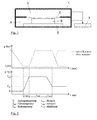
- FIG. 1 This shows very schematically a vacuum laminator 1, the interior of which is subdivided into an upper chamber 3 and a lower chamber 4, which are separated airtight from one another by a flexible membrane 2. At the bottom of the lower chamber 4 there is a heating and / or cooling plate 5, on which rest the components of the solar module to be connected during the lamination process. In the FIG. 1 this is indicated by the obtained after lamination laminate 6.
- the pressing pressure in the lamination results from the difference between the chamber pressure to which the laminate 6 is exposed in the lower chamber 4 and the pressure prevailing in the upper chamber 3.
- the required pressure differences can be adjusted by the vacuum pump 7.
- the softening, melting and possibly crosslinking of the encapsulation material is a critical factor.
- the temperature in the laminate must be controlled in such a way that sufficiently softened or melted thermoplastic materials and crosslinking materials are cured and cured specifically.
- FIG. 2 shows an exemplary course of temperature and pressure in the two chambers during a vacuum lamination process for the production of solar modules.
- the light components frequently used as support structures for the solar modules are currently produced using different methods.
- a process for the production of lightweight components by means of thermoplastically deformable organo sheets or crosslinking prepreg materials is the so-called Rapid Double Diaphragm Process (RDDF).
- RDDF Rapid Double Diaphragm Process
- a mold with register pins under a membrane is used, with which the support structure is to obtain the desired shape ,
- the flat composite of the prepreg material is inserted between these and another membrane and evacuated the air between the membranes.
- the prepreg material is heated and pressed onto the mold by increasing the chamber pressure above the upper membrane. Subsequently, the chambers are ventilated and the component exposed and removed. It can then be post cured in an autoclave or other external heat sources.
- the production process of solar modules on support structures requires a high number of process steps and thus also a high expenditure of time.
- the solar module and the carrier structure must also be matched to one another with regard to the shaping.
- the object of the present invention is to provide a method for the lamination and shaping of solar modules on carrier structures, which manages with a smaller number of process steps and allows a three-dimensional shaping.
- one or more solar cells, printed conductors and one or more plastic films and a transparent front cover are provided in a known manner as components of a solar module and connected to a lamination process for forming the solar module.
- the method is characterized in that the individual components of the solar module for this purpose are introduced together with the support structure or a material precursor of the support structure between two pressing tools of a laminator, pressed against each other with the two pressing tools and interconnected via the lamination process.
- the lamination process is preferably carried out using at least one molding tool as a pressing tool or a correspondingly preformed rigid, transparent front cover, through which or through which the support structure with the solar module, a three-dimensional, i. non-plane or domed, shape gets.
- the production of the solar module is combined with the production of the support structure in a common manufacturing process.
- the production of the solar module and the production of the support structure preferably achtbauismes done here not decoupled from each other, but are carried out in a joint connection and possibly forming step.
- the lamination process in the proposed method is also done by vacuum lamination.
- both rigid molds and flexible membranes can be used as pressing tools both rigid molds and flexible membranes. A combination of both types of tools is possible.
- a suitably designed molding tool can be used, against which the components of the solar module are pressed with the support structure or its precursor during the lamination.
- Another possibility is the use of an already correspondingly preformed transparent front cover, which must be rigid in this case and have sufficient strength. The other components and the support structure or its precursor are then in the lamination against this rigid front cover pressed, which in this case assumes the function of a molding tool.
- thermoplastically deformable fiber composite material organic sheet
- thermally crosslinking prepreg material is preferably used in the proposed process.
- the support structure is formed by means of the RIDFT technique described above.
- the required for the support structure resin is injected immediately before pressing or during the pressing process for lamination in the fiber structure used to form the support structure.
- the proposed method also offers the possibility of enclosing the solar module laterally through the lightweight support or the support structure.
- the sides of the material layer (s) forming the subsequent carrier structure for example the prepreg or organic sheet, which project in this case, are laid around the edges of the components of the solar module.
- the semi-finished thermoplastic or prepreg functional elements such as metallic support components, and integrate them in the process with fixed.
- this structure is then pressed and connected to each other, so that after lamination a correspondingly enclosed by the support structure solar module is obtained.
- This integration of the solar module into the carrier increases the module reliability. As a rule, in the previous techniques only sticking of the solar module to the carrier can be realized.
- the proposed method can be carried out in a vacuum laminator, as in FIG. 1 is shown schematically and has already been explained in the introductory part of the description.
- that exists in the FIG. 1 represented laminate 6 from the components of the solar module and the support structure used.
- the temperature control can be done in a comparable manner, as shown in the FIG. 2 is shown and has already been explained.
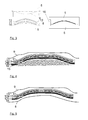
- FIG. 3 shows an example of an implementation of the proposed method in which a combination of double-diaphragm and vacuum lamination process is used.
- individual components of the laminator used can be seen.
- This has at the bottom of a heating and / or cooling plate 5, is attached to or above the lower membrane 8.
- the upper region of the lamination chamber also has a heating and / or cooling plate 5, at or below which in turn an upper membrane 9 is attached.
- the two lamination membranes 8, 9 may be formed, for example, from rubber or silicone.
- Upper and lower part of the laminator are connected to each other via a sealing frame 10.
- the individual components of the solar module in particular the solar cells 11, the encapsulation films 12 and the transparent front side cover 13, are placed over the material 14 for the support structure, in the present example a fiberglass back support.
- the Front cover 13 can basically be made of different materials, for example of glass, of ETFE or of PMMA.
- this front cover 13 is made of a rigid domed glass.
- the upper 9 and lower diaphragms 8 abut against this layer stack and are pressed against the three-dimensionally shaped front cover 13 by appropriate control of the pressure ratios in the upper and lower lamination chambers to take their shape.
- the two heating and / or cooling plates 5 are brought to an elevated temperature. In this case, therefore, the front cover 13 assumes the function of a mold, so that no corresponding mold is required more.
- the lamination process is in the right part of the FIG. 3 indicated. Subsequently, a cooling of the laminate and the two membranes are separated by appropriate pressure control in the chambers and lifting the upper part of the laminator again from the finished laminate 6, so that it can be removed from the laminator.
- the heat input can in principle also take place via radiant heat, so that it is possible to dispense with the cooling and / or heating plates. It is also possible, in addition to insert a flexible heating mat between the upper membrane 9 and front cover 13 and / or between the lower membrane 8 and substrate 14.
- FIG. 4 shows an example of the implementation of the proposed method, in which such a rigid mold 15 is used.
- this rigid mold 15 could also be used directly a component whose surface shape is to be imaged.
- An example of such a component is an area of an automobile skin.
- the individual flexible components of the solar module ie in this example the transparent front side cover 13, the solar cells 11, the front encapsulation film 12a and the back encapsulation film 12b, and the used carrier material 14, for example a not yet cured thermoset prepreg or a softened thermoplastic, are placed on the rigid tool 15.
- the heat required for the lamination is introduced either by thermal radiation from above, by the upper membrane 9 of the laminator or by the tool 15 itself.
- the encapsulation material ie, the upper 12a and lower encapsulation film 12b is melted or crosslinked and brought into the final state.
- the prepreg used as carrier material 14 is also crosslinked by the heat supply. If an already softened thermoplastic material is used as carrier material 14, it solidifies after completion of the process. The entire laminate stack will be during the Heating over the setting of a suitable pressure difference in the two chambers of the laminator through the upper diaphragm 9 is compressed.
- FIG. 6 shows another example, in which a rigid, already preformed front cover is used, which fulfills the function of a molding tool.
- the back side of the laminate stack ie the layer for the support structure, consists of a fiber fabric which, unlike a prepreg, has not yet been impregnated with resin.
- liquid resin is infused into the fiber layer 16 via a feed 18 and an inlet stub 17. Due to the negative pressure applied between the membranes 8, 9, the resin can impregnate the fiber fabric 16 accordingly.
- infusion and crosslinking which is accelerated by heat, creates a rigid support for the overlying solar module.
- This technique of resin infusion can of course also with a procedure as in FIG. 3 respectively.
- FIG. 5 be combined.
Landscapes
- Physics & Mathematics (AREA)
- Fluid Mechanics (AREA)
- Casting Or Compression Moulding Of Plastics Or The Like (AREA)
- Photovoltaic Devices (AREA)
Abstract
Description
- Die vorliegende Erfindung betrifft ein Verfahren zur Lamination und Formung von Solarmodulen auf Trägerstrukturen aus einem thermomechanisch formbaren Material, bei dem eine oder mehrere Solarzellen, Leiterbahnen und Kunststofffolien sowie eine transparente Frontabdeckung als Komponenten eines Solarmoduls bereitgestellt und mit einem Laminationsprozess zur Bildung des Solarmoduls verbunden werden.
- Solarmodule bestehen aus mehreren Einzelkomponenten, die in der Regel über einen Laminationsprozess miteinander verbunden werden. Hierbei werden eine oder mehrere Solarzellen sowie die zugehörigen Leiterbahnen bzw. Metallisierungen zwischen zwei Kunststofffolien als Verkapselungsmaterial platziert, welche von einem Frontglas und ggf. einer Rückseitenfolie oder einem Rückseitenglas abgeschlossen werden. Im Laminationsprozess werden diese Komponenten dann miteinander verbunden. Dünnschicht-Solarmodule oder zellbasierte Module in der Gebäudeintegration werden häufig nur mit einer Lage Verkapselungsfolie laminiert, da die Solarzellen in diesem Fall direkt auf dem Frontglas oder auf dem Rückseitenglas oder der Rückseitenfolie aufgebracht sind. Das auf diese Weise hergestellte Solarmodul wird dann auf eine dafür vorgesehene Trägerstruktur wie beispielsweise einen Aluminiumrahmen aufgebracht und an dieser befestigt. Die Trägerstruktur dient der mechanischen Versteifung des Solarmoduls. Als Trägerstrukturen eignen sich besonders Leichtbauteile, die bspw. auch mittels thermoplastisch verformbarer Organobleche oder vernetzender Prepreg-Materialien hergestellt werden können.
- Die Verbindung der einzelnen Komponenten eines Solarmoduls erfolgt zumeist in einem Vakuumlaminationsprozess. Die einzelnen Komponenten werden dabei im Laminator übereinander platziert und anschließend bei einem Umgebungsdruck von < 1 hPa aufgeheizt und mittels einer Membran zu einem festen Laminatverbund verpresst.
Figur 1 zeigt hierbei stark schematisiert einen Vakuumlaminator 1, dessen Innenraum in eine obere Kammer 3 und eine untere Kammer 4 unterteilt ist, die durch eine flexible Membran 2 luftdicht voneinander getrennt sind. Am Boden der unteren Kammer 4 befindet sich eine Heizund/oder Kühlplatte 5, auf der die zu verbindenden Komponenten des Solarmoduls während des Laminationsprozesses aufliegen. In derFigur 1 ist dies durch das nach der Lamination erhaltene Laminat 6 angedeutet. Der Pressdruck bei der Lamination ergibt sich aus dem Unterschied zwischen dem Kammerdruck, welchem das Laminat 6 in der unteren Kammer 4 ausgesetzt ist, und dem Druck, welcher in der oberen Kammer 3 herrscht. Die erforderlichen Druckunterschiede können durch die Vakuumpumpe 7 eingestellt werden. Das Erweichen, Aufschmelzen und ggf. Vernetzen des Verkapselungsmaterials stellt dabei einen kritischen Faktor dar. Die Temperatur im Laminat muss derart geführt werden, dass thermoplastische Materialien genügend erweicht oder aufgeschmolzen und vernetzende Materialien gezielt ausgehärtet und vernetzt werden.Figur 2 zeigt hierzu einen beispielhaften Verlauf von Temperatur und Druck in den beiden Kammern während eines Vakuumlaminationsprozesses zur Herstellung von Solarmodulen. - Die als Trägerstrukturen für die Solarmodule häufig eingesetzten Leichtbauteile werden derzeit mit unterschiedlichen Verfahren hergestellt. Ein Verfahren zur Herstellung von Leichtbauteilen mittels thermoplastisch verformbarer Organobleche oder vernetzender Prepreg-Materialien stellt der sog. Rapid Double Diaphragm Prozess (RDDF) dar. Bei diesem Verfahren wird ein Formwerkzeug mit Registerstiften unter einer Membran eingesetzt, mit dem die Trägerstruktur die gewünschte Form erhalten soll. Der flache Verbund des Prepreg-Materials wird zwischen diese und eine weitere Membran eingelegt und die Luft zwischen den Membranen evakuiert. Das Prepreg-Material wird aufgeheizt und durch Erhöhung des Kammerdrucks über der oberen Membran auf das Formwerkzeug aufgepresst. Anschließend werden die Kammern belüftet und das Bauteil freigelegt und entnommen. Es kann dann in einem Autoklaven oder durch andere externe Wärmequellen nachgehärtet werden.
- Eine weitere Technik zur Herstellung von Leichtbau-Trägerstrukturen für Solarmodule stellt die sog. Resin Infusion zwischen doppelt flexiblen Membranen (RIDFT) dar. Dies ist ein zweistufiges Verfahren, bei der eine Harzinfusion und Benetzung in einer ersten Stufe, gefolgt von Vakuumformen in einer zweiten Stufe erfolgt. Die Verstärkungsfasern für das Leichtbauteil werden dabei zwischen zwei Membranen gelegt. Nach der Sicherung der Membranen wird Harz unter Druck und Vakuum in den zwischen den beiden Membranen gebildeten Hohlraum mit den Verstärkungsfasern infusioniert. Anschließend erfolgt der Schritt des Vakuumformens, bei dem die Membranen mit den getränkten Verstärkungsfasern unter Vakuum über eine männliche Form gezogen werden. Die Verwendung einer einseitigen Form bietet deutliche Kostenvorteile gegenüber dem bekannten Verfahren des Resin Transfer Moulding (RTM). Die endgültige Formgebung kann dadurch erheblich beschleunigt werden. Weiterhin ist die Form nicht in Kontakt mit dem Harz oder der Verstärkung wodurch deren Verschleiß deutlich reduziert wird.
- Durch die obigen Schritte zur Herstellung der Solarmodule, der Leichtbauträgerstrukturen sowie der noch erforderlichen Verbindung der Solarmodule mit den Trägerstrukturen erfordert der Herstellungsprozess von Solarmodulen auf Trägerstrukturen eine hohe Anzahl von Prozessschritten und damit auch einen hohen Zeitaufwand. Für eine dreidimensionale Formgebung müssen das Solarmodul und die Trägerstruktur zudem hinsichtlich der Formgebung entsprechend aufeinander abgestimmt werden.
- Die Aufgabe der vorliegenden Erfindung besteht darin, ein Verfahren zur Lamination und Formung von Solarmodulen auf Trägerstrukturen anzugeben, das mit einer geringeren Anzahl von Prozessschritten auskommt und eine dreidimensionale Formgebung ermöglicht.
- Die Aufgabe wird mit dem Verfahren gemäß Patentanspruch 1 gelöst. Vorteilhafte Ausgestaltungen des Verfahrens sind Gegenstand der abhängigen Patentansprüche oder lassen sich der nachfolgenden Beschreibung sowie den Ausführungsbeispielen entnehmen.
- Bei dem vorgeschlagenen Verfahren werden in bekannter Weise eine oder mehrere Solarzellen, Leiterbahnen und eine oder mehrere Kunststofffolien sowie eine transparente Frontabdeckung als Komponenten eines Solarmoduls bereitgestellt und mit einem Laminationsprozess zur Bildung des Solarmoduls verbunden. Das Verfahren zeichnet sich dadurch aus, dass die einzelnen Komponenten des Solarmoduls hierzu zusammen mit der Trägerstruktur oder einer Materialvorstufe der Trägerstruktur zwischen zwei Presswerkzeuge eines Laminators eingebracht, mit den beiden Presswerkzeugen gegeneinander gepresst und über den Laminationsprozess miteinander verbunden werden. Der Laminationsprozess erfolgt dabei vorzugsweise unter Einsatz wenigstens eines Formwerkzeugs als Presswerkzeug oder einer entsprechend vorgeformten starren, transparenten Frontabdeckung, durch das oder durch die die Trägerstruktur mit dem Solarmodul eine dreidimensionale, d.h. nicht-plane oder gewölbte, Form erhält.
- Bei dem vorgeschlagenen Verfahren wird somit die Herstellung des Solarmoduls mit der Herstellung der Trägerstruktur in einem gemeinsamen Herstellungsprozess kombiniert. Die Herstellung des Solarmoduls und die Herstellung der Trägerstruktur, vorzugsweise eines Leichtbauträgers, erfolgen dabei nicht entkoppelt voneinander, sondern werden in einem gemeinsamen Verbindungs- und ggf. Formungsschritt durchgeführt.
- Durch diese Kombination der Herstellung des Solarmoduls und der Herstellung der Trägerstruktur sowie der Verbindung des Solarmoduls mit der Trägerstruktur in einem einzigen Laminationsprozess wird eine erhebliche Reduktion der Prozessschritte gegenüber der bisherigen Vorgehensweise erreicht. Dies führt auch zu einer erheblichen Verkürzung der Prozesszeiten sowie geringeren Energiekosten und erleichtert die dreidimensionale Formung des Gesamtsystems, d.h. des Solarmoduls mit der Trägerstruktur.
- Vorzugsweise erfolgt der Laminationsprozess bei dem vorgeschlagenen Verfahren ebenfalls durch Vakuumlamination. Je nach Ausgestaltung des Verfahrens können als Presswerkzeuge dabei sowohl starre Formwerkzeuge als auch flexible Membranen eingesetzt werden. Auch eine Kombination beider Werkzeugtypen ist möglich.
- Für die Erzeugung einer dreidimensionalen Form kann bspw. ein entsprechend ausgebildetes Formwerkzeug eingesetzt werden, gegen das die Komponenten des Solarmoduls mit der Trägerstruktur bzw. deren Vorstufe bei der Lamination gepresst werden. Eine andere Möglichkeit besteht in der Verwendung einer bereits entsprechend vorgeformten transparenten Frontabdeckung, die in diesem Fall starr ausgebildet und eine ausreichende Festigkeit aufweisen muss. Die weiteren Komponenten sowie die Trägerstruktur bzw. deren Vorstufe werden dann bei der Lamination gegen diese starre Frontabdeckung gepresst, die in diesem Fall die Funktion eines Formwerkzeuges übernimmt.
- Als Material der Trägerstruktur oder der Vorstufe der Trägerstruktur wird beim vorgeschlagenen Verfahren vorzugsweise ein thermoplastisch verformbarer Faserverbundwerkstoff (Organoblech) oder ein thermisch vernetzendes Prepreg-Material eingesetzt.
- In einer Ausgestaltung des vorgeschlagenen Verfahrens wird die Trägerstruktur mit Hilfe der eingangs beschriebenen RIDFT-Technik geformt. Hierzu wird das für die Trägerstruktur erforderliche Harz unmittelbar vor dem Anpressen oder während des Pressvorganges zur Lamination in das zur Bildung der Trägerstruktur genutzte Fasergelege injiziert.
- Das vorgeschlagene Verfahren bietet auch die Möglichkeit, das Solarmodul seitlich durch den Leichtbauträger bzw. die Trägerstruktur einzufassen. Hierzu werden bei dem Einlegen der einzelnen Komponenten in den Laminator die in diesem Falle überstehenden Seiten der die spätere Trägerstruktur bildenden Materiallage(n), bspw. des Prepregs oder Organoblechs, um die Ränder der Komponenten des Solarmoduls gelegt. Zusätzlich besteht die Möglichkeit, in die Halbzeuge aus Thermoplast oder Prepreg Funktionselemente, z.B. metallische Halterungskomponenten, einzulegen und diese im Prozess mit fest zu integrieren. Beim anschließenden Laminationsprozess wird dieser Aufbau dann verpresst und miteinander verbunden, so dass nach der Lamination ein entsprechend durch die Trägerstruktur eingefasstes Solarmodul erhalten wird. Durch diese Integration des Solarmoduls in den Träger wird die Modulzuverlässigkeit erhöht. In der Regel ist bei den bisherigen Techniken nur ein Aufkleben des Solarmoduls auf den Träger realisierbar.
- Das vorgeschlagene Verfahren wird nachfolgend anhand von Ausführungsbeispielen in Verbindung mit den Zeichnungen nochmals näher erläutert. Hierbei zeigen:
- Fig. 1
- eine schematische Darstellung eines Vakuumlaminators;
- Fig. 2
- eine schematische Darstellung des Druckund Temperaturverlaufs während eines Vakuumlaminationsprozesses;
- Fig. 3
- ein Beispiel für eine Kombination von Doppel-Diaphragma- und Vakuumlaminationsprozess;
- Fig. 4
- ein Beispiel für eine Durchführung des Verfahrens mit starrem Werkzeug oder abzubildender Oberfläche;
- Fig. 5
- ein Beispiel für eine Durchführung des vorgeschlagenen Verfahrens mit starrer Frontseitenabdeckung ohne Werkzeug; und
- Fig. 6
- ein Beispiel für eine Durchführung des vorgeschlagenen Verfahrens mit starrer Frontseitenabdeckung und Harz-Infusion.
- Das vorgeschlagene Verfahren lässt sich in einem Vakuumlaminator durchführen, wie er in
Figur 1 schematisch dargestellt ist und bereits im einleitenden Teil der Beschreibung erläutert wurde. In diesem Fall besteht das in derFigur 1 dargestellte Laminat 6 aus den Komponenten des Solarmoduls sowie der eingesetzten Trägerstruktur. Auch die Temperaturführung kann in vergleichbarer Weise erfolgen, wie dies in derFigur 2 dargestellt ist und bereits erläutert wurde. -
Figur 3 zeigt ein Beispiel einer Durchführung des vorgeschlagenen Verfahrens bei der eine Kombination aus Doppel-Diaphragma- und Vakuumlaminationsprozess eingesetzt wird. Im linken Teil der Figur sind hierbei einzelne Komponenten des eingesetzten Laminators zu erkennen. Dieser weist am Boden eine Heiz- und/oder Kühlplatte 5 auf, an oder über der eine untere Membran 8 befestigt ist. Der obere Bereich der Laminationskammer weist ebenfalls eine Heiz- und/oder Kühlplatte 5 auf, an oder unter der wiederum eine obere Membran 9 befestigt ist. Die beiden Laminationsmembranen 8, 9 können beispielsweise aus Gummi oder Silikon gebildet sein. Ober- und Unterteil des Laminators werden über einen Dichtrahmen 10 miteinander verbunden. Die einzelnen Komponenten des Solarmoduls, insbesondere die Solarzellen 11, die Verkapselungsfolien 12 sowie die transparente Frontseitenabdeckung 13, werden über dem Material 14 für die Trägerstruktur, im vorliegenden Beispiel einem GFK-Rückseitenträger, platziert. Dies ist im Detail auch nochmals inFigur 5 dargestellt. Die Frontseitenabdeckung 13 kann grundsätzlich aus unterschiedlichen Materialien, bspw. aus Glas, aus ETFE oder aus PMMA, gebildet sein. - Im vorliegenden Beispiel besteht diese Frontseitenabdeckung 13 aus einem starren gewölbten Glas. Bei der Durchführung des Laminationsprozesses legen sich die obere 9 und untere Membran 8 an diesen Schichtstapel an und werden über geeignete Steuerung der Druckverhältnisse in der oberen und unteren Laminationskammer gegen die dreidimensional geformte Frontseitenabdeckung 13 gepresst, um deren Form anzunehmen. Hierbei werden die beiden Heiz- und/oder Kühlplatten 5 auf eine erhöhte Temperatur gebracht. In diesem Fall übernimmt somit die Frontseitenabdeckung 13 die Funktion eines Formwerkzeugs, so dass kein entsprechendes Formwerkzeug mehr erforderlich ist.
- Der Laminationsvorgang ist im rechten Teil der
Figur 3 angedeutet. Anschließend erfolgt eine Abkühlung des Laminats und die beiden Membranen werden durch entsprechende Drucksteuerung in den Kammern und Abheben des oberen Teils des Laminators wieder vom fertigen Laminat 6 getrennt, so dass dieses aus dem Laminator entnommen werden kann. - Der Wärmeeintrag kann prinzipiell auch über Strahlungswärme erfolgen, so dass auf die Kühl- und/oder Heizplatten verzichtet werden kann. Weiterhin besteht die Möglichkeit, zusätzlich eine flexible Heizmatte zwischen obere Membran 9 und Frontabdeckung 13 und/oder zwischen untere Membran 8 und Trägermaterial 14 einzulegen.
- Alternativ besteht auch die Möglichkeit, anstelle einer bereits vorgeformten starren Frontseitenabdeckung und der unteren Membran 9 ein starres Formwerkzeug einzusetzen, durch das die gewünschte dreidimensionale Form bei der Lamination vorgegeben wird.
-
Figur 4 zeigt ein Beispiel für die Durchführung des vorgeschlagenen Verfahrens, bei der ein derart starres Formwerkzeug 15 eingesetzt wird. Anstelle dieses starren Formwerkzeuges 15 könnte auch direkt ein Bauteil eingesetzt werden, dessen Oberflächenform abgebildet werden soll. Ein Beispiel für ein derartiges Bauteil ist ein Bereich einer Automobil-Außenhaut. Die einzelnen flexiblen Komponenten des Solarmoduls, d.h. in diesem Beispiel die transparente Frontseitenabdeckung 13, die Solarzellen 11, die vorderseitige Verkapselungsfolie 12a sowie die rückseitige Verkapselungsfolie 12b, und das eingesetzte Trägermaterial 14, bspw. ein noch nicht ausgehärtetes Duromer-Prepreg oder ein erweichter Thermoplast, werden auf das starre Werkzeug 15 aufgelegt. Die für die Lamination erforderliche Wärme wird entweder durch Wärmestrahlung von oben, durch die obere Membran 9 des Laminators oder durch das Werkzeug 15 selbst eingebracht. Hierdurch wird das Verkapselungsmaterial, d.h. die obere 12a und untere Verkapselungsfolie 12b aufgeschmolzen oder vernetzt und in den finalen Zustand gebracht. Gleichzeitig wird durch die Wärmezufuhr auch das als Trägermaterial 14 eingesetzte Prepreg vernetzt. Wird als Trägermaterial 14 ein bereits erweichter Thermoplast verwendet, so erstarrt dieser nach Abschluss des Prozesses. Der gesamte Laminatstapel wird während der Erwärmung über die Einstellung eines geeigneten Druckunterschieds in den beiden Kammern des Laminators durch die obere Membran 9 verpresst. -
Figur 6 zeigt ein weiteres Beispiel, bei der eine starre, bereits vorgeformte Frontseitenabdeckung eingesetzt wird, die die Funktion eines Formwerkzeuges erfüllt. In diesem Fall besteht die Rückseite des Laminatstapels, d.h. die Schicht für die Trägerstruktur, aus einem Fasergelege, welches im Gegensatz zu einem Prepreg noch nicht mit Harz getränkt ist. Nach dem Anpressen des Gesamtstapels durch die Membranen 8, 9 an die starre Frontabdeckung 13 wird über eine Zuführung 18 und einen Einlassstutzen 17 flüssiges Harz in das Fasergelege 16 infusioniert. Durch den zwischen den Membranen 8, 9 angelegten Unterdruck kann das Harz das Fasergelege 16 entsprechend tränken. Nach Infusion und Vernetzung, welche durch Wärme beschleunigt wird, entsteht ein starrer Träger für das darüber liegende Solarmodul. Diese Technik der Harzinfusion kann selbstverständlich auch mit einer Verfahrensführung wie beiFigur 3 bzw.Figur 5 kombiniert werden. -
- 1
- Vakuumlaminator
- 2
- Membran
- 3
- obere Kammer
- 4
- untere Kammer
- 5
- Heiz- und/oder Kühlplatte
- 6
- Laminat
- 7
- Vakuumpumpe
- 8
- untere Membran
- 9
- obere Membran
- 10
- Dichtrahmen
- 11
- Solarzellen
- 12
- Verkapselungsfolien
- 12a
- obere Verkapselungsfolie
- 12b
- untere Verkapselungsfolie
- 13
- Frontseitenabdeckung
- 14
- Material für Trägerstruktur
- 15
- starres Formwerkzeug
- 16
- Fasergelege ohne Harz
- 17
- Einlassstuzen für Harzinfusion
- 18
- Harzzuführung
Claims (9)
- Verfahren zur Lamination und Formung von Solarmodulen auf Trägerstrukturen aus einem thermomechanisch formbaren Material, bei dem eine oder mehrere Solarzellen (11), Leiterbahnen und Kunststofffolien (12) sowie eine transparente Frontabdeckung (13) als Komponenten eines Solarmoduls bereitgestellt und mit einem Laminationsprozess zur Bildung des Solarmoduls verbunden werden,
dadurch gekennzeichnet,
dass die einzelnen Komponenten des Solarmoduls zunächst zusammen mit der Trägerstruktur (14) oder einer Materialvorstufe der Trägerstruktur (14) zwischen zwei Presswerkzeuge eines Laminators (1) eingebracht, mit den beiden Presswerkzeugen gegeneinandergepresst und über den Laminationsprozess miteinander und mit der Trägerstruktur (14) verbunden werden. - Verfahren nach Anspruch 1,
dadurch gekennzeichnet,
dass der Laminationsprozess unter Einsatz eines Formwerkzeugs (15) als eines der Presswerkzeuge erfolgt, durch das die Trägerstruktur (14) mit dem Solarmodul eine dreidimensionale Form erhält. - Verfahren nach Anspruch 1,
dadurch gekennzeichnet,
dass der Laminationsprozess unter Einsatz einer dreidimensional geformten starren, transparenten Frontabdeckung (13) erfolgt, durch die die Trägerstruktur (14) mit dem Solarmodul eine dreidimensionale Form erhält. - Verfahren nach einem der Ansprüche 1 bis 3,
dadurch gekennzeichnet,
dass die Verbindung der Komponenten des Solarmoduls und der Trägerstruktur (14) mit einem Vakuumlaminationsprozess erfolgt. - Verfahren nach Anspruch 4,
dadurch gekennzeichnet,
dass eine flexible Membran (8) als eines der Presswerkzeuge eingesetzt wird. - Verfahren nach Anspruch 4,
dadurch gekennzeichnet,
dass flexible Membranen (8, 9) als Presswerkzeuge eingesetzt werden. - Verfahren nach einem der Ansprüche 1 bis 6,
dadurch gekennzeichnet,
dass als Material oder Materialvorstufe der Trägerstruktur (14) ein thermoplastisches oder thermisch vernetzendes Material eingesetzt wird. - Verfahren nach einem der Ansprüche 1 bis 7,
dadurch gekennzeichnet,
dass als Trägerstruktur (14) oder Materialvorstufe der Trägerstruktur (14) ein Organoblech oder ein Prepreg eingesetzt wird. - Verfahren nach einem der Ansprüche 1 bis 6,
dadurch gekennzeichnet,
dass als Materialvorstufe der Trägerstruktur (14) ein Fasergelege eingesetzt wird, in das unmittelbar vor Beginn oder während des Laminationsprozesses mit Hilfe der RIDFT-Technik Harz zur Bildung der Trägerstruktur (14) eingebracht wird.
Priority Applications (1)
| Application Number | Priority Date | Filing Date | Title |
|---|---|---|---|
| EP14196424.7A EP3028854B1 (de) | 2014-12-05 | 2014-12-05 | Verfahren zur Lamination und Formung von Solarmodulen auf Trägerstrukturen |
Applications Claiming Priority (1)
| Application Number | Priority Date | Filing Date | Title |
|---|---|---|---|
| EP14196424.7A EP3028854B1 (de) | 2014-12-05 | 2014-12-05 | Verfahren zur Lamination und Formung von Solarmodulen auf Trägerstrukturen |
Publications (2)
| Publication Number | Publication Date |
|---|---|
| EP3028854A1 true EP3028854A1 (de) | 2016-06-08 |
| EP3028854B1 EP3028854B1 (de) | 2017-08-30 |
Family
ID=52006897
Family Applications (1)
| Application Number | Title | Priority Date | Filing Date |
|---|---|---|---|
| EP14196424.7A Not-in-force EP3028854B1 (de) | 2014-12-05 | 2014-12-05 | Verfahren zur Lamination und Formung von Solarmodulen auf Trägerstrukturen |
Country Status (1)
| Country | Link |
|---|---|
| EP (1) | EP3028854B1 (de) |
Cited By (5)
| Publication number | Priority date | Publication date | Assignee | Title |
|---|---|---|---|---|
| CN108550659A (zh) * | 2018-06-08 | 2018-09-18 | 北京汉能光伏投资有限公司 | 一种层压装置 |
| CN108767029A (zh) * | 2018-04-16 | 2018-11-06 | 无锡英富光能有限公司 | 一种用于建筑屋顶的太阳能电池组件及封装工艺 |
| EP3498452A3 (de) * | 2017-12-18 | 2019-08-28 | Ricoh Company, Ltd. | Verfahren und vorrichtung zum bilden einer dreidimensionalen gekrümmten oberfläche auf einem laminierten substrat und ein dreidimensionales gekrümmtes laminiertes substrat |
| DE102023100868A1 (de) * | 2022-08-02 | 2024-02-08 | Sunmaxx PVT GmbH | Formkörper und Verfahren für ein Photovoltaik-Modul |
| DE102018131704B4 (de) | 2017-12-13 | 2025-02-27 | Kabushiki Kaisha Toyota Jidoshokki | Verfahren zum Herstellen eines Solarpanels |
Citations (4)
| Publication number | Priority date | Publication date | Assignee | Title |
|---|---|---|---|---|
| EP2441556A2 (de) * | 2010-10-12 | 2012-04-18 | Deutsches Zentrum für Luft- und Raumfahrt e.V. | Verfahren zur Fertigung von Bauteilen in einem druckdichten Formwerkzeug und druckdichtes Formwerkzeug dafür |
| US20130071961A1 (en) * | 2011-09-20 | 2013-03-21 | James Michael Kostka | Large area hermetic encapsulation of an optoelectronic device using vacuum lamination |
| EP2698829A1 (de) * | 2012-08-13 | 2014-02-19 | tesa AG | Verfahren zur Herstellung eines Solarmoduls |
| EP2804224A1 (de) * | 2013-05-13 | 2014-11-19 | Fraunhofer Gesellschaft zur Förderung der angewandten Forschung e.V. | Verfahren zur Herstellung eines Photovoltaikmoduls |
-
2014
- 2014-12-05 EP EP14196424.7A patent/EP3028854B1/de not_active Not-in-force
Patent Citations (4)
| Publication number | Priority date | Publication date | Assignee | Title |
|---|---|---|---|---|
| EP2441556A2 (de) * | 2010-10-12 | 2012-04-18 | Deutsches Zentrum für Luft- und Raumfahrt e.V. | Verfahren zur Fertigung von Bauteilen in einem druckdichten Formwerkzeug und druckdichtes Formwerkzeug dafür |
| US20130071961A1 (en) * | 2011-09-20 | 2013-03-21 | James Michael Kostka | Large area hermetic encapsulation of an optoelectronic device using vacuum lamination |
| EP2698829A1 (de) * | 2012-08-13 | 2014-02-19 | tesa AG | Verfahren zur Herstellung eines Solarmoduls |
| EP2804224A1 (de) * | 2013-05-13 | 2014-11-19 | Fraunhofer Gesellschaft zur Förderung der angewandten Forschung e.V. | Verfahren zur Herstellung eines Photovoltaikmoduls |
Cited By (7)
| Publication number | Priority date | Publication date | Assignee | Title |
|---|---|---|---|---|
| DE102018131704B4 (de) | 2017-12-13 | 2025-02-27 | Kabushiki Kaisha Toyota Jidoshokki | Verfahren zum Herstellen eines Solarpanels |
| EP3498452A3 (de) * | 2017-12-18 | 2019-08-28 | Ricoh Company, Ltd. | Verfahren und vorrichtung zum bilden einer dreidimensionalen gekrümmten oberfläche auf einem laminierten substrat und ein dreidimensionales gekrümmtes laminiertes substrat |
| US11833800B2 (en) | 2017-12-18 | 2023-12-05 | Ricoh Company, Ltd. | Method and apparatus for forming three-dimensional curved surface on laminated substrate, and three-dimensional curved laminated substrate |
| CN108767029A (zh) * | 2018-04-16 | 2018-11-06 | 无锡英富光能有限公司 | 一种用于建筑屋顶的太阳能电池组件及封装工艺 |
| CN108767029B (zh) * | 2018-04-16 | 2020-09-11 | 无锡和家光能有限公司 | 一种用于建筑屋顶的太阳能电池组件及封装工艺 |
| CN108550659A (zh) * | 2018-06-08 | 2018-09-18 | 北京汉能光伏投资有限公司 | 一种层压装置 |
| DE102023100868A1 (de) * | 2022-08-02 | 2024-02-08 | Sunmaxx PVT GmbH | Formkörper und Verfahren für ein Photovoltaik-Modul |
Also Published As
| Publication number | Publication date |
|---|---|
| EP3028854B1 (de) | 2017-08-30 |
Similar Documents
| Publication | Publication Date | Title |
|---|---|---|
| EP3365158B1 (de) | Verfahren zum herstellen eines bauteils aus einem faserverbundwerkstoff | |
| EP3028854B1 (de) | Verfahren zur Lamination und Formung von Solarmodulen auf Trägerstrukturen | |
| JP4363741B2 (ja) | 繊維強化複合材からなる中間成形物品の製造方法 | |
| DE102014100035B4 (de) | Verbundwerkstoff-konstruktionsplatte und verfahren zum bilden solch einer platte | |
| DE69809522T2 (de) | Verfahren zum Formen eines inneren Druckstücks während des Formen eines Produktes | |
| EP2274158B1 (de) | Verfahren und Umformvorrichtung zur Herstellung eines Faserverbundbauteils für die Luft- und Raumfahrt | |
| DE102010050740B4 (de) | Verfahren und Vorrichtung zur Herstellung eines Flugzeugstrukturbauteils | |
| DE69320772T2 (de) | Verfahren zum Herstellen von Verbundverbindungen für fachwerkartige Struktur oder Fachwerkteile, und so hergestellte Fachwerke | |
| DE102022101935A1 (de) | Verfahren zur Herstellung eines photovoltaischen Panels, wie z.B. eines in die Fahrzeugkarosserie integrierten PV-Panels, unter Verwendung eines wärmehärtenden Polymers | |
| EP3408075B1 (de) | Verfahren zum herstellen eines bauteils aus einem faserverbundwerkstoff | |
| DE102007026099A1 (de) | Vorrichtung und Verfahren zum Bearbeiten einer Faserverbundstruktur | |
| EP2984701A1 (de) | Wärmeübertragerbauteil | |
| EP2436512B1 (de) | Verfahren zur Erstellung eines Vakuumaufbaus für die Herstellung eines Faserverbundbauteils sowie hierfür geeigneter Stempel | |
| DE602005001132T2 (de) | Geformter Schichtstoff und Verfahren zu dessen Herstellung | |
| EP0465719A2 (de) | Flächiger Gegenstand mit Wabenstruktur und Verfahren zu dessen Herstellung | |
| EP3408080A1 (de) | Presse zum herstellen eines bauteils aus einem faserverbundwerkstoff | |
| DE102008036349B4 (de) | Verfahren und Vorrichtung zur Herstellung einer Struktur, insbesondere einer Flugzeugstruktur aus einem Faserverbundwerkstoff | |
| EP2890552A1 (de) | Verfahren zur fertigung eines rotorblattes und ein rotorblatt einer windenergieanlage | |
| WO2017129395A1 (de) | Presse zum herstellen eines bauteils aus einem faserverbundwerkstoff | |
| DE102005003713B4 (de) | Verfahren zur Herstellung von faserverstärkten Hohlkörperkern-Sandwichbauteilen im vakuumunterstützten Harz-Infusionsprozess | |
| EP3651989B1 (de) | Laminiervorrichtung und verfahren zum laminieren wenigstens eines schichtenstapels | |
| DE102017119541A1 (de) | Kern-Mantel Halbzeug | |
| DE102010061294A1 (de) | Laminierung von 3D-Solarbauteilen | |
| DE102020108246B4 (de) | Verfahren zum Herstellen eines Faserverbundbauteils | |
| WO2022229197A1 (de) | Fluggerätgrundkörper |
Legal Events
| Date | Code | Title | Description |
|---|---|---|---|
| PUAI | Public reference made under article 153(3) epc to a published international application that has entered the european phase |
Free format text: ORIGINAL CODE: 0009012 |
|
| AK | Designated contracting states |
Kind code of ref document: A1 Designated state(s): AL AT BE BG CH CY CZ DE DK EE ES FI FR GB GR HR HU IE IS IT LI LT LU LV MC MK MT NL NO PL PT RO RS SE SI SK SM TR |
|
| AX | Request for extension of the european patent |
Extension state: BA ME |
|
| 17P | Request for examination filed |
Effective date: 20161025 |
|
| RBV | Designated contracting states (corrected) |
Designated state(s): AL AT BE BG CH CY CZ DE DK EE ES FI FR GB GR HR HU IE IS IT LI LT LU LV MC MK MT NL NO PL PT RO RS SE SI SK SM TR |
|
| GRAP | Despatch of communication of intention to grant a patent |
Free format text: ORIGINAL CODE: EPIDOSNIGR1 |
|
| INTG | Intention to grant announced |
Effective date: 20170330 |
|
| GRAS | Grant fee paid |
Free format text: ORIGINAL CODE: EPIDOSNIGR3 |
|
| GRAA | (expected) grant |
Free format text: ORIGINAL CODE: 0009210 |
|
| AK | Designated contracting states |
Kind code of ref document: B1 Designated state(s): AL AT BE BG CH CY CZ DE DK EE ES FI FR GB GR HR HU IE IS IT LI LT LU LV MC MK MT NL NO PL PT RO RS SE SI SK SM TR |
|
| REG | Reference to a national code |
Ref country code: GB Ref legal event code: FG4D Free format text: NOT ENGLISH |
|
| REG | Reference to a national code |
Ref country code: CH Ref legal event code: EP |
|
| REG | Reference to a national code |
Ref country code: AT Ref legal event code: REF Ref document number: 923126 Country of ref document: AT Kind code of ref document: T Effective date: 20170915 |
|
| REG | Reference to a national code |
Ref country code: IE Ref legal event code: FG4D Free format text: LANGUAGE OF EP DOCUMENT: GERMAN |
|
| REG | Reference to a national code |
Ref country code: DE Ref legal event code: R096 Ref document number: 502014005222 Country of ref document: DE |
|
| REG | Reference to a national code |
Ref country code: NL Ref legal event code: MP Effective date: 20170830 |
|
| REG | Reference to a national code |
Ref country code: LT Ref legal event code: MG4D |
|
| PG25 | Lapsed in a contracting state [announced via postgrant information from national office to epo] |
Ref country code: SE Free format text: LAPSE BECAUSE OF FAILURE TO SUBMIT A TRANSLATION OF THE DESCRIPTION OR TO PAY THE FEE WITHIN THE PRESCRIBED TIME-LIMIT Effective date: 20170830 Ref country code: HR Free format text: LAPSE BECAUSE OF FAILURE TO SUBMIT A TRANSLATION OF THE DESCRIPTION OR TO PAY THE FEE WITHIN THE PRESCRIBED TIME-LIMIT Effective date: 20170830 Ref country code: FI Free format text: LAPSE BECAUSE OF FAILURE TO SUBMIT A TRANSLATION OF THE DESCRIPTION OR TO PAY THE FEE WITHIN THE PRESCRIBED TIME-LIMIT Effective date: 20170830 Ref country code: NO Free format text: LAPSE BECAUSE OF FAILURE TO SUBMIT A TRANSLATION OF THE DESCRIPTION OR TO PAY THE FEE WITHIN THE PRESCRIBED TIME-LIMIT Effective date: 20171130 Ref country code: LT Free format text: LAPSE BECAUSE OF FAILURE TO SUBMIT A TRANSLATION OF THE DESCRIPTION OR TO PAY THE FEE WITHIN THE PRESCRIBED TIME-LIMIT Effective date: 20170830 |
|
| PG25 | Lapsed in a contracting state [announced via postgrant information from national office to epo] |
Ref country code: ES Free format text: LAPSE BECAUSE OF FAILURE TO SUBMIT A TRANSLATION OF THE DESCRIPTION OR TO PAY THE FEE WITHIN THE PRESCRIBED TIME-LIMIT Effective date: 20170830 Ref country code: GR Free format text: LAPSE BECAUSE OF FAILURE TO SUBMIT A TRANSLATION OF THE DESCRIPTION OR TO PAY THE FEE WITHIN THE PRESCRIBED TIME-LIMIT Effective date: 20171201 Ref country code: IS Free format text: LAPSE BECAUSE OF FAILURE TO SUBMIT A TRANSLATION OF THE DESCRIPTION OR TO PAY THE FEE WITHIN THE PRESCRIBED TIME-LIMIT Effective date: 20171230 Ref country code: RS Free format text: LAPSE BECAUSE OF FAILURE TO SUBMIT A TRANSLATION OF THE DESCRIPTION OR TO PAY THE FEE WITHIN THE PRESCRIBED TIME-LIMIT Effective date: 20170830 Ref country code: BG Free format text: LAPSE BECAUSE OF FAILURE TO SUBMIT A TRANSLATION OF THE DESCRIPTION OR TO PAY THE FEE WITHIN THE PRESCRIBED TIME-LIMIT Effective date: 20171130 Ref country code: LV Free format text: LAPSE BECAUSE OF FAILURE TO SUBMIT A TRANSLATION OF THE DESCRIPTION OR TO PAY THE FEE WITHIN THE PRESCRIBED TIME-LIMIT Effective date: 20170830 |
|
| PG25 | Lapsed in a contracting state [announced via postgrant information from national office to epo] |
Ref country code: NL Free format text: LAPSE BECAUSE OF FAILURE TO SUBMIT A TRANSLATION OF THE DESCRIPTION OR TO PAY THE FEE WITHIN THE PRESCRIBED TIME-LIMIT Effective date: 20170830 |
|
| PG25 | Lapsed in a contracting state [announced via postgrant information from national office to epo] |
Ref country code: DK Free format text: LAPSE BECAUSE OF FAILURE TO SUBMIT A TRANSLATION OF THE DESCRIPTION OR TO PAY THE FEE WITHIN THE PRESCRIBED TIME-LIMIT Effective date: 20170830 Ref country code: RO Free format text: LAPSE BECAUSE OF FAILURE TO SUBMIT A TRANSLATION OF THE DESCRIPTION OR TO PAY THE FEE WITHIN THE PRESCRIBED TIME-LIMIT Effective date: 20170830 Ref country code: CZ Free format text: LAPSE BECAUSE OF FAILURE TO SUBMIT A TRANSLATION OF THE DESCRIPTION OR TO PAY THE FEE WITHIN THE PRESCRIBED TIME-LIMIT Effective date: 20170830 Ref country code: PL Free format text: LAPSE BECAUSE OF FAILURE TO SUBMIT A TRANSLATION OF THE DESCRIPTION OR TO PAY THE FEE WITHIN THE PRESCRIBED TIME-LIMIT Effective date: 20170830 |
|
| PG25 | Lapsed in a contracting state [announced via postgrant information from national office to epo] |
Ref country code: EE Free format text: LAPSE BECAUSE OF FAILURE TO SUBMIT A TRANSLATION OF THE DESCRIPTION OR TO PAY THE FEE WITHIN THE PRESCRIBED TIME-LIMIT Effective date: 20170830 Ref country code: IT Free format text: LAPSE BECAUSE OF FAILURE TO SUBMIT A TRANSLATION OF THE DESCRIPTION OR TO PAY THE FEE WITHIN THE PRESCRIBED TIME-LIMIT Effective date: 20170830 Ref country code: SK Free format text: LAPSE BECAUSE OF FAILURE TO SUBMIT A TRANSLATION OF THE DESCRIPTION OR TO PAY THE FEE WITHIN THE PRESCRIBED TIME-LIMIT Effective date: 20170830 Ref country code: SM Free format text: LAPSE BECAUSE OF FAILURE TO SUBMIT A TRANSLATION OF THE DESCRIPTION OR TO PAY THE FEE WITHIN THE PRESCRIBED TIME-LIMIT Effective date: 20170830 |
|
| REG | Reference to a national code |
Ref country code: DE Ref legal event code: R097 Ref document number: 502014005222 Country of ref document: DE |
|
| PLBE | No opposition filed within time limit |
Free format text: ORIGINAL CODE: 0009261 |
|
| STAA | Information on the status of an ep patent application or granted ep patent |
Free format text: STATUS: NO OPPOSITION FILED WITHIN TIME LIMIT |
|
| REG | Reference to a national code |
Ref country code: CH Ref legal event code: PL |
|
| 26N | No opposition filed |
Effective date: 20180531 |
|
| PG25 | Lapsed in a contracting state [announced via postgrant information from national office to epo] |
Ref country code: SI Free format text: LAPSE BECAUSE OF FAILURE TO SUBMIT A TRANSLATION OF THE DESCRIPTION OR TO PAY THE FEE WITHIN THE PRESCRIBED TIME-LIMIT Effective date: 20170830 |
|
| REG | Reference to a national code |
Ref country code: IE Ref legal event code: MM4A |
|
| PG25 | Lapsed in a contracting state [announced via postgrant information from national office to epo] |
Ref country code: MT Free format text: LAPSE BECAUSE OF FAILURE TO SUBMIT A TRANSLATION OF THE DESCRIPTION OR TO PAY THE FEE WITHIN THE PRESCRIBED TIME-LIMIT Effective date: 20170830 Ref country code: LU Free format text: LAPSE BECAUSE OF NON-PAYMENT OF DUE FEES Effective date: 20171205 |
|
| REG | Reference to a national code |
Ref country code: FR Ref legal event code: ST Effective date: 20180831 |
|
| REG | Reference to a national code |
Ref country code: BE Ref legal event code: MM Effective date: 20171231 |
|
| PG25 | Lapsed in a contracting state [announced via postgrant information from national office to epo] |
Ref country code: IE Free format text: LAPSE BECAUSE OF NON-PAYMENT OF DUE FEES Effective date: 20171205 Ref country code: FR Free format text: LAPSE BECAUSE OF NON-PAYMENT OF DUE FEES Effective date: 20180102 |
|
| PG25 | Lapsed in a contracting state [announced via postgrant information from national office to epo] |
Ref country code: BE Free format text: LAPSE BECAUSE OF NON-PAYMENT OF DUE FEES Effective date: 20171231 Ref country code: CH Free format text: LAPSE BECAUSE OF NON-PAYMENT OF DUE FEES Effective date: 20171231 Ref country code: LI Free format text: LAPSE BECAUSE OF NON-PAYMENT OF DUE FEES Effective date: 20171231 |
|
| PGFP | Annual fee paid to national office [announced via postgrant information from national office to epo] |
Ref country code: DE Payment date: 20181220 Year of fee payment: 5 |
|
| PG25 | Lapsed in a contracting state [announced via postgrant information from national office to epo] |
Ref country code: MC Free format text: LAPSE BECAUSE OF FAILURE TO SUBMIT A TRANSLATION OF THE DESCRIPTION OR TO PAY THE FEE WITHIN THE PRESCRIBED TIME-LIMIT Effective date: 20170830 Ref country code: HU Free format text: LAPSE BECAUSE OF FAILURE TO SUBMIT A TRANSLATION OF THE DESCRIPTION OR TO PAY THE FEE WITHIN THE PRESCRIBED TIME-LIMIT; INVALID AB INITIO Effective date: 20141205 |
|
| GBPC | Gb: european patent ceased through non-payment of renewal fee |
Effective date: 20181205 |
|
| PG25 | Lapsed in a contracting state [announced via postgrant information from national office to epo] |
Ref country code: CY Free format text: LAPSE BECAUSE OF FAILURE TO SUBMIT A TRANSLATION OF THE DESCRIPTION OR TO PAY THE FEE WITHIN THE PRESCRIBED TIME-LIMIT Effective date: 20170830 |
|
| PG25 | Lapsed in a contracting state [announced via postgrant information from national office to epo] |
Ref country code: MK Free format text: LAPSE BECAUSE OF FAILURE TO SUBMIT A TRANSLATION OF THE DESCRIPTION OR TO PAY THE FEE WITHIN THE PRESCRIBED TIME-LIMIT Effective date: 20170830 |
|
| PG25 | Lapsed in a contracting state [announced via postgrant information from national office to epo] |
Ref country code: GB Free format text: LAPSE BECAUSE OF NON-PAYMENT OF DUE FEES Effective date: 20181205 |
|
| PG25 | Lapsed in a contracting state [announced via postgrant information from national office to epo] |
Ref country code: TR Free format text: LAPSE BECAUSE OF FAILURE TO SUBMIT A TRANSLATION OF THE DESCRIPTION OR TO PAY THE FEE WITHIN THE PRESCRIBED TIME-LIMIT Effective date: 20170830 |
|
| PG25 | Lapsed in a contracting state [announced via postgrant information from national office to epo] |
Ref country code: PT Free format text: LAPSE BECAUSE OF FAILURE TO SUBMIT A TRANSLATION OF THE DESCRIPTION OR TO PAY THE FEE WITHIN THE PRESCRIBED TIME-LIMIT Effective date: 20170830 |
|
| REG | Reference to a national code |
Ref country code: DE Ref legal event code: R119 Ref document number: 502014005222 Country of ref document: DE |
|
| PG25 | Lapsed in a contracting state [announced via postgrant information from national office to epo] |
Ref country code: AL Free format text: LAPSE BECAUSE OF FAILURE TO SUBMIT A TRANSLATION OF THE DESCRIPTION OR TO PAY THE FEE WITHIN THE PRESCRIBED TIME-LIMIT Effective date: 20170830 |
|
| PG25 | Lapsed in a contracting state [announced via postgrant information from national office to epo] |
Ref country code: DE Free format text: LAPSE BECAUSE OF NON-PAYMENT OF DUE FEES Effective date: 20200701 |
|
| REG | Reference to a national code |
Ref country code: AT Ref legal event code: MM01 Ref document number: 923126 Country of ref document: AT Kind code of ref document: T Effective date: 20191205 |
|
| PG25 | Lapsed in a contracting state [announced via postgrant information from national office to epo] |
Ref country code: AT Free format text: LAPSE BECAUSE OF NON-PAYMENT OF DUE FEES Effective date: 20191205 |