EP3028768B1 - A painting apparatus comprising an air bag - Google Patents
A painting apparatus comprising an air bag Download PDFInfo
- Publication number
- EP3028768B1 EP3028768B1 EP14197483.2A EP14197483A EP3028768B1 EP 3028768 B1 EP3028768 B1 EP 3028768B1 EP 14197483 A EP14197483 A EP 14197483A EP 3028768 B1 EP3028768 B1 EP 3028768B1
- Authority
- EP
- European Patent Office
- Prior art keywords
- paint
- bag
- air
- port
- air bag
- Prior art date
- Legal status (The legal status is an assumption and is not a legal conclusion. Google has not performed a legal analysis and makes no representation as to the accuracy of the status listed.)
- Not-in-force
Links
- 238000010422 painting Methods 0.000 title claims description 88
- 239000003973 paint Substances 0.000 claims description 325
- 230000007246 mechanism Effects 0.000 claims description 43
- 238000005086 pumping Methods 0.000 claims description 28
- 238000000926 separation method Methods 0.000 claims description 13
- 239000012528 membrane Substances 0.000 claims description 8
- 238000003825 pressing Methods 0.000 claims description 8
- 239000013013 elastic material Substances 0.000 claims description 7
- 230000004913 activation Effects 0.000 claims description 6
- 230000007423 decrease Effects 0.000 description 5
- 229920000642 polymer Polymers 0.000 description 5
- 241000870659 Crassula perfoliata var. minor Species 0.000 description 4
- 230000009471 action Effects 0.000 description 4
- 239000000463 material Substances 0.000 description 4
- 230000006835 compression Effects 0.000 description 3
- 238000007906 compression Methods 0.000 description 3
- 238000004140 cleaning Methods 0.000 description 2
- 239000003086 colorant Substances 0.000 description 2
- 230000008602 contraction Effects 0.000 description 2
- 238000009826 distribution Methods 0.000 description 2
- 238000012423 maintenance Methods 0.000 description 2
- 238000004519 manufacturing process Methods 0.000 description 2
- 229920003023 plastic Polymers 0.000 description 2
- 239000004033 plastic Substances 0.000 description 2
- NIXOWILDQLNWCW-UHFFFAOYSA-N acrylic acid group Chemical group C(C=C)(=O)O NIXOWILDQLNWCW-UHFFFAOYSA-N 0.000 description 1
- 239000002519 antifouling agent Substances 0.000 description 1
- 229920002457 flexible plastic Polymers 0.000 description 1
- 229920005570 flexible polymer Polymers 0.000 description 1
- 238000003780 insertion Methods 0.000 description 1
- 230000037431 insertion Effects 0.000 description 1
- 238000012986 modification Methods 0.000 description 1
- 230000004048 modification Effects 0.000 description 1
- 238000000465 moulding Methods 0.000 description 1
- 239000002861 polymer material Substances 0.000 description 1
- 230000009467 reduction Effects 0.000 description 1
- 238000007789 sealing Methods 0.000 description 1
- 238000005507 spraying Methods 0.000 description 1
- 239000002023 wood Substances 0.000 description 1
Images


Classifications
-
- B—PERFORMING OPERATIONS; TRANSPORTING
- B05—SPRAYING OR ATOMISING IN GENERAL; APPLYING FLUENT MATERIALS TO SURFACES, IN GENERAL
- B05C—APPARATUS FOR APPLYING FLUENT MATERIALS TO SURFACES, IN GENERAL
- B05C17/00—Hand tools or apparatus using hand held tools, for applying liquids or other fluent materials to, for spreading applied liquids or other fluent materials on, or for partially removing applied liquids or other fluent materials from, surfaces
- B05C17/02—Rollers ; Hand tools comprising coating rollers or coating endless belts
- B05C17/03—Rollers ; Hand tools comprising coating rollers or coating endless belts with feed system for supplying material from an external source or with a reservoir or container for liquid or other fluent material located in or on the hand tool outside the coating roller
- B05C17/0316—Rollers ; Hand tools comprising coating rollers or coating endless belts with feed system for supplying material from an external source or with a reservoir or container for liquid or other fluent material located in or on the hand tool outside the coating roller with pressurised or compressible container
- B05C17/0325—Rollers ; Hand tools comprising coating rollers or coating endless belts with feed system for supplying material from an external source or with a reservoir or container for liquid or other fluent material located in or on the hand tool outside the coating roller with pressurised or compressible container attached to the hand tool, e.g. into the handle
-
- B—PERFORMING OPERATIONS; TRANSPORTING
- B05—SPRAYING OR ATOMISING IN GENERAL; APPLYING FLUENT MATERIALS TO SURFACES, IN GENERAL
- B05B—SPRAYING APPARATUS; ATOMISING APPARATUS; NOZZLES
- B05B9/00—Spraying apparatus for discharge of liquids or other fluent material, without essentially mixing with gas or vapour
- B05B9/03—Spraying apparatus for discharge of liquids or other fluent material, without essentially mixing with gas or vapour characterised by means for supplying liquid or other fluent material
- B05B9/04—Spraying apparatus for discharge of liquids or other fluent material, without essentially mixing with gas or vapour characterised by means for supplying liquid or other fluent material with pressurised or compressible container; with pump
- B05B9/047—Spraying apparatus for discharge of liquids or other fluent material, without essentially mixing with gas or vapour characterised by means for supplying liquid or other fluent material with pressurised or compressible container; with pump supply being effected by follower in container, e.g. membrane or floating piston, or by deformation of container
-
- B—PERFORMING OPERATIONS; TRANSPORTING
- B05—SPRAYING OR ATOMISING IN GENERAL; APPLYING FLUENT MATERIALS TO SURFACES, IN GENERAL
- B05B—SPRAYING APPARATUS; ATOMISING APPARATUS; NOZZLES
- B05B9/00—Spraying apparatus for discharge of liquids or other fluent material, without essentially mixing with gas or vapour
- B05B9/03—Spraying apparatus for discharge of liquids or other fluent material, without essentially mixing with gas or vapour characterised by means for supplying liquid or other fluent material
- B05B9/04—Spraying apparatus for discharge of liquids or other fluent material, without essentially mixing with gas or vapour characterised by means for supplying liquid or other fluent material with pressurised or compressible container; with pump
- B05B9/08—Apparatus to be carried on or by a person, e.g. of knapsack type
- B05B9/0805—Apparatus to be carried on or by a person, e.g. of knapsack type comprising a pressurised or compressible container for liquid or other fluent material
- B05B9/0811—Apparatus to be carried on or by a person, e.g. of knapsack type comprising a pressurised or compressible container for liquid or other fluent material comprising air supplying means actuated by the operator to pressurise or compress the container
-
- B—PERFORMING OPERATIONS; TRANSPORTING
- B05—SPRAYING OR ATOMISING IN GENERAL; APPLYING FLUENT MATERIALS TO SURFACES, IN GENERAL
- B05B—SPRAYING APPARATUS; ATOMISING APPARATUS; NOZZLES
- B05B9/00—Spraying apparatus for discharge of liquids or other fluent material, without essentially mixing with gas or vapour
- B05B9/03—Spraying apparatus for discharge of liquids or other fluent material, without essentially mixing with gas or vapour characterised by means for supplying liquid or other fluent material
- B05B9/04—Spraying apparatus for discharge of liquids or other fluent material, without essentially mixing with gas or vapour characterised by means for supplying liquid or other fluent material with pressurised or compressible container; with pump
- B05B9/08—Apparatus to be carried on or by a person, e.g. of knapsack type
- B05B9/0805—Apparatus to be carried on or by a person, e.g. of knapsack type comprising a pressurised or compressible container for liquid or other fluent material
- B05B9/0811—Apparatus to be carried on or by a person, e.g. of knapsack type comprising a pressurised or compressible container for liquid or other fluent material comprising air supplying means actuated by the operator to pressurise or compress the container
- B05B9/0816—Apparatus to be carried on or by a person, e.g. of knapsack type comprising a pressurised or compressible container for liquid or other fluent material comprising air supplying means actuated by the operator to pressurise or compress the container the air supplying means being a manually actuated air pump
-
- B—PERFORMING OPERATIONS; TRANSPORTING
- B05—SPRAYING OR ATOMISING IN GENERAL; APPLYING FLUENT MATERIALS TO SURFACES, IN GENERAL
- B05B—SPRAYING APPARATUS; ATOMISING APPARATUS; NOZZLES
- B05B9/00—Spraying apparatus for discharge of liquids or other fluent material, without essentially mixing with gas or vapour
- B05B9/03—Spraying apparatus for discharge of liquids or other fluent material, without essentially mixing with gas or vapour characterised by means for supplying liquid or other fluent material
- B05B9/04—Spraying apparatus for discharge of liquids or other fluent material, without essentially mixing with gas or vapour characterised by means for supplying liquid or other fluent material with pressurised or compressible container; with pump
- B05B9/08—Apparatus to be carried on or by a person, e.g. of knapsack type
- B05B9/0805—Apparatus to be carried on or by a person, e.g. of knapsack type comprising a pressurised or compressible container for liquid or other fluent material
- B05B9/0838—Apparatus to be carried on or by a person, e.g. of knapsack type comprising a pressurised or compressible container for liquid or other fluent material supply being effected by follower in container, e.g. membrane or floating piston, or by deformation of container
-
- B—PERFORMING OPERATIONS; TRANSPORTING
- B05—SPRAYING OR ATOMISING IN GENERAL; APPLYING FLUENT MATERIALS TO SURFACES, IN GENERAL
- B05C—APPARATUS FOR APPLYING FLUENT MATERIALS TO SURFACES, IN GENERAL
- B05C11/00—Component parts, details or accessories not specifically provided for in groups B05C1/00 - B05C9/00
- B05C11/10—Storage, supply or control of liquid or other fluent material; Recovery of excess liquid or other fluent material
- B05C11/1002—Means for controlling supply, i.e. flow or pressure, of liquid or other fluent material to the applying apparatus, e.g. valves
-
- B—PERFORMING OPERATIONS; TRANSPORTING
- B05—SPRAYING OR ATOMISING IN GENERAL; APPLYING FLUENT MATERIALS TO SURFACES, IN GENERAL
- B05C—APPARATUS FOR APPLYING FLUENT MATERIALS TO SURFACES, IN GENERAL
- B05C17/00—Hand tools or apparatus using hand held tools, for applying liquids or other fluent materials to, for spreading applied liquids or other fluent materials on, or for partially removing applied liquids or other fluent materials from, surfaces
- B05C17/002—Hand tools or apparatus using hand held tools, for applying liquids or other fluent materials to, for spreading applied liquids or other fluent materials on, or for partially removing applied liquids or other fluent materials from, surfaces with feed system for supplying material from an external source; Supply controls therefor
-
- B—PERFORMING OPERATIONS; TRANSPORTING
- B05—SPRAYING OR ATOMISING IN GENERAL; APPLYING FLUENT MATERIALS TO SURFACES, IN GENERAL
- B05C—APPARATUS FOR APPLYING FLUENT MATERIALS TO SURFACES, IN GENERAL
- B05C17/00—Hand tools or apparatus using hand held tools, for applying liquids or other fluent materials to, for spreading applied liquids or other fluent materials on, or for partially removing applied liquids or other fluent materials from, surfaces
- B05C17/005—Hand tools or apparatus using hand held tools, for applying liquids or other fluent materials to, for spreading applied liquids or other fluent materials on, or for partially removing applied liquids or other fluent materials from, surfaces for discharging material from a reservoir or container located in or on the hand tool through an outlet orifice by pressure without using surface contacting members like pads or brushes
- B05C17/00569—Hand tools or apparatus using hand held tools, for applying liquids or other fluent materials to, for spreading applied liquids or other fluent materials on, or for partially removing applied liquids or other fluent materials from, surfaces for discharging material from a reservoir or container located in or on the hand tool through an outlet orifice by pressure without using surface contacting members like pads or brushes with a pump in the hand tool
-
- B—PERFORMING OPERATIONS; TRANSPORTING
- B05—SPRAYING OR ATOMISING IN GENERAL; APPLYING FLUENT MATERIALS TO SURFACES, IN GENERAL
- B05C—APPARATUS FOR APPLYING FLUENT MATERIALS TO SURFACES, IN GENERAL
- B05C17/00—Hand tools or apparatus using hand held tools, for applying liquids or other fluent materials to, for spreading applied liquids or other fluent materials on, or for partially removing applied liquids or other fluent materials from, surfaces
- B05C17/005—Hand tools or apparatus using hand held tools, for applying liquids or other fluent materials to, for spreading applied liquids or other fluent materials on, or for partially removing applied liquids or other fluent materials from, surfaces for discharging material from a reservoir or container located in or on the hand tool through an outlet orifice by pressure without using surface contacting members like pads or brushes
- B05C17/00573—Hand tools or apparatus using hand held tools, for applying liquids or other fluent materials to, for spreading applied liquids or other fluent materials on, or for partially removing applied liquids or other fluent materials from, surfaces for discharging material from a reservoir or container located in or on the hand tool through an outlet orifice by pressure without using surface contacting members like pads or brushes the reservoir or container being pneumatically or hydraulically pressurized
-
- B—PERFORMING OPERATIONS; TRANSPORTING
- B05—SPRAYING OR ATOMISING IN GENERAL; APPLYING FLUENT MATERIALS TO SURFACES, IN GENERAL
- B05C—APPARATUS FOR APPLYING FLUENT MATERIALS TO SURFACES, IN GENERAL
- B05C17/00—Hand tools or apparatus using hand held tools, for applying liquids or other fluent materials to, for spreading applied liquids or other fluent materials on, or for partially removing applied liquids or other fluent materials from, surfaces
- B05C17/005—Hand tools or apparatus using hand held tools, for applying liquids or other fluent materials to, for spreading applied liquids or other fluent materials on, or for partially removing applied liquids or other fluent materials from, surfaces for discharging material from a reservoir or container located in or on the hand tool through an outlet orifice by pressure without using surface contacting members like pads or brushes
- B05C17/01—Hand tools or apparatus using hand held tools, for applying liquids or other fluent materials to, for spreading applied liquids or other fluent materials on, or for partially removing applied liquids or other fluent materials from, surfaces for discharging material from a reservoir or container located in or on the hand tool through an outlet orifice by pressure without using surface contacting members like pads or brushes with manually mechanically or electrically actuated piston or the like
- B05C17/0146—Hand tools or apparatus using hand held tools, for applying liquids or other fluent materials to, for spreading applied liquids or other fluent materials on, or for partially removing applied liquids or other fluent materials from, surfaces for discharging material from a reservoir or container located in or on the hand tool through an outlet orifice by pressure without using surface contacting members like pads or brushes with manually mechanically or electrically actuated piston or the like comprising a valve in the proximity of the nozzle that is not actuated by pressure, e.g. manually actuated
-
- B—PERFORMING OPERATIONS; TRANSPORTING
- B05—SPRAYING OR ATOMISING IN GENERAL; APPLYING FLUENT MATERIALS TO SURFACES, IN GENERAL
- B05C—APPARATUS FOR APPLYING FLUENT MATERIALS TO SURFACES, IN GENERAL
- B05C17/00—Hand tools or apparatus using hand held tools, for applying liquids or other fluent materials to, for spreading applied liquids or other fluent materials on, or for partially removing applied liquids or other fluent materials from, surfaces
- B05C17/02—Rollers ; Hand tools comprising coating rollers or coating endless belts
- B05C17/03—Rollers ; Hand tools comprising coating rollers or coating endless belts with feed system for supplying material from an external source or with a reservoir or container for liquid or other fluent material located in or on the hand tool outside the coating roller
- B05C17/0316—Rollers ; Hand tools comprising coating rollers or coating endless belts with feed system for supplying material from an external source or with a reservoir or container for liquid or other fluent material located in or on the hand tool outside the coating roller with pressurised or compressible container
-
- B—PERFORMING OPERATIONS; TRANSPORTING
- B05—SPRAYING OR ATOMISING IN GENERAL; APPLYING FLUENT MATERIALS TO SURFACES, IN GENERAL
- B05C—APPARATUS FOR APPLYING FLUENT MATERIALS TO SURFACES, IN GENERAL
- B05C17/00—Hand tools or apparatus using hand held tools, for applying liquids or other fluent materials to, for spreading applied liquids or other fluent materials on, or for partially removing applied liquids or other fluent materials from, surfaces
- B05C17/02—Rollers ; Hand tools comprising coating rollers or coating endless belts
- B05C17/03—Rollers ; Hand tools comprising coating rollers or coating endless belts with feed system for supplying material from an external source or with a reservoir or container for liquid or other fluent material located in or on the hand tool outside the coating roller
- B05C17/0333—Rollers ; Hand tools comprising coating rollers or coating endless belts with feed system for supplying material from an external source or with a reservoir or container for liquid or other fluent material located in or on the hand tool outside the coating roller with pump
-
- B—PERFORMING OPERATIONS; TRANSPORTING
- B05—SPRAYING OR ATOMISING IN GENERAL; APPLYING FLUENT MATERIALS TO SURFACES, IN GENERAL
- B05B—SPRAYING APPARATUS; ATOMISING APPARATUS; NOZZLES
- B05B9/00—Spraying apparatus for discharge of liquids or other fluent material, without essentially mixing with gas or vapour
- B05B9/03—Spraying apparatus for discharge of liquids or other fluent material, without essentially mixing with gas or vapour characterised by means for supplying liquid or other fluent material
- B05B9/04—Spraying apparatus for discharge of liquids or other fluent material, without essentially mixing with gas or vapour characterised by means for supplying liquid or other fluent material with pressurised or compressible container; with pump
- B05B9/08—Apparatus to be carried on or by a person, e.g. of knapsack type
- B05B9/0888—Carrying means for knapsack sprayers
-
- B—PERFORMING OPERATIONS; TRANSPORTING
- B05—SPRAYING OR ATOMISING IN GENERAL; APPLYING FLUENT MATERIALS TO SURFACES, IN GENERAL
- B05C—APPARATUS FOR APPLYING FLUENT MATERIALS TO SURFACES, IN GENERAL
- B05C17/00—Hand tools or apparatus using hand held tools, for applying liquids or other fluent materials to, for spreading applied liquids or other fluent materials on, or for partially removing applied liquids or other fluent materials from, surfaces
- B05C17/02—Rollers ; Hand tools comprising coating rollers or coating endless belts
- B05C17/03—Rollers ; Hand tools comprising coating rollers or coating endless belts with feed system for supplying material from an external source or with a reservoir or container for liquid or other fluent material located in or on the hand tool outside the coating roller
- B05C17/0308—Rollers ; Hand tools comprising coating rollers or coating endless belts with feed system for supplying material from an external source or with a reservoir or container for liquid or other fluent material located in or on the hand tool outside the coating roller the liquid being supplied to the inside of the coating roller
Definitions
- the subject matter relates generally to a painting apparatus enabling even distribution of paint onto a surface.
- a paint roller is well known in the art for painting objects and structures, for example a wall of a house.
- the roller requires paint to be distributed along the roller to enable painting an even coat over the object that is being painted.
- Various apparatuses have been created to better distribute the paint on the roller from a paint bag.
- a roller that comprises a motor that pumps paint from a paint bag.
- the roller comprises a button that is used to pour the paint onto the roller through a pipe.
- Some painting devices enable squeezing a paint tube in which the paint is stored. The paint tube compresses causing the paint inside to flow out and onto a paint roller or paint brush.
- EP 0830901 describes a paint system comprising a flexible bag and a machine adapted to squeeze the bag. Paint from the bag enters a tube when the bag is squeezed by the machine.
- a painting apparatus comprising a paint bag containing paint; a paint port through which paint flows from the paint bag; an air bag to receive gas configured to apply pressure to the paint bag as it receives air; an air port through which the gas enters the air bag.
- the painting apparatus further comprises a compartment, the compartment comprising the paint bag and the airbag.
- a separation wall separates the paint bag and the airbag, said separation wall being composed of an elastic material.
- the compartment comprises the paint port on a top layer, wherein the top layer is a membrane of the paint bag of the compartment.
- the compartment comprises a bottom membrane that comprises the air port and is a portion of the airbag of the compartment.
- the painting apparatus further comprises a paint tube to convey paint from the paint port to a paint accessory that distributes the paint onto a surface.
- the painting apparatus further comprises a paint accessory to distribute paint onto a surface.
- the painting apparatus further comprises a pressure valve connected to the air port, wherein the unidirectional valve is opened or closed depending on the pressure of the gas within the air bag.
- the painting apparatus further comprises a mechanical pump having a pressing element, said mechanical pump is used to introduce air into the air bag.
- the painting apparatus further comprise a pump device connected to the air port to introduce air into the air bag, said pump device comprises: a pump for pumping the gas via the air port into the air bag; an electric switch to activate and deactivate the pump; an energy source; a pressure control mechanism that moves according to gas pressure in the air bag; wherein the electric switch activates the pump when the pressure control mechanism moves a predetermined distance.
- the electric switch is activated at predetermined time increments.
- the pump device comprises an activation switch to enable activation of the pump device.
- the electric switch deactivates the pump when the pressure control mechanism is at a pressure control mechanism original location.
- the painting apparatus further comprises a shoulder straps for carrying the paint apparatus.
- the subject matter relates generally to a painting apparatus enabling distribution of paint onto a surface, according to exemplary embodiments.
- One technical problem dealt by the disclosed subject matter is providing a paint accessory, such as a paint roller with paint, without the need to dip the paint roller into a paint source, such as a paint bucket, while painting a surface.
- a paint accessory with continuous paint flow from a paint source.
- Yet another technical problem dealt with the disclosed subject matter is providing a paint source that can provide paint to a paint accessory on demand.
- the painting apparatus comprises the paint accessory connected to the painting apparatus.
- the painting apparatus comprises a paint bag having a tube attached thereto, to convey the paint from the paint bag to the paint accessory.
- the painting apparatus also comprises an air bag attached or connected to the paint bag, such that when air is delivered into the air bag the expansion of the air bag results in pressure onto the paint bag, forcing paint to exit the paint bag through a paint tube, the paint flows towards the paint accessory.
- a user of the painting apparatus controls an air pump to pump air into the air bag. Alternatively, air or another gas is pumped into the paint bag automatically.
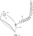
- FIG. 1 shows a painting apparatus, according to some exemplary embodiments of the subject matter.
- the painting apparatus 100 preferably comprises two bags (not shown), a paint bag, which stores paint that is used to paint a surface, and an air bag, which in operation would receive a gas, such as air, said gas will increase the size of the air bag. Since the painting apparatus has a limited ability to expand, the expansion of the air bag will result in pressure being applied to the paint bag.
- the painting apparatus 100 comprises a paint port 102, through which paint exits the painting bag.
- the paint port 102 is connected to a paint tube 103 through which paint flows from the paint port 102 to a paint accessory (not shown).
- the paint accessory distributes paint along a surface, for example a wall.
- the paint accessory is a paint roller, a paint brush, a paint spraying device, some other paint distributing apparatus, or the like.
- the paint bag of the painting apparatus 100 is preferably composed of a flexible plastic material, which enables compression of the painting apparatus 100 to force paint out of the paint bag through the paint port 102. When the paint exits the paint port 102 it flows through the paint tube 103 onto the paint accessory.
- the paint tube 103 may be disconnected from the painting apparatus 100 in order for maintenance and cleaning to enable long use of the painting apparatus 100 with different colors.
- the painting apparatus 100 preferably comprises therein an air bag (not shown) which is used for providing pressure on the paint bag, thus allowing a flow of paint from the paint bag through the paint port 102.
- an air bag (not shown) which is used for providing pressure on the paint bag, thus allowing a flow of paint from the paint bag through the paint port 102.
- it is the expansion of the air bag that causes the contraction of the paint bag and the flow of paint therefrom to the paint accessory.
- the air bag is preferably composed of an elastic material such as elastic polymer, rubber, or any other elastic material that enables the air bag to expand when gas, such as air is pumped there into. The air bag therefore acts as a balloon expanding while the air volume therein increases and applying pressure to the paint bag.
- the air bag is partially or fully attached to the paint bag, for example having a mutual sidewall or another shared surface (not shown).
- the air bag expands and applies pressure onto the paint bag. If the paint port 102 is open, paint will flow from the paint bag through the paint tube 103.
- the air bag further comprises an air port 104 through which air enters the air bag.
- the air port 104 is connected to a pumping mechanism 106, which pumps air into the air bag.
- the pumping mechanism can be mechanical, electrical, motorized, manual or the like device for pushing air into the air bag.
- the pumping mechanism 106 is mechanical and is activated by a motor (not shown).
- a unidirectional valve (not shown) is disposed onto the air port 104 or between the pumping mechanism 106 and the air port 104, to prevent the air from exiting the air bag 116.
- a sensor (not shown) is disposed between the pumping mechanism 106 and the interior side of the air bag 116, to measure the gas pressure within the air bag 116. The pumping mechanism 106 is activated when the gas sensor of the pumping mechanism 106 receives indication that the gas pressure within the air bag is below a predetermined level. In other cases, the sensor can be disposed within the pumping mechanism 106.
- the paint bag and the air bag may be of different sizes, according to the necessity of the user.
- the paint bag may have a capacity to hold at least one liter of paint.
- the air bag would have to be of a size that would enable a fully inflated air bag to substantially empty the paint bag.
- the air bag will be comprised of sufficient flexible material enabling it to expand such that most or nearly all of the paint in the paint bag can be squeezed out therefrom.
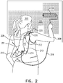
- FIG. 2 shows a user using a painting apparatus, according to some exemplary embodiments of the subject matter.
- the user 200 of the painting apparatus 210 carries the painting apparatus 210, for example, on the user's back.
- the painting apparatus can be worn with a strap on the waist or on a limb or placed next to the user 200.
- the painting apparatus 210 comprises shoulder straps 202 that the user 200 wears when carrying the painting apparatus 210.
- the user 200 holds a paint accessory 220, for example a paint roller, connected to the painting apparatus 210 in her hand 208 via a paint tube 218.
- the paint accessory 220 is pressed against a surface 204, such as a wall, to distribute paint onto the surface 204.
- a pumping mechanism 216 such as a mechanical pump having a squeezing or pressing element, is used to introduce air into the painting apparatus 210.
- the pumping action is performed when the user's presses the pumping mechanism 216, and air is pumped through air port 212 into an air bag 213.
- the air bag 213 expands applying pressure on a paint bag 211 of the painting apparatus 210.
- paint exits through a paint port 214.
- the paint flows from the paint port 214 through a paint tube 218 to the paint accessory 220.
- air bag 213 and paint bag 211 are shown and for the purpose of explanation are divided by figurative line 209, though in practice the air bag 213 and paint bag 211 will be provided within painting apparatus 210, and while air bag 213 increases in size, paint bag 211 will decrease in size as paint is pushed out therefrom through paint port 214.
- Using gas, such as air, to control the flow of paint to the paint accessory 220 enables the continuous painting with the paint accessory 220 while providing paint such that the user 200 does not have to stop painting in order to apply paint onto the paint accessory 220.
- the painting environment is cleaner and does not require carrying around heavy equipment such as paint buckets and trays, which are bulky, messy and heavy.
- the pumping mechanism 216 may employ a mechanical force.
- the pumping mechanism 216 may be a lever (not shown), which the user 200 of the painting apparatus 210 moves or pushes to pump gas into the air bag 213.
- the pumping mechanism 216 comprises a pump, such as a balloon nozzle which may be operated using the user's limb.
- gas such as air is pumped into a control tube 225 through openings (not shown), which are located on the control tube 225.
- the openings allow gas to enter the control tube 225 and to flow into the air bag 213.
- control tube 225 may be constructed so as to limit the amount of gas which is pumped into the air bag 213 so as to avoid excessive pressure applied to the paint bag 211.
- the gas entering the air bag 213 causes the air bag 213 to expand, which compresses the paint bag 211.
- the compression of the paint bag 211 causes paint to be pushed out of the paint bag 211 into the paint tube 218 towards the paint accessory 220.
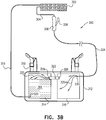
- FIG. 3A shows a schematic painting apparatus, according to some exemplary embodiments of the subject matter.
- the painting apparatus 300 comprises a paint accessory 302, which distributes paint along a surface, for example a wall.
- the paint accessory is a paint roller, paint brush, or the like.
- the paint accessory 302 is connected to a handle 306 by a connector 304.
- the handle 306 is used by a user of the painting apparatus 300 when painting an object.
- the paint accessory 302 may be disconnected from the painting apparatus 300 and replaced with a different paint accessory.
- a user of the painting apparatus 300 is using a paint roller to paint large areas on a surface and then removed the paint roller and connects a paint brush to the painting apparatus to perform finishing touches such as corners.
- the painting apparatus 300 comprises a compartment 312 that comprises a paint bag 314.
- the paint bag 314 is composed out of an elastic polymer such as elastic plastic, rubber, or any other elastic materials.
- the paint bag 314 comprises paint 318, such as acrylic paint, oil based paint, wood protective paint, or the like.
- a paint tube 310 connects the paint bag 314 to the paint accessory 302.
- the paint tube 310 is composed of a flexible polymer material. In some exemplary embodiments of the subject matter, the paint tube 310 may be disconnected from the painting apparatus 300 in order for maintenance and cleaning to enable long use of the painting apparatus 300 with different colors.
- the paint tube 310 comprises a paint tube opening 320 through which the paint 318 enters the paint tube 310 to flow to the paint accessory 302.
- the compartment 312 further comprises an air bag 316, which is used for holding a gas 325.
- the air bag 316 is composed out of an elastic polymer such as an elastic polymer, rubber, or any other elastic material that enables the air bag 316 to expand when gas 325 is pumped into the air bag 316, such that it may fully expand to provide such pressure that will force substantially all of the paint 318 from paint bag 314.
- the air bag 316 and paint bag 314 are both located within compartment 312 but are separated one from the other.
- the air bag 316 may be attached to a part or the whole or part of one or more of the walls of compartment 312.
- the paint bag 314 may be attached to a part or the whole or part of one or more of the walls of compartment 312.
- the air bag 316 is connected or partially connected to the paint bag 314, for example having a mutual portion or whole side wall or another shared surface 331. It will be understood that any attachment material can be used and any form of attachment between the bags and/or walls can be used so as to best achieve the goals of the subject matter.
- gas is pumped into the air bag, results in the air bag 316 expending and pressure is applied onto the paint bag 314.
- the paint bag 314 will then compress and decrease in size as a result and paint 318 is squeezed or forced out of the paint bag 314 through the paint tube opening 320.
- a unidirectional valve 330 is disposed in the control tube 334, preventing the gas 325 from exiting the air bag 316 after it has been pumped there into.
- the handle 306 comprises a mechanical pumping mechanism 308, which when pressed by the user of the painting apparatus 300 causes the gas 325 to be pumped into the air bag 316.
- the pumping mechanism may work mechanically.
- the mechanical pumping mechanism 308 may be a lever, which the user of the painting apparatus 300 presses to pump the gas 325 into the air bag 316.
- the pumping mechanism comprises a pump (not shown) having a balloon nozzle, which may be operated using the user's hand or foot.
- the mechanical pumping mechanism 308 is connected to the air bag 316 by a control tube 334, which pushes gas 325 into the air bag 316.
- gas 325 is pumped into the control tube 334 through openings (not shown), which are located on the control tube 334 allowing gas 325 to enter the control tube 334 and to flow into the air bag 316.
- the gas 325 entering the air bag 316 causes the air bag 316 to expand, which compresses the paint bag 314.
- the compression of the paint bag 314 causes paint to be pushed out of the paint bag 314 into the paint tube 310 towards the paint accessory 302.
- the pumping mechanism 308 is operated by a motorized pump (not shown).
- Figure 3B shows another exemplary embodiment of the painting apparatus 300, according to some exemplary embodiments of the subject matter.
- the mechanical pumping mechanism 308 pumps the gas 325 into the air bag 316, which enables the gas 325 in the air bag 316 to flow into the paint bag 314.
- the gas 325 in the air bag 316 flows through an air tube 322 into the paint bag 314.
- the gas 325 enters the air tube 322 through a first opening 326 and enters the paint bag 314 through a second opening 324.
- the pressure caused by the gas 325 entering the paint bag 314 forces paint 318 into the paint tube 310 and to the paint accessory 302.
- Figure 4 shows a person using a painting apparatus, according to some exemplary embodiments of the subject matter.
- the user 400 of the painting apparatus 402 carries the painting apparatus 402, for example, on the user's back.
- the painting apparatus 402 comprises shoulder straps 404 that the user 400 wears when carrying the painting apparatus 402.
- the user 400 holds a paint accessory 406, for example a paint roller, of the painting apparatus 402 in his hand.
- the paint accessory 406 is pressed against a surface 410, such as a wall, to distribute paint onto the surface 410.
- the user 400 holds a lever 412 in a second hand 414.
- the lever 412 is used to control the pumping action which is configured to push gas from the air bag 316 of Figure 3 into the paint bag 314 of Figure 3 .
- the air entering the paint bag pushes paint through a paint tube 416 to the paint accessory 406.
- Using air to control the flow of the paint to the paint accessory 406 enables the continuous painting with the paint accessory 406 while providing paint such that the user 400 does not have to stop painting in order put paint onto the paint accessory 406.
- the use of a control to control the pumping action can be applied to the other embodiments of the subject matter.
- Such control can be mechanical, such as a lever with a spring, electric, such a s a button to turn off an electrical pump or the like.
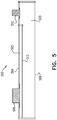
- FIG. 5 shows a side sectional and schematic view layout of a painting apparatus, according to some exemplary embodiments of the subject matter.
- the paint apparatus comprises a compartment 500 comprising a paint bag 525 and airbag 520.
- the compartment 500 comprises a paint port 506 on a top layer 504.
- the top layer 504 is a membrane of the paint bag 525 of the compartment 500.
- a bottom membrane 508 of the compartment 500 comprises an air port 510.
- the bottom membrane 508 is a portion of the airbag 520 of the compartment 500.
- a separation wall 512 separates the paint bag 525 and the airbag 520.
- the separation wall 512 may be composed of an elastic material, such as rubber, elastic polymer, plastic and the like.
- the separation wall may comprise of two layers which are connected there between in some or throughout its length.
- the airbag 520 expands applying pressure via the separation wall 512 onto the paint bag 525.
- the separation wall 512 pushes and compresses space in the paint bag 525 paint exits the paint bag through the paint port 506.
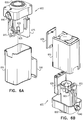
- FIGS 6A-6B show a pump device for filling an airbag of a painting apparatus, according to some exemplary embodiments of the subject matter.
- the painting apparatus 500 of Figure 5 comprises an air port 510 of Figure 5 through which air enters the air bag 520 of Figure 5 .
- the pump device 600 is connected to the air port 510, for example pump port 650 includes grooves and is applied to the air port 510 through a rotating motion as a plug.
- the pump device 600 is comprises a pump port 650, which is inserted into or connected with the air port 510 such that the pump port 650 seals the air port 510 and prevents gas from leaking out of the air port 510.
- the pump device 600 may comprise a button 630 for opening and closing a lid 610 of the pump device 600.
- the pump device 600 comprises an electrical pump 620, which pumps air into the air port 510.
- the pump device 600 comprises an energy source 625, for example batteries, which powers the electrical pump 620.
- the power source 625 may be replaceable when it runs out of power, i.e. batteries.
- the lid 610 is removed to enable access to the power source 610 to remove old batteries and insert new ones.
- the pump device 600 comprises an activation switch 640, which enables a user of the painting apparatus 500 to activate the pump device 600 when the user is painting.
- the activation switch 640 is a flip-flop switch, which turns on or off the pump device 600.
- the pump device 600 comprises a pressure control mechanism 605, which measures the gas pressure of the gas pumped through the electrical pump 620 into the air port 510.
- the pressure control mechanism 605, may be a mechanical unit which moves as the gas pressure decreases in the air bag 520, for example moving down.
- the pressure control mechanism 605 may comprise a sensor (not shown) indicating the gas pressure at the air port 510.
- the pump device 600 comprises an electric switch 615, which activates and deactivates the electrical pump 605 according to the pressure measured by the gas pressure control mechanism 620. As the pressure in the air bag 520 decreases, the pressure control mechanism 620 moves a predetermined distance to indicate a reduction of the gas pressure in the air bag 520.
- the electric switch 615 activates the electric pump 620.
- the pressure control mechanism 620 moves the predetermined distance of 10mm, which indicates that the gas pressure in the air bag 520 is lower than a predetermined pressure, such as 0.3 ppm.
- the electric switch 615 activates the electrical pump 605, causing air to flow into the air bag 520.
- the air flowing into the air bag 520 increases the gas pressure in the air bag 520 resulting in the pressure control mechanism 605 moving to a pressure control mechanism's starting location.
- the electric switch 615 deactivates the electrical pump 605, thus stopping the flow of gas through the air port 510.
- the pressure within the air bag 520 reduces when paint exits the air bag 520 allowing more space for the air bag 520 to expand thereto and hence the pressure in the air bag 520 decreases as paint exists through paint port 506 of Figure 5 .
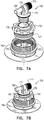
- FIG 7A shows a stopper for a paint opening of a paint apparatus, according to some exemplary embodiments of the subject matter.
- the stopper 700 is a cover of a paint port 790, which provides a convenient arrangement for attaching the paint tube 218 of Figure 2 , while sealing the paint port 790 to prevent spillage of the paint from the paint bag 525 of Figure 5 .
- the stopper 700 enables the optimal volume of the paint to exit the paint bag 505 while the painting apparatus 500 of Figure 5 is in use.
- the stopper 700 comprises an external stopper 720, which is inserted into a port 795 of the paint port 790.
- the external stopper 720 may be inserted into the port 795 the paint port 790 using a rotating motion, such as screwing the external stopper into the paint port 790.
- the external stopper comprises a stopper port 715, through which paint base is filled into the paint bag 525.
- an internal stopper 750 is inserted into the stopper port 715.
- the internal stopper 750 is molded to fit into a stopper port 715 of the external stopper 720 such that the internal stopper 750 cannot be removed from the stopper port 715, so to prevent excess spillage of paint from attempts of a user to remove the internal stopper 750.
- the internal stopper 750 is fitted into the stopper port 715 by the internal stopper 750 being pushed into the stopper port 715 such that the internal stopper 750 cannot be removed from the stopper port 715.
- the internal stopper 750 is inserted into the stopper port 715 after a paint base is poured into the paint bag 525 during production of the painting apparatus 500.
- the internal stopper 750 comprises a paint valve 770, which enables paint to flow out of the paint bag 525 into the paint tube 218.
- the paint valve 770 comprises a valve paint tube 780, which is inserted into the paint tube 218, to enable the paint to flow into the paint tube 218 without causing a leak.
- the paint tube 218 is connected to the valve paint tube 780, the paint flowing through the valve paint tube 780 flows into the paint tube 218, which flows the paint to the paint accessory 220 of Figure 2 .
- the paint valve 770 comprises a valve knob 775, which enables controlling the amount of paint that flows through the paint valve 770 into the paint tube 218.
- the valve knob 775 enables closing the paint valve 770 to enable attachment or removal of the paint tube 218 without causing spillage of the paint from the paint bag 525.
- the closing of the paint valve 770 further enables easily transporting the painting apparatus 500 without having the paint tube 218 and paint accessory 220 connected to the painting apparatus 500, and without paint leaking out of the paint bag 525.
- the external stopper 720 comprises a spiraled molding 725, such as grooves, to enable inserting the external stopper 720 into the paint port 790 though a circular motion.
- the external stopper 720 is inserted into the paint port 790 by rotating the external stopper 720 into the paint port 506 until the external stopper 720 is tightly connected to the paint port 506.
- the user purchases the painting apparatus 500, the user selects a color with which to paint.
- the paint color is then added to the paint base already in the paint bag 790.
- the stopper 700 is removable from the paint port 790 when paint color is added to the paint base already in the paint bag 525. Once the paint color is added, the stopper 700 is tightly inserted back into the paint port 506 using a rotating motion, i.e.
- the mixing is performed using a paint mixer.
- the stopper 700 is tightly inserted into the paint port 790. Once the mixing is performed, the painting apparatus 500 is prepared to be used for painting.
- Figure 7B shows the internal stopper 750 inserted into the external stopper 720, according to some exemplary embodiments of the subject matter.
- the internal stopper 750 is inserted into the external stopper 720 by applying a strong force to insert the internal stopper 750 into the external stopper port 715. It should be noted that insertion of the internal stopper 750 into the external stopper 720 occurs during production of the painting apparatus 500 after which the internal stopper 750 cannot be removed from the external stopper 720. The internal stopper 750 cannot be removed and prevents any leaking of the paint from the external port 720.
Landscapes
- Engineering & Computer Science (AREA)
- Mechanical Engineering (AREA)
- Nozzles (AREA)
Description
- The subject matter relates generally to a painting apparatus enabling even distribution of paint onto a surface.
- A paint roller is well known in the art for painting objects and structures, for example a wall of a house. The roller requires paint to be distributed along the roller to enable painting an even coat over the object that is being painted. Various apparatuses have been created to better distribute the paint on the roller from a paint bag. For example, a roller that comprises a motor that pumps paint from a paint bag. In some cases, the roller comprises a button that is used to pour the paint onto the roller through a pipe. Some painting devices enable squeezing a paint tube in which the paint is stored. The paint tube compresses causing the paint inside to flow out and onto a paint roller or paint brush. For example,
EP 0830901 describes a paint system comprising a flexible bag and a machine adapted to squeeze the bag. Paint from the bag enters a tube when the bag is squeezed by the machine. - It is an object of the subject matter to disclose a painting apparatus comprising a paint bag containing paint; a paint port through which paint flows from the paint bag; an air bag to receive gas configured to apply pressure to the paint bag as it receives air; an air port through which the gas enters the air bag. The painting apparatus further comprises a compartment, the compartment comprising the paint bag and the airbag. A separation wall separates the paint bag and the airbag, said separation wall being composed of an elastic material. The compartment comprises the paint port on a top layer, wherein the top layer is a membrane of the paint bag of the compartment. The compartment comprises a bottom membrane that comprises the air port and is a portion of the airbag of the compartment. As gas enters the air port, the air bag expands, applying pressure via the separation wall onto the paint bag and wherein as the separation wall pushes and compresses space in the paint bag, paint exits the paint bag through the paint port.
- In some cases, the painting apparatus further comprises a paint tube to convey paint from the paint port to a paint accessory that distributes the paint onto a surface.
- In some cases, the painting apparatus further comprises a paint accessory to distribute paint onto a surface.
- In some cases, the painting apparatus further comprises a pressure valve connected to the air port, wherein the unidirectional valve is opened or closed depending on the pressure of the gas within the air bag.
- In some cases, the painting apparatus further comprises a mechanical pump having a pressing element, said mechanical pump is used to introduce air into the air bag.
- In some cases, the painting apparatus further comprise a pump device connected to the air port to introduce air into the air bag, said pump device comprises: a pump for pumping the gas via the air port into the air bag; an electric switch to activate and deactivate the pump; an energy source; a pressure control mechanism that moves according to gas pressure in the air bag; wherein the electric switch activates the pump when the pressure control mechanism moves a predetermined distance.
- In some cases, the electric switch is activated at predetermined time increments.
- In some cases, the pump device comprises an activation switch to enable activation of the pump device.
- In some cases, the electric switch deactivates the pump when the pressure control mechanism is at a pressure control mechanism original location.
In some cases, the painting apparatus further comprises a shoulder straps for carrying the paint apparatus. - Exemplary non-limited embodiments of the disclosed subject matter will be described, with reference to the following description of the embodiments, in conjunction with the figures. The figures are generally not shown to scale and any sizes are only meant to be exemplary and not necessarily limiting. Corresponding or like elements are optionally designated by the same numerals or letters. The embodiments shown in
Figures 1 to 4 and6A to 7B are provided as illustrative, non-claimed examples only. -
Figure 1 shows a painting apparatus, according to some exemplary embodiments of the subject matter; -
Figure 2 shows a user using a painting apparatus, according to some exemplary embodiments of the subject matter; -
Figure 3A-3B show a painting apparatus, according to some exemplary embodiments of the subject matter; -
Figure 4 shows a person using a painting apparatus, according to some exemplary embodiments of the subject matter; -
Figure 5 shows a side view schematic layout of a painting apparatus, according to some exemplary embodiments of the subject matter; -
Figures 6A-6B show a mechanical pump for filling an airbag of a painting apparatus, according to some exemplary embodiments of the subject matter; and, -
Figures 7A-7B show a stopper for a paint opening of a painting apparatus, according to some exemplary embodiments of the subject matter. - The subject matter relates generally to a painting apparatus enabling distribution of paint onto a surface, according to exemplary embodiments.
- One technical problem dealt by the disclosed subject matter is providing a paint accessory, such as a paint roller with paint, without the need to dip the paint roller into a paint source, such as a paint bucket, while painting a surface. Another technical problem dealt with the disclosed subject matter is providing a paint accessory with continuous paint flow from a paint source. Yet another technical problem dealt with the disclosed subject matter is providing a paint source that can provide paint to a paint accessory on demand.
- One technical solution according to the disclosed subject matter is a painting apparatus, which comprises the paint accessory connected to the painting apparatus. The painting apparatus comprises a paint bag having a tube attached thereto, to convey the paint from the paint bag to the paint accessory. The painting apparatus also comprises an air bag attached or connected to the paint bag, such that when air is delivered into the air bag the expansion of the air bag results in pressure onto the paint bag, forcing paint to exit the paint bag through a paint tube, the paint flows towards the paint accessory. A user of the painting apparatus controls an air pump to pump air into the air bag. Alternatively, air or another gas is pumped into the paint bag automatically.
-
Figure 1 shows a painting apparatus, according to some exemplary embodiments of the subject matter. Thepainting apparatus 100 preferably comprises two bags (not shown), a paint bag, which stores paint that is used to paint a surface, and an air bag, which in operation would receive a gas, such as air, said gas will increase the size of the air bag. Since the painting apparatus has a limited ability to expand, the expansion of the air bag will result in pressure being applied to the paint bag. Thepainting apparatus 100 comprises apaint port 102, through which paint exits the painting bag. In accordance with some embodiments of the subject matter, thepaint port 102 is connected to apaint tube 103 through which paint flows from thepaint port 102 to a paint accessory (not shown). The paint accessory distributes paint along a surface, for example a wall. In some exemplary embodiments of the subject matter, the paint accessory is a paint roller, a paint brush, a paint spraying device, some other paint distributing apparatus, or the like. The paint bag of thepainting apparatus 100 is preferably composed of a flexible plastic material, which enables compression of thepainting apparatus 100 to force paint out of the paint bag through thepaint port 102. When the paint exits thepaint port 102 it flows through thepaint tube 103 onto the paint accessory. In some exemplary embodiments of the subject matter, thepaint tube 103 may be disconnected from thepainting apparatus 100 in order for maintenance and cleaning to enable long use of thepainting apparatus 100 with different colors. - The
painting apparatus 100 preferably comprises therein an air bag (not shown) which is used for providing pressure on the paint bag, thus allowing a flow of paint from the paint bag through thepaint port 102. According to this embodiment, it is the expansion of the air bag that causes the contraction of the paint bag and the flow of paint therefrom to the paint accessory. Person skilled in the art will appreciate that any other mechanism, which can apply contraction force on the paint bag can be used in the alternative to drive the paint out of the paint bag. The air bag is preferably composed of an elastic material such as elastic polymer, rubber, or any other elastic material that enables the air bag to expand when gas, such as air is pumped there into. The air bag therefore acts as a balloon expanding while the air volume therein increases and applying pressure to the paint bag. The air bag is partially or fully attached to the paint bag, for example having a mutual sidewall or another shared surface (not shown). When air is pumped into the air bag, the air bag expands and applies pressure onto the paint bag. If thepaint port 102 is open, paint will flow from the paint bag through thepaint tube 103. The air bag further comprises anair port 104 through which air enters the air bag. In some exemplary embodiments of the subject matter, theair port 104 is connected to apumping mechanism 106, which pumps air into the air bag. The pumping mechanism can be mechanical, electrical, motorized, manual or the like device for pushing air into the air bag. In some exemplary embodiments, thepumping mechanism 106 is mechanical and is activated by a motor (not shown). In some cases, a unidirectional valve (not shown) is disposed onto theair port 104 or between thepumping mechanism 106 and theair port 104, to prevent the air from exiting the air bag 116. In some cases, a sensor (not shown) is disposed between thepumping mechanism 106 and the interior side of the air bag 116, to measure the gas pressure within the air bag 116. Thepumping mechanism 106 is activated when the gas sensor of thepumping mechanism 106 receives indication that the gas pressure within the air bag is below a predetermined level. In other cases, the sensor can be disposed within thepumping mechanism 106. - The paint bag and the air bag may be of different sizes, according to the necessity of the user. For example, where the user of the
painting apparatus 100 is painting a wall of a house, the paint bag may have a capacity to hold at least one liter of paint. The air bag would have to be of a size that would enable a fully inflated air bag to substantially empty the paint bag. According to such embodiment, the air bag will be comprised of sufficient flexible material enabling it to expand such that most or nearly all of the paint in the paint bag can be squeezed out therefrom. -
Figure 2 shows a user using a painting apparatus, according to some exemplary embodiments of the subject matter. Theuser 200 of thepainting apparatus 210 carries thepainting apparatus 210, for example, on the user's back. In other embodiments of the subject matter, the painting apparatus can be worn with a strap on the waist or on a limb or placed next to theuser 200. Thepainting apparatus 210 comprises shoulder straps 202 that theuser 200 wears when carrying thepainting apparatus 210. Theuser 200 holds apaint accessory 220, for example a paint roller, connected to thepainting apparatus 210 in herhand 208 via apaint tube 218. Thepaint accessory 220 is pressed against asurface 204, such as a wall, to distribute paint onto thesurface 204. As seen inFigure 2 , apumping mechanism 216, such as a mechanical pump having a squeezing or pressing element, is used to introduce air into thepainting apparatus 210. In action, the pumping action is performed when the user's presses thepumping mechanism 216, and air is pumped throughair port 212 into anair bag 213. As the air enters theair bag 213, theair bag 213 expands applying pressure on apaint bag 211 of thepainting apparatus 210. As thepaint bag 211 is compressed by the expansion of theair bag 213 paint exits through apaint port 214. The paint flows from thepaint port 214 through apaint tube 218 to thepaint accessory 220. In the presentfigure 2 ,air bag 213 andpaint bag 211 are shown and for the purpose of explanation are divided byfigurative line 209, though in practice theair bag 213 andpaint bag 211 will be provided withinpainting apparatus 210, and whileair bag 213 increases in size,paint bag 211 will decrease in size as paint is pushed out therefrom throughpaint port 214. - Using gas, such as air, to control the flow of paint to the
paint accessory 220 enables the continuous painting with thepaint accessory 220 while providing paint such that theuser 200 does not have to stop painting in order to apply paint onto thepaint accessory 220. The painting environment is cleaner and does not require carrying around heavy equipment such as paint buckets and trays, which are bulky, messy and heavy. - In some exemplary embodiments of the subject matter, the
pumping mechanism 216 may employ a mechanical force. In some other cases, thepumping mechanism 216 may be a lever (not shown), which theuser 200 of thepainting apparatus 210 moves or pushes to pump gas into theair bag 213. In some exemplary cases, thepumping mechanism 216 comprises a pump, such as a balloon nozzle which may be operated using the user's limb. When thepumping mechanism 216 is pressed or squeezed, gas, such as air is pumped into acontrol tube 225 through openings (not shown), which are located on thecontrol tube 225. When thepumping mechanism 216 is pressed, the openings allow gas to enter thecontrol tube 225 and to flow into theair bag 213. In some other embodiments of the present subject matter thecontrol tube 225 may be constructed so as to limit the amount of gas which is pumped into theair bag 213 so as to avoid excessive pressure applied to thepaint bag 211. The gas entering theair bag 213 causes theair bag 213 to expand, which compresses thepaint bag 211. The compression of thepaint bag 211 causes paint to be pushed out of thepaint bag 211 into thepaint tube 218 towards thepaint accessory 220. -
Figure 3A shows a schematic painting apparatus, according to some exemplary embodiments of the subject matter. Thepainting apparatus 300 comprises apaint accessory 302, which distributes paint along a surface, for example a wall. For example, the paint accessory is a paint roller, paint brush, or the like. Thepaint accessory 302 is connected to ahandle 306 by aconnector 304. Thehandle 306 is used by a user of thepainting apparatus 300 when painting an object. In some cases, thepaint accessory 302 may be disconnected from thepainting apparatus 300 and replaced with a different paint accessory. For example, a user of thepainting apparatus 300 is using a paint roller to paint large areas on a surface and then removed the paint roller and connects a paint brush to the painting apparatus to perform finishing touches such as corners. Thepainting apparatus 300 comprises acompartment 312 that comprises apaint bag 314. Thepaint bag 314 is composed out of an elastic polymer such as elastic plastic, rubber, or any other elastic materials. Thepaint bag 314 comprisespaint 318, such as acrylic paint, oil based paint, wood protective paint, or the like. Apaint tube 310 connects thepaint bag 314 to thepaint accessory 302. Thepaint tube 310 is composed of a flexible polymer material. In some exemplary embodiments of the subject matter, thepaint tube 310 may be disconnected from thepainting apparatus 300 in order for maintenance and cleaning to enable long use of thepainting apparatus 300 with different colors. Thepaint tube 310 comprises apaint tube opening 320 through which thepaint 318 enters thepaint tube 310 to flow to thepaint accessory 302. Thecompartment 312 further comprises anair bag 316, which is used for holding agas 325. Theair bag 316 is composed out of an elastic polymer such as an elastic polymer, rubber, or any other elastic material that enables theair bag 316 to expand whengas 325 is pumped into theair bag 316, such that it may fully expand to provide such pressure that will force substantially all of thepaint 318 frompaint bag 314. In some embodiments of the subject matter, theair bag 316 andpaint bag 314 are both located withincompartment 312 but are separated one from the other. In some other embodiments of the subject matter theair bag 316 may be attached to a part or the whole or part of one or more of the walls ofcompartment 312. In some embodiments of the subject matter thepaint bag 314 may be attached to a part or the whole or part of one or more of the walls ofcompartment 312. In other embodiments of the subject matter, theair bag 316 is connected or partially connected to thepaint bag 314, for example having a mutual portion or whole side wall or another sharedsurface 331. It will be understood that any attachment material can be used and any form of attachment between the bags and/or walls can be used so as to best achieve the goals of the subject matter. When gas is pumped into the air bag, results in theair bag 316 expending and pressure is applied onto thepaint bag 314. Thepaint bag 314 will then compress and decrease in size as a result and paint 318 is squeezed or forced out of thepaint bag 314 through thepaint tube opening 320. In some cases, aunidirectional valve 330 is disposed in thecontrol tube 334, preventing thegas 325 from exiting theair bag 316 after it has been pumped there into. - In some cases, the
handle 306 comprises amechanical pumping mechanism 308, which when pressed by the user of thepainting apparatus 300 causes thegas 325 to be pumped into theair bag 316. The pumping mechanism may work mechanically. In some other cases, themechanical pumping mechanism 308 may be a lever, which the user of thepainting apparatus 300 presses to pump thegas 325 into theair bag 316. In yet other exemplary cases, the pumping mechanism comprises a pump (not shown) having a balloon nozzle, which may be operated using the user's hand or foot. Themechanical pumping mechanism 308 is connected to theair bag 316 by acontrol tube 334, which pushesgas 325 into theair bag 316. When thepumping mechanism 308 is pressed,gas 325 is pumped into thecontrol tube 334 through openings (not shown), which are located on thecontrol tube 334 allowinggas 325 to enter thecontrol tube 334 and to flow into theair bag 316. Thegas 325 entering theair bag 316 causes theair bag 316 to expand, which compresses thepaint bag 314. The compression of thepaint bag 314 causes paint to be pushed out of thepaint bag 314 into thepaint tube 310 towards thepaint accessory 302. As is further described in connection with other embodiments of the subject matter, in yet other embodiments, thepumping mechanism 308 is operated by a motorized pump (not shown). -
Figure 3B shows another exemplary embodiment of thepainting apparatus 300, according to some exemplary embodiments of the subject matter. Themechanical pumping mechanism 308 pumps thegas 325 into theair bag 316, which enables thegas 325 in theair bag 316 to flow into thepaint bag 314. Thegas 325 in theair bag 316 flows through anair tube 322 into thepaint bag 314. Thegas 325 enters theair tube 322 through afirst opening 326 and enters thepaint bag 314 through asecond opening 324. The pressure caused by thegas 325 entering thepaint bag 314 forces paint 318 into thepaint tube 310 and to thepaint accessory 302. -
Figure 4 shows a person using a painting apparatus, according to some exemplary embodiments of the subject matter. Theuser 400 of thepainting apparatus 402 carries thepainting apparatus 402, for example, on the user's back. Thepainting apparatus 402 comprisesshoulder straps 404 that theuser 400 wears when carrying thepainting apparatus 402. Theuser 400 holds apaint accessory 406, for example a paint roller, of thepainting apparatus 402 in his hand. Thepaint accessory 406 is pressed against asurface 410, such as a wall, to distribute paint onto thesurface 410. In some exemplary embodiments of the subject matter, theuser 400 holds alever 412 in asecond hand 414. Thelever 412 is used to control the pumping action which is configured to push gas from theair bag 316 ofFigure 3 into thepaint bag 314 ofFigure 3 . The air entering the paint bag pushes paint through apaint tube 416 to the paint accessory 406.Using air to control the flow of the paint to thepaint accessory 406 enables the continuous painting with thepaint accessory 406 while providing paint such that theuser 400 does not have to stop painting in order put paint onto thepaint accessory 406. The use of a control to control the pumping action can be applied to the other embodiments of the subject matter. Such control can be mechanical, such as a lever with a spring, electric, such a s a button to turn off an electrical pump or the like. -
Figure 5 shows a side sectional and schematic view layout of a painting apparatus, according to some exemplary embodiments of the subject matter. The paint apparatus comprises acompartment 500 comprising apaint bag 525 andairbag 520. Thecompartment 500 comprises apaint port 506 on atop layer 504. Thetop layer 504 is a membrane of thepaint bag 525 of thecompartment 500. Abottom membrane 508 of thecompartment 500 comprises anair port 510. Thebottom membrane 508 is a portion of theairbag 520 of thecompartment 500. Aseparation wall 512 separates thepaint bag 525 and theairbag 520. Theseparation wall 512 may be composed of an elastic material, such as rubber, elastic polymer, plastic and the like. In some embodiments of the subject matter, the separation wall may comprise of two layers which are connected there between in some or throughout its length. As gas enters theair port 510, theairbag 520 expands applying pressure via theseparation wall 512 onto thepaint bag 525. As theseparation wall 512 pushes and compresses space in thepaint bag 525 paint exits the paint bag through thepaint port 506. -
Figures 6A-6B show a pump device for filling an airbag of a painting apparatus, according to some exemplary embodiments of the subject matter. Thepainting apparatus 500 ofFigure 5 comprises anair port 510 ofFigure 5 through which air enters theair bag 520 ofFigure 5 . Thepump device 600 is connected to theair port 510, forexample pump port 650 includes grooves and is applied to theair port 510 through a rotating motion as a plug. Thepump device 600 is comprises apump port 650, which is inserted into or connected with theair port 510 such that thepump port 650 seals theair port 510 and prevents gas from leaking out of theair port 510. Thepump device 600 may comprise abutton 630 for opening and closing alid 610 of thepump device 600. Thepump device 600 comprises anelectrical pump 620, which pumps air into theair port 510. Thepump device 600 comprises anenergy source 625, for example batteries, which powers theelectrical pump 620. Thepower source 625 may be replaceable when it runs out of power, i.e. batteries. When the power source must be replaced, thelid 610 is removed to enable access to thepower source 610 to remove old batteries and insert new ones. Thepump device 600 comprises anactivation switch 640, which enables a user of thepainting apparatus 500 to activate thepump device 600 when the user is painting. In some cases, theactivation switch 640 is a flip-flop switch, which turns on or off thepump device 600. Thepump device 600 comprises apressure control mechanism 605, which measures the gas pressure of the gas pumped through theelectrical pump 620 into theair port 510. Thepressure control mechanism 605, may be a mechanical unit which moves as the gas pressure decreases in theair bag 520, for example moving down. In some non-limiting cases, thepressure control mechanism 605 may comprise a sensor (not shown) indicating the gas pressure at theair port 510. Thepump device 600 comprises anelectric switch 615, which activates and deactivates theelectrical pump 605 according to the pressure measured by the gaspressure control mechanism 620. As the pressure in theair bag 520 decreases, thepressure control mechanism 620 moves a predetermined distance to indicate a reduction of the gas pressure in theair bag 520. When the pressure control mechanism reaches 620 moves a predetermined distance, theelectric switch 615 activates theelectric pump 620. For example, thepressure control mechanism 620 moves the predetermined distance of 10mm, which indicates that the gas pressure in theair bag 520 is lower than a predetermined pressure, such as 0.3 ppm. Theelectric switch 615 activates theelectrical pump 605, causing air to flow into theair bag 520. The air flowing into theair bag 520 increases the gas pressure in theair bag 520 resulting in thepressure control mechanism 605 moving to a pressure control mechanism's starting location. When thepressure control mechanism 620 reaches the pressure control mechanism's starting location, theelectric switch 615 deactivates theelectrical pump 605, thus stopping the flow of gas through theair port 510. The pressure within theair bag 520 reduces when paint exits theair bag 520 allowing more space for theair bag 520 to expand thereto and hence the pressure in theair bag 520 decreases as paint exists throughpaint port 506 ofFigure 5 . -
Figure 7A shows a stopper for a paint opening of a paint apparatus, according to some exemplary embodiments of the subject matter. Thestopper 700 is a cover of apaint port 790, which provides a convenient arrangement for attaching thepaint tube 218 ofFigure 2 , while sealing thepaint port 790 to prevent spillage of the paint from thepaint bag 525 ofFigure 5 . Thestopper 700 enables the optimal volume of the paint to exit the paint bag 505 while thepainting apparatus 500 ofFigure 5 is in use. Thestopper 700 comprises anexternal stopper 720, which is inserted into aport 795 of thepaint port 790. Theexternal stopper 720 may be inserted into theport 795 thepaint port 790 using a rotating motion, such as screwing the external stopper into thepaint port 790. The external stopper comprises astopper port 715, through which paint base is filled into thepaint bag 525. After the paint bag is filled with the paint base, aninternal stopper 750 is inserted into thestopper port 715. Theinternal stopper 750 is molded to fit into astopper port 715 of theexternal stopper 720 such that theinternal stopper 750 cannot be removed from thestopper port 715, so to prevent excess spillage of paint from attempts of a user to remove theinternal stopper 750. Theinternal stopper 750 is fitted into thestopper port 715 by theinternal stopper 750 being pushed into thestopper port 715 such that theinternal stopper 750 cannot be removed from thestopper port 715. Theinternal stopper 750 is inserted into thestopper port 715 after a paint base is poured into thepaint bag 525 during production of thepainting apparatus 500. - The
internal stopper 750 comprises apaint valve 770, which enables paint to flow out of thepaint bag 525 into thepaint tube 218. Thepaint valve 770 comprises avalve paint tube 780, which is inserted into thepaint tube 218, to enable the paint to flow into thepaint tube 218 without causing a leak. When thepaint tube 218 is connected to thevalve paint tube 780, the paint flowing through thevalve paint tube 780 flows into thepaint tube 218, which flows the paint to thepaint accessory 220 ofFigure 2 . Thepaint valve 770 comprises avalve knob 775, which enables controlling the amount of paint that flows through thepaint valve 770 into thepaint tube 218. Thevalve knob 775 enables closing thepaint valve 770 to enable attachment or removal of thepaint tube 218 without causing spillage of the paint from thepaint bag 525. The closing of thepaint valve 770 further enables easily transporting thepainting apparatus 500 without having thepaint tube 218 and paintaccessory 220 connected to thepainting apparatus 500, and without paint leaking out of thepaint bag 525. - The
external stopper 720 comprises a spiraledmolding 725, such as grooves, to enable inserting theexternal stopper 720 into thepaint port 790 though a circular motion. Theexternal stopper 720 is inserted into thepaint port 790 by rotating theexternal stopper 720 into thepaint port 506 until theexternal stopper 720 is tightly connected to thepaint port 506. When the user purchases thepainting apparatus 500, the user selects a color with which to paint. The paint color is then added to the paint base already in thepaint bag 790. Thestopper 700 is removable from thepaint port 790 when paint color is added to the paint base already in thepaint bag 525. Once the paint color is added, thestopper 700 is tightly inserted back into thepaint port 506 using a rotating motion, i.e. twisting motion, to enable mixing the contents of thepaint bag 525 to make the paint ready for use. The mixing is performed using a paint mixer. To prevent paint from spilling from thepaint bag 525, thestopper 700 is tightly inserted into thepaint port 790. Once the mixing is performed, thepainting apparatus 500 is prepared to be used for painting. -
Figure 7B shows theinternal stopper 750 inserted into theexternal stopper 720, according to some exemplary embodiments of the subject matter. Theinternal stopper 750 is inserted into theexternal stopper 720 by applying a strong force to insert theinternal stopper 750 into theexternal stopper port 715. It should be noted that insertion of theinternal stopper 750 into theexternal stopper 720 occurs during production of thepainting apparatus 500 after which theinternal stopper 750 cannot be removed from theexternal stopper 720. Theinternal stopper 750 cannot be removed and prevents any leaking of the paint from theexternal port 720. - While the disclosure has been described with reference to exemplary embodiments, it will be understood by those skilled in the art that various changes may be made and equivalents may be substituted for elements thereof without departing from the scope of the subject matter. In addition, many modifications may be made to adapt a particular situation or material to the teachings without departing from the essential scope thereof. Therefore, it is intended that the disclosed subject matter not be limited to the particular embodiment disclosed as the best mode contemplated for carrying out this subject matter, but only by the claims that follow.
Claims (10)
- A painting apparatus comprising:a paint bag (525) containing paint;a paint port (506) through which paint flows from the paint bag (525);an air bag (520) to receive gas configured to apply pressure to the paint bag (525) as it receives air;an air port (510) through which the gas enters the air bag (520);wherein the paint apparatus comprises a compartment (500) comprising:said paint bag (525); andsaid airbag (520);characterized in that said compartment (500) comprises said paint port (506) on a top layer (504), wherein said top layer (504) is a membrane of the paint bag (525) of said compartment (500);wherein a bottom membrane (508) of said compartment (500) comprises said air port (510), said bottom membrane (508) being a portion of said airbag (520) of said compartment (500);wherein a separation wall (512) separates the paint bag (525) and the airbag (520), said separation wall (512) being composed of an elastic material;wherein as gas enters said air port (510), said airbag (520) expands applying pressure via the separation wall (512) onto the paint bag (525); andwherein, as the separation wall (512) pushes and compresses space in the paint bag (525), paint exits the paint bag (525) through the paint port (506).
- The paint apparatus of claim 1, further comprising a paint tube (103) to convey paint from the paint port (506) to a paint accessory (220) that distributes the paint onto a surface (204).
- The paint apparatus of claim 1, further comprising a paint accessory (220) to distribute paint onto a surface (204).
- The paint apparatus of claim 1, further comprising a pressure valve connected to the air port (510), wherein the unidirectional valve is opened or closed depending on the pressure of the gas within the air bag (520).
- The paint apparatus of claim 1, further comprising a mechanical pump having a pressing element, said mechanical pump is used to introduce air into the air bag.
- The paint apparatus of claim 1, further comprising a pump device (600) connected to the air port (510) to introduce air into the air bag (520), said pump device (600) comprises:an electric pump (620) for pumping the gas via the air port (510) into the air bag (520);an electric switch (615) to activate and deactivate the pump (620);an energy source (625);a pressure control mechanism (605) that moves according to gas pressure in the air bag (520);wherein the electric switch (615) activates the pump (620) when the pressure control mechanism (605) moves a predetermined distance.
- The paint apparatus of claim 6, wherein the electric switch (615) is activated at predetermined time increments.
- The paint apparatus of claim 6, wherein the pump device (600) comprises an activation switch to enable activation of the pump device (600).
- The paint apparatus of claim 6, wherein the electric switch (615) deactivates the pump when the pressure control mechanism (605) is at a pressure control mechanism original location.
- The paint apparatus of claim 1, further comprising shoulder straps (404) for carrying the paint apparatus.
Applications Claiming Priority (1)
| Application Number | Priority Date | Filing Date | Title |
|---|---|---|---|
| US14/558,759 US9475084B2 (en) | 2014-12-03 | 2014-12-03 | Painting apparatus comprising an air bag |
Publications (2)
| Publication Number | Publication Date |
|---|---|
| EP3028768A1 EP3028768A1 (en) | 2016-06-08 |
| EP3028768B1 true EP3028768B1 (en) | 2019-06-19 |
Family
ID=52349923
Family Applications (2)
| Application Number | Title | Priority Date | Filing Date |
|---|---|---|---|
| EP14197483.2A Not-in-force EP3028768B1 (en) | 2014-12-03 | 2014-12-11 | A painting apparatus comprising an air bag |
| EP15197888.9A Withdrawn EP3028769A1 (en) | 2014-12-03 | 2015-12-03 | A painting apparatus comprising an air bag |
Family Applications After (1)
| Application Number | Title | Priority Date | Filing Date |
|---|---|---|---|
| EP15197888.9A Withdrawn EP3028769A1 (en) | 2014-12-03 | 2015-12-03 | A painting apparatus comprising an air bag |
Country Status (4)
| Country | Link |
|---|---|
| US (1) | US9475084B2 (en) |
| EP (2) | EP3028768B1 (en) |
| HK (2) | HK1226692A1 (en) |
| IL (2) | IL236119A (en) |
Families Citing this family (7)
| Publication number | Priority date | Publication date | Assignee | Title |
|---|---|---|---|---|
| JP6243449B2 (en) * | 2013-12-18 | 2017-12-06 | 富士機械製造株式会社 | Solder supply device |
| WO2020049386A1 (en) * | 2018-09-04 | 2020-03-12 | Oneg Hakarmel Ltd | Disinfectant applicator device with contoured roller |
| US20210308715A1 (en) * | 2020-04-04 | 2021-10-07 | Uvaldo Vera Martin | Paint roller system |
| CN112024214B (en) * | 2020-08-24 | 2021-08-17 | 西南石油大学 | Corrosion inhibitor spray coating device for gathering and transportation pipeline and operation method thereof |
| CN114472120B (en) * | 2022-02-25 | 2023-01-24 | 华博管业有限公司 | Inner wall anticorrosion process suitable for stainless steel elbow pipe fitting |
| CN114863697A (en) * | 2022-04-11 | 2022-08-05 | 丁秀秀 | A mobile monitoring system for highway road conditions |
| GB2624876A (en) * | 2022-11-29 | 2024-06-05 | Medmix Switzerland Ag | Dispenser with spray applicator |
Family Cites Families (24)
| Publication number | Priority date | Publication date | Assignee | Title |
|---|---|---|---|---|
| US141522A (en) | 1873-08-05 | Self and louis vasaly | ||
| US2882542A (en) | 1955-07-11 | 1959-04-21 | Warren W Martin | Roller-type paint applicator |
| US2932043A (en) | 1956-03-01 | 1960-04-12 | Edward S Bischoff | Liquid coating applicator |
| US3070825A (en) | 1960-02-12 | 1963-01-01 | Robert G Martin | Fountain paint applicator |
| US3304573A (en) | 1963-11-26 | 1967-02-21 | Stephen F Stefely | Liquid coating equipment |
| CH480198A (en) | 1967-11-30 | 1969-10-31 | Technovalor | Applicator for liquids, in particular paints |
| GB1262552A (en) | 1969-11-20 | 1972-02-02 | Ass Sprayers Ltd | A hand-operable painting appliance |
| US3933415A (en) * | 1973-05-11 | 1976-01-20 | Woolpert John C | Painting system |
| US3960294A (en) | 1975-06-18 | 1976-06-01 | Bernard Rodolphe J | Viscous material dispenser |
| US4328843A (en) | 1978-02-27 | 1982-05-11 | Minoru Fujii | Pressurized dispensers for dispensing products utilizing a pressure transfer fluid |
| US5935659A (en) * | 1996-01-11 | 1999-08-10 | Imperial Chemical Industries Plc | Process and apparatus for the roller-application of an aqueous thixotropic coating composition |
| GB2309183B (en) | 1996-09-07 | 1997-12-10 | Black & Decker Inc | Paint system applicator |
| GB2309266B (en) | 1996-09-07 | 1997-12-17 | Black & Decker Inc | Paint system interlock |
| GB2309493B (en) | 1996-09-07 | 1998-01-14 | Black & Decker Inc | Pump unit(paint system) |
| US5797520A (en) * | 1996-09-24 | 1998-08-25 | Northrop Grumman Corporation | Metering system and method for use with fluids having a high solid content |
| US6206599B1 (en) | 2000-06-26 | 2001-03-27 | Franklyn Buchanan | Paint roller handle construction having a self contained paint supply |
| GB2380149A (en) | 2001-09-26 | 2003-04-02 | Leslie Taggart | Handheld liquid applicator |
| US6712238B1 (en) * | 2002-10-08 | 2004-03-30 | Spraytex, Inc. | Drywall taping and texture system using bladder pump with pneumatic flip/flop logic remote control |
| CA2411969A1 (en) | 2002-11-18 | 2003-03-13 | Gregory A. Coombs | Method of fluid application and applicator assembly thereof |
| US7556447B2 (en) | 2005-07-25 | 2009-07-07 | Diversified Dynamics Corporation | Metered twist paint stick |
| US20120224909A1 (en) | 2008-02-28 | 2012-09-06 | Carlos Saravia Castillon | Mechanism for eficiently supplying paint to a roller or brush |
| ES1069234Y (en) * | 2008-12-04 | 2009-05-28 | Moreno Carlos Gomez | PAINTING ROLLER WITH CONTINUOUS FEED |
| DE202009013502U1 (en) * | 2009-09-29 | 2009-12-24 | Huber Packaging Group Gmbh + Co. Kg | Application device for dispensing liquid, pasty or granular media |
| US20140203039A1 (en) | 2011-09-26 | 2014-07-24 | Dispensing Technologies B.V. | SYSTEMS AND METHODS FOR DISPENSING ONE OR MORE LIQUIDS FROM A PORTABLE SELF-CONTAINED APPARATUS ("Industrial Flair") |
-
2014
- 2014-12-03 US US14/558,759 patent/US9475084B2/en not_active Expired - Fee Related
- 2014-12-07 IL IL236119A patent/IL236119A/en not_active IP Right Cessation
- 2014-12-11 EP EP14197483.2A patent/EP3028768B1/en not_active Not-in-force
-
2015
- 2015-12-03 EP EP15197888.9A patent/EP3028769A1/en not_active Withdrawn
- 2015-12-03 IL IL242922A patent/IL242922A0/en unknown
-
2016
- 2016-12-06 HK HK16113888.0A patent/HK1226692A1/en unknown
- 2016-12-06 HK HK16113889.9A patent/HK1226693A1/en unknown
Non-Patent Citations (1)
| Title |
|---|
| None * |
Also Published As
| Publication number | Publication date |
|---|---|
| US20160158792A1 (en) | 2016-06-09 |
| HK1226692A1 (en) | 2017-10-06 |
| US9475084B2 (en) | 2016-10-25 |
| IL236119A (en) | 2017-11-30 |
| IL242922A0 (en) | 2016-04-21 |
| EP3028769A1 (en) | 2016-06-08 |
| EP3028768A1 (en) | 2016-06-08 |
| HK1226693A1 (en) | 2017-10-06 |
Similar Documents
| Publication | Publication Date | Title |
|---|---|---|
| US9475084B2 (en) | Painting apparatus comprising an air bag | |
| US5913456A (en) | Pressurized portable drinking system | |
| TW453861B (en) | Liquid dispenser and distribution apparatus for washing structures, and methods | |
| PL2430955T3 (en) | A substance dispensing system | |
| JP2005199053A5 (en) | ||
| US20070235471A1 (en) | Back pack applicator for coatings or sealants | |
| US5411183A (en) | Liquid spray or foam dispensing apparatus | |
| KR101155400B1 (en) | Content discharge pressurization type of package | |
| US20070194052A1 (en) | Ergonomic fluid dispenser | |
| US10112211B2 (en) | Painting apparatus comprising an air bag | |
| US10065204B2 (en) | Dual flow disperser | |
| US20150266189A1 (en) | Liquid-dispensing razor | |
| US9486063B2 (en) | Paint application assembly | |
| US8353430B2 (en) | Pressurized dispensable container operable in any orientation | |
| US20180193854A1 (en) | Pressure Producing Device With A Portable Power Source | |
| JP2011098777A (en) | Jet tube container for foamy substance | |
| CN106836750B (en) | It is installed on the cock of coating machine | |
| KR20160145887A (en) | Puff having a lid of the dual grib and with outlet pump | |
| KR20150141325A (en) | An Automatic supplying device of a paint for portable | |
| KR20150121631A (en) | Automatic pneumatic conveying sprayer | |
| KR101992025B1 (en) | Paint spray device | |
| US20220015599A1 (en) | Resevoir mop and related method | |
| KR101838391B1 (en) | Filling apparatus, cosmetic vessel, cosmetic filling set and method of cosmetic filling | |
| US588545A (en) | Chusetts | |
| KR102322665B1 (en) | Filling apparatus, cosmetic vessel, cosmetic filling set and method of cosmetic filling |
Legal Events
| Date | Code | Title | Description |
|---|---|---|---|
| PUAI | Public reference made under article 153(3) epc to a published international application that has entered the european phase |
Free format text: ORIGINAL CODE: 0009012 |
|
| AK | Designated contracting states |
Kind code of ref document: A1 Designated state(s): AL AT BE BG CH CY CZ DE DK EE ES FI FR GB GR HR HU IE IS IT LI LT LU LV MC MK MT NL NO PL PT RO RS SE SI SK SM TR |
|
| AX | Request for extension of the european patent |
Extension state: BA ME |
|
| 17P | Request for examination filed |
Effective date: 20160727 |
|
| RBV | Designated contracting states (corrected) |
Designated state(s): AL AT BE BG CH CY CZ DE DK EE ES FI FR GB GR HR HU IE IS IT LI LT LU LV MC MK MT NL NO PL PT RO RS SE SI SK SM TR |
|
| STAA | Information on the status of an ep patent application or granted ep patent |
Free format text: STATUS: EXAMINATION IS IN PROGRESS |
|
| 17Q | First examination report despatched |
Effective date: 20170531 |
|
| REG | Reference to a national code |
Ref country code: HK Ref legal event code: DE Ref document number: 1226692 Country of ref document: HK |
|
| RIC1 | Information provided on ipc code assigned before grant |
Ipc: B05C 17/01 20060101ALI20181030BHEP Ipc: B05C 11/10 20060101ALI20181030BHEP Ipc: B05B 9/08 20060101AFI20181030BHEP Ipc: B05C 17/00 20060101ALI20181030BHEP Ipc: B05B 9/047 20060101ALI20181030BHEP Ipc: B05C 17/005 20060101ALI20181030BHEP Ipc: B05C 17/03 20060101ALI20181030BHEP |
|
| GRAP | Despatch of communication of intention to grant a patent |
Free format text: ORIGINAL CODE: EPIDOSNIGR1 |
|
| STAA | Information on the status of an ep patent application or granted ep patent |
Free format text: STATUS: GRANT OF PATENT IS INTENDED |
|
| INTG | Intention to grant announced |
Effective date: 20190108 |
|
| GRAS | Grant fee paid |
Free format text: ORIGINAL CODE: EPIDOSNIGR3 |
|
| GRAA | (expected) grant |
Free format text: ORIGINAL CODE: 0009210 |
|
| STAA | Information on the status of an ep patent application or granted ep patent |
Free format text: STATUS: THE PATENT HAS BEEN GRANTED |
|
| AK | Designated contracting states |
Kind code of ref document: B1 Designated state(s): AL AT BE BG CH CY CZ DE DK EE ES FI FR GB GR HR HU IE IS IT LI LT LU LV MC MK MT NL NO PL PT RO RS SE SI SK SM TR |
|
| REG | Reference to a national code |
Ref country code: GB Ref legal event code: FG4D |
|
| REG | Reference to a national code |
Ref country code: CH Ref legal event code: EP |
|
| REG | Reference to a national code |
Ref country code: IE Ref legal event code: FG4D |
|
| REG | Reference to a national code |
Ref country code: AT Ref legal event code: REF Ref document number: 1144825 Country of ref document: AT Kind code of ref document: T Effective date: 20190715 |
|
| REG | Reference to a national code |
Ref country code: DE Ref legal event code: R096 Ref document number: 602014048548 Country of ref document: DE |
|
| REG | Reference to a national code |
Ref country code: NL Ref legal event code: MP Effective date: 20190619 |
|
| PG25 | Lapsed in a contracting state [announced via postgrant information from national office to epo] |
Ref country code: HR Free format text: LAPSE BECAUSE OF FAILURE TO SUBMIT A TRANSLATION OF THE DESCRIPTION OR TO PAY THE FEE WITHIN THE PRESCRIBED TIME-LIMIT Effective date: 20190619 Ref country code: FI Free format text: LAPSE BECAUSE OF FAILURE TO SUBMIT A TRANSLATION OF THE DESCRIPTION OR TO PAY THE FEE WITHIN THE PRESCRIBED TIME-LIMIT Effective date: 20190619 Ref country code: LT Free format text: LAPSE BECAUSE OF FAILURE TO SUBMIT A TRANSLATION OF THE DESCRIPTION OR TO PAY THE FEE WITHIN THE PRESCRIBED TIME-LIMIT Effective date: 20190619 Ref country code: AL Free format text: LAPSE BECAUSE OF FAILURE TO SUBMIT A TRANSLATION OF THE DESCRIPTION OR TO PAY THE FEE WITHIN THE PRESCRIBED TIME-LIMIT Effective date: 20190619 Ref country code: NO Free format text: LAPSE BECAUSE OF FAILURE TO SUBMIT A TRANSLATION OF THE DESCRIPTION OR TO PAY THE FEE WITHIN THE PRESCRIBED TIME-LIMIT Effective date: 20190919 Ref country code: SE Free format text: LAPSE BECAUSE OF FAILURE TO SUBMIT A TRANSLATION OF THE DESCRIPTION OR TO PAY THE FEE WITHIN THE PRESCRIBED TIME-LIMIT Effective date: 20190619 |
|
| REG | Reference to a national code |
Ref country code: LT Ref legal event code: MG4D |
|
| PG25 | Lapsed in a contracting state [announced via postgrant information from national office to epo] |
Ref country code: LV Free format text: LAPSE BECAUSE OF FAILURE TO SUBMIT A TRANSLATION OF THE DESCRIPTION OR TO PAY THE FEE WITHIN THE PRESCRIBED TIME-LIMIT Effective date: 20190619 Ref country code: GR Free format text: LAPSE BECAUSE OF FAILURE TO SUBMIT A TRANSLATION OF THE DESCRIPTION OR TO PAY THE FEE WITHIN THE PRESCRIBED TIME-LIMIT Effective date: 20190920 Ref country code: BG Free format text: LAPSE BECAUSE OF FAILURE TO SUBMIT A TRANSLATION OF THE DESCRIPTION OR TO PAY THE FEE WITHIN THE PRESCRIBED TIME-LIMIT Effective date: 20190919 Ref country code: RS Free format text: LAPSE BECAUSE OF FAILURE TO SUBMIT A TRANSLATION OF THE DESCRIPTION OR TO PAY THE FEE WITHIN THE PRESCRIBED TIME-LIMIT Effective date: 20190619 |
|
| REG | Reference to a national code |
Ref country code: AT Ref legal event code: MK05 Ref document number: 1144825 Country of ref document: AT Kind code of ref document: T Effective date: 20190619 |
|
| PG25 | Lapsed in a contracting state [announced via postgrant information from national office to epo] |
Ref country code: PT Free format text: LAPSE BECAUSE OF FAILURE TO SUBMIT A TRANSLATION OF THE DESCRIPTION OR TO PAY THE FEE WITHIN THE PRESCRIBED TIME-LIMIT Effective date: 20191021 Ref country code: EE Free format text: LAPSE BECAUSE OF FAILURE TO SUBMIT A TRANSLATION OF THE DESCRIPTION OR TO PAY THE FEE WITHIN THE PRESCRIBED TIME-LIMIT Effective date: 20190619 Ref country code: AT Free format text: LAPSE BECAUSE OF FAILURE TO SUBMIT A TRANSLATION OF THE DESCRIPTION OR TO PAY THE FEE WITHIN THE PRESCRIBED TIME-LIMIT Effective date: 20190619 Ref country code: RO Free format text: LAPSE BECAUSE OF FAILURE TO SUBMIT A TRANSLATION OF THE DESCRIPTION OR TO PAY THE FEE WITHIN THE PRESCRIBED TIME-LIMIT Effective date: 20190619 Ref country code: NL Free format text: LAPSE BECAUSE OF FAILURE TO SUBMIT A TRANSLATION OF THE DESCRIPTION OR TO PAY THE FEE WITHIN THE PRESCRIBED TIME-LIMIT Effective date: 20190619 Ref country code: CZ Free format text: LAPSE BECAUSE OF FAILURE TO SUBMIT A TRANSLATION OF THE DESCRIPTION OR TO PAY THE FEE WITHIN THE PRESCRIBED TIME-LIMIT Effective date: 20190619 Ref country code: SK Free format text: LAPSE BECAUSE OF FAILURE TO SUBMIT A TRANSLATION OF THE DESCRIPTION OR TO PAY THE FEE WITHIN THE PRESCRIBED TIME-LIMIT Effective date: 20190619 |
|
| PG25 | Lapsed in a contracting state [announced via postgrant information from national office to epo] |
Ref country code: SM Free format text: LAPSE BECAUSE OF FAILURE TO SUBMIT A TRANSLATION OF THE DESCRIPTION OR TO PAY THE FEE WITHIN THE PRESCRIBED TIME-LIMIT Effective date: 20190619 Ref country code: IS Free format text: LAPSE BECAUSE OF FAILURE TO SUBMIT A TRANSLATION OF THE DESCRIPTION OR TO PAY THE FEE WITHIN THE PRESCRIBED TIME-LIMIT Effective date: 20191019 Ref country code: IT Free format text: LAPSE BECAUSE OF FAILURE TO SUBMIT A TRANSLATION OF THE DESCRIPTION OR TO PAY THE FEE WITHIN THE PRESCRIBED TIME-LIMIT Effective date: 20190619 Ref country code: ES Free format text: LAPSE BECAUSE OF FAILURE TO SUBMIT A TRANSLATION OF THE DESCRIPTION OR TO PAY THE FEE WITHIN THE PRESCRIBED TIME-LIMIT Effective date: 20190619 |
|
| PG25 | Lapsed in a contracting state [announced via postgrant information from national office to epo] |
Ref country code: TR Free format text: LAPSE BECAUSE OF FAILURE TO SUBMIT A TRANSLATION OF THE DESCRIPTION OR TO PAY THE FEE WITHIN THE PRESCRIBED TIME-LIMIT Effective date: 20190619 |
|
| PG25 | Lapsed in a contracting state [announced via postgrant information from national office to epo] |
Ref country code: DK Free format text: LAPSE BECAUSE OF FAILURE TO SUBMIT A TRANSLATION OF THE DESCRIPTION OR TO PAY THE FEE WITHIN THE PRESCRIBED TIME-LIMIT Effective date: 20190619 Ref country code: PL Free format text: LAPSE BECAUSE OF FAILURE TO SUBMIT A TRANSLATION OF THE DESCRIPTION OR TO PAY THE FEE WITHIN THE PRESCRIBED TIME-LIMIT Effective date: 20190619 |
|
| PG25 | Lapsed in a contracting state [announced via postgrant information from national office to epo] |
Ref country code: IS Free format text: LAPSE BECAUSE OF FAILURE TO SUBMIT A TRANSLATION OF THE DESCRIPTION OR TO PAY THE FEE WITHIN THE PRESCRIBED TIME-LIMIT Effective date: 20200224 |
|
| REG | Reference to a national code |
Ref country code: DE Ref legal event code: R097 Ref document number: 602014048548 Country of ref document: DE |
|
| REG | Reference to a national code |
Ref country code: DE Ref legal event code: R119 Ref document number: 602014048548 Country of ref document: DE |
|
| PLBE | No opposition filed within time limit |
Free format text: ORIGINAL CODE: 0009261 |
|
| STAA | Information on the status of an ep patent application or granted ep patent |
Free format text: STATUS: NO OPPOSITION FILED WITHIN TIME LIMIT |
|
| PG2D | Information on lapse in contracting state deleted |
Ref country code: IS |
|
| REG | Reference to a national code |
Ref country code: CH Ref legal event code: PL |
|
| 26N | No opposition filed |
Effective date: 20200603 |
|
| REG | Reference to a national code |
Ref country code: BE Ref legal event code: MM Effective date: 20191231 |
|
| PG25 | Lapsed in a contracting state [announced via postgrant information from national office to epo] |
Ref country code: SI Free format text: LAPSE BECAUSE OF FAILURE TO SUBMIT A TRANSLATION OF THE DESCRIPTION OR TO PAY THE FEE WITHIN THE PRESCRIBED TIME-LIMIT Effective date: 20190619 Ref country code: MC Free format text: LAPSE BECAUSE OF FAILURE TO SUBMIT A TRANSLATION OF THE DESCRIPTION OR TO PAY THE FEE WITHIN THE PRESCRIBED TIME-LIMIT Effective date: 20190619 |
|
| GBPC | Gb: european patent ceased through non-payment of renewal fee |
Effective date: 20191211 |
|
| PG25 | Lapsed in a contracting state [announced via postgrant information from national office to epo] |
Ref country code: FR Free format text: LAPSE BECAUSE OF NON-PAYMENT OF DUE FEES Effective date: 20191231 Ref country code: GB Free format text: LAPSE BECAUSE OF NON-PAYMENT OF DUE FEES Effective date: 20191211 Ref country code: LU Free format text: LAPSE BECAUSE OF NON-PAYMENT OF DUE FEES Effective date: 20191211 Ref country code: DE Free format text: LAPSE BECAUSE OF NON-PAYMENT OF DUE FEES Effective date: 20200701 Ref country code: IE Free format text: LAPSE BECAUSE OF NON-PAYMENT OF DUE FEES Effective date: 20191211 |
|
| PG25 | Lapsed in a contracting state [announced via postgrant information from national office to epo] |
Ref country code: CH Free format text: LAPSE BECAUSE OF NON-PAYMENT OF DUE FEES Effective date: 20191231 Ref country code: LI Free format text: LAPSE BECAUSE OF NON-PAYMENT OF DUE FEES Effective date: 20191231 Ref country code: BE Free format text: LAPSE BECAUSE OF NON-PAYMENT OF DUE FEES Effective date: 20191231 |
|
| PG25 | Lapsed in a contracting state [announced via postgrant information from national office to epo] |
Ref country code: CY Free format text: LAPSE BECAUSE OF FAILURE TO SUBMIT A TRANSLATION OF THE DESCRIPTION OR TO PAY THE FEE WITHIN THE PRESCRIBED TIME-LIMIT Effective date: 20190619 |
|
| PG25 | Lapsed in a contracting state [announced via postgrant information from national office to epo] |
Ref country code: HU Free format text: LAPSE BECAUSE OF FAILURE TO SUBMIT A TRANSLATION OF THE DESCRIPTION OR TO PAY THE FEE WITHIN THE PRESCRIBED TIME-LIMIT; INVALID AB INITIO Effective date: 20141211 Ref country code: MT Free format text: LAPSE BECAUSE OF FAILURE TO SUBMIT A TRANSLATION OF THE DESCRIPTION OR TO PAY THE FEE WITHIN THE PRESCRIBED TIME-LIMIT Effective date: 20190619 |
|
| PG25 | Lapsed in a contracting state [announced via postgrant information from national office to epo] |
Ref country code: MK Free format text: LAPSE BECAUSE OF FAILURE TO SUBMIT A TRANSLATION OF THE DESCRIPTION OR TO PAY THE FEE WITHIN THE PRESCRIBED TIME-LIMIT Effective date: 20190619 |
|
| REG | Reference to a national code |
Ref country code: HK Ref legal event code: WD Ref document number: 1226692 Country of ref document: HK |