EP3028466B1 - Erweiterte vereinfachte bewegungsprädiktion für 3d-hevc - Google Patents
Erweiterte vereinfachte bewegungsprädiktion für 3d-hevc Download PDFInfo
- Publication number
- EP3028466B1 EP3028466B1 EP13889840.8A EP13889840A EP3028466B1 EP 3028466 B1 EP3028466 B1 EP 3028466B1 EP 13889840 A EP13889840 A EP 13889840A EP 3028466 B1 EP3028466 B1 EP 3028466B1
- Authority
- EP
- European Patent Office
- Prior art keywords
- sub
- current
- motion parameters
- block
- pus
- Prior art date
- Legal status (The legal status is an assumption and is not a legal conclusion. Google has not performed a legal analysis and makes no representation as to the accuracy of the status listed.)
- Active
Links
- 239000013598 vector Substances 0.000 claims description 370
- 238000000034 method Methods 0.000 claims description 180
- 230000002123 temporal effect Effects 0.000 claims description 89
- 241000023320 Luma <angiosperm> Species 0.000 claims description 78
- OSWPMRLSEDHDFF-UHFFFAOYSA-N methyl salicylate Chemical compound COC(=O)C1=CC=CC=C1O OSWPMRLSEDHDFF-UHFFFAOYSA-N 0.000 claims description 78
- 238000012545 processing Methods 0.000 claims description 58
- 239000000523 sample Substances 0.000 claims description 41
- 239000013074 reference sample Substances 0.000 claims description 8
- 238000013500 data storage Methods 0.000 claims description 7
- 230000011664 signaling Effects 0.000 claims description 7
- 230000008569 process Effects 0.000 description 109
- 238000009795 derivation Methods 0.000 description 68
- 238000010586 diagram Methods 0.000 description 26
- 238000012360 testing method Methods 0.000 description 22
- 208000037170 Delayed Emergence from Anesthesia Diseases 0.000 description 21
- 238000013139 quantization Methods 0.000 description 21
- 238000003860 storage Methods 0.000 description 17
- 238000004891 communication Methods 0.000 description 15
- 238000005192 partition Methods 0.000 description 13
- 238000006073 displacement reaction Methods 0.000 description 10
- 230000006835 compression Effects 0.000 description 9
- 238000007906 compression Methods 0.000 description 9
- 230000005540 biological transmission Effects 0.000 description 8
- 238000010276 construction Methods 0.000 description 8
- 230000004044 response Effects 0.000 description 8
- VBRBNWWNRIMAII-WYMLVPIESA-N 3-[(e)-5-(4-ethylphenoxy)-3-methylpent-3-enyl]-2,2-dimethyloxirane Chemical compound C1=CC(CC)=CC=C1OC\C=C(/C)CCC1C(C)(C)O1 VBRBNWWNRIMAII-WYMLVPIESA-N 0.000 description 7
- 238000011161 development Methods 0.000 description 6
- 238000000638 solvent extraction Methods 0.000 description 6
- 230000015572 biosynthetic process Effects 0.000 description 5
- 230000001419 dependent effect Effects 0.000 description 5
- 238000003780 insertion Methods 0.000 description 5
- 230000037431 insertion Effects 0.000 description 5
- 238000003786 synthesis reaction Methods 0.000 description 5
- 238000003491 array Methods 0.000 description 4
- 238000013461 design Methods 0.000 description 4
- 230000000007 visual effect Effects 0.000 description 4
- 241000985610 Forpus Species 0.000 description 3
- 230000008901 benefit Effects 0.000 description 3
- 238000005516 engineering process Methods 0.000 description 3
- 230000006870 function Effects 0.000 description 3
- 238000012986 modification Methods 0.000 description 3
- 230000004048 modification Effects 0.000 description 3
- 238000013138 pruning Methods 0.000 description 3
- 238000013459 approach Methods 0.000 description 2
- 230000000903 blocking effect Effects 0.000 description 2
- 238000004590 computer program Methods 0.000 description 2
- 239000000835 fiber Substances 0.000 description 2
- 238000012432 intermediate storage Methods 0.000 description 2
- 230000007246 mechanism Effects 0.000 description 2
- 230000003287 optical effect Effects 0.000 description 2
- 238000012546 transfer Methods 0.000 description 2
- 230000001052 transient effect Effects 0.000 description 2
- 101100537098 Mus musculus Alyref gene Proteins 0.000 description 1
- 238000004458 analytical method Methods 0.000 description 1
- 101150095908 apex1 gene Proteins 0.000 description 1
- 230000001413 cellular effect Effects 0.000 description 1
- 230000008859 change Effects 0.000 description 1
- 239000004973 liquid crystal related substance Substances 0.000 description 1
- 230000002265 prevention Effects 0.000 description 1
- 238000001228 spectrum Methods 0.000 description 1
- 230000000153 supplemental effect Effects 0.000 description 1
Images


Classifications
-
- H—ELECTRICITY
- H04—ELECTRIC COMMUNICATION TECHNIQUE
- H04N—PICTORIAL COMMUNICATION, e.g. TELEVISION
- H04N19/00—Methods or arrangements for coding, decoding, compressing or decompressing digital video signals
- H04N19/50—Methods or arrangements for coding, decoding, compressing or decompressing digital video signals using predictive coding
- H04N19/597—Methods or arrangements for coding, decoding, compressing or decompressing digital video signals using predictive coding specially adapted for multi-view video sequence encoding
-
- H—ELECTRICITY
- H04—ELECTRIC COMMUNICATION TECHNIQUE
- H04N—PICTORIAL COMMUNICATION, e.g. TELEVISION
- H04N19/00—Methods or arrangements for coding, decoding, compressing or decompressing digital video signals
- H04N19/50—Methods or arrangements for coding, decoding, compressing or decompressing digital video signals using predictive coding
- H04N19/503—Methods or arrangements for coding, decoding, compressing or decompressing digital video signals using predictive coding involving temporal prediction
- H04N19/51—Motion estimation or motion compensation
- H04N19/513—Processing of motion vectors
- H04N19/517—Processing of motion vectors by encoding
- H04N19/52—Processing of motion vectors by encoding by predictive encoding
-
- H—ELECTRICITY
- H04—ELECTRIC COMMUNICATION TECHNIQUE
- H04N—PICTORIAL COMMUNICATION, e.g. TELEVISION
- H04N19/00—Methods or arrangements for coding, decoding, compressing or decompressing digital video signals
- H04N19/70—Methods or arrangements for coding, decoding, compressing or decompressing digital video signals characterised by syntax aspects related to video coding, e.g. related to compression standards
-
- H—ELECTRICITY
- H04—ELECTRIC COMMUNICATION TECHNIQUE
- H04N—PICTORIAL COMMUNICATION, e.g. TELEVISION
- H04N19/00—Methods or arrangements for coding, decoding, compressing or decompressing digital video signals
- H04N19/90—Methods or arrangements for coding, decoding, compressing or decompressing digital video signals using coding techniques not provided for in groups H04N19/10-H04N19/85, e.g. fractals
- H04N19/96—Tree coding, e.g. quad-tree coding
Definitions
- This disclosure relates to video encoding and decoding.
- Digital video capabilities can be incorporated into a wide range of devices, including digital televisions, digital direct broadcast systems, wireless broadcast systems, personal digital assistants (PDAs), laptop or desktop computers, tablet computers, e-book readers, digital cameras, digital recording devices, digital media players, video gaming devices, video game consoles, cellular or satellite radio telephones, so-called "smart phones," video teleconferencing devices, video streaming devices, and the like.
- Digital video devices implement video compression techniques, such as those described in the standards defined by MPEG-2, MPEG-4, ITU-T H.263, ITU-T H.264/MPEG-4, Part 10, Advanced Video Coding (AVC), the High Efficiency Video Coding (HEVC) standard presently under development, and extensions of such standards.
- the video devices may transmit, receive, encode, decode, and/or store digital video information more efficiently by implementing such video compression techniques.
- Video compression techniques perform spatial (intra-picture) prediction and/or temporal (inter-picture) prediction to reduce or remove redundancy inherent in video sequences.
- a video slice i.e., a video frame or a portion of a video frame
- Video blocks in an intra-coded (I) slice of a picture are encoded using spatial prediction with respect to reference samples in neighboring blocks in the same picture.
- Video blocks in an inter-coded (P or B) slice of a picture may use spatial prediction with respect to reference samples in neighboring blocks in the same picture or temporal prediction with respect to reference samples in other reference pictures.
- Pictures may be referred to as frames, and reference pictures may be referred to as reference frames.
- Residual data represents pixel differences between the original block to be coded and the predictive block.
- An inter-coded block is encoded according to a motion vector that points to a block of reference samples forming the predictive block, and the residual data indicates the difference between the coded block and the predictive block.
- An intra-coded block is encoded according to an intra-coding mode and the residual data.
- the residual data may be transformed from the pixel domain to a transform domain, resulting in residual coefficients, which then may be quantized.
- the quantized coefficients initially arranged in a two-dimensional array, may be scanned in order to produce a one-dimensional vector of coefficients, and entropy coding may be applied to achieve even more compression.
- a multi-view coding bitstream may be generated by encoding views, e.g., from multiple perspectives.
- Some three-dimensional (3D) video standards have been developed that make use of multi-view coding aspects. For example, different views may transmit left and right eye views to support 3D video.
- some 3D video coding processes may apply so-called multi-view plus depth coding.
- a 3D video bitstream may contain not only texture view components, but also depth view components. For example, each view may comprise one texture view component and one depth view component.
- JCT-3V Meeting, 27-7-13 to 2-8-13, Vienna discloses a modification to an arrangement for determining a temporal inter-view merge candidate for a prediction unit in which the prediction unit is divided into a number of sub-prediction units, a reference block is determined for each of the sub-prediction units, and temporal inter-view merge candidates for the prediction unit are determined corresponding to any motion information for any of the reference blocks associated with the sub-prediction units.
- This disclosure may be read in the context of Tech G et al, "3D-HEVC Test Model 4", 4, JCT-3V Meeting, 20-4-2013 to 26-4-2013, Incheon .
- this disclosure relates to three-dimensional (3D) video coding based on advanced codecs, including depth coding techniques.
- some of the techniques of this disclosure relate to advanced motion prediction for 3-dimensional High Efficiency Video Coding (3D-HEVC).
- a video coder determines a candidate for inclusion in a candidate list for a current prediction unit (PU). The candidate is based on motion parameters of a plurality of sub-PUs of the current PU.
- the video coder may process the sub-PUs in a particular order, such as a raster scan order. If a reference block corresponding to a sub-PU is not coded using motion compensated prediction, the video coder sets the motion parameters of the sub-PU to default motion parameters.
- the motion parameters of the respective sub-PU are not set in response to a subsequent determination that a reference block for any later sub-PU in the order is coded using motion compensated prediction.
- High-Efficiency Video Coding is a newly-developed video coding standard.
- 3D-HEVC is an extension of HEVC for 3D video data.
- 3D-HEVC provides for multiple views of the same scene from different viewpoints.
- Part of the standardization efforts for 3D-HEVC includes the standardization of the multi-view video codec based on HEVC.
- inter-view prediction based on the reconstructed view components from different views is enabled.
- inter-view motion prediction is similar to the motion compensation used in standard HEVC and may utilize the same or similar syntax elements.
- Merge mode, skip mode, and Advanced Motion Vector Prediction (AMVP) mode are example types of motion prediction.
- AMVP Advanced Motion Vector Prediction
- a video coder may use, as a source of motion information, a picture that is in the same access unit as the PU, but in a different view.
- other approaches to motion compensation may only use pictures in different access units as reference pictures.
- the motion parameters of a block in a dependent view may be predicted or inferred based on already-coded motion parameters in other views of the same access unit.
- the video coder may generate a candidate list (e.g., a merging candidate list or an AMVP candidate list) when the motion information of a current PU is signaled using merge mode, skip mode, or AMVP mode.
- a candidate list e.g., a merging candidate list or an AMVP candidate list
- the video coder may include inter-view predicted motion vector candidates (IPMVCs) in merging candidate lists and AMVP candidate lists.
- IPMVCs inter-view predicted motion vector candidates
- the video coder may use an IPMVC in the same manner as other candidates in a candidate list.
- An IPMVC may specify the motion information of a PU (i.e., a reference PU) in an inter-view reference picture.
- the inter-view reference picture may be in the same access unit as a current PU, but in a different view than the current PU.
- an IPMVC may specify the motion parameters (e.g., motion vectors, reference indices, etc.) of a plurality of sub-PUs of a current PU.
- each sub-PU of a PU may be associated with a different equally-sized sub-block of a prediction block of the PU. For example, if a luma prediction block of a PU is 32x32 and the sub-PU size is 4x4, the video coder may partition the PU into 64 sub-PUs associated with different 4x4 sub-blocks of the luma prediction block of the PU.
- the sub-PUs may also be associated with the corresponding sub-blocks of chroma prediction blocks of the PU.
- the IPMVC may specify multiple sets of motion parameters.
- a video coder may determine a predictive block for the current PU based on the multiple sets of motion parameters specified by the IPMVC.
- the video coder may process each of the sub-PUs according to a raster scan order.
- the video coder may determine, based on a disparity vector for the current PU, a reference block that corresponds to the sub-PU.
- the reference block may be in the same time instance as the current picture, but is in a different view than the current picture.
- the video coder may set the motion parameters of the current sub-PU to the motion parameters of the reference block corresponding to the sub-PU. Otherwise, if the reference block corresponding to the current sub-PU is not coded using motion compensated prediction (e.g., the reference block is coded using intra prediction), the video coder may identify a nearest sub-PU, in the raster scan order, whose corresponding reference block is coded using motion compensated prediction. The video coder may then set the motion parameters of the current sub-PU to the motion parameters of the reference block corresponding to the identified sub-PU.
- motion compensated prediction e.g., the reference block has one or more motion vectors, reference indices, etc.
- the identified sub-PU occurs later in the raster scan order of the sub-PUs than the current sub-PU.
- the video coder may scan forward to find a sub-PU whose corresponding reference block is coded using motion compensated prediction.
- the video coder may delay determining the motion parameters of the current sub-PU until the video coder encounters, during the processing of the sub-PUs, a PU whose corresponding reference block is coded using motion compensated prediction. In either of these cases, additional complexity and coding delay is added.
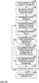
- a video coder may partition a current PU into a plurality of sub-PUs. Furthermore, the video coder may determine default motion parameters. In addition, the video coder may process sub-PUs from the plurality of sub-PUs in a particular order. In some instances, the video coder may determine the default motion parameters prior to processing any of the sub-PUs. For each respective PU of the current PU, the video coder may determine a reference block for the respective sub-PU. If the reference block for the respective sub-PU is coded using motion compensated prediction, the video coder may set motion parameters of the respective sub-PU based on motion parameters of the reference block for the respective sub-PU. However, if the reference block for the respective sub-PU is not coded using motion compensated prediction, the video coder may set the motion parameters of the respective sub-PU to the default motion parameters.
- the motion parameters of the respective sub-PU are not set in response to a subsequent determination that a reference block for any later sub-PU in the particular order is coded using motion compensated prediction.
- the video coder may not need to scan forward to find a sub-PU whose corresponding reference block is coded using motion compensated prediction or delay determining the motion parameters of the respective sub-PU until the video coder encounters, during the processing of the sub-PUs, a PU whose corresponding reference block is coded using motion compensated prediction.
- this may decrease complexity and coding delay.
- FIG. 1 is a block diagram illustrating an example video coding system 10 that may utilize the techniques of this disclosure.
- video coder refers generically to both video encoders and video decoders.
- video coding or “coding” may refer generically to video encoding or video decoding.
- video coding system 10 includes a source device 12 and a destination device 14.
- Source device 12 generates encoded video data. Accordingly, source device 12 may be referred to as a video encoding device or a video encoding apparatus.
- Destination device 14 may decode the encoded video data generated by source device 12. Accordingly, destination device 14 may be referred to as a video decoding device or a video decoding apparatus.
- Source device 12 and destination device 14 may be examples of video coding devices or video coding apparatuses.
- Source device 12 and destination device 14 may comprise a wide range of devices, including desktop computers, mobile computing devices, notebook (e.g., laptop) computers, tablet computers, set-top boxes, telephone handsets such as so-called “smart" phones, televisions, cameras, display devices, digital media players, video gaming consoles, in-car computers, or the like.
- desktop computers mobile computing devices
- notebook (e.g., laptop) computers tablet computers
- set-top boxes telephone handsets such as so-called “smart" phones
- televisions cameras
- display devices digital media players
- video gaming consoles in-car computers, or the like.
- Destination device 14 may receive encoded video data from source device 12 via a channel 16.
- Channel 16 may comprise one or more media or devices capable of moving the encoded video data from source device 12 to destination device 14.
- channel 16 may comprise one or more communication media that enable source device 12 to transmit encoded video data directly to destination device 14 in real-time.
- source device 12 may modulate the encoded video data according to a communication standard, such as a wireless communication protocol, and may transmit the modulated video data to destination device 14.
- the one or more communication media may include wireless and/or wired communication media, such as a radio frequency (RF) spectrum or one or more physical transmission lines.
- RF radio frequency
- the one or more communication media may form part of a packet-based network, such as a local area network, a wide-area network, or a global network (e.g., the Internet).
- the one or more communication media may include routers, switches, base stations, or other equipment that facilitate communication from source device 12 to destination device 14.
- channel 16 may include a storage medium that stores encoded video data generated by source device 12.
- destination device 14 may access the storage medium, e.g., via disk access or card access.
- the storage medium may include a variety of locally-accessed data storage media such as Blu-ray discs, DVDs, CD-ROMs, flash memory, or other suitable digital storage media for storing encoded video data.
- channel 16 may include a file server or another intermediate storage device that stores encoded video data generated by source device 12.
- destination device 14 may access encoded video data stored at the file server or other intermediate storage device via streaming or download.
- the file server may be a type of server capable of storing encoded video data and transmitting the encoded video data to destination device 14.
- Example file servers include web servers (e.g., for a website), file transfer protocol (FTP) servers, network attached storage (NAS) devices, and local disk drives.
- Destination device 14 may access the encoded video data through a standard data connection, such as an Internet connection.
- Example types of data connections may include wireless channels (e.g., Wi-Fi connections), wired connections (e.g., digital subscriber line (DSL), cable modem, etc.), or combinations of both that are suitable for accessing encoded video data stored on a file server.
- the transmission of encoded video data from the file server may be a streaming transmission, a download transmission, or a combination of both.
- video coding system 10 may be configured to support one-way or two-way video transmission to support applications such as video streaming, video playback, video broadcasting, and/or video telephony.
- FIG. 1 is merely an example and the techniques of this disclosure may apply to video coding settings (e.g., video encoding or video decoding) that do not necessarily include any data communication between the encoding and decoding devices.
- data is retrieved from a local memory, streamed over a network, or the like.
- a video encoding device may encode and store data to memory, and/or a video decoding device may retrieve and decode data from memory.
- the encoding and decoding is performed by devices that do not communicate with one another, but simply encode data to memory and/or retrieve and decode data from memory.
- source device 12 includes a video source 18, a video encoder 20, and an output interface 22.
- output interface 22 may include a modulator/demodulator (modem) and/or a transmitter.
- Video source 18 may include a video capture device, e.g., a video camera, a video archive containing previously-captured video data, a video feed interface to receive video data from a video content provider, and/or a computer graphics system for generating video data, or a combination of such sources of video data.
- Video encoder 20 may encode video data from video source 18.
- source device 12 directly transmits the encoded video data to destination device 14 via output interface 22.
- the encoded video data may also be stored onto a storage medium or a file server for later access by destination device 14 for decoding and/or playback.
- destination device 14 includes an input interface 28, a video decoder 30, and a display device 32.
- input interface 28 includes a receiver and/or a modem.
- Input interface 28 may receive encoded video data over channel 16.
- Video decoder 30 may decode encoded video data.
- Display device 32 may display the decoded video data. Display device 32 may be integrated with or may be external to destination device 14.
- Display device 32 may comprise a variety of display devices, such as a liquid crystal display (LCD), a plasma display, an organic light emitting diode (OLED) display, or another type of display device.
- LCD liquid crystal display
- OLED organic light emitting diode
- Video encoder 20 and video decoder 30 each may be implemented as any of a variety of suitable circuitry, such as one or more microprocessors, digital signal processors (DSPs), application-specific integrated circuits (ASICs), field-programmable gate arrays (FPGAs), discrete logic, hardware, or any combinations thereof. If the techniques are implemented partially in software, a device may store instructions for the software in a suitable, non-transitory computer-readable storage medium and may execute the instructions in hardware using one or more processors to perform the techniques of this disclosure. Any of the foregoing (including hardware, software, a combination of hardware and software, etc.) may be considered to be one or more processors. Each of video encoder 20 and video decoder 30 may be included in one or more encoders or decoders, either of which may be integrated as part of a combined encoder/decoder (CODEC) in a respective device.
- CODEC combined encoder/decoder
- This disclosure may generally refer to video encoder 20 "signaling" certain information to another device, such as video decoder 30.
- the term “signaling” may generally refer to the communication of syntax elements and/or other data used to decode the compressed video data. Such communication may occur in real- or near-real-time. Alternately, such communication may occur over a span of time, such as might occur when storing syntax elements to a computer-readable storage medium in an encoded bitstream at the time of encoding, which then may be retrieved by a decoding device at any time after being stored to this medium.
- video encoder 20 and video decoder 30 operate according to a video compression standard, such as ISO/IEC MPEG-4 Visual and ITU-T H.264 (also known as ISO/IEC MPEG-4 AVC), including its Scalable Video Coding (SVC) extension, Multiview Video Coding (MVC) extension, and MVC-based 3DV extension.
- SVC Scalable Video Coding
- MVC Multiview Video Coding
- MVC-based 3DV extension any bitstream conforming to the MVC-based 3DV extension of H.264/AVC always contains a sub-bitstream that is compliant to the MVC extension of H.264/AVC.
- 3DV three-dimensional video
- video encoder 20 and video decoder 30 may operate according to ITU-T H.261, ISO/IEC MPEG-1 Visual, ITU-T H.262 or ISO/IEC MPEG-2 Visual, and ITU-T H.264, ISO/IEC Visual.
- video encoder 20 and video decoder 30 may operate according to the High Efficiency Video Coding (HEVC) standard developed by the Joint Collaboration Team on Video Coding (JCT-VC) of ITU-T Video Coding Experts Group (VCEG) and ISO/IEC Motion Picture Experts Group (MPEG).
- HEVC Working Draft 10 A draft of the HEVC standard, referred to as "HEVC Working Draft 10" is described in Bross et al., "High Efficiency Video Coding (HEVC) text specification draft 10 (for FDIS & Consent),” Joint Collaborative Team on Video Coding (JCT-VC) of ITU-T SG16 WP3 and ISO/IEC JTC1/SC29/WG11, 12th Meeting, Geneva, CH, Jan.
- HEVC Working Draft 10 or the “HEVC base specification”
- SHEVC High Efficiency Video Coding Extension
- MV-HEVC Test Model 4 Joint Collaboration Team on 3D Video Coding (JCT-3V) of VCEG and MPEG is currently developing a multi-view coding extension of HEVC (i.e., MV-HEVC).
- MV-HEVC Draft Text 4 Joint Collaborative Team on 3D Video Coding Extension Development of ITU-T SG 16 WP 3 and ISO/IEC JTC 1/SC 29/WG 11, 4nd Meeting: Incheon, KR, Apr. 2013
- HLS high-level syntax
- MV-HEVC only provides for high-level syntax changes and not for low-level syntax changes, such as those at the CU/PU level.
- the JCT-3V of VCEG and MPEG is developing a 3DV standard based on HEVC, for which part of the standardization efforts includes the standardization of the multi-view video codec based on HEVC (MV-HEVC) and another part for 3D video coding based on HEVC (3D-HEVC).
- MV-HEVC multi-view video codec based on HEVC
- 3D-HEVC 3D-HEVC
- new coding tools including those in at the CU and/or PU level, for both texture and depth views may be included and supported.
- 3D-HEVC software for 3D-HEVC
- 3D-HTM software for 3D-HEVC
- 3D-HTM version 7.0 https://hevc.hhi.fraunhofer.de/svn/svn_3DVCSoftware/tags/HTM-7.0/
- 3D-HEVC Test Model 4 JCT3V-D1005_spec_v1 Joint Collaborative Team on 3D Video Coding Extension Development of ITU-T SG 16 WP 3 and ISO/IEC JTC 1/SC 29/WG 11, 4nd Meeting: Incheon, KR, Apr. 2013 (hereinafter, "3D-HEVC Test Model 4"), which as of December 17, 2013, is downloadable from the following link: http://phenix.it-sudparis.eu/jct2/doc_end_user/documents/2_Shanghai/wg11/JCT3V-B1005-v1.zip.
- 3D-HEVC Test Model 3 is another version of the reference software description of 3D-HEVC.
- 3D-HEVC is also described in Tech et al., "3D-HEVC Draft Text 2," Joint Collaborative Team on 3D Video Coding Extension Development of ITU-T SG 16 WP 3 and ISO/IEC JTC 1/SC 29/WG 11, 6th Meeting: Geneva, CH, 25 Oct. - 1 Nov. 2013 , document no. JCT3V-F1001-v2 (hereinafter, "3D-HEVC Draft Text 2").
- Video encoder 20 and video decoder 30 may operate according to SHEVC, MV-HEVC, and/or 3D-HEVC.
- a video sequence typically includes a series of pictures. Pictures may also be referred to as "frames.”
- a picture may include three sample arrays, denoted S L , S Cb , and S Cr .
- S L is a two-dimensional array (i.e., a block) of luma samples.
- S Cb is a two-dimensional array of Cb chrominance samples.
- S Cr is a two-dimensional array of Cr chrominance samples.
- Chrominance samples may also be referred to herein as "chroma" samples.
- a picture may be monochrome and may only include an array of luma samples.
- video encoder 20 may generate a set of coding tree units (CTUs).
- Each of the CTUs may comprise a coding tree block of luma samples, two corresponding coding tree blocks of chroma samples, and syntax structures used to code the samples of the coding tree blocks.
- a CTU may comprise a single coding tree block and syntax structures used to code the samples of the coding tree block.
- a coding tree block may be an NxN block of samples.
- a CTU may also be referred to as a "tree block” or a "largest coding unit” (LCU).
- the CTUs of HEVC may be broadly analogous to the macroblocks of other standards, such as H.264/AVC.
- a CTU is not necessarily limited to a particular size and may include one or more coding units (CUs).
- a slice may include an integer number of CTUs ordered consecutively in a raster scan order.
- video unit or “video block” or “block” to refer to one or more sample blocks and syntax structures used to code samples of the one or more blocks of samples.
- Example types of video units may include CTUs, CUs, PUs, transform units (TUs), macroblocks, macroblock partitions, and so on.
- discussion of PUs may be interchanged with discussion of macroblocks or macroblock partitions.
- video encoder 20 may recursively perform quad-tree partitioning on the coding tree blocks of a CTU to divide the coding tree blocks into coding blocks, hence the name "coding tree units."
- a coding block is an NxN block of samples.
- a CU may comprise a coding block of luma samples and two corresponding coding blocks of chroma samples of a picture that has a luma sample array, a Cb sample array, and a Cr sample array, and syntax structures used to code the samples of the coding blocks.
- a CU may comprise a single coding block and syntax structures used to code the samples of the coding block.
- Video encoder 20 may partition a coding block of a CU into one or more prediction blocks.
- a prediction block is a rectangular (i.e., square or non-square) block of samples on which the same prediction is applied.
- a prediction unit (PU) of a CU may comprise a prediction block of luma samples, two corresponding prediction blocks of chroma samples, and syntax structures used to predict the prediction blocks. In monochrome pictures or pictures having three separate color planes, a PU may comprise a single prediction block and syntax structures used to predict the prediction block.
- Video encoder 20 may generate predictive luma, Cb, and Cr blocks for luma, Cb, and Cr prediction blocks of each PU of the CU.
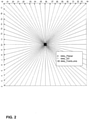
- Video encoder 20 may use intra prediction or inter prediction to generate the predictive blocks for a PU. If video encoder 20 uses intra prediction to generate the predictive blocks of a PU, video encoder 20 may generate the predictive blocks of the PU based on decoded samples of the picture associated with the PU. In some versions of HEVC, for the luma component of each PU, an intra prediction method is utilized with 33 angular prediction modes (indexed from 2 to 34), DC mode (indexed with 1) and Planar mode (indexed with 0), as shown in FIG. 2.
- FIG. 2 is a conceptual diagram illustrating example intra prediction modes in HEVC.
- video encoder 20 may generate the predictive blocks of the PU based on decoded samples of one or more pictures other than the picture associated with the PU.
- Inter prediction may be uni-directional inter prediction (i.e., uni-prediction) or bi-directional inter prediction (i.e., bi-prediction).
- video encoder 20 may generate a first reference picture list (RefPicList0) for a current slice and may, in some instances, also generate a second reference picture list (RefPicList1) for the current slice.
- Each of the reference picture lists may include one or more reference pictures.
- video encoder 20 may search the reference pictures in either or both RefPicList0 and RefPicList1 to determine a reference location within a reference picture. Furthermore, when using uni-prediction, video encoder 20 may generate, based at least in part on samples corresponding to the reference location, the predictive sample blocks for the PU. Moreover, when using uni-prediction, video encoder 20 may generate a single motion vector that indicates a spatial displacement between a prediction block of the PU and the reference location.
- a motion vector may include a horizontal component specifying a horizontal displacement between the prediction block of the PU and the reference location and may include a vertical component specifying a vertical displacement between the prediction block of the PU and the reference location.
- video encoder 20 may determine a first reference location in a reference picture in RefPicList0 and a second reference location in a reference picture in RefPicList1. Video encoder 20 may then generate, based at least in part on samples corresponding to the first and second reference locations, the predictive blocks for the PU. Moreover, when using bi-prediction to encode the PU, video encoder 20 may generate a first motion vector indicating a spatial displacement between a sample block of the PU and the first reference location and a second motion vector indicating a spatial displacement between the prediction block of the PU and the second reference location.
- a reference picture list construction for the first or the second reference picture list (e.g., RefPicList0 or RefPicList1) of a B picture includes two steps: reference picture list initialization and reference picture list reordering (modification).
- the reference picture list initialization is an explicit mechanism that puts the reference pictures in the reference picture memory (also known as decoded picture buffer (DPB)) into a list based on the order of POC (Picture Order Count, aligned with display order of a picture) values.
- POC Picture Order Count, aligned with display order of a picture
- the reference picture list reordering mechanism can modify the position of a picture that was put in the list during the reference picture list initialization to any new position, or put any reference picture in the reference picture memory in any position even the picture does not belong to the initialized list.
- Some pictures after the reference picture list reordering (modification), may be put in a very further position in the list. However, if a position of a picture exceeds the number of active reference pictures of the list, the picture is not considered as an entry of the final reference picture list.
- the number of active reference pictures for each list may be signaled in a slice header.
- reference picture lists are constructed (namely RefPicList0 and RefPicList1, if available)
- a reference index to a reference picture list can be used to identify any reference picture included in the reference picture list.
- video encoder 20 may generate one or more residual blocks for the CU. For instance, video encoder 20 may generate a luma residual block for the CU. Each sample in the CU's luma residual block indicates a difference between a luma sample in one of the CU's predictive luma blocks and a corresponding sample in the CU's original luma coding block. In addition, video encoder 20 may generate a Cb residual block for the CU.
- predictive blocks e.g., luma, Cb, and Cr blocks
- Each sample in the CU's Cb residual block may indicate a difference between a Cb sample in one of the CU's predictive Cb blocks and a corresponding sample in the CU's original Cb coding block.
- Video encoder 20 may also generate a Cr residual block for the CU.
- Each sample in the CU's Cr residual block may indicate a difference between a Cr sample in one of the CU's predictive Cr blocks and a corresponding sample in the CU's original Cr coding block.
- video encoder 20 may use quad-tree partitioning to decompose the residual blocks (e.g., the luma, Cb, and Cr residual blocks) of a CU into one or more transform blocks (e.g., luma, Cb, and Cr transform blocks).
- a transform block is a rectangular (e.g., square or non-square) block of samples on which the same transform is applied.
- a transform unit (TU) of a CU may comprise a transform block of luma samples, two corresponding transform blocks of chroma samples, and syntax structures used to transform the transform block samples.
- each TU of a CU may be associated with a luma transform block, a Cb transform block, and a Cr transform block.
- the luma transform block associated with the TU may be a sub-block of the CU's luma residual block.
- the Cb transform block may be a sub-block of the CU's Cb residual block.
- the Cr transform block may be a sub-block of the CU's Cr residual block.
- a TU may comprise a single transform block and syntax structures used to transform the samples of the transform block.
- Video encoder 20 may apply one or more transforms a transform block of a TU to generate a coefficient block for the TU. For instance, video encoder 20 may apply one or more transforms to a luma transform block of a TU to generate a luma coefficient block for the TU. A coefficient block may be a two-dimensional array of transform coefficients. A transform coefficient may be a scalar quantity. Video encoder 20 may apply one or more transforms to a Cb transform block of a TU to generate a Cb coefficient block for the TU. Video encoder 20 may apply one or more transforms to a Cr transform block of a TU to generate a Cr coefficient block for the TU.
- video encoder 20 may quantize the coefficient block. Quantization generally refers to a process in which transform coefficients are quantized to possibly reduce the amount of data used to represent the transform coefficients, providing further compression.
- video encoder 20 may entropy encode syntax elements indicating the quantized transform coefficients. For example, video encoder 20 may perform Context-Adaptive Binary Arithmetic Coding (CABAC) on the syntax elements indicating the quantized transform coefficients.
- CABAC Context-Adaptive Binary Arithmetic Coding
- Video encoder 20 may output a bitstream that includes a sequence of bits that forms a representation of coded pictures and associated data.
- the bitstream may comprise a sequence of network abstraction layer (NAL) units.
- NAL unit is a syntax structure containing an indication of the type of data in the NAL unit and bytes containing that data in the form of a raw byte sequence payload (RBSP) interspersed as necessary with emulation prevention bits.
- Each of the NAL units includes a NAL unit header and encapsulates a RBSP.
- the NAL unit header may include a syntax element that indicates a NAL unit type code.
- the NAL unit type code specified by the NAL unit header of a NAL unit indicates the type of the NAL unit.
- a RBSP may be a syntax structure containing an integer number of bytes that is encapsulated within a NAL unit. In some instances, an RBSP includes zero bits.
- NAL units may encapsulate different types of RBSPs.
- different types of NAL unit may encapsulate different RBSPs for video parameter sets (VPSs), sequence parameter sets (SPSs), picture parameter sets (PPSs), coded slices, supplemental enhancement information (SEI), and so on.
- NAL units that encapsulate RBSPs for video coding data may be referred to as video coding layer (VCL) NAL units.
- SPSs may contain information that applies to all slices of a coded video sequence (CVS).
- a CVS may comprise a sequence of pictures.
- a CVS may start from an instantaneous decoding refresh (IDR) picture, or a broken link access (BLA) picture, or a clean random access (CRA) picture that is the first picture in the bitstream, including all subsequent pictures that are not an IDR or BLA picture.
- IDR instantaneous decoding refresh
- BLA broken link access
- CRA clean random access
- a CVS may comprise a sequence of access units that may consist, in decoding order, of a CRA access unit that is the first access unit in the bitstream, an IDR access unit or a BLA access unit, followed by zero or more non-IDR and non-BLA access units including all subsequent access units up to but not including any subsequent IDR or BLA access unit.
- an access unit may be a set of NAL units that are consecutive in decoding order and contain exactly one coded picture.
- the access unit may also contain other NAL units not containing slices of the coded picture.
- the decoding of an access unit always results in a decoded picture.
- a VPS is a syntax structure comprising syntax elements that apply to zero or more entire CVSs.
- An SPS is also a syntax structure comprising syntax elements that apply to zero or more entire CVSs.
- An SPS may include a syntax element that identifies a VPS that is active when the SPS is active. Thus, the syntax elements of a VPS may be more generally applicable than the syntax elements of an SPS.
- a PPS is a syntax structure comprising syntax elements that apply to zero or more coded pictures.
- a PPS may include a syntax element that identifies an SPS that is active when the PPS is active.
- a slice header of a slice may include a syntax element that indicates a PPS that is active when the slice is being coded.
- Video decoder 30 may receive a bitstream generated by video encoder 20.
- video decoder 30 may parse the bitstream to obtain syntax elements from the bitstream.
- Video decoder 30 may reconstruct the pictures of the video data based at least in part on the syntax elements obtained from the bitstream.
- the process to reconstruct the video data may be generally reciprocal to the process performed by video encoder 20. For instance, video decoder 30 may use motion vectors of PUs to determine predictive blocks for the PUs of a current CU.
- video decoder 30 may inverse quantize coefficient blocks associated with TUs of the current CU. Video decoder 30 may perform inverse transforms on the coefficient blocks to reconstruct transform blocks associated with the TUs of the current CU.
- Video decoder 30 may reconstruct the coding blocks of the current CU by adding the samples of the predictive blocks for PUs of the current CU to corresponding samples of the transform blocks of the TUs of the current CU. By reconstructing the coding blocks for each CU of a picture, video decoder 30 may reconstruct the picture.
- video encoder 20 may signal the motion information of a PU using merge mode or advanced motion vector prediction (AMVP) mode.
- AMVP advanced motion vector prediction
- Motion prediction may comprise the determination of motion information of a block (e.g., a PU) based on motion information of one or more other blocks.
- the motion information (also referred to herein as motion parameters) of a PU may include motion vector(s) of the PU and reference index(s) of the PU.
- video encoder 20 When video encoder 20 signals the motion information of a current PU using merge mode, video encoder 20 generates a merge candidate list. In other words, video encoder 20 may perform a motion vector predictor list construction process.
- the merge candidate list includes a set of merge candidates that indicate the motion information of PUs that spatially or temporally neighbor the current PU. That is, in the merge mode, a candidate list of motion parameters (e.g., reference indexes, motion vectors, etc.) is constructed where a candidate can be from spatial and temporal neighboring blocks.
- motion parameters e.g., reference indexes, motion vectors, etc.
- video encoder 20 may select a merge candidate from the merge candidate list and may use the motion information indicated by the selected merge candidate as the motion information of the current PU.
- Video encoder 20 may signal the position in the merge candidate list of the selected merge candidate. For instance, video encoder 20 may signal the selected motion vector parameters by transmitting an index into the candidate list.
- Video decoder 30 may obtain, from the bitstream, the index into the candidate list (i.e., a candidate list index).
- video decoder 30 may generate the same merge candidate list and may determine, based on the indication of the position of the selected merge candidate, the selected merge candidate. Video decoder 30 may then use the motion information of the selected merge candidate to generate predictive blocks for the current PU.
- video decoder 30 may determine, based at least in part on the candidate list index, a selected candidate in the candidate list, wherein the selected candidate specifies the motion vector for the current PU. In this way, at the decoder side, once the index is decoded, all motion parameters of the corresponding block where the index points may be inherited by the current PU.
- Skip mode is similar to merge mode.
- video encoder 20 and video decoder 30 generate and use a merge candidate list in the same way that video encoder 20 and video decoder 30 use the merge candidate list in merge mode.
- video encoder 20 signals the motion information of a current PU using skip mode
- video encoder 20 does not signal any residual data for the current PU.
- video decoder 30 may determine, without use of residual data, a predictive block for the PU based on a reference block indicated by the motion information of a selected candidate in the merge candidate list.
- AMVP mode is similar to merge mode in that video encoder 20 may generate a candidate list and may select a candidate from the candidate list.
- video encoder 20 may signal a RefPicListX motion vector difference (MVD) for the current PU and a RefPicListX reference index for the current PU in addition to signaling a RefPicListX MVP flag for the current PU.
- the RefPicListX MVP flag for the current PU may indicate the position of a selected AMVP candidate in the AMVP candidate list.
- the RefPicListX MVD for the current PU may indicate a difference between a RefPicListX motion vector of the current PU and a motion vector of the selected AMVP candidate.
- video encoder 20 may signal the RefPicListX motion information of the current PU by signaling a RefPicListX motion vector predictor (MVP) flag, a RefPicListX reference index value, and a RefPicListX MVD.
- MVP RefPicListX motion vector predictor
- the data in the bitstream representing the motion vector for the current PU may include data representing a reference index, an index to a candidate list, and an MVD.
- video decoder 30 may obtain, from the bitstream, a MVD for a current PU and a MVP flag. Video decoder 30 may generate the same AMVP candidate list and may determine, based on the MVP flag, the selected AMVP candidate. Video decoder 30 may recover a motion vector of the current PU by adding the MVD to the motion vector indicated by the selected AMVP candidate. That is, video decoder 30 may determine, based on a motion vector indicated by the selected AMVP candidate and the MVD, the motion vector of the current PU. Video decoder 30 may then use the recovered motion vector or motion vectors of the current PU to generate predictive blocks for the current PU.
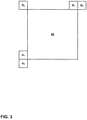
- FIG. 3 is a conceptual diagram illustrating example spatially-neighboring PUs relative to a current block 40.
- the spatially-neighboring PUs may be PUs that cover the locations indicated as A 0 , A 1 , B 0 , B 1 , and B 2 .
- a PU may cover a location when a prediction block of the PU includes the location.
- a candidate in a merge candidate list or an AMVP candidate list that is based on the motion information of a PU that temporally neighbors a current PU may be referred to as a temporal motion vector predictor.
- the use of a temporal motion vector prediction may be referred to as a temporal motion vector prediction (TMVP).
- TMVP may be used to improve the coding efficiency of HEVC and, different from other coding tools, TMVP may need to access the motion vector of a frame in a decoded picture buffer, more specifically in a reference picture list.
- TMVP may be enabled or disabled on a CVS-by-CVS basis, a slice-by-slice basis, or on another basis.
- a syntax element e.g., sps_temporal_mvp_enable_flag
- TMVP may be enabled or disabled for particular slices within the CVS.
- a syntax element e.g., slice_temporal_mvp_enable_flag
- slice_temporal_mvp_enable_flag in a slice header may indicate whether TMVP is enabled for a slice.
- TMVP when TMVP is enabled for a whole CVS (e.g., sps_temporal_mvp_enable_flag in a SPS is set to 1), a slice_temporal_mvp_enable_flag is signaled in the slice header to indicate whether TMVP is enabled for the current slice.
- a video coder may firstly identify a reference picture that includes a PU that is co-located with the current PU. In other words, the video coder may identify a so-called "co-located picture.” If the current slice of the current picture is a B slice (i.e., a slice that is allowed to include bi-directionally inter predicted PUs), video encoder 20 may signal, in a slice header, a syntax element (e.g., collocated_from_10_flag) that indicates whether the co-located picture is from RefPicListO or RefPicList1.
- a syntax element e.g., collocated_from_10_flag
- video encoder 20 may signal a syntax element (e.g., collocated_from_10_flag) in a slice header to indicate whether the co-located picture is in RefPicList0 or RefPicList1.
- a syntax element e.g., collocated_from_10_flag
- a syntax element (e.g., collocated_ref_idx) in a slice header may indicate a co-located picture in the identified reference picture list.
- video decoder 30 may use collocated_ref_idx, which may be signaled in a slice header, to identify the co-located picture in the identified reference picture list.
- the video coder may identify a co-located PU by checking the co-located picture.
- the temporal motion vector predictor may indicate either the motion information of a right-bottom PU a co-located PU, or the motion information of a center PU of the co-located PU.
- the video coder may scale the motion vectors based on the temporal location (reflected by POC value). For instance, a video coder may increase the magnitude of a motion vector by greater amounts when a difference between the POC values of a current picture and a reference picture is greater than when a difference between the POC values of the current picture and the reference picture is less.
- the target reference index of all possible reference picture lists for the temporal merging candidate derived from a temporal motion vector predictor may be always set to 0.
- the target reference index of all possible reference pictures may be set equal to a decoded reference index.
- the target reference index of all possible reference picture lists for the temporal merging candidate derived from TMVP is always set to 0 while for AMVP, the temporal merging candidate may be set equal to the decoded reference index.
- a SPS may include a flag (e.g., sps_temporal_mvp_enable_flag) and the slice header may include a flag (e.g., pic_temporal_mvp_enable_flag) when sps_temporal_mvp_enable_flag is equal to 1.
- pic_temporal_mvp_enable_flag e.g., pic_temporal_mvp_enable_flag
- the techniques of this disclosure are potentially applicable to multi-view coding and/or 3DV standards and specifications, including MV-HEVC and 3D-HEVC.
- multi-view coding such as that defined in MV-HEVC and 3D-HEVC
- the term "access unit" may be used to refer to the set of pictures that correspond to the same time instance.
- an access unit may be a set of NAL units that are associated with each other according to a specified classification rule, are consecutive in decoding order, and contain the VCL NAL units of all coded pictures associated with the same output time and their associated non-VCL NAL units.
- video data may be conceptualized as a series of access units occurring over time.
- a "view component” may be a coded representation of a view in a single access unit.
- a view component may contain a depth view component and a texture view component.
- a depth view component may be a coded representation of the depth of a view in a single access unit.
- a texture view component may be a coded representation of the texture of a view in a single access unit.
- a "view” may refer to a sequence of view components associated with the same view identifier.
- the texture view component and the depth view component within a set of pictures of a view may be considered as corresponding to one another.
- the texture view component within a set of pictures of a view is considered as corresponding to the depth view component within the set of the pictures of the view, and vice-versa (i.e., the depth view component corresponds to its texture view component in the set, and vice-versa).
- a texture view component that corresponds to a depth view component may be considered as the texture view component and the depth view component being part of a same view of a single access unit.
- the texture view component includes the actual image content that is displayed.
- the texture view component may include luma (Y) and chroma (Cb and Cr) components.
- the depth view component may indicate relative depths of the pixels in its corresponding texture view component.
- the depth view component is a gray scale image that includes only luma values. In other words, the depth view component may not convey any image content, but rather provide a measure of the relative depths of the pixels in the texture view component.
- a purely white pixel in the depth view component indicates that its corresponding pixel or pixels in the corresponding texture view component is closer from the perspective of the viewer, and a purely black pixel in the depth view component indicates that its corresponding pixel or pixels in the corresponding texture view component is further away from the perspective of the viewer.
- the various shades of gray in between black and white indicate different depth levels. For instance, a very gray pixel in the depth view component indicates that its corresponding pixel in the texture view component is further away than a slightly gray pixel in the depth view component. Because only gray scale is needed to identify the depth of pixels, the depth view component need not include chroma components, as color values for the depth view component may not serve any purpose.
- the depth view component using only luma values (e.g., intensity values) to identify depth is provided for illustration purposes and should not be considered limiting. In other examples, any technique may be utilized to indicate relative depths of the pixels in the texture view component.
- a view may be referred to as a "base view” if a video decoder (e.g., video decoder 30) can decode pictures in the view without reference to pictures in any other view.
- a video coder such as video encoder 20 or video decoder 30
- may add a picture into a reference picture list e.g., RefPicList0 or RefPicList1 if the picture is in a different view but within a same time instance (i.e., access unit) as the picture that the video coder is currently coding.
- the video coder may insert an inter-view prediction reference picture at any position of a reference picture list.
- Multi-view coding supports inter-view prediction.
- Inter-view prediction is similar to the inter prediction used in H.264/AVC, HEVC, or other video coding specifications and may use the same syntax elements.
- a video coder performs inter-view prediction on a current block (such as a macroblock, CU, or PU)
- video encoder 20 may use, as a reference picture, a picture that is in the same access unit as the current block, but in a different view.
- inter-view prediction is performed among pictures captured in the different views of the same access unit (i.e., within the same time instance) to remove correlation between views.
- conventional inter prediction only uses pictures in different access units as reference pictures.
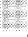
- FIG. 4 is a conceptual diagram illustrating an example multi-view decoding order.
- the multi-view decoding order may be a bitstream order.
- each square corresponds to a view component.
- Columns of squares correspond to access units.
- Each access unit may be defined to contain the coded pictures of all the views of a time instance. Rows of squares correspond to views.
- the access units are labeled T0...T8 and the views are labeled S0...S7. Because each view component of an access unit is decoded before any view component of the next access unit, the decoding order of FIG. 4 may be referred to as time-first coding.
- the decoding order of access units may not be identical to the output or display order of the views.
- FIG. 5 is a conceptual diagram illustrating an example prediction structure for multi-view coding.
- the multi-view prediction structure of FIG. 5 includes temporal and inter-view prediction.
- each square corresponds to a view component.
- the access units are labeled T0...T11 and the views are labeled S0...S7.
- Squares labeled "I” are intra predicted view components.
- Squares labeled "P” are uni-directionally inter predicted view components.
- Squares labeled "B” and “b” are bi-directionally inter predicted view components. Squares labeled "b” may use squares labeled "B" as reference pictures.
- An arrow that points from a first square to a second square indicates that the first square is available in inter prediction as a reference picture for the second square.
- view components in different views of the same access unit may be available as reference pictures.
- the use of one view component of an access unit as a reference picture for another view component of the same access unit may be referred to as inter-view prediction.
- inter-view prediction is supported by disparity motion compensation, which uses the syntax of the H.264/AVC motion compensation, but allows a picture in a different view to be used as a reference picture. Coding of two views may also be supported by the MVC extension of H.264/AVC.
- disparity motion compensation uses the syntax of the H.264/AVC motion compensation, but allows a picture in a different view to be used as a reference picture. Coding of two views may also be supported by the MVC extension of H.264/AVC.
- One of the advantages of the MVC extension of H.264/AVC is that an MVC encoder may take more than two views as a 3D video input and an MVC decoder may decode such a multi-view representation. Consequently, any renderer with a MVC decoder may expect 3D video contents with more than two views.
- motion vectors there are two kinds of motion vectors.
- One kind of motion vector is a normal motion vector that points to a temporal reference picture.
- the type of inter prediction corresponding to a normal, temporal motion vector may be referred to as "motion-compensated prediction" or "MCP.”
- MCP motion-compensated prediction
- the corresponding motion vector is referred to as a "disparity motion vector.”
- a disparity motion vector points to a picture in a different view (i.e., an inter-view reference picture).
- the type of inter prediction corresponding to a disparity motion vector may be referred to as "disparity-compensated prediction" or "DCP.”
- 3D-HEVC may improve coding efficiency using inter-view motion prediction and inter-view residual prediction.
- two new technologies namely "inter-view motion prediction” and "inter-view residual prediction” have been adopted in reference software.
- inter-view motion prediction a video coder may determine (i.e., predict) the motion information of a current PU based on the motion information of a PU in a different view than the current PU.
- inter-view residual prediction a video coder may determine residual blocks of a current CU based on residual data in a different view than the current CU.
- a video coder may determine disparity vectors for blocks (e.g., PUs, CUs, etc.).
- the first step is to derive a disparity vector.
- a disparity vector is used as an estimator of the displacement between two views.
- a video coder may use a disparity vector for a block either to locate a reference block in another view for inter-view motion or residual prediction, or the video coder may convert the disparity vector to a disparity motion vector for inter-view motion prediction. That is, the disparity vector may be used to either locate the corresponding block in the other view for inter-view motion/residual prediction or may be converted to a disparity motion vector for inter-view motion prediction.
- the video coder may use the method of Neighboring Blocks Based Disparity Vector (NBDV) derivation to derive the disparity vector for a PU (i.e., the current PU).
- NBDV Neighboring Blocks Based Disparity Vector
- a process called NBDV derivation may be used in a test model for 3D-HEVC (i.e., 3D-HTM).
- the NBDV derivation process uses disparity motion vectors from spatial and temporal neighboring blocks to derive the disparity vector for the current block. Because neighboring blocks (e.g., blocks that spatially or temporally neighbor a current block) are likely to share almost the same motion and disparity information in video coding, the current block can use the motion vector information in the neighboring blocks as a predictor of the disparity vector of the current block. Thus, the NBDV derivation process uses the neighboring disparity information for estimating the disparity vector in different views.
- neighboring blocks e.g., blocks that spatially or temporally neighbor a current block
- the video coder may check, in a fixed checking order, motion vectors of spatially-neighboring and temporally-neighboring PUs.
- the video coder may determine whether the motion vector(s) are disparity motion vectors.
- a disparity motion vector of a PU of a picture is a motion vector pointing to a location within an inter-view reference picture of the picture.
- An inter-view reference picture of a picture may be a picture that is in the same access unit as the picture, but in a different view.
- An IDV may be a disparity vector of a spatially- or temporally-neighboring PU that is coded using inter-view prediction.
- An IDV may be generated when a PU employs inter-view motion vector prediction, i.e., the candidate for AMVP or merge modes is derived from a reference block in the other view with the help of a disparity vector.
- An IDV may be stored to the PU for the purpose of disparity vector derivation.
- the video coder may return the identified disparity motion vector or IDV.
- IDVs were included with a simplified version of the NBDV derivation process in Sung et al., "3D-CE5.h: Simplification of disparity vector derivation for HEVC-based 3D video coding, document JCTV3-A0126. " The use of IDVs in the NBDV derivation process was further simplified in Kang et al., “3D-CE5.h related: improvements for disparity vector derivation," document JCT3V-B0047 , by removing the IDVs stored in the decoded picture buffer and also providing improved coding gain with a random access point (RAP) picture selection.
- the video coder may convert the returned disparity motion vector or IDV to a disparity vector and may use the disparity vector for inter-view motion prediction and inter-view residual prediction.
- the video coder when the video coder performs the NBDV derivation process, the video coder checks disparity motion vectors in the temporal neighboring blocks, disparity motion vectors in the spatial neighboring blocks, and then the IDVs in order. Once the video coder finds a disparity motion vector for the current block, the video coder may terminate the NBDV derivation process. Thus, once a disparity motion vector or an IDV is identified, the checking process is terminated and the identified disparity motion vector is returned and converted to the disparity vector which will be used in inter-view motion prediction and inter-view residue prediction.
- the video coder When the video coder is unable to determine a disparity vector for the current block by performing the NBDV derivation process (i.e., when there is no disparity motion vector or IDV found during the NBDV derivation process), the video coder may mark the NBDV as unavailable.
- the video coder may use a zero disparity vector as the disparity vector for the current PU.
- the zero disparity vector is a disparity vector having both horizontal and vertical components equal to 0.
- the video coder may disable inter-view residual prediction for the current PU.
- the video coder may use inter-view motion prediction for the current PU. That is, if no disparity vector is found after checking all the pre-defined neighboring blocks, a zero disparity vector may be used for inter-view motion prediction while inter-view residual prediction may be disabled for the corresponding PU.
- the video coder may check spatially-neighboring PUs as part of the process of determining the disparity vector for the current PU.
- the video coder checks the following spatially-neighboring blocks: the below-left spatially-neighboring block, the left spatially-neighboring block, the above-right spatially-neighboring block, the above spatially-neighboring block, and the above-left spatially-neighboring block.
- the video coder checks the following spatially-neighboring blocks: the below-left spatially-neighboring block, the left spatially-neighboring block, the above-right spatially-neighboring block, the above spatially-neighboring block, and the above-left spatially-neighboring block.
- five spatial neighboring blocks are used for disparity vector derivation.
- the five spatially-neighboring blocks may cover the locations A 0 , A 1 , B 0 , B 1 , and B 2 , respectively, as indicated in FIG. 3 .
- the video coder may check the five spatially-neighboring blocks in the order of A 1 , B 1 , B 0 , A 0 , and B 2 .
- the same five spatially-neighboring blocks may be used in merge modes for HEVC. Therefore, in some examples, no additional memory access is required. If one of the spatially-neighboring blocks has a disparity motion vector, the video coder may terminate the checking process and the video coder may use the disparity motion vector as the final disparity vector for the current PU. In other words, if one of them uses a disparity motion vector, the checking process is terminated and the corresponding disparity motion vector will be used as the final disparity vector.
- the video coder may check temporally-neighboring PUs as part of the process to determine the disparity vector for the current PU.
- a construction process of a candidate picture list may be performed first.
- the video coder may check up to two reference pictures from the current view for disparity motion vectors.
- the first reference picture may be the co-located picture.
- the co-located picture i.e., the co-located reference picture
- the second reference picture may be a random access picture or a reference picture with a smallest POC value difference and a smallest temporal identifier.
- the co-located picture and the random-access picture or the reference picture with the smallest POC difference and smallest temporal ID are considered for temporal block checks.
- the video coder may check the random-access picture first, followed by the co-located picture.
- the video coder may check two blocks.
- the video coder may check a center block (CR) and a bottom-right block (BR).
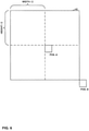
- FIG. 6 is a conceptual diagram illustrating example temporal neighboring blocks in the NBDV derivation process.
- the center block may be the center 4x4 block of a co-located region of the current PU.
- the bottom-right block may be the bottom-right 4x4 block of a co-located region of the current PU.
- the two blocks are checked in order, CR and BR for the first non-base view or BR, CR for the second non-base view.
- the video coder may terminate the checking process and may use the disparity motion vector as the final disparity vector for the current PU.
- decoding of pictures associated with the first non-base view may depend on decoding of pictures associated with a base view, but not pictures associated with other views.
- decoding of pictures associated with the second non-base view may depend on decoding of pictures associated with the base view and, in some instances, the first non-base view, but not pictures associated with other views, if present.
- a block 42 indicates a co-located region for a current PU. Furthermore, in the example of FIG. 6 , the block labeled "Pos. A" corresponds to the center block. The block labeled "Pos. B" corresponds to the bottom-right block. As indicated in the example of FIG. 6 , the center block may be located immediately below and to the right of the center of a center point of the co-located region.
- the video coder may check first whether the neighboring PU has a disparity motion vector. If the none of the neighboring PUs has a disparity motion vector, the video coder may determine whether any of the spatially-neighboring PUs have an IDV. In other words, whether disparity motion vectors are used is firstly checked for all the spatial/temporal neighboring blocks, followed by IDVs. Spatial neighboring blocks are firstly checked, followed by temporal neighboring blocks.
- the video coder may check the spatially-neighboring PUs in the order of A 0 , A 1 , B 0 , B 1 , and B 2 . If one of the spatially-neighboring PUs has an IDV and the IDV is coded as merge/skip mode, the video coder may terminate the checking process and may use the IDV as the final disparity vector for the current PU. In other words, five spatial neighboring blocks are checked in the order of A 0 , A 1 , B 0 , B 1 and B 2 . If one of them uses a IDV and it may be coded as skip/merge mode, the checking process is terminated and the corresponding IDV may be used as the final disparity vector.
- the disparity vector for a current block may indicate a location in a reference picture (i.e., a reference view component) in a reference view.
- the video coder is allowed to access depth information for the reference view.
- the video coder may apply a refinement process to refine the disparity vector for the current block further.
- the video coder may refine the disparity vector for the current block based on the reference picture's depth map. In other words, the disparity vector, generated from the NBDV scheme could be further refined using the information in the coded depth map.
- NBDV-R NBDV refinement
- Do-NBDV depth-oriented NBDV
- the video coder may further refine the disparity vector by retrieving depth data from the reference view's depth map.
- the refinement process includes the following steps:
- the video coder when the NBDV derivation process does not return an available disparity vector (e.g., when the NBDV derivation process returns a variable that indicates that the NBDV derivation process was unable to derive a disparity vector for the current block based on a disparity motion vector or an IDV of a neighboring block), the video coder does not perform the NBDV refinement process and the video coder may use, as the disparity vector for the current block, the zero disparity vector. In other words, when NBDV derivation process does not provide an available disparity vector, and thus the result of NBDV derivation process is unavailable, the above NBDV-R process is skipped and a zero disparity vector is directly returned.
- an available disparity vector e.g., when the NBDV derivation process returns a variable that indicates that the NBDV derivation process was unable to derive a disparity vector for the current block based on a disparity motion vector or an IDV of a neighboring block
- the video coder uses a refined disparity vector for a current block for inter-view motion prediction while the video coder uses an unrefined disparity vector for the current block for inter-view residual prediction.
- the video coder may use the NBDV derivation process to derive an unrefined disparity vector for the current block.
- the video coder may then apply the NBDV refinement process to derive a refined disparity vector for the current block.
- the video coder may use the refined disparity vector for the current block for determining motion information of the current block.
- the video coder may use the unrefined disparity vector for the current block for determining a residual block of the current block.
- this new disparity vector is called as "depth oriented neighboring block based disparity vector (DoNBDV)".
- DoNBDV depth oriented neighboring block based disparity vector
- the disparity vector from the NBDV scheme is then replaced by this newly derived disparity vector from the DoNBDV scheme for inter-view candidate derivation for the AMVP and merge modes.
- the video coder may use the unrefined disparity vector for inter-view residual prediction.
- the video coder may use a similar refinement process to refine a disparity motion vector for backward view synthesis prediction (BVSP).
- BVSP backward view synthesis prediction
- the depth can be used to refine the disparity vector or disparity motion vector to be used for BVSP.
- the refined disparity vector may be stored as the motion vector of one PU if the refined disparity vector is coded with BVSP mode.
- a video coder may perform BVSP to synthesize a view component.
- a BVSP approach was proposed in Tian et al., "CE1.h: Backward View Synthesis Prediction Using Neighboring Blocks," document JCT3V-C0152 (hereinafter, "JCT3V-C0152”) and was adopted in the third JCT-3V meeting.
- BVSP is conceptually similar to block-based VSP in 3D-AVC.
- the basic idea of backward-warping VSP is the same as the block-based VSP in 3D-AVC.
- Both BVSP and block-based VSP in 3D-AVC use backward warping and block-based VSP to avoid transmitting motion vector differences and to use more precise motion vectors.
- implementation details may be different due to different platforms.
- texture first coding is applied.
- a video coder codes (e.g., encodes or decodes) a texture view component prior to coding the corresponding depth view component (i.e., the depth view component having the same POC value and view identifier as the texture view component). Therefore, a non-base view depth view component is unavailable for use in coding a corresponding a non-base view texture view component.
- the depth information may be estimated and used to perform BVSP.
- 3D-HEVC Test Model 5.1 i.e., the HTM 5.1 test model
- NBDV derivation process a process to derive a disparity vector predictor, known as the NBDV derivation process.
- (dv x , dv y ) denote the disparity vector identified from the NBDV derivation process
- the current block position is (block x , blocky).
- the video coder may fetch a depth block at (block x +dv x , block y +dv y ) in the depth image of the reference view.
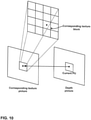
- FIG. 7 is a conceptual diagram illustrating depth block derivation from a reference view to perform BVSP.
- FIG. 7 illuminates the three steps how a depth block from the reference view is located and then used for BVSP prediction.
- the video coder may further refine the disparity vector using one or more of the methods described elsewhere in this disclosure.
- the video coder may treat the BVSP mode described above as a special inter-coded mode and the video coder may maintain a flag of indicating the usage of BVSP mode for each PU. Rather than signaling the flag in the bit stream, the video coder may add a new merging candidate (BVSP merging candidate) to a merge candidate list and the flag is dependent on whether a decoded merge candidate index corresponds to a BVSP merging candidate.
- the BVSP merging candidate is defined as follows:
- the insertion position of a BVSP merging candidate is dependent on the spatial neighboring blocks. For example, if any of the five spatial neighboring blocks (A 0 , A 1 , B 0 , B 1 or B 2 ) is coded with the BVSP mode, i.e., the maintained flag of the neighboring block is equal to 1, the video coder may treat the BVSP merging candidate as the corresponding spatial merging candidate and may insert the BVSP merging candidate into the merge candidate list. The video coder may only insert the BVSP merging candidate into the merge candidate list once.
- the video coder may insert the BVSP merging candidate into the merge candidate list immediate before any temporal merging candidates.
- the video coder may check additional conditions to avoid including the BVSP merging candidate.
- the video coder may further partition the BVSP into several sub-regions with the size equal to KxK (wherein K may be 4 or 2).
- the size of the BVSP-coded PU may be denoted by NxM.
- the video coder may derive a separate disparity motion vector.
- the video coder may predict each sub-region from one block located by the derived disparity motion vector in the inter-view reference picture.
- the size of motion-compensation unit for BVSP coded PUs are set to KxK. In some test conditions, K is set to 4.
- the video coder may perform the following disparity motion vector derivation process. For each sub-region (4x4 block) within one PU coded with BVSP mode, the video coder may firstly locate a corresponding 4x4 depth block in the reference depth view with the refined disparity vector mentioned above. Secondly, the video coder may select the maximum value of the sixteen depth pixels in the corresponding depth block. Thirdly, the video coder may convert the maximum value to the horizontal component of a disparity motion vector. The video coder may set the vertical component of the disparity motion vector to 0.
- the video coder may add a new motion vector candidate (i.e., an Inter-view Predicted Motion Vector Candidate (IPMVC)), if available, to AMVP and skip/merge modes.
- IPMVC Inter-view Predicted Motion Vector Candidate
- the IPMVC if available, is a temporal motion vector. Since skip mode has the same motion vector derivation process as merge mode, techniques described in this document may apply to both merge and skip modes.
- the IPMVC may be derived by the following steps. First, the video coder may locate, using the disparity vector, a corresponding block of the current block (e.g., a PU, a CU, etc.) in a reference view of the same access unit. Second, if the corresponding block is not intra-coded and not inter-view predicted and a reference picture of the corresponding block has a POC value equal to that of one entry in the same reference picture list of the current block, the video coder may convert the reference index of the corresponding block based on POC values. Furthermore, the video coder may derive the IPMVC to specify the prediction direction of the corresponding block, the motion vectors of the corresponding block, and the converted reference indices.
- the video coder may derive the IPMVC to specify the prediction direction of the corresponding block, the motion vectors of the corresponding block, and the converted reference indices.
- Section H.8.5.2.1.10 of 3D-HEVC Test Model 4 describes a derivation process for a temporal inter-view motion vector candidate.
- An IPMVC may be referred to as a temporal inter-view motion vector candidate because it indicates a location in a temporal reference picture.
- ( xP, yP ) denotes coordinates of a top-left luma sample of the current PU relative to a top-left luma sample of the current picture
- nPSW and nPSH denote the width and height of the current prediction unit, respectively
- refViewIdx denotes a reference view order index
- mvDisp denotes a disparity vector.
- the corresponding block is set to a PU that covers the luma location ( xRef, yRef ) in a view component with Viewldx equal to refViewIdx.
- the Clip3 function may be defined as:
- FIG. 8 is a conceptual diagram illustrating an example derivation of an IPMVC for merge/skip mode.
- FIG. 8 shows an example of the derivation process of the inter-view predicted motion vector candidate.
- a current PU 50 occurs in view VI at a time instance T1.
- a reference PU 52 for current PU 50 occurs in a different view than current PU 50 (i.e., view VO) and at the same time instance as current PU (i.e., time instance T1).
- reference PU 52 is bi-directionally inter predicted.
- reference PU 52 has a first motion vector 54 and a second motion vector 56.
- Motion vector 54 indicates a position in a reference picture 58.
- Reference picture 58 occurs in view VO and in time instance TO.
- Motion vector 56 indicates a position in reference picture 60.
- Reference picture 60 occurs in view VO and in time instance T3.
- the video coder may generate, based on the motion information of reference PU 52, an IPMVC for inclusion in a merge candidate list of current PU 50.
- the IPMVC may have a first motion vector 62 and a second motion vector 64.
- Motion vector 62 matches motion vector 54 and motion vector 64 matches motion vector 56.
- the video coder generates the IPMVC such that a first reference index of the IPMVC indicates a position in RefPicListO for current PU 50 of a reference picture (i.e., reference picture 66) occurring in the same time instance as reference picture 58 (i.e., time instance TO).
- reference picture 66 occurs in the first position (i.e., Ref0) in RefPicListO for current PU 50.
- the video coder generates the IPMVC such that a second reference index of the IPMVC indicates a position in RefPicList1 for current PU 50 of a reference picture (i.e., reference picture 68) occurring in the same time instance as reference picture 60.
- the RefPicListO reference index of the IPMVC may be equal to 0.
- a reference picture 70 occurs in the first position (i.e., RefO) in RefPicList1 for current PU 50 and reference picture 68 occurs in the second position (i.e., Ref1) in RefPicList1 for current PU 50.
- the RefPicList1 reference index of the IPMVC may be equal to 1.
- the video coder may convert the disparity vector for the current PU into an inter-view disparity motion vector (IDMVC) and may include the IDMVC in a merge candidate list for the current PU.
- IDMVC inter-view disparity motion vector
- the disparity vector may be converted to an IDMVC, which is added into a merge candidate list in a different position from an IPMVC, or added into the AMVP candidate list in the same position as the IPMVC when the IDMVC is available.
- IPMVC or IDMVC is called 'inter-view candidate' in this context.
- the term "inter-view candidate" may be used to refer to either an IPMVC or an IDMVC.
- the video coder in the merge/skip mode, the video coder always inserts an IPMVC, if available, into the merge candidate list before all spatial and temporal merging candidates. Furthermore, the video coder may insert the IDMVC before the spatial merging candidate derived from A 0 .
- a video coder may derive a disparity vector with the method of DoNBDV.
- the merging candidate list construction process in 3D-HEVC can be defined as follows:
- section 8.5.3.2.3 of HEVC Working Draft 10 defines an example use of 10CandIdx and 11CandIdx in deriving combined bi-predictive merging candidates. Section 8.5.3.2.3 of HEVC Working Draft 10 is reproduced below.
- variable numOrigMergeCand is greater than 1 and less than MaxNumMergeCand
- the variable numInputMergeCand is set equal to numCurrMergeCand
- the variable combldx is set equal to 0
- the variable combStop is set equal to FALSE, and the following steps are repeated until combStop is equal to TRUE: 1.
- the variables 10CandIdx and 11CandIdx are derived using combldx as specified in Table 8-6. 2.
- the following assignments are made, with l0Cand being the candidate at position 10CandIdx and 11Cand being the candidate at position 11CandIdx in the merging candidate list mergeCandList:
- Motion vector inheritance exploits the similarity of the motion characteristics between the texture images and its associated depth images.
- a video coder may include an MVI candidate in a merge candidate list.
- the MVI candidate reuses using the motion vectors and reference indices of the already coded corresponding texture block, if it is available.
- FIG. 10 is a conceptual diagram illustrating an example derivation of a motion vector inheritance candidate for depth coding.
- FIG. 10 shows an example of the derivation process of the MVI candidate where the corresponding texture block is selected as the 4x4 block located to the right bottom of the center of the current PU.
- motion vectors with integer precision are used in depth coding while quarter precision of motion vectors is utilized for texture coding. Therefore, the motion vector of the corresponding texture block may be scaled before using as a MVI candidate.
- the merge candidate list for the depth views may be constructed as follows:
- ARP Advanced residual prediction
- CUs with partition mode equal to Part_2Nx2N was adopted in the 4 th JCT3V meeting, as proposed in Zhang et al., "CE4: Advanced Residual Prediction for Multiview Coding," Joint Collaborative Team on 3D Video Coding Extensions of ITU-T SG 16 WP 3 and ISO/IEC JTC 1/SC 29/WG 11, 4th Meeting: Incheon, KR, 20-26 Apr.
- JCT3V-D0177 document JCT3V-D0177, which as of December 17, 2013 , is available from http://phenix.it-sudparis.eu/jct3v/doc_end_user/documents/4_Incheon/wg11/JCT3V-D0177-v2.zip (hereinafter JCT3V-D0177).
- FIG. 11 illustrates an example prediction structure of ARP in multi-view video coding. As shown in FIG. 11 , the video coder may invoke the following blocks in the prediction of a current block.
- the residual predictor is denoted as BaseTRef-Base, wherein the subtraction operation applies to each pixel of the denoted pixel arrays.
- the video coder may multiply a weighting factor w to the residual predictor. Therefore, the final predictor of the current block may be denoted as: CurrTRef+ w ⁇ (BaseTRef-Base).
- FIG. 11 are both based on the assumption that uni-directional prediction is applied.
- the above steps are applied for each reference picture list.
- the current block uses an inter-view reference picture (in a different view) for one reference picture list, the residual prediction process is disabled.
- the video coder may obtain a disparity vector as specified in 3D-HEVC Working Draft 4, pointing to a target reference view. Then, in the picture of the reference view within the same access unit as the current picture, the video coder may use the disparity vector to locate the corresponding block. Next, the video coder may re-use the motion information of the current block to derive the motion information for the reference block. The video coder may then apply motion compensation for the corresponding block based the same motion vector of current block and derived reference picture in the reference view for the reference block, to derive a residue block.
- FIG. 12 shows the relationship among the current block, the corresponding block and the motion compensated block. In other words, FIG.
- FIG. 12 is a conceptual diagram illustrating an example relationship among a current block, a reference block, and motion compensated blocks.
- the reference picture in the reference view (V 0 ) which has the same POC (Picture Order Count) value as the reference picture of current view (V m ) is selected as the reference picture of the corresponding block.
- the video coder may apply the weighting factor to the residue block to determine a weighted residue block.
- the video coder may add the values of the weighted residue block to the predicted samples.
- Video encoder 20 may select the weighting factor leading to minimal rate-distortion cost for the current CU as the final weighting factor. Video encoder 20 may signal the corresponding weighting factor index (0, 1 and 2 which correspond to weighting factor 0, 1, and 0.5, respectively) in the bitstream at the CU level. All PU predictions in a CU may share the same weighting factor. When the weighting factor is equal to 0, the video coder does not use ARP for the current CU.
- JCT3V-C0049 the reference pictures of PUs coded with non-zero weighting factors may be different from block to block. Therefore, the video coder may need to access different pictures from the reference view to generate the motion-compensated block (i.e., BaseTRef in the example of FIG. 11 ) of the corresponding block.
- the video coder may scale the decoded motion vectors of the current PU towards a fixed picture before performing motion compensation for the residual generation process, when the weighting factor is unequal to 0.
- the fixed picture is defined as the first reference picture of each reference picture list if it is from the same view.
- the video coder may first scale the decoded motion vector and then use the scaled motion vector to identify CurrTRef and BaseTRef.
- Such a reference picture used for ARP may be referred to as the target ARP reference picture.
- the video coder may apply a bi-linear filter during the interpolation process of the corresponding block and a prediction block of the corresponding block. While for the prediction block of the current PU in the non-base views, the video coder may apply a conventional 8/4-tap filter. JCT3V-D0177 proposes always employing bi-linear regardless of whether the block is in base view or non-base view when ARP is applied.
- the video coder may identify the reference view by the view order index returned from the NBDV derivation process.
- ARP is disabled for this reference picture list.
- a disparity vector is converted by an estimated depth value from the neighboring samples of the current block. Furthermore, more merge candidates can be derived e.g., by accessing the reference block of the base view identified by a disparity vector.
- a video coder may identify a reference 4x4 block by two steps.
- the first step is to identify a pixel with a disparity motion vector.
- the second step is to get the 4x4 block (with a unique set of motion information corresponding to RefPicListO or RefPicList1 respectively) and utilize the motion information to create a merge candidate.
- JCT3V-E0184 proposes a sub-PU level inter-view motion prediction method for the temporal inter-view merge candidate (i.e., the candidate derived from a reference block in the reference view).
- the basic concept of inter-view motion prediction is described elsewhere in this disclosure. In the basic concept of inter-view motion prediction, only the motion information of the reference block is used for the current PU in the dependent view.
- FIG. 13 is a conceptual diagram illustrating an example of sub-PU inter-view motion prediction.
- the temporal inter-view merge candidate may be derived as follows.
- the assigned sub-PU size may be denoted as NxN.
- Different sub-PU block sizes may be applied, for example, 4x4, 8x8, and 16x16.
- the video coder may first divide the current PU into multiple sub-PUs, each of which has a smaller size than the current PU.
- the size of the current PU may be denoted by nPSW x nPSH.
- the sizes of the sub-PUs may be denoted by nPSWsub x nPSHSub.
- nPSWsub and nPSHsub may be related to nPSW and nSPH as shown in the following equations.
- the video coder may set a default motion vector tmvLX to (0, 0) and may set a reference index refLX to -1 (with X being 0 or 1) for each reference picture list.
- the video coder may apply the following actions for each sub-PU in the raster scan order. First, the video coder may add the disparity vector to a middle position of the current sub-PU (whose top-left sample location is (xPSub, yPSub)) to obtain a reference sample location (xRefSub, yRefSub).
- the video coder may use a block in the reference view that covers (xRefSub, yRefSub) as the reference block for the current sub-PU.
- the motion information of the reference block is inherited by all the previous sub-PUs. Furthermore, if the identified reference block is coded using temporal motion vectors, the associated motion parameters can be used as motion parameters for the current sub-PU. In addition, if the identified reference block is coded using temporal motion vectors, the video coder may update tmvLX and refLX to the motion information of the current sub-PU. Otherwise, if the reference block is intra coded, the video coder may set the motion information of the current sub-PU to tmvLX and refLX.
- the sub-PU motion prediction method as proposed in JCT3V-E0184 has one or more problems. For example, when the corresponding block of one sub-PU in a reference view is intra coded (i.e., its motion information is unavailable), the motion information of the nearest sub-PU in the raster scan order is copied to the current sub-PU. Therefore, if the corresponding blocks of the first N sub-PUs in the raster scan order are intra coded and the corresponding block of the (N+1)-th sub-PU is inter coded, the related motion information set to the (N+1)-th sub-PU shall be copied to the first N sub-PUs which causes additional complexity and coding delay.
- One or more examples of this disclosure relate to inter-view motion prediction. For instance, one or more example of this disclosure are applicable in the context when the merge index indicates inter-view motion prediction.
- a video coder when a video coder uses inter-view motion prediction in a sub-PU fashion, if a current sub-PU for which the motion information is unavailable, a video coder may copy the motion information from default motion vectors and reference indices. For instance, if the motion information for the current sub-PU is unavailable, a video coder may copy the motion information for the current sub-PU from default motion vectors and default reference indices.
- the default motion parameters are the same for each sub-PU in the plurality of sub-PUs, regardless of whether there are subsequently sub-PUs having reference blocks that are coded using motion compensated prediction.
- a video coder may divide a current PU into a plurality of sub-PUs.
- the current PU is in a current picture.
- the video coder may determine default motion parameters.
- the default motion parameters may include one or more default motion vectors and one or more default reference indices.
- the video coder may process sub-PUs from the plurality of sub-PUs in a particular order. For each respective sub-PU from the plurality of sub-PUs, the video coder may determine a reference block for the respective sub-PU.
- the reference picture may be in a different view than the current picture and the video coder may determine, based on a disparity vector of the current PU, a reference sample location in the reference picture.
- the reference block for the respective sub-PU may cover the reference sample location.
- the current picture is a depth view component and the reference picture is a texture view component that is in the same view and access unit as the current picture.
- the video coder may determine that the reference block for the respective sub-PU is a PU of the reference picture that is co-located with the respective sub-PU.
- the video coder may set motion parameters of the respective sub-PU based on motion parameters of the reference block for the respective sub-PU.
- the video coder may set the motion parameters of the respective sub-PU to the default motion parameters.
- the motion parameters of the respective sub-PU are not set in response to a subsequent determination that a reference block for any later sub-PU in the order is coded using motion compensated prediction.
- the video coder may not need to scan forward to find a sub-PU whose corresponding reference block is coded using motion compensated prediction.
- the video coder may not need to delay determining the motion parameters of the respective sub-PU until the video coder encounters, during the processing of the sub-PUs, a PU whose corresponding reference block is coded using motion compensated prediction.
- this may decrease complexity and coding delay.
- the video coder may include a candidate in a candidate list of the current PU, wherein the candidate is based on the motion parameters of the plurality of sub-PUs.
- the candidate list is a merge candidate list.
- the video coder is a video encoder (e.g., video encoder 20)
- the video encoder may signal, in a bitstream, a syntax element (e.g., merge_idx) that indicates a selected candidate in the candidate list.
- the video coder is a video decoder (e.g., video decoder 30)
- the video decoder may obtain, from a bitstream, a syntax element (e.g., merge_idx) that indicates a selected candidate in the candidate list.
- the video decoder may use motion parameters of the selected candidate to reconstruct a predictive block for the current PU.
- FIG. 14 is a block diagram illustrating an example video encoder 20 that may implement the techniques of this disclosure.
- FIG. 14 is provided for purposes of explanation and should not be considered limiting of the techniques as broadly exemplified and described in this disclosure.
- this disclosure describes video encoder 20 in the context of HEVC coding.
- the techniques of this disclosure may be applicable to other coding standards or methods.
- video encoder 20 includes a prediction processing unit 100, a residual generation unit 102, a transform processing unit 104, a quantization unit 106, an inverse quantization unit 108, an inverse transform processing unit 110, a reconstruction unit 112, a filter unit 114, a decoded picture buffer 116, and an entropy encoding unit 118.
- Prediction processing unit 100 includes an inter-prediction processing unit 120 and an intra-prediction processing unit 126.
- Inter-prediction processing unit 120 includes a motion estimation unit 122 and a motion compensation unit 124.
- video encoder 20 may include more, fewer, or different functional components.
- Video encoder 20 may receive video data. Video encoder 20 may encode each CTU in a slice of a picture of the video data. Each of the CTUs may be associated with equally-sized luma coding tree blocks (CTBs) and corresponding CTBs of the picture. As part of encoding a CTU, prediction processing unit 100 may perform quad-tree partitioning to divide the CTBs of the CTU into progressively-smaller blocks. The smaller blocks may be coding blocks of CUs. For example, prediction processing unit 100 may partition a CTB associated with a CTU into four equally-sized sub-blocks, partition one or more of the sub-blocks into four equally-sized sub-sub-blocks, and so on.
- CTBs luma coding tree blocks
- Video encoder 20 may encode CUs of a CTU to generate encoded representations of the CUs (i.e., coded CUs).
- prediction processing unit 100 may partition the coding blocks associated with the CU among one or more PUs of the CU.
- each PU may be associated with a luma prediction block and corresponding chroma prediction blocks.
- Video encoder 20 and video decoder 30 may support PUs having various sizes. As indicated above, the size of a CU may refer to the size of the luma coding block of the CU and the size of a PU may refer to the size of a luma prediction block of the PU.
- video encoder 20 and video decoder 30 may support PU sizes of 2Nx2N or NxN for intra prediction, and symmetric PU sizes of 2Nx2N, 2NxN, Nx2N, NxN, or similar for inter prediction.
- Video encoder 20 and video decoder 30 may also support asymmetric partitioning for PU sizes of 2NxnU, 2NxnD, nLx2N, and nRx2N for inter prediction.
- Inter-prediction processing unit 120 may generate predictive data for a PU by performing inter prediction on each PU of a CU.
- the predictive data for the PU may include predictive blocks of the PU and motion information for the PU.
- Inter-prediction processing unit 120 may perform different operations for a PU of a CU depending on whether the PU is in an I slice, a P slice, or a B slice. In an I slice, all PUs are intra predicted. Hence, if the PU is in an I slice, inter-prediction processing unit 120 does not perform inter prediction on the PU.
- motion estimation unit 122 may search the reference pictures in a list of reference pictures (e.g., "RefPicListO") for a reference region for the PU.
- the reference region for the PU may be a region, within a reference picture, that contains samples that most closely correspond to the prediction blocks of the PU.
- Motion estimation unit 122 may generate a reference index that indicates a position in RefPicListO of the reference picture containing the reference region for the PU.
- motion estimation unit 122 may generate a motion vector that indicates a spatial displacement between a coding block of the PU and a reference location associated with the reference region.
- the motion vector may be a two-dimensional vector that provides an offset from the coordinates in the current picture to coordinates in a reference picture.
- Motion estimation unit 122 may output the reference index and the motion vector as the motion information of the PU.
- Motion compensation unit 124 may generate the predictive blocks of the PU based on actual or interpolated samples at the reference location indicated by the motion vector of the PU.
- motion estimation unit 122 may perform uni-prediction or bi-prediction for the PU. To perform uni-prediction for the PU, motion estimation unit 122 may search the reference pictures of RefPicListO or a second reference picture list ("RefPicList1") for a reference region for the PU.
- RefPicListO a second reference picture list
- Motion estimation unit 122 may output, as the motion information of the PU, a reference index that indicates a position in RefPicListO or RefPicList1 of the reference picture that contains the reference region, a motion vector that indicates a spatial displacement between a prediction block of the PU and a reference location associated with the reference region, and one or more prediction direction indicators that indicate whether the reference picture is in RefPicListO or RefPicList1.
- Motion compensation unit 124 may generate the predictive blocks of the PU based at least in part on actual or interpolated samples at the reference location indicated by the motion vector of the PU.
- motion estimation unit 122 may search the reference pictures in RefPicListO for a reference region for the PU and may also search the reference pictures in RefPicList1 for another reference region for the PU.
- Motion estimation unit 122 may generate reference indexes that indicate positions in RefPicListO and RefPicList1 of the reference pictures that contain the reference regions.
- motion estimation unit 122 may generate motion vectors that indicate spatial displacements between the reference locations associated with the reference regions and a prediction block of the PU.
- the motion information of the PU may include the reference indexes and the motion vectors of the PU.
- Motion compensation unit 124 may generate the predictive blocks of the PU based at least in part on actual or interpolated samples at the reference locations indicated by the motion vectors of the PU.
- motion estimation unit 122 may generate a merge candidate list for the PU. As part of generating the merge candidate list, motion estimation unit 122 may determine an IPMVC and/or a texture merge candidate. When determining the IPMVC and/or the texture merge candidate, motion estimation unit 122 may partition the PU into sub-PUs and process the sub-PUs according to a particular order to determine motion parameters for the sub-PUs. In accordance with one or more techniques of this disclosure, if a reference block for a respective sub-PU is not coded using motion compensated prediction, motion estimation unit 122 does not set the motion parameters of the respective sub-PU in response to a subsequent determination that a reference block for any later sub-PU in the particular order is coded using motion compensated prediction.
- motion estimation unit 122 may set to motion parameters of the respective sub-PU to default motion parameters. If the IPMVC or the texture merge candidate is the selected merge candidate in the merge candidate list, motion compensation unit 124 may determine a predictive block for the respective PU based on motion parameters specified by the IPMVC or the texture merge candidate.
- Intra-prediction processing unit 126 may generate predictive data for a PU by performing intra prediction on the PU.
- the predictive data for the PU may include predictive blocks for the PU and various syntax elements.
- Intra-prediction processing unit 126 may perform intra prediction on PUs in I slices, P slices, and B slices.
- intra-prediction processing unit 126 may use multiple intra prediction modes to generate multiple sets of predictive blocks for the PU.
- intra-prediction processing unit 126 may generate predictive blocks for the PU using a particular set of samples from neighboring blocks.
- the neighboring blocks may be above, above and to the right, above and to the left, or to the left of the prediction blocks of the PU, assuming a left-to-right, top-to-bottom encoding order for PUs, CUs, and CTUs.
- Intra-prediction processing unit 126 may use various numbers of intra prediction modes, e.g., 33 directional intra prediction modes. In some examples, the number of intra prediction modes may depend on the size of the prediction blocks of the PU.
- Prediction processing unit 100 may select the predictive data for PUs of a CU from among the predictive data generated by inter-prediction processing unit 120 for the PUs or the predictive data generated by intra-prediction processing unit 126 for the PUs. In some examples, prediction processing unit 100 selects the predictive data for the PUs of the CU based on rate/distortion metrics of the sets of predictive data. The predictive blocks of the selected predictive data may be referred to herein as the selected predictive blocks.
- Residual generation unit 102 may generate, based on the luma, Cb and Cr coding block of a CU and the selected predictive luma, Cb and Cr blocks of the PUs of the CU, luma, Cb and Cr residual blocks of the CU. For instance, residual generation unit 102 may generate the residual blocks of the CU such that each sample in the residual blocks has a value equal to a difference between a sample in a coding block of the CU and a corresponding sample in a corresponding selected predictive block of a PU of the CU.
- Transform processing unit 104 may perform quad-tree partitioning to partition the residual blocks of a CU into transform blocks associated with TUs of the CU.
- a TU may be associated with a luma transform block and two corresponding chroma transform blocks.
- the sizes and positions of the luma and chroma transform blocks of TUs of a CU may or may not be based on the sizes and positions of prediction blocks of the PUs of the CU.
- Transform processing unit 104 may generate transform coefficient blocks for each TU of a CU by applying one or more transforms to the transform blocks of the TU. Transform processing unit 104 may apply various transforms to a transform block associated with a TU. For example, transform processing unit 104 may apply a discrete cosine transform (DCT), a directional transform, or a conceptually-similar transform to a transform block. In some examples, transform processing unit 104 does not apply transforms to a transform block. In such examples, the transform block may be treated as a transform coefficient block.
- DCT discrete cosine transform
- Quantization unit 106 may quantize the transform coefficients in a coefficient block. The quantization process may reduce the bit depth associated with some or all of the transform coefficients. For example, an n-bit transform coefficient may be rounded down to an m-bit transform coefficient during quantization, where n is greater than m.
- Quantization unit 106 may quantize a coefficient block associated with a TU of a CU based on a quantization parameter (QP) value associated with the CU.
- QP quantization parameter
- Video encoder 20 may adjust the degree of quantization applied to the coefficient blocks associated with a CU by adjusting the QP value associated with the CU. Quantization may introduce loss of information, thus quantized transform coefficients may have lower precision than the original ones.
- Inverse quantization unit 108 and inverse transform processing unit 110 may apply inverse quantization and inverse transforms to a coefficient block, respectively, to reconstruct a residual block from the coefficient block.
- Reconstruction unit 112 may add the reconstructed residual block to corresponding samples from one or more predictive blocks generated by prediction processing unit 100 to produce a reconstructed transform block associated with a TU. By reconstructing transform blocks for each TU of a CU in this way, video encoder 20 may reconstruct the coding blocks of the CU.
- Filter unit 114 may perform one or more deblocking operations to reduce blocking artifacts in the coding blocks associated with a CU.
- Decoded picture buffer 116 may store the reconstructed coding blocks after filter unit 114 performs the one or more deblocking operations on the reconstructed coding blocks.
- Inter-prediction processing unit 120 may use a reference picture that contains the reconstructed coding blocks to perform inter prediction on PUs of other pictures.
- intra-prediction processing unit 126 may use reconstructed coding blocks in decoded picture buffer 116 to perform intra prediction on other PUs in the same picture as the CU.
- Entropy encoding unit 118 may receive data from other functional components of video encoder 20. For example, entropy encoding unit 118 may receive coefficient blocks from quantization unit 106 and may receive syntax elements from prediction processing unit 100. Entropy encoding unit 118 may perform one or more entropy encoding operations on the data to generate entropy-encoded data.
- entropy encoding unit 118 may perform a context-adaptive variable length coding (CAVLC) operation, a CABAC operation, a variable-to-variable (V2V) length coding operation, a syntax-based context-adaptive binary arithmetic coding (SBAC) operation, a Probability Interval Partitioning Entropy (PIPE) coding operation, an Exponential-Golomb encoding operation, or another type of entropy encoding operation on the data.
- Video encoder 20 may output a bitstream that includes entropy-encoded data generated by entropy encoding unit 118.
- FIG. 15 is a block diagram illustrating an example video decoder 30 that may implement the techniques of this disclosure.
- FIG. 15 is provided for purposes of explanation and is not limiting on the techniques as broadly exemplified and described in this disclosure.
- this disclosure describes video decoder 30 in the context of HEVC coding.
- the techniques of this disclosure may be applicable to other coding standards or methods.
- video decoder 30 includes an entropy decoding unit 150, a prediction processing unit 152, an inverse quantization unit 154, an inverse transform processing unit 156, a reconstruction unit 158, a filter unit 160, and a decoded picture buffer 162.
- Prediction processing unit 152 includes a motion compensation unit 164 and an intra-prediction processing unit 166.
- video decoder 30 may include more, fewer, or different functional components.
- a coded picture buffer (CPB) 151 may receive and store encoded video data (e.g., NAL units) of a bitstream.
- Entropy decoding unit 150 may receive NAL units from CPB 151 and parse the NAL units to obtain syntax elements from the bitstream.
- Entropy decoding unit 150 may entropy decode entropy-encoded syntax elements in the NAL units.
- Prediction processing unit 152, inverse quantization unit 154, inverse transform processing unit 156, reconstruction unit 158, and filter unit 160 may generate decoded video data based on the syntax elements extracted from the bitstream.
- the NAL units of the bitstream may include coded slice NAL units.
- entropy decoding unit 150 may extract and entropy decode syntax elements from the coded slice NAL units.
- Each of the coded slices may include a slice header and slice data.
- the slice header may contain syntax elements pertaining to a slice.
- video decoder 30 may perform a decoding operation on a CU. By performing the decoding operation on a CU, video decoder 30 may reconstruct coding blocks of the CU.
- inverse quantization unit 154 may inverse quantize, i.e., de-quantize, coefficient blocks associated with TUs of the CU.
- Inverse quantization unit 154 may use a QP value associated with the CU of the TU to determine a degree of quantization and, likewise, a degree of inverse quantization for inverse quantization unit 154 to apply. That is, the compression ratio, i.e., the ratio of the number of bits used to represent original sequence and the compressed one, may be controlled by adjusting the value of the QP used when quantizing transform coefficients.
- the compression ratio may also depend on the method of entropy coding employed.
- inverse transform processing unit 156 may apply one or more inverse transforms to the coefficient block in order to generate a residual block associated with the TU.
- inverse transform processing unit 156 may apply an inverse DCT, an inverse integer transform, an inverse Karhunen-Loeve transform (KLT), an inverse rotational transform, an inverse directional transform, or another inverse transform to the coefficient block.
- KLT Karhunen-Loeve transform
- intra-prediction processing unit 166 may perform intra prediction to generate predictive blocks for the PU.
- Intra-prediction processing unit 166 may use an intra prediction mode to generate the predictive luma, Cb, and Cr blocks for the PU based on the prediction blocks of spatially-neighboring PUs.
- Intra-prediction processing unit 166 may determine the intra prediction mode for the PU based on one or more syntax elements decoded from the bitstream.
- Prediction processing unit 152 may construct a first reference picture list (RefPicListO) and a second reference picture list (RefPicList1) based on syntax elements extracted from the bitstream. Furthermore, if a PU is encoded using inter prediction, entropy decoding unit 150 may obtain motion information for the PU. Motion compensation unit 164 may determine, based on the motion information of the PU, one or more reference regions for the PU. Motion compensation unit 164 may generate, based on samples at the one or more reference blocks for the PU, predictive luma, Cb, and Cr blocks for the PU.
- RefPicListO first reference picture list
- RefPicList1 second reference picture list
- motion compensation unit 164 may generate a merge candidate list for the PU. As part of generating the merge candidate list, motion compensation unit 164 may determine an IPMVC and/or a texture merge candidate. When determining the IPMVC and/or the texture merge candidate, motion compensation unit 164 may partition the PU into sub-PUs and process the sub-PUs according to a particular order to determine motion parameters for each of the sub-PUs. In accordance with one or more techniques of this disclosure, if a reference block for a respective sub-PU is not coded using motion compensated prediction, motion compensation unit 164 does not set the motion parameters of the respective sub-PU in response to a subsequent determination that a reference block for any later sub-PU in the particular order is coded using motion compensated prediction.
- motion compensation unit 164 may set to motion parameters of the respective sub-PU to default motion parameters. If the IPMVC or the texture merge candidate is the selected merge candidate in the merge candidate list, motion compensation unit 164 may determine a predictive block for the respective PU based on motion parameters specified by the IPMVC or the texture merge candidate.
- Reconstruction unit 158 may use the residual values from the luma, Cb, and Cr transform blocks associated with TUs of a CU and the predictive luma, Cb, and Cr blocks of the PUs of the CU, i.e., either intra-prediction data or inter-prediction data, as applicable, to reconstruct the luma, Cb, and Cr coding blocks of the CU.
- reconstruction unit 158 may add samples of the luma, Cb, and Cr transform blocks to corresponding samples of the predictive luma, Cb, and Cr blocks to reconstruct the luma, Cb, and Cr coding blocks of the CU.
- Filter unit 160 may perform a deblocking operation to reduce blocking artifacts associated with the luma, Cb, and Cr coding blocks of the CU.
- Video decoder 30 may store the luma, Cb, and Cr coding blocks of the CU in decoded picture buffer 162.
- Decoded picture buffer 162 may provide reference pictures for subsequent motion compensation, intra prediction, and presentation on a display device, such as display device 32 of FIG. 1 .
- video decoder 30 may perform, based on the luma, Cb, and Cr blocks in decoded picture buffer 162, intra prediction or inter prediction operations on PUs of other CUs.
- video decoder 30 may extract, from the bitstream, transform coefficient levels of the significant luma coefficient block, inverse quantize the transform coefficient levels, apply a transform to the transform coefficient levels to generate a transform block, generate, based at least in part on the transform block, a coding block, and output the coding block for display.
- the video coder may use zero motion with reference picture index equal to 0 for reference picture list 0 and reference picture list 1 (if current slice is a B slice) as the PU-level predicted motion vector candidate.
- the video coder may then use the PU-level predicted motion vector candidate as motion of sub-PU whose corresponding reference block is either coded with intra prediction mode or coded with inter prediction mode but its reference picture is not included in the reference picture list of the current slice.
- Examples of this disclosure may change the sub-PU level inter-view motion prediction process (or derivation process for a sub prediction block temporal inter-view motion vector candidate) defined in 3D-HEVC Draft Text 2 (i.e., document JCT3V-F1001v2).
- 3D-HEVC Draft Text 2 i.e., document JCT3V-F1001v2
- text added to 3D-HEVC Draft Text 2 is underlined and text deleted from 3D-HEVC Draft Text 2 are italicized and enclosed in double square brackets.
- variable ivRefPic is set equal to the picture with ViewIdx equal to refViewIdx in the current access unit.
- FIG. 16A is a flowchart illustrating an example operation of video encoder 20 to encode a CU using inter prediction, in accordance with an example of this disclosure.
- video encoder 20 may generate a merge candidate list for a current PU of a current CU (200).
- video encoder 20 may generate the merge candidate list such that the merge candidate list includes a temporal inter-view merge candidate based on motion information for sub-PUs of the current PU.
- the current PU may be a depth PU and video encoder 20 may generate the merge candidate list such that the merge candidate list includes a texture merge candidate based on motion information for sub-PUs of the current depth PU.
- video encoder 20 may perform the operation of FIG. 17 to generate the merge candidate list for the current PU.
- video encoder 20 may select a merge candidate from the merge candidate list (202). In some examples, video encoder 20 may select the merge candidate based on a rate/distortion analysis. Furthermore, video encoder 20 may use the motion information (e.g., the motion vectors and reference indexes) of the selected merge candidate to determine predictive blocks for the current PU (204). Video encoder 20 may signal a merge candidate index that indicates a position within the merge candidate list of the selected merge candidate (206).
- motion information e.g., the motion vectors and reference indexes
- the selected merge candidate is an IPMVC or an MVI candidate (i.e., a texture merge candidate) constructed using sub-PUs as described in the examples of this disclosure
- the IPMVC or MVI candidate may specify a separate set of motion parameters (e.g., a set of one or more motion vectors and a set of one or more reference indexes) for each sub-PU of the current PU.
- video encoder 20 may use the motion parameters of the sub-PUs of the current PU to determine predictive blocks for the sub-PUs.
- Video encoder 20 may determine the predictive blocks for the current PU by assembling the predictive blocks for the sub-PUs of the current PU.
- Video encoder 20 may determine whether there are any remaining PUs in the current CU (208). If there are one or more remaining PUs in the current CU ("YES" of 208), video encoder 20 may repeat actions 200-208 with another PU of the current CU as the current PU. In this way, video encoder 20 may repeat actions 200-208 for each PU of the current CU.
- video encoder 20 may determine residual data for the current CU (210).
- each sample of the residual data may indicate a difference between a sample in a coding block of the current CU and a corresponding sample in a predictive block of a PU of the current CU.
- video encoder 20 may use ARP to determine the residual data for the current CU.
- Video encoder 20 may signal the residual data in a bitstream (212).
- video encoder 20 may signal the residual data in the bitstream by applying one or more transforms to the residual data to generate coefficient blocks, quantize the coefficients, entropy encode syntax elements indicating the quantized coefficients, and include the entropy encoded syntax elements in the bitstream.
- FIG. 16B is a flowchart illustrating an example operation of video decoder 30 to decode a CU using inter prediction, in accordance with an example of this disclosure.
- video decoder 30 may generate a merge candidate list for a current PU of a current CU (220).
- video decoder 30 may generate the merge candidate list such that the merge candidate list includes a temporal inter-view merge candidate based on motion information for sub-PUs of the current PU.
- the current PU may be a depth PU and video decoder 30 may generate the merge candidate list such that the merge candidate list includes a texture merge candidate based on motion information for sub-PUs of the current depth PU.
- video decoder 30 may perform the operation of FIG. 17 to generate the merge candidate list for the current PU.
- video decoder 30 may determine a selected merge candidate from the merge candidate list (222). In some examples, video decoder 30 may determine the selected merge candidate based on a merge candidate index signaled in the bitstream. Furthermore, video decoder 30 may use the motion parameters (e.g., the motion vectors and reference indexes) of the selected merge candidate to determine predictive blocks for the current PU (224). For instance, video decoder 30 may use the motion parameters of the selected merge candidate to determine a luma predictive block, a Cb predictive block, and a Cr predictive block for the current PU.
- motion parameters e.g., the motion vectors and reference indexes
- the IPMVC or MVI candidate may specify a separate set of motion parameters (e.g., a set of one or more motion vectors and a set of one or more reference indexes) for each sub-PU of the current PU.
- video decoder 30 may use the motion parameters of the sub-PUs of the current PU to determine predictive blocks for the sub-PUs.
- Video decoder 30 may determine the predictive blocks for the current PU by assembling the predictive blocks for the sub-PUs of the current PU.
- Video decoder 30 may then determine whether there are any remaining PUs in the current CU (226). If there are one or more remaining PUs in the current CU ("YES" of 226), video decoder 30 may repeat actions 220-226 with another PU of the current CU as the current PU. In this way, video decoder 30 may repeat actions 220-226 for each PU of the current CU.
- video decoder 30 may determine residual data for the current CU (228). In some examples, video decoder 30 may determine the residual data in parallel with determining the motion parameters of the PUs of the current CU. In some examples, video decoder 30 may use ARP to determine the residual data for the current CU. In addition, video decoder 30 may reconstruct the coding blocks of the current CU based on the predictive blocks for the PUs of the current CU and the residual data for the current CU (230).
- FIG. 17 is a flowchart illustrating an example operation of a video coder to construct a merge candidate list for a current PU in a current view component, in accordance with an example of this disclosure.
- the video coder e.g., video encoder 20 or video decoder 30
- the spatial merge candidates may include merge candidates that specify the motion parameters of PUs that cover locations A 0 , A 1 , B 0 , B 1 , and B 2 in FIG. 3 .
- the video coder may determine the spatial merge candidates by performing the operation described in subclause G.8.5.2.1.2 of MV-HEVC Test Model 4. Furthermore, in the example of FIG.
- the video coder may determine a temporal merging candidate (252).
- the temporal merging candidate may specify the motion parameters of a PU of a reference view component that is in a different time instance than the current view component.
- the video coder may determine the temporal merge candidate by performing the operation described in subclause H.8.5.2.1.7 of 3D-HEVC Test Model 4.
- the video coder may determine an IPMVC and an IDMVC (254).
- the video coder may generate the IPMVC using a sub-PU level inter-view motion prediction technique.
- the IPMVC may specify motion parameters of each sub-PU of the current PU.
- the video coder may perform the operation of FIG. 19 to determine the IPMVC.
- the IDMVC may specify the disparity vector for the current PU.
- the video coder only determines the IPMVC and the IDMVC when an inter-view motion prediction flag (e.g., iv_mv_pred_flag) for a current layer indicates that inter-view motion prediction is enabled for the current layer.
- the current layer may be the layer to which the current view component belongs.
- the video coder may determine a VSP merge candidate (256).
- the video coder may determine the VSP merge candidate by performing the operation described in subclause H.8.5.2.1.12 of 3D-HEVC Test Model 4.
- the video coder only determines the VSP merge candidate when a view synthesis prediction flag for the current layer indicates that view synthesis prediction is enabled for the current layer.
- the video coder may determine whether the current view component is a depth view component (258). Responsive to determining that the current view component is a depth view component ("YES" of 258), the video coder may determine a texture merge candidate (260).
- the texture merge candidate may specify the motion information of one or more PUs in a texture view component that corresponds to the current (depth) view component.
- the video coder may generate the texture merge candidate using a sub-PU level motion prediction technique.
- the texture merge candidate may specify motion parameters of each sub-PU of the current PU.
- the video coder may perform the operation of FIG. 19 to determine the texture merge candidate.
- the video coder may then determine whether the texture merge component is available (262). Responsive to determining that the texture merge component is available (“YES" of 262), the video coder may insert the texture merge candidate into the merge candidate list (264).
- the video coder may determine whether the IPMVC is available (266).
- the IPMVC may be unavailable when the video coder was unable to determine the IPMVC, such as when the current PU is in a base view. Responsive to determining that the IPMVC is available ("YES" of 268), the video coder may insert the IPMVC into the merge candidate list (268).
- the video coder may determine whether the spatial merge candidate for location A 1 (i.e., the A 1 spatial merge candidate) is available (270).
- a spatial merge candidate such as the A 1 spatial merge candidate, may be unavailable when a PU covering a location associated the spatial merge candidate (e.g., location A 0 , A 1 , B 0 , B 1 , or B 2 ) is coded using intra prediction or is outside a current slice or picture boundary.
- the video coder may determine whether the motion vectors and reference indices of the A 1 spatial merge candidate match representative motion vectors and representative reference indices of the IPMVC (270). Responsive to determining that the motion vectors and reference indices of the A 1 spatial merge candidate do not match the representative motion vectors and the representative reference indices of the IPMVC ("NO" of 272), the video coder may insert the A 1 spatial merge candidate into the merge candidate list (274).
- the video coder may generate the IPMVC and/or texture merge candidate using a sub-PU level motion prediction technique.
- the IPMVC and/or texture merge candidate may specify multiple motion vectors and multiple reference indices. Accordingly, the video coder may determine whether the motion vectors of the A 1 spatial merge candidate match representative motion vectors of the IPMVC and/or the texture merge candidate and whether the reference indices of the A 1 spatial merge candidate match representative reference indices of the IPMVC and/or texture merge candidate.
- the representative motion vectors and representative reference indices of the IPMVC may be referred to herein as a "PU-level IPMVC.”
- the representative motion vectors and representative reference indices of the texture merge candidate may be referred to herein as a "PU-level motion parameter inheritance (MPI) candidate.”
- MPI PU-level motion parameter inheritance
- the video coder may determine the PU-level IPMVC and PU-level MPI candidate in various ways. Examples of how the video coder may determine the PU-level IPMVC and PU-level MPI candidate are described elsewhere in this disclosure.
- the video coder may determine whether the spatial merge candidate for location B 1 (i.e., the B 1 spatial merge candidate) is available (276). Responsive to determining that the B 1 spatial merge candidate is available ("YES of 276), the video coder may determine whether motion vectors and reference indices of the B 1 spatial merge candidate match the representative motion vectors and the representative reference indices of the IPMVC (278).
- the video coder may include the B 1 spatial merge candidate in the merge candidate list (280).
- the video coder may determine whether the spatial merge candidate for location B 0 (i.e., the B 0 spatial merge candidate) is available (282). Responsive to determining that the B 0 spatial merge candidate is available ("YES" of 282), the video coder may insert the B 0 spatial merge candidate into the merge candidate list (284).
- the video coder may determine the representative motion vectors and representative reference indices of the IPMVC in various ways.
- the video coder may determine, from among the sub-PUs of the current PU, a center sub-PU.
- the center sub-PU is the closest sub-PU to a center pixel of a luma prediction block of the current PU. Because the height and/or width of a prediction block may be an even number of samples, a "center" pixel of a prediction block may be a pixel adjacent to a true center of the prediction block.
- the video coder may then determine an inter-view reference block for the center sub-PU by adding the disparity vector for the current PU to the coordinates of a center of a luma prediction block of the center sub-PU. If the inter-view reference block for the center sub-PU is coded using motion compensated prediction (i.e., the inter-view reference block for the center sub-PU has one or more motion vectors and reference indices), the video coder may set the motion information of the PU-level IPMVC to the motion information of the inter-view reference block for the center sub-PU.
- motion compensated prediction i.e., the inter-view reference block for the center sub-PU has one or more motion vectors and reference indices
- the PU-level IPMVC as provided by the center sub-PU, can be used for pruning this sub-PU candidate with other candidates, such as the spatial neighboring candidate A 1 and B 1 .
- the other conventional candidate is not added into the merge candidate list.
- the video coder may determine whether the IDMVC is available and the motion vector and reference index of the IDMVC are different than the motion vectors and reference indices of the A 1 spatial merge candidate and the B 1 spatial merge candidate (286). Responsive to determining that the IDMVC is available and the motion vector and reference index of the IDMVC are different than the motion vectors and reference indices of the A 1 spatial merge candidate and the B 1 spatial merge candidate ("YES" of 286), the video coder may insert the IDMVC into the merge candidate list (288).
- the video coder may perform the portion of the reference picture list construction operation shown in FIG. 18 (denoted in FIG. 17 as "A").
- FIG. 18 is a flowchart illustrating a continuation of the reference picture list construction operation of FIG. 17 , in accordance with an example of this disclosure.
- the video coder may determine whether the VSP merge candidate is available (300). Responsive to determining that the VSP merge candidate is available ("YES" of 300), the video coder may insert the VSP merge candidate into the merge candidate list (302).
- the video coder may determine whether the spatial merge candidate for location A 0 (i.e., the A 0 spatial merge candidate) is available (304). Responsive to determining that the A 0 spatial merge candidate is available ("YES" of 304), the video coder may insert the A 0 spatial merge candidate into the merge candidate list (306).
- the video coder may determine whether the spatial merge candidate for location B 2 (i.e., the B 2 spatial merge candidate) is available (308). Responsive to determining that the B 2 spatial merge candidate is available ("YES" of 308), the video coder may insert the B 2 spatial merge candidate into the merge candidate list (310).
- the video coder may determine whether the temporal merge candidate is available (312). Responsive to determining that the temporal merge candidate is available ("YES" of 312), the video coder may insert the temporal merge candidate into the merge candidate list (314).
- the video coder may determine whether the current slice is a B slice (316). Responsive to determining that the current slice is a B slice ("YES" of 316), the video coder may derive combined bi-predictive merge candidates (318). In some examples, the video coder may derive the combined bi-predictive merge candidates by performing the operation described in subclause H.8.5.2.1.3 of 3D-HEVC Test Model 4.
- the video coder may derive zero motion vector merge candidates (320).
- the zero motion vector merge candidates may specify motion vectors having horizontal and vertical components equal to 0.
- the video coder may derive the zero motion vector candidates by performing the operation described in subclause 8.5.2.1.4 of 3D-HEVC Test Model 4.
- FIG. 19 is a flowchart illustrating an operation of a video coder to determine an IPMVC or a texture merge candidate, in accordance with an example of this disclosure.
- the video coder e.g., video encoder 20 or video decoder 30
- the block size of each of the sub-PUs may be 4x4, 8x8, 16x16, or another size.
- the video coder may set a default motion vector and a default reference index (350).
- the video coder may set the default motion vector and the default reference index in various ways.
- the default motion parameters i.e., the default motion vectors and the default reference indices
- the video coder may determine the default motion information differently depending on whether the video coder is determining an IPMVC or a texture merge candidate.
- the video coder may derive a PU-level IPMVC from a center position of the corresponding region of the current PU, as defined in 3D-HEVC Test Model 4. Furthermore, in this example, the video coder may set the default motion vectors and reference indices equal to the PU-level IPMVC. For instance, the video coder may set the default motion vectors and the default reference indices to a PU-level IPMVC. In this instance, the video coder may derive the PU-level IPMVC from a center position of a corresponding region for the current PU.
- the video coder may set the default motion parameters to the motion parameters contained by an inter-view reference block covering a pixel at coordinates (xRef, yRef) of a reference picture in a reference view.
- (xP, yP) indicates the coordinates of the top-left sample of the current PU
- mvDisp is the disparity vector
- nPSWxnPSH is the size of the current PU
- PicWidthInSamplesL and PicHeightInSamplesL define the resolution of the picture in the reference view (same as the current view).
- the italicized text in double square brackets indicates text deleted
- section H.8.5.2.1.10 of 3D-HEVC Test Model 4 describes a derivation process for a temporal inter-view motion vector candidate. Furthermore, as discussed above, equations H-124 and H-125 are used in section H.8.5.2.1.10 of 3D-HEVC Test Model 4 to determine a luma location of a reference block in a reference picture. In contrast to equations H-124 and H-125 in 3D-HEVC Test Model 4, the equations of this example do not subtract 1 from nPSW and nPSH. As a result, xRef and yRef indicate the coordinates of a pixel immediately below and right of the true center of the prediction block of the current PU.
- the width and height of the prediction block of the current PU in sample values may be even numbers, there may not be a sample value at the true center of the prediction block of the current PU.
- a coding gain may result when xRef and yRef indicate the coordinates of a pixel immediately below and right of the true center of the prediction block of the current PU relative to when xRef and yRef indicate the coordinates of a pixel immediately above and left of the true center of the prediction block of the current PU.
- the video coder may use other blocks covering different pixels (xRef, yRef) to derive the default motion vectors and reference indices.
- the video coder may choose from among all the sub-PUs of the current PU, a sub-PU that is closest to a center pixel of a luma prediction block of the current PU.
- the video coder may then determine, for the chosen sub-PU, a reference block in a reference view component. In other words, the video coder may determine an inter-view reference block for the chosen sub-PU.
- the video coder may use the inter-view reference block for the chosen sub-PU to derive the default motion vectors and reference indices. In other words, the video coder may set the default motion parameters to the motion parameters of the sub-PU of the reference block that is closest to a center pixel of a luma prediction block of the current PU.
- the video coder may determine a reference block in the reference picture, the reference block having a same size as a prediction block of the current PU.
- the video coder may determine, from among sub-PUs of the reference block, a sub-PU that is closest to a center pixel of the reference block.
- the video coder may derive the default motion parameters from motion parameters of the determined sub-PU of the reference block.
- the video coder may determine the sub-PU that is closest to the center pixel of the reference block in various ways. For instance, assuming that the sub-PU size is 2 U ⁇ 2 U , the video coder may choose the sub-PU with the following coordinates relative to the top-left sample of the luma prediction block of the current PU: (((nPSW>>(u+1))-1)« u, (((nPSH>>(u+1))-1) ⁇ u).
- the sub-PU that is closest to the center pixel of the reference block includes a pixel having the following coordinates relative to a top-left sample of the reference block: (((nPSW>>(u+1))-1) ⁇ u, (((nPSH>>(u+1))-1) ⁇ u).
- the video coder may choose the sub-PU with the following coordinates relative coordinates relative to the top-left sample of the luma prediction block of the current PU ((nPSW>>(u+1)) ⁇ u, (nPSH>>(u+1)) ⁇ u).
- the sub-PU that is closest to the center pixel of the reference block includes a pixel having the following coordinates relative to a top-left sample of the reference block: ((nPSW>>(u+1)) ⁇ u, (nPSH>>(u+1)) ⁇ u).
- nPSW and nPSH are the width and height of the luma prediction block of the current PU, respectively.
- a video coder may determine, from among the plurality of sub-PUs of the current PU, a sub-PU that is closest to a center pixel of the luma prediction block of the current PU.
- the video coder may derive the default motion parameters from an inter-view reference block for the determined sub-PU.
- the default motion vector is a zero motion vector.
- the default reference index is equal to the first available temporal reference picture (i.e., a reference picture in a different time instance than the current picture) in a current reference picture list or the default reference index may be equal to 0.
- the default motion parameters may include a default motion vector and a default reference index.
- the video coder may set a default motion vector to a zero motion vector and may set the default reference index to 0 or a first available temporal reference picture in a current reference picture list.
- the default reference index may indicate a first available temporal reference picture in the current picture's RefPicListO (i.e., a temporal reference picture in the current picture's RefPicListO having a lowest reference index).
- the default reference index may indicate a first available temporal reference picture in the current picture's RefPicListO.
- the default reference index may indicate a first available temporal reference picture in the current picture's RefPicList1 (i.e., a temporal reference picture in the current picture's RefPicList1 having a lowest reference index).
- a default RefPicListO reference index may indicate a first available temporal reference picture in the current picture's RefPicListO and a default RefPicList1 reference index may indicate a first available temporal reference picture in the current picture's RefPicList1.
- the video coder may set the default motion parameters to the motion parameters of a sub-PU closest to a center pixel of the luma prediction block of the current PU.
- the default motion parameters may remain unavailable. For instance, if the inter-view reference block corresponding to the sub-PU closest to a center pixel of the luma prediction block of the current PU is intra predicted, the default motion parameters may remain unavailable.
- the video coder may set the default motion parameters to the motion parameters of the first sub-PU.
- the first sub-PU may be the first sub-PU of the current PU in a raster scan order of the sub-PUs of the current PU.
- the video coder may, in response to determining that the first sub-PU in a raster scan order of the plurality of sub-PUs has available motion parameters, set the default motion parameters to the available motion parameters of the first sub-PU in the raster scan order of the plurality of sub-PUs.
- the video coder may set the default motion information to the motion parameters of the first sub-PU of a current sub-PU row if the first sub-PU of the current sub-PU row has available motion parameters.
- the video coder may set the default motion vector to a zero motion vector and may set the default reference index equal to the first available temporal reference picture in the current reference picture list.
- the video coder when the video coder is determining the default motion parameters, the video coder may, in response to determining that the first sub-PU of a row of sub-PUs that includes the respective sub-PU has available motion parameters, set the default motion parameters to the available motion parameters of the first sub-PU of the row of sub-PUs that includes the respective sub-PU.
- the video coder may determine a texture merge candidate using a sub-PU level motion prediction technique.
- the current PU may be referred to herein as the "current depth PU.”
- the video coder may perform the operation of FIG. 19 to determine the texture merge candidate.
- the video coder may divide the current depth PU in several sub-PUs and each sub-PU uses the motion information of a co-located texture block for motion compensation.
- the video coder may assign the default motion vectors and reference indices to a sub-PU if the corresponding texture block of the sub-PU is intra coded or a picture in the same access unit as a reference picture of corresponding texture block is not included in a reference picture list of the current depth PU.
- the video coder may determine that a co-located texture block has available motion information when the co-located texture block is not intra coded and a reference picture used by the co-located texture block is in a reference picture list of the current depth picture.
- the motion parameters of a co-located texture block may be unavailable when the co-located texture block is intra coded or the co-located texture block uses a reference picture that is not in a reference picture list of the current depth picture.
- the video coder may determine the default motion information differently depending on whether the video coder is determining an IPMVC or a texture merge candidate. For instance, when the video coder is determining a texture merge candidate, the video coder may determine the default motion vectors and default reference indices according to one of the following examples or other examples.
- a co-located texture block may be co-located with the current depth PU and may have the same size as the current depth PU.
- the video coder sets the default motion vectors and default reference indices to the motion information of a block covering a center pixel of the co-located texture block.
- the video coder may set the default motion parameters to motion parameters associated with a block covering a pixel of a reference block that is in the reference picture, that is co-located with the current PU, and that has the same size as the current PU.
- the pixel may be a center pixel of the reference block or another pixel of the reference block.
- a co-located texture block may have the same size as the current depth PU.
- the video coder may set the default motion vectors and default reference indices to the motion information of a block (e.g., a PU) covering any given pixel within the co-located texture block.
- the video coder may firstly choose a center sub-PU of the current depth PU. Among all the sub-PUs of the current depth PU, the center sub-PU may be located closest to (or may include) a center pixel of the prediction block of the current depth PU. The video coder may then use a texture block co-located with the center sub-PU to derive the default motion vectors and reference indices.
- the video coder may determine that the center sub-PU is the sub-PU with the following coordinates relative to a top-left sample of the prediction block of the current depth PU (and hence, the top-left sample of a co-located texture block): (((nPSW>>(u+1))-1) ⁇ u, (((nPSH>>(u+1))-1) ⁇ u).
- the video coder may determine that the relative coordinates of the center sub-PU are: ((nPSW>>(u+1)) ⁇ u, (nPSH>>(u+1)) ⁇ u).In these equations, nPSW and nPSH are the width and height of the prediction block of the current depth PU, respectively.
- a video coder may determine, from among the plurality of sub-PUs of the current PU, a sub-PU that is closest to a center of a prediction block of the current PU.
- the video coder may derive the default motion parameters from a co-located texture block for the determined sub-PU.
- the video coder may determine whether a co-located texture block for a first sub-PU of the current depth PU has available motion information.
- the first sub-PU of the current depth PU may be the first sub-PU of the current depth PU in a raster scan order of the sub-PUs of the current depth PU. If the motion parameters of the co-located texture block for the first sub-PU of the current depth PU are available, the video coder may set the default motion parameters to the motion parameters of the first sub-PU of the current depth PU.
- the video coder when the default motion information is unavailable (e.g., when the motion parameters of the co-located texture block for the first sub-PU are unavailable), the video coder sets the default motion information to the motion information of a first sub-PU of a current sub-PU row if the first sub-PU of the current sub-PU row has available motion information. Furthermore, when the default motion information is unavailable (e.g., when the motion information of the first sub-PU of the current sub-PU row is unavailable), the default motion vector is a zero motion vector, and the default reference index is equal to the first available temporal reference picture in a current reference picture list or 0.
- the default motion vector is a zero motion vector
- the default reference index is equal to the first available temporal reference picture in a current reference picture list or 0.
- the video coder may set the default motion information for the whole current PU. Therefore, the video coder does not need to store more motion vectors in the current PU either for predicting spatial neighboring blocks, temporal neighboring blocks (when the picture containing this PU is used as a co-located picture during TMVP), or de-blocking.
- the video coder may determine a PU-level motion vector candidate (352). For instance, the video coder may determine a PU-level IPMVC or a PU-level motion parameter inheritance (MPI) candidate (i.e., a PU-level texture merge candidate), depending on whether the video coder is determining an IPMVC or a texture merge candidate. The video coder may determine, based on the PU-level motion vector candidate, whether to include one or more spatial merge candidates in the candidate list. In some examples the PU-level motion vector candidate specifies the same motion parameters as the default motion parameters.
- MPI PU-level motion parameter inheritance
- the video coder may derive a PU-level IPMVC from a center position of the corresponding region of the current PU, as defined in 3D-HEVC Test Model 4. As described in the example of FIG. 17 , the video coder may use representative motion vectors and representative reference indices of the IPMVC (i.e., the PU-level IPMVC) to determine whether to include the A 1 spatial merge candidate and the B 1 spatial merge candidate in the merge candidate list.
- the IPMVC representative motion vectors and representative reference indices of the IPMVC
- the video coder may determine, based on a disparity vector of the current PU, a reference block in an inter-view reference picture. The video coder may then determine a sub-PU that covers a center pixel of the reference block (i.e., a sub-PU that is closest to the center pixel of the reference block). In this example, the video coder may determine that the PU-level IPMVC specifies the motion parameters of the determined sub-PU of the reference block. As indicated elsewhere in this disclosure, the video coder may determine the sub-PU that is closest to the center pixel of the reference block in various ways.
- the sub-PU that is closest to the center pixel of the reference block includes a pixel having the following coordinates relative to a top-left sample of the reference block: (((nPSW>>(u+1))-1) ⁇ u, (((nPSH>>(u+1))-1) ⁇ u).
- the sub-PU that is closest to the center pixel of the reference block includes a pixel having the following coordinates relative to a top-left sample of the reference block: ((nPSW>>(u+1)) ⁇ u, (nPSH>>(u+1)) ⁇ u).
- nPSW and nPSH are the width and height of the luma prediction block of the current PU, respectively.
- the video coder may use the motion parameters of the determined sub-PU as a PU-level IPMVC.
- the PU-level IPMVC may specify the representative motion vectors and representative reference indices of the IPMVC.
- the video coder may use the motion parameters of the sub-PU that is closest to the center pixel of the reference block to determine the PU-level IPMVC.
- the video coder may derive a PU-level IPMVC from a center position of a corresponding region of the current PU and determine, based on the PU-level IPMVC, whether to include a spatial merge candidate in the candidate list.
- the motion parameters used from the sub-PU may be the same as the motion parameters that the video coder used to create the IPMVC.
- the motion information used from the center sub-PU for the default motion parameters may be the same as the motion information used to create the PU-level motion parameter inheritance (MPI) candidate.
- the video coder may determine, based on the PU-level MPI candidate, whether to include particular spatial merging candidates in the merge candidate list. For instance, if the A 1 spatial merging candidate and the PU-level MPI candidate have the same motion vectors and the same reference indices, the video coder does not insert the A 1 spatial merging candidate into the merge candidate list. Similarly, if the B 1 spatial merging candidate and the A 1 spatial merging candidate or the PU-level MPI candidate have the same motion vectors and the same reference indices, the video coder does not insert B 1 into the merge candidate list.
- the video coder may determine, for a current sub-PU of the current PU, a reference sample location in a reference picture (354).
- the reference picture may be in a different view than the picture that contains the current PU (i.e., the current picture).
- the video coder may determine the reference location by adding a disparity vector for the current PU to the coordinates of a center pixel of the current sub-PU.
- the reference sample location may be co-located with a sample of a prediction block of the current depth PU.
- the video coder may determine a reference block for the current sub-PU (356).
- the reference block may be a PU of the reference picture and may cover the determined reference sample location.
- the video coder may determine whether the reference block is coded using motion compensated prediction (358). For instance, if the reference block is coded using in intra prediction, the video coder may determine that the reference block is not coded using motion compensated prediction. If the reference block is coded using motion compensated prediction, the reference block has one or more motion vectors.
- the video coder may set motion parameters of the current sub-PU based on the motion parameters of the reference block (360). For instance, the video coder may set a RefPicListO motion vector of the current sub-PU to a RefPicListO motion vector of the reference block, may set a RefPicListO reference index of the current sub-PU to a RefPicListO reference index of the reference block, may set a RefPicList1 motion vector of the current sub-PU to a RefPicList1 motion vector of the reference block, and may set a RefPicList1 reference index of the current sub-PU to a RefPicList1 reference index of the reference block.
- the video coder may set the motion parameters of the current sub-PU to the default motion parameters (362).
- the video coder when the reference block for the current sub-PU is not coded using motion compensated prediction, the video coder does not set the motion parameters of the current sub-PU to the motion parameters of a closest sub-PU that has a reference block that is coded using motion compensated prediction. Rather, the video coder may set the motion parameters of the current sub-PU directly to the default motion parameters. This may simplify and accelerate the process of coding process.
- the video coder may determine whether the current PU has any additional sub-PUs (364). In response to determining that the current PU has one or more additional sub-PUs ("YES" of 364), the video coder may perform actions 354-364 with another one of the sub-PUs of the current PU as the current sub-PU. In this way, the video coder may set the motion parameters of each of the sub-PUs of the current PU. On the other hand, responsive to determining that there are no additional sub-PUs of the current PU ("NO" of 366), the video coder may include a candidate (e.g., an IPMVC) in the merge candidate list for the current PU (366). The candidate may specify the motion parameters of each of the sub-PUs of the current PU.
- a candidate e.g., an IPMVC
- Computer-readable media may include computer-readable storage media, which corresponds to a tangible medium such as data storage media, or communication media including any medium that facilitates transfer of a computer program from one place to another, e.g., according to a communication protocol.
- Computer-readable media generally may correspond to (1) tangible computer-readable storage media which is non-transitory or (2) a communication medium such as a signal or carrier wave.
- Data storage media may be any available media that can be accessed by one or more computers or one or more processors to retrieve instructions, code and/or data structures for implementation of the techniques described in this disclosure.
- a computer program product may include a computer-readable medium.
- such computer-readable storage media can comprise RAM, ROM, EEPROM, CD-ROM or other optical disk storage, magnetic disk storage, or other magnetic storage devices, flash memory, or any other medium that can be used to store desired program code in the form of instructions or data structures and that can be accessed by a computer.
- any connection is properly termed a computer-readable medium.
- a computer-readable medium For example, if instructions are transmitted from a website, server, or other remote source using a coaxial cable, fiber optic cable, twisted pair, digital subscriber line (DSL), or wireless technologies such as infrared, radio, and microwave, then the coaxial cable, fiber optic cable, twisted pair, DSL, or wireless technologies such as infrared, radio, and microwave are included in the definition of medium.
- DSL digital subscriber line
- Disk and disc includes compact disc (CD), laser disc, optical disc, digital versatile disc (DVD), floppy disk and Blu-ray disc, where disks usually reproduce data magnetically, while discs reproduce data optically with lasers. Combinations of the above should also be included within the scope of computer-readable media.
- processors such as one or more digital signal processors (DSPs), general purpose microprocessors, application specific integrated circuits (ASICs), field programmable logic arrays (FPGAs), or other equivalent integrated or discrete logic circuitry.
- DSPs digital signal processors
- ASICs application specific integrated circuits
- FPGAs field programmable logic arrays
- processors may refer to any of the foregoing structure or any other structure suitable for implementation of the techniques described herein.
- the functionality described herein may be provided within dedicated hardware and/or software modules configured for encoding and decoding, or incorporated in a combined codec. Also, the techniques could be fully implemented in one or more circuits or logic elements.
- the techniques of this disclosure may be implemented in a wide variety of devices or apparatuses, including a wireless handset, an integrated circuit (IC) or a set of ICs (e.g., a chip set).
- IC integrated circuit
- a set of ICs e.g., a chip set.
- Various components, modules, or units are described in this disclosure to emphasize functional aspects of devices configured to perform the disclosed techniques, but do not necessarily require realization by different hardware units. Rather, as described above, various units may be combined in a codec hardware unit or provided by a collection of interoperative hardware units, including one or more processors as described above, in conjunction with suitable software and/or firmware.
Claims (13)
- Verfahren zum Decodieren von Multiview-Videodaten, wobei das Verfahren Folgendes beinhaltet:Unterteilen (348) einer aktuellen Prädiktionseinheit PU in mehrere Sub-PUs, wobei die aktuelle PU in einem aktuellen Bild ist;Bestimmen (350) von Standardbewegungsparametern, wobei die Standardbewegungsparameter einen Standardbewegungsvektor und einen Standardreferenzindex umfassen und wobei das Bestimmen der Standardbewegungsparameter Folgendes beinhaltet:
Setzen, wenn ein Inter-View-Referenzblock entsprechend einer Sub-PU, die einem mittleren Pixel eines Luma-Prädiktionsblocks der aktuellen PU am nächsten ist, keine verfügbaren Bewegungsparameter hat, wenn eine erste Sub-PU der aktuellen PU in einer Rasterscanreihenfolge keine verfügbaren Bewegungsparameter hat und wenn ein Inter-View-Referenzblock für eine erste Sub-PU einer Reihe von Sub-PUs, die die jeweilige Sub-PU enthält, mit bewegungskompensierter Prädiktion codiert ist, so dass er verfügbare Bewegungsparameter hat, der Standardbewegungsparameter auf die verfügbaren Bewegungsparameter der ersten Sub-PU der Reihe der Sub-PUs, die die jeweilige Sub-PU enthält;Verarbeiten von Sub-PUs der mehreren Sub-PUs in einer bestimmten Reihenfolge, wobei ein Referenzblock für mindestens eine der Sub-PUs nicht mit bewegungskompensierter Prädiktion codiert ist und wobei das Verarbeiten der Sub-PUs für jede jeweilige Sub-PU der mehreren Sub-PUs Folgendes beinhaltet:Bestimmen (356) eines Referenzblocks für die jeweilige Sub-PU, wobei ein Referenzbild den Referenzblock für die jeweilige Sub-PU enthält;Setzen (360), wenn der Referenzblock für die jeweilige Sub-PU mit bewegungskompensierter Prädiktion codiert ist, von Bewegungsparameterkandidaten der jeweiligen Sub-PU auf der Basis von Bewegungsparametern des Referenzblocks für die jeweilige Sub-PU; undSetzen (362), wenn der Referenzblock für die jeweilige Sub-PU nicht mit bewegungskompensierter Prädiktion codiert ist, der Bewegungsparameterkandidaten der jeweiligen Sub-PU auf die Standardbewegungsparameter;Aufnehmen (366) der für jede Sub-PU der mehreren Sub-PUs gesetzten Bewegungsparameter als Kandidat in eine Kandidatenliste der aktuellen PU;Einholen, aus einem Bitstrom, eines Syntaxelements, das einen ausgewählten Kandidaten in der Kandidatenliste anzeigt; undBenutzen von Bewegungsparametern des ausgewählten Kandidaten zum Rekonstruieren eines prädiktiven Blocks für die aktuelle PU. - Verfahren zum Encodieren von Videodaten, wobei das Verfahren Folgendes beinhaltet:Unterteilen (348) einer aktuellen Prädiktionseinheit PU in mehrere Sub-PUs, wobei die aktuelle PU in einem aktuellen Bild ist;Bestimmen (350) von Standardbewegungsparametern, wobei die Standardbewegungsparameter einen Standardbewegungsvektor und einen Standardreferenzindex umfassen und wobei das Bestimmen der Standardbewegungsparameter Folgendes beinhaltet: Setzen, wenn ein Inter-View-Referenzblock entsprechend einer Sub-PU, die einem mittleren Pixel eines Luma-Prädiktionsblocks der aktuellen PU am nächsten ist, keine verfügbaren Bewegungsparameter hat, wenn eine erste Sub-PU der aktuellen PU in einer Rasterscanreihenfolge keine verfügbaren Bewegungsparameter hat und wenn ein Inter-View-Referenzblock für eine erste Sub-PU einer Reihe von Sub-PUs, die die jeweilige Sub-PU enthält, mit bewegungskompensierter Prädiktion codiert ist, so dass er verfügbare Bewegungsparameter hat, der Standardbewegungsparameter auf die verfügbaren Bewegungsparameter der ersten Sub-PU der Reihe der Sub-PUs, die die jeweilige Sub-PU enthält;Verarbeiten von Sub-PUs der mehreren Sub-PUs in einer bestimmten Reihenfolge, wobei ein Referenzblock für mindestens eine der Sub-PUs nicht mit bewegungskompensierter Prädiktion codiert ist und wobei das Verarbeiten der Sub-PUs für jede jeweilige Sub-PU der mehreren Sub-PUs Folgendes beinhaltet:Bestimmen (356) eines Referenzblocks für die jeweilige Sub-PU, wobei ein Referenzbild den Referenzblock für die jeweilige Sub-PU enthält;Setzen (360), wenn der Referenzblock für die jeweilige Sub-PU mit bewegungskompensierter Prädiktion codiert ist, von Bewegungsparameterkandidaten der jeweiligen Sub-PU auf der Basis von Bewegungsparametern des Referenzblocks für die jeweilige Sub-PU; undSetzen (362), wenn der Referenzblock für die jeweilige Sub-PU nicht mit bewegungskompensierter Prädiktion codiert ist, der Bewegungsparameterkandidaten der jeweiligen Sub-PU auf die Standardbewegungsparameter;Aufnehmen (366) der für jede Sub-PU der mehreren Sub-PUs gesetzten Bewegungsparameter als Kandidat in eine Kandidatenliste der aktuellen PU; undSignalisieren, in einem Bitstrom, eines Syntaxelements, das einen ausgewählten Kandidaten in der Kandidatenliste anzeigt.
- Verfahren nach Anspruch 1 oder Anspruch 2, wobei:das Referenzbild in einer anderen Ansicht als das aktuelle Bild ist; unddas Bestimmen (356) des Referenzblocks für die jeweilige Sub-PU das Bestimmen, auf der Basis eines Disparitätsvektors der aktuellen PU, einer Referenz-Sample-Position in dem Referenzbild beinhaltet, wobei der Referenzblock für die jeweilige Sub-PU die Referenz-Sample-Position abdeckt.
- Verfahren nach Anspruch 1 oder Anspruch 2, wobei:das aktuelle Bild eine Tiefenansichtskomponente ist und das Referenzbild eine Texturansichtskomponente ist, die in der gleichen Ansicht und Zugriffseinheit wie das aktuelle Bild ist; unddas Bestimmen (356) des Referenzblocks für die jeweilige Sub-PU das Feststellen beinhaltet, dass der Referenzblock für die jeweilige Sub-PU eine PU des Referenzbildes ist, die sich an derselben Position befindet wie die jeweilige Sub-PU.
- Verfahren nach Anspruch 1 oder Anspruch 2, das ferner das Feststellen, auf der Basis eines Bewegungsvektorkandidaten auf PU-Ebene, beinhaltet, ob ein Räumliche-Zusammenführung-Kandidat in die Kandidatenliste aufgenommen werden soll, wobei der Bewegungsvektorkandidat auf PU-Ebene die gleichen Bewegungsparameter wie die Standardbewegungsparameter spezifiziert.
- Verfahren nach Anspruch 1 oder Anspruch 2, wobei, wenn ein Inter-View-Referenzblock entsprechend einer Sub-PU, die einem mittleren Pixel eines Luma-Prädiktionsblocks der aktuellen PU am nächsten ist, keine verfügbaren Bewegungsparameter hat, und wenn eine erste Sub-PU der aktuellen PU in einer Rasterscanreihenfolge mit bewegungskompensierter Prädiktion codiert ist, so dass er verfügbare Bewegungsparameter hat, das Bestimmen (350) der Standardbewegungsparameter das Setzen der Standardbewegungsparameter auf die verfügbaren Bewegungsparameter der ersten Sub-PU in der Rasterscanreihenfolge der mehreren Sub-PUs beinhaltet.
- Verfahren nach Anspruch 1 oder Anspruch 2, wobei, wenn ein Inter-View-Referenzblock entsprechend einer Sub-PU, die einem mittleren Pixel eines Luma-Prädiktionsblocks der aktuellen PU am nächsten ist, keine verfügbaren Bewegungsparameter hat, wenn eine erste Sub-PU der aktuellen PU in einer Rasterscanreihenfolge keine verfügbaren Bewegungsparameter hat und wenn ein Inter-View-Referenzblock für eine erste Sub-PU einer Reihe von Sub-PUs, die die jeweilige Sub-PU enthält, keine verfügbaren Bewegungsparameter hat, das Bestimmen der Standardbewegungsparameter das Setzen des Standardbewegungsvektors auf einen Null-Bewegungsvektor und das Setzen des Standardreferenzindex auf 0 oder ein erstes verfügbares zeitliches Referenzbild in einer aktuellen Referenzbildliste beinhaltet.
- Verfahren nach Anspruch 1 oder Anspruch 2, wobei die Standardbewegungsparameter für jede Sub-PU der mehreren Sub-PUs gleich sind.
- Verfahren nach Anspruch 1 oder Anspruch 2, wobei, wenn ein Inter-View-Referenzblock entsprechend einer Sub-PU, die einem mittleren Pixel eines Luma-Prädiktionsblocks einer aktuellen PU am nächsten ist, mit bewegungskompensierter Prädiktion codiert ist, so dass er verfügbare Bewegungsparameter hat, das Bestimmen (350) der Standardbewegungsparameter Folgendes beinhaltet:
Ableiten der Standardbewegungsparameter aus Bewegungsparametern der Sub-PU, die einem mittleren Pixel eines Luma-Prädiktionsblocks einer aktuellen PU am nächsten ist. - Verfahren nach Anspruch 9, wobei eine Größe jeder der Sub-PUs des Referenzblocks 2U×2U ist und die Sub-PU, die dem mittleren Pixel des Referenzblocks am nächsten ist, ein Pixel mit den folgenden Koordinaten relativ zu einem oberen linken Sample des Referenzblocks enthält:( ( (nPSW»(u+l))-l)<<u, ( ( (nPSH»(u+l))-l)<<u), wobei nPSW eine Breite des Referenzblocks in Pixeln und nPSH eine Höhe des Referenzblocks in Pixeln bezeichnet; oder((nPSW>>(u+l))<<u, (nPSH>>(u+l))<<u), wobei nPSW eine Breite des Referenzblocks in Pixeln und nPSH eine Höhe des Referenzblocks in Pixeln bezeichnet.
- Gerät zum Decodieren von Videodaten, wobei das Gerät Folgendes umfasst:Mittel zum Unterteilen einer aktuellen Prädiktionseinheit (PU) in mehrere Sub-PUs, wobei die aktuelle PU in einem aktuellen Bild ist;Mittel zum Bestimmen von Standardbewegungsparametern, wobei die Standardbewegungsparameter einen Standardbewegungsvektor und einen Standardreferenzindex umfassen und wobei das Bestimmen der Standardbewegungsparameter Folgendes beinhaltet: Setzen, wenn ein Inter-View-Referenzblock entsprechend einer Sub-PU, die einem mittleren Pixel eines Luma-Prädiktionsblocks der aktuellen PU am nächsten ist, keine verfügbaren Bewegungsparameter hat, wenn eine erste Sub-PU der aktuellen PU in einer Rasterscanreihenfolge keine verfügbaren Bewegungsparameter hat und wenn ein Inter-View-Referenzblock für eine erste Sub-PU einer Reihe von Sub-PUs, die die jeweilige Sub-PU enthält, mit bewegungskompensierter Prädiktion codiert ist, so dass er verfügbare Bewegungsparameter hat, der Standardbewegungsparameter auf die verfügbaren Bewegungsparameter der ersten Sub-PU der Reihe der Sub-PUs, die die jeweilige Sub-PU enthält;Mittel zum Verarbeiten von Sub-PUs der mehreren Sub-PUs in einer bestimmten Reihenfolge, wobei ein Referenzblock für mindestens eine der Sub-PUs nicht mit bewegungskompensierter Prädiktion codiert ist und wobei das Mittel zum Verarbeiten der Sub-PUs für jede jeweilige Sub-PU der mehreren Sub-PUs Folgendes umfasst:Mittel zum Bestimmen eines Referenzblocks für die jeweilige Sub-PU, wobei ein Referenzbild den Referenzblock für die jeweilige Sub-PU enthält;Mittel zum Setzen, wenn der Referenzblock für die jeweilige Sub-PU mit bewegungskompensierter Prädiktion codiert ist, von Bewegungsparameterkandidaten der jeweiligen Sub-PU auf der Basis von Bewegungsparametern des Referenzblocks für die jeweilige Sub-PU; undMittel zum Setzen, wenn der Referenzblock für die jeweilige Sub-PU nicht mit bewegungskompensierter Prädiktion codiert ist, der Bewegungsparameterkandidaten der jeweiligen Sub-PU auf die Standardbewegungsparameter;Mittel zum Aufnehmen der für jede Sub-PU der mehreren Sub-PUs gesetzten Bewegungsparameter als Kandidat in eine Kandidatenliste der aktuellen PU;Mittel zum Einholen, aus einem Bitstrom, eines Syntaxelements, das einen ausgewählten Kandidaten in der Kandidatenliste anzeigt; undMittel zum Benutzen von Bewegungsparametern des ausgewählten Kandidaten zum Rekonstruieren eines prädiktiven Blocks für die aktuelle PU.
- Gerät zum Encodieren von Videodaten, wobei das Gerät Folgendes umfasst:Mittel zum Unterteilen einer aktuellen Prädiktionseinheit (PU) in mehrere Sub-PUs, wobei die aktuelle PU in einem aktuellen Bild ist;Mittel zum Bestimmen von Standardbewegungsparametern, wobei die Standardbewegungsparameter einen Standardbewegungsvektor und einen Standardreferenzindex umfassen und wobei das Bestimmen der Standardbewegungsparameter Folgendes beinhaltet: Setzen, wenn ein Inter-View-Referenzblock entsprechend einer Sub-PU, die einem mittleren Pixel eines Luma-Prädiktionsblocks der aktuellen PU am nächsten ist, keine verfügbaren Bewegungsparameter hat, wenn eine erste Sub-PU der aktuellen PU in einer Rasterscanreihenfolge keine verfügbaren Bewegungsparameter hat und wenn ein Inter-View-Referenzblock für eine erste Sub-PU einer Reihe von Sub-PUs, die die jeweilige Sub-PU enthält, mit bewegungskompensierter Prädiktion codiert ist, so dass er verfügbare Bewegungsparameter hat, der Standardbewegungsparameter auf die verfügbaren Bewegungsparameter der ersten Sub-PU der Reihe der Sub-PUs, die die jeweilige Sub-PU enthält;Mittel zum Verarbeiten von Sub-PUs der mehreren Sub-PUs in einer bestimmten Reihenfolge, wobei ein Referenzblock für mindestens eine der Sub-PUs nicht mit bewegungskompensierter Prädiktion codiert ist und wobei das Mittel zum Verarbeiten der Sub-PUs für jede jeweilige Sub-PU der mehreren Sub-PUs Folgendes umfasst:Mittel zum Bestimmen eines Referenzblocks für die jeweilige Sub-PU, wobei ein Referenzbild den Referenzblock für die jeweilige Sub-PU enthält;Mittel zum Setzen, wenn der Referenzblock für die jeweilige Sub-PU mit bewegungskompensierter Prädiktion codiert ist, von Bewegungsparameterkandidaten der jeweiligen Sub-PU auf der Basis von Bewegungsparametern des Referenzblocks für die jeweilige Sub-PU; undMittel zum Setzen, wenn der Referenzblock für die jeweilige Sub-PU nicht mit bewegungskompensierter Prädiktion codiert ist, der Bewegungsparameterkandidaten der jeweiligen Sub-PU auf die Standardbewegungsparameter;Mittel zum Aufnehmen der für jede Sub-PU der mehreren Sub-PUs gesetzten Bewegungsparameter als Kandidat in eine Kandidatenliste der aktuellen PU; undMittel zum Signalisieren, in einem Bitstrom, eines Syntaxelements, das einen ausgewählten Kandidaten in der Kandidatenliste anzeigt.
- Nichtflüchtiges computerlesbares Datenspeichermedium, auf dem Befehle gespeichert sind, die bei Ausführung bewirken, dass ein Gerät das Verfahren nach einem der Ansprüche 1 bis 10 durchführt.
Applications Claiming Priority (4)
| Application Number | Priority Date | Filing Date | Title |
|---|---|---|---|
| US201361858089P | 2013-07-24 | 2013-07-24 | |
| US201361872540P | 2013-08-30 | 2013-08-30 | |
| US201361913031P | 2013-12-06 | 2013-12-06 | |
| PCT/CN2013/001639 WO2015010226A1 (en) | 2013-07-24 | 2013-12-24 | Simplified advanced motion prediction for 3d-hevc |
Publications (3)
| Publication Number | Publication Date |
|---|---|
| EP3028466A1 EP3028466A1 (de) | 2016-06-08 |
| EP3028466A4 EP3028466A4 (de) | 2017-03-15 |
| EP3028466B1 true EP3028466B1 (de) | 2022-01-26 |
Family
ID=52392552
Family Applications (2)
| Application Number | Title | Priority Date | Filing Date |
|---|---|---|---|
| EP13889840.8A Active EP3028466B1 (de) | 2013-07-24 | 2013-12-24 | Erweiterte vereinfachte bewegungsprädiktion für 3d-hevc |
| EP14750110.0A Not-in-force EP3025500B1 (de) | 2013-07-24 | 2014-07-24 | Sub-pu-bewegungsprädiktion zur textur- und tiefencodierung |
Family Applications After (1)
| Application Number | Title | Priority Date | Filing Date |
|---|---|---|---|
| EP14750110.0A Not-in-force EP3025500B1 (de) | 2013-07-24 | 2014-07-24 | Sub-pu-bewegungsprädiktion zur textur- und tiefencodierung |
Country Status (9)
| Country | Link |
|---|---|
| US (1) | US10158885B2 (de) |
| EP (2) | EP3028466B1 (de) |
| JP (1) | JP6434012B2 (de) |
| KR (1) | KR102060857B1 (de) |
| CN (1) | CN105393538B (de) |
| ES (1) | ES2906238T3 (de) |
| HK (1) | HK1216571A1 (de) |
| SG (2) | SG11201510554RA (de) |
| WO (2) | WO2015010226A1 (de) |
Families Citing this family (32)
| Publication number | Priority date | Publication date | Assignee | Title |
|---|---|---|---|---|
| CN102883163B (zh) * | 2012-10-08 | 2014-05-28 | 华为技术有限公司 | 用于运动矢量预测的运动矢量列表建立的方法、装置 |
| WO2015006984A1 (en) * | 2013-07-19 | 2015-01-22 | Mediatek Singapore Pte. Ltd. | Reference view selection for 3d video coding |
| US9948915B2 (en) | 2013-07-24 | 2018-04-17 | Qualcomm Incorporated | Sub-PU motion prediction for texture and depth coding |
| EP3058736B1 (de) | 2013-10-14 | 2019-02-27 | Microsoft Technology Licensing, LLC | Codiererseitige optionen für intrablockkopievorhersagemodus zur bild- und videocodierung |
| KR102170169B1 (ko) | 2013-10-14 | 2020-10-26 | 마이크로소프트 테크놀로지 라이센싱, 엘엘씨 | 비디오 및 이미지 코딩 및 디코딩을 위한 인트라 블록 카피 예측 모드의 피쳐 |
| WO2015062002A1 (en) * | 2013-10-31 | 2015-05-07 | Mediatek Singapore Pte. Ltd. | Methods for sub-pu level prediction |
| EP3089452A4 (de) * | 2013-12-26 | 2017-10-25 | Samsung Electronics Co., Ltd. | Zwischenschicht-videodecodierungsverfahren zur durchführung einer subblock-basierten vorhersage und vorrichtung dafür sowie zwischenschicht-videocodierungsverfahren zur durchführung einer subblock-basierten vorhersage und vorrichtung dafür |
| CN110381317B (zh) | 2014-01-03 | 2022-12-02 | 庆熙大学校产学协力团 | 导出子预测单元的时间点之间的运动信息的方法和装置 |
| JP6355744B2 (ja) * | 2014-01-03 | 2018-07-11 | マイクロソフト テクノロジー ライセンシング,エルエルシー | ビデオ及び画像符号化/デコーディングにおけるブロックベクトル予測 |
| WO2015100731A1 (en) * | 2014-01-03 | 2015-07-09 | Mediatek Singapore Pte. Ltd. | Methods for determining the prediction partitions |
| US10390034B2 (en) | 2014-01-03 | 2019-08-20 | Microsoft Technology Licensing, Llc | Innovations in block vector prediction and estimation of reconstructed sample values within an overlap area |
| US11284103B2 (en) | 2014-01-17 | 2022-03-22 | Microsoft Technology Licensing, Llc | Intra block copy prediction with asymmetric partitions and encoder-side search patterns, search ranges and approaches to partitioning |
| JP2017512026A (ja) | 2014-03-04 | 2017-04-27 | マイクロソフト テクノロジー ライセンシング,エルエルシー | イントラブロックコピー予測におけるブロック反転及びスキップモード |
| EP3114839A4 (de) | 2014-03-07 | 2018-02-14 | Qualcomm Incorporated | Vereinfachte bewegungsparametervererbung (mpi) für subprädiktioneinheit (sub-pu) |
| KR102311815B1 (ko) | 2014-06-19 | 2021-10-13 | 마이크로소프트 테크놀로지 라이센싱, 엘엘씨 | 통합된 인트라 블록 카피 및 인터 예측 모드 |
| US10356403B2 (en) * | 2014-08-28 | 2019-07-16 | Nec Corporation | Hierarchial video code block merging using depth-dependent threshold for block merger |
| CA2959682C (en) | 2014-09-30 | 2022-12-06 | Microsoft Technology Licensing, Llc | Rules for intra-picture prediction modes when wavefront parallel processing is enabled |
| KR102275420B1 (ko) * | 2016-07-12 | 2021-07-09 | 한국전자통신연구원 | 영상 부호화/복호화 방법 및 이를 위한 기록 매체 |
| CN117221575A (zh) * | 2016-10-04 | 2023-12-12 | 英迪股份有限公司 | 图像解码方法、图像编码方法以及发送比特流的方法 |
| WO2018099269A1 (en) * | 2016-11-29 | 2018-06-07 | Mediatek Inc. | Method and apparatus of merge mode derivation for video coding |
| US10986349B2 (en) | 2017-12-29 | 2021-04-20 | Microsoft Technology Licensing, Llc | Constraints on locations of reference blocks for intra block copy prediction |
| KR20210025537A (ko) | 2018-06-29 | 2021-03-09 | 베이징 바이트댄스 네트워크 테크놀로지 컴퍼니, 리미티드 | 하나 또는 다수의 룩업 테이블들을 사용하여 이전에 코딩된 모션 정보를 순서대로 저장하고 이를 사용하여 후속 블록들을 코딩하는 개념 |
| WO2020003284A1 (en) * | 2018-06-29 | 2020-01-02 | Beijing Bytedance Network Technology Co., Ltd. | Interaction between lut and amvp |
| KR102660666B1 (ko) | 2018-06-29 | 2024-04-26 | 베이징 바이트댄스 네트워크 테크놀로지 컴퍼니, 리미티드 | Lut들을 업데이트하기 위한 조건들 |
| BR112020024202A2 (pt) | 2018-06-29 | 2021-02-17 | Beijing Bytedance Network Technology Co., Ltd. | método de processamento de dados de vídeo, aparelho de processamento de vídeo e meios de armazenamento e gravação legíveis por computador não transitório |
| CN110662053B (zh) | 2018-06-29 | 2022-03-25 | 北京字节跳动网络技术有限公司 | 使用查找表的视频处理方法、装置和存储介质 |
| CN113228675A (zh) | 2018-12-21 | 2021-08-06 | 北京字节跳动网络技术有限公司 | 视频处理中的运动矢量比特深度 |
| WO2020145656A1 (ko) * | 2019-01-09 | 2020-07-16 | 엘지전자 주식회사 | Tmvp 후보의 가용 여부를 시그널링하는 방법 및 장치 |
| CN113383554B (zh) | 2019-01-13 | 2022-12-16 | 北京字节跳动网络技术有限公司 | LUT和共享Merge列表之间的交互 |
| WO2020147772A1 (en) | 2019-01-16 | 2020-07-23 | Beijing Bytedance Network Technology Co., Ltd. | Motion candidates derivation |
| US10904558B2 (en) * | 2019-04-26 | 2021-01-26 | Tencent America LLC | Method and apparatus for motion compensation for 360 video coding |
| US11871143B2 (en) | 2020-09-17 | 2024-01-09 | Lemon Inc. | Subpicture tracks in coded video |
Family Cites Families (22)
| Publication number | Priority date | Publication date | Assignee | Title |
|---|---|---|---|---|
| JP3628810B2 (ja) | 1996-06-28 | 2005-03-16 | 三菱電機株式会社 | 画像符号化装置 |
| EP1917814A4 (de) | 2005-08-22 | 2011-04-13 | Samsung Electronics Co Ltd | Verfahren und vorrichtung zum codieren von mehransicht-video |
| CN101222627A (zh) | 2007-01-09 | 2008-07-16 | 华为技术有限公司 | 一种多视点视频编解码系统以及预测向量的方法和装置 |
| KR20080066522A (ko) | 2007-01-11 | 2008-07-16 | 삼성전자주식회사 | 다시점 영상의 부호화, 복호화 방법 및 장치 |
| WO2009123248A1 (en) | 2008-04-01 | 2009-10-08 | Canon Kabushiki Kaisha | Moving image encoding apparatus and moving image encoding method |
| EP2338281A4 (de) | 2008-10-17 | 2012-08-15 | Nokia Corp | Sharing des bewegungsvektors bei der 3d-videocodierung |
| KR101158491B1 (ko) | 2008-12-08 | 2012-06-20 | 한국전자통신연구원 | 다시점 영상 부호화, 복호화 방법 및 그 장치. |
| US9066107B2 (en) | 2009-01-28 | 2015-06-23 | France Telecom | Methods for encoding and decoding sequence implementing a motion compensation, corresponding encoding and decoding devices, signal and computer programs |
| EP2432226B1 (de) | 2009-05-11 | 2019-06-26 | NTT DoCoMo, Inc. | Vorrichtung, verfahren und programm zur kodierung bewegter bilder sowie vorrichtung, verfahren und programm zur dekodierung bewegter bilder |
| US9788019B2 (en) | 2011-03-09 | 2017-10-10 | Hfi Innovation Inc. | Method and apparatus of transform unit partition with reduced complexity |
| KR20120118780A (ko) | 2011-04-19 | 2012-10-29 | 삼성전자주식회사 | 다시점 비디오의 움직임 벡터 부호화 방법 및 장치, 그 복호화 방법 및 장치 |
| JP5058362B1 (ja) * | 2011-06-23 | 2012-10-24 | 株式会社東芝 | 動画像復号装置及び動画像復号方法 |
| US20130188013A1 (en) | 2011-07-22 | 2013-07-25 | Qualcomm Incorporated | Mvc based 3dvc codec supporting inside view motion prediction (ivmp) mode |
| KR20130050406A (ko) | 2011-11-07 | 2013-05-16 | 오수미 | 머지 모드에서의 움직임 정보 생성 방법 |
| US20130114717A1 (en) | 2011-11-07 | 2013-05-09 | Qualcomm Incorporated | Generating additional merge candidates |
| CN103096060B (zh) | 2011-11-08 | 2017-03-29 | 乐金电子(中国)研究开发中心有限公司 | 帧内图像预测编解码的自适应环路滤波方法及装置 |
| US20130343459A1 (en) * | 2012-06-22 | 2013-12-26 | Nokia Corporation | Method and apparatus for video coding |
| US9544612B2 (en) | 2012-10-04 | 2017-01-10 | Intel Corporation | Prediction parameter inheritance for 3D video coding |
| US9800895B2 (en) | 2013-06-27 | 2017-10-24 | Qualcomm Incorporated | Depth oriented inter-view motion vector prediction |
| WO2015003383A1 (en) * | 2013-07-12 | 2015-01-15 | Mediatek Singapore Pte. Ltd. | Methods for inter-view motion prediction |
| US9948915B2 (en) | 2013-07-24 | 2018-04-17 | Qualcomm Incorporated | Sub-PU motion prediction for texture and depth coding |
| EP3114839A4 (de) | 2014-03-07 | 2018-02-14 | Qualcomm Incorporated | Vereinfachte bewegungsparametervererbung (mpi) für subprädiktioneinheit (sub-pu) |
-
2013
- 2013-12-24 SG SG11201510554RA patent/SG11201510554RA/en unknown
- 2013-12-24 SG SG10201800237QA patent/SG10201800237QA/en unknown
- 2013-12-24 ES ES13889840T patent/ES2906238T3/es active Active
- 2013-12-24 WO PCT/CN2013/001639 patent/WO2015010226A1/en active Application Filing
- 2013-12-24 EP EP13889840.8A patent/EP3028466B1/de active Active
- 2013-12-24 KR KR1020167003102A patent/KR102060857B1/ko active IP Right Grant
- 2013-12-24 CN CN201380078345.2A patent/CN105393538B/zh active Active
- 2013-12-24 US US14/906,860 patent/US10158885B2/en active Active
- 2013-12-24 JP JP2016528273A patent/JP6434012B2/ja active Active
-
2014
- 2014-07-24 WO PCT/US2014/048013 patent/WO2015013511A1/en active Application Filing
- 2014-07-24 EP EP14750110.0A patent/EP3025500B1/de not_active Not-in-force
-
2016
- 2016-04-20 HK HK16104546.3A patent/HK1216571A1/zh unknown
Also Published As
| Publication number | Publication date |
|---|---|
| KR20160034938A (ko) | 2016-03-30 |
| HK1216571A1 (zh) | 2016-11-18 |
| US20160165263A1 (en) | 2016-06-09 |
| WO2015010226A1 (en) | 2015-01-29 |
| SG10201800237QA (en) | 2018-02-27 |
| KR102060857B1 (ko) | 2019-12-30 |
| CN105393538B (zh) | 2018-12-04 |
| JP2016530784A (ja) | 2016-09-29 |
| EP3025500B1 (de) | 2018-08-22 |
| EP3028466A1 (de) | 2016-06-08 |
| WO2015013511A1 (en) | 2015-01-29 |
| CN105393538A (zh) | 2016-03-09 |
| SG11201510554RA (en) | 2016-02-26 |
| EP3025500A1 (de) | 2016-06-01 |
| JP6434012B2 (ja) | 2018-12-05 |
| EP3028466A4 (de) | 2017-03-15 |
| ES2906238T3 (es) | 2022-04-13 |
| US10158885B2 (en) | 2018-12-18 |
Similar Documents
| Publication | Publication Date | Title |
|---|---|---|
| EP3028466B1 (de) | Erweiterte vereinfachte bewegungsprädiktion für 3d-hevc | |
| KR102329912B1 (ko) | 디스패리티 벡터 유도 | |
| US9948915B2 (en) | Sub-PU motion prediction for texture and depth coding | |
| EP3044961B1 (de) | Videocodierungstechniken mit asymmetrischer bewegungspartitionierung | |
| US9538180B2 (en) | Motion vector prediction in video coding | |
| US20140184740A1 (en) | Parsing syntax elements in three-dimensional video coding | |
| US9277200B2 (en) | Disabling inter-view prediction for reference picture list in video coding | |
| EP2976883B1 (de) | Disparitätsvektorverfeinerung in der videocodierung | |
| EP3080989B1 (de) | Steuerung der bewegungsparametervererbung einer untergeordneten vorhersageeinheit in dreidimensionalem (3d-)hevc oder einer anderen 3d-codierung | |
| WO2014137596A1 (en) | Inter-view residual prediction in multi-view or 3-dimensional video coding | |
| WO2015131387A1 (en) | Simplified sub-prediction unit (sub-pu) motion parameter inheritence (mpi) | |
| US10009621B2 (en) | Advanced depth inter coding based on disparity of depth blocks | |
| EP3005703A1 (de) | Paralleler abgeleiteter disparitätsvektor zur 3d-videocodierung mit ableitung nachbarschaftsbasierter disparitätsvektoren | |
| WO2015135174A1 (en) | Simplified disparity derived depth coding in three-dimensional (3d) video coding |
Legal Events
| Date | Code | Title | Description |
|---|---|---|---|
| PUAI | Public reference made under article 153(3) epc to a published international application that has entered the european phase |
Free format text: ORIGINAL CODE: 0009012 |
|
| 17P | Request for examination filed |
Effective date: 20151229 |
|
| AK | Designated contracting states |
Kind code of ref document: A1 Designated state(s): AL AT BE BG CH CY CZ DE DK EE ES FI FR GB GR HR HU IE IS IT LI LT LU LV MC MK MT NL NO PL PT RO RS SE SI SK SM TR |
|
| AX | Request for extension of the european patent |
Extension state: BA ME |
|
| DAX | Request for extension of the european patent (deleted) | ||
| REG | Reference to a national code |
Ref country code: DE Ref legal event code: R079 Ref document number: 602013080819 Country of ref document: DE Free format text: PREVIOUS MAIN CLASS: H04N0019510000 Ipc: H04N0019597000 |
|
| A4 | Supplementary search report drawn up and despatched |
Effective date: 20170210 |
|
| RIC1 | Information provided on ipc code assigned before grant |
Ipc: H04N 19/70 20140101ALI20170206BHEP Ipc: H04N 19/52 20140101ALI20170206BHEP Ipc: H04N 19/597 20140101AFI20170206BHEP |
|
| STAA | Information on the status of an ep patent application or granted ep patent |
Free format text: STATUS: EXAMINATION IS IN PROGRESS |
|
| 17Q | First examination report despatched |
Effective date: 20171201 |
|
| STAA | Information on the status of an ep patent application or granted ep patent |
Free format text: STATUS: EXAMINATION IS IN PROGRESS |
|
| GRAP | Despatch of communication of intention to grant a patent |
Free format text: ORIGINAL CODE: EPIDOSNIGR1 |
|
| STAA | Information on the status of an ep patent application or granted ep patent |
Free format text: STATUS: GRANT OF PATENT IS INTENDED |
|
| INTG | Intention to grant announced |
Effective date: 20210722 |
|
| GRAS | Grant fee paid |
Free format text: ORIGINAL CODE: EPIDOSNIGR3 |
|
| STAA | Information on the status of an ep patent application or granted ep patent |
Free format text: STATUS: GRANT OF PATENT IS INTENDED |
|
| GRAA | (expected) grant |
Free format text: ORIGINAL CODE: 0009210 |
|
| STAA | Information on the status of an ep patent application or granted ep patent |
Free format text: STATUS: THE PATENT HAS BEEN GRANTED |
|
| AK | Designated contracting states |
Kind code of ref document: B1 Designated state(s): AL AT BE BG CH CY CZ DE DK EE ES FI FR GB GR HR HU IE IS IT LI LT LU LV MC MK MT NL NO PL PT RO RS SE SI SK SM TR |
|
| REG | Reference to a national code |
Ref country code: GB Ref legal event code: FG4D |
|
| REG | Reference to a national code |
Ref country code: CH Ref legal event code: EP |
|
| REG | Reference to a national code |
Ref country code: AT Ref legal event code: REF Ref document number: 1466200 Country of ref document: AT Kind code of ref document: T Effective date: 20220215 |
|
| REG | Reference to a national code |
Ref country code: IE Ref legal event code: FG4D |
|
| REG | Reference to a national code |
Ref country code: DE Ref legal event code: R096 Ref document number: 602013080819 Country of ref document: DE |
|
| REG | Reference to a national code |
Ref country code: SE Ref legal event code: TRGR |
|
| REG | Reference to a national code |
Ref country code: NL Ref legal event code: FP |
|
| REG | Reference to a national code |
Ref country code: NO Ref legal event code: T2 Effective date: 20220126 |
|
| REG | Reference to a national code |
Ref country code: ES Ref legal event code: FG2A Ref document number: 2906238 Country of ref document: ES Kind code of ref document: T3 Effective date: 20220413 |
|
| REG | Reference to a national code |
Ref country code: LT Ref legal event code: MG9D |
|
| REG | Reference to a national code |
Ref country code: AT Ref legal event code: MK05 Ref document number: 1466200 Country of ref document: AT Kind code of ref document: T Effective date: 20220126 |
|
| PG25 | Lapsed in a contracting state [announced via postgrant information from national office to epo] |
Ref country code: RS Free format text: LAPSE BECAUSE OF FAILURE TO SUBMIT A TRANSLATION OF THE DESCRIPTION OR TO PAY THE FEE WITHIN THE PRESCRIBED TIME-LIMIT Effective date: 20220126 Ref country code: PT Free format text: LAPSE BECAUSE OF FAILURE TO SUBMIT A TRANSLATION OF THE DESCRIPTION OR TO PAY THE FEE WITHIN THE PRESCRIBED TIME-LIMIT Effective date: 20220526 Ref country code: LT Free format text: LAPSE BECAUSE OF FAILURE TO SUBMIT A TRANSLATION OF THE DESCRIPTION OR TO PAY THE FEE WITHIN THE PRESCRIBED TIME-LIMIT Effective date: 20220126 Ref country code: HR Free format text: LAPSE BECAUSE OF FAILURE TO SUBMIT A TRANSLATION OF THE DESCRIPTION OR TO PAY THE FEE WITHIN THE PRESCRIBED TIME-LIMIT Effective date: 20220126 Ref country code: BG Free format text: LAPSE BECAUSE OF FAILURE TO SUBMIT A TRANSLATION OF THE DESCRIPTION OR TO PAY THE FEE WITHIN THE PRESCRIBED TIME-LIMIT Effective date: 20220426 |
|
| PG25 | Lapsed in a contracting state [announced via postgrant information from national office to epo] |
Ref country code: PL Free format text: LAPSE BECAUSE OF FAILURE TO SUBMIT A TRANSLATION OF THE DESCRIPTION OR TO PAY THE FEE WITHIN THE PRESCRIBED TIME-LIMIT Effective date: 20220126 Ref country code: LV Free format text: LAPSE BECAUSE OF FAILURE TO SUBMIT A TRANSLATION OF THE DESCRIPTION OR TO PAY THE FEE WITHIN THE PRESCRIBED TIME-LIMIT Effective date: 20220126 Ref country code: GR Free format text: LAPSE BECAUSE OF FAILURE TO SUBMIT A TRANSLATION OF THE DESCRIPTION OR TO PAY THE FEE WITHIN THE PRESCRIBED TIME-LIMIT Effective date: 20220427 Ref country code: FI Free format text: LAPSE BECAUSE OF FAILURE TO SUBMIT A TRANSLATION OF THE DESCRIPTION OR TO PAY THE FEE WITHIN THE PRESCRIBED TIME-LIMIT Effective date: 20220126 Ref country code: AT Free format text: LAPSE BECAUSE OF FAILURE TO SUBMIT A TRANSLATION OF THE DESCRIPTION OR TO PAY THE FEE WITHIN THE PRESCRIBED TIME-LIMIT Effective date: 20220126 |
|
| PG25 | Lapsed in a contracting state [announced via postgrant information from national office to epo] |
Ref country code: IS Free format text: LAPSE BECAUSE OF FAILURE TO SUBMIT A TRANSLATION OF THE DESCRIPTION OR TO PAY THE FEE WITHIN THE PRESCRIBED TIME-LIMIT Effective date: 20220526 |
|
| REG | Reference to a national code |
Ref country code: DE Ref legal event code: R097 Ref document number: 602013080819 Country of ref document: DE |
|
| PG25 | Lapsed in a contracting state [announced via postgrant information from national office to epo] |
Ref country code: SM Free format text: LAPSE BECAUSE OF FAILURE TO SUBMIT A TRANSLATION OF THE DESCRIPTION OR TO PAY THE FEE WITHIN THE PRESCRIBED TIME-LIMIT Effective date: 20220126 Ref country code: SK Free format text: LAPSE BECAUSE OF FAILURE TO SUBMIT A TRANSLATION OF THE DESCRIPTION OR TO PAY THE FEE WITHIN THE PRESCRIBED TIME-LIMIT Effective date: 20220126 Ref country code: RO Free format text: LAPSE BECAUSE OF FAILURE TO SUBMIT A TRANSLATION OF THE DESCRIPTION OR TO PAY THE FEE WITHIN THE PRESCRIBED TIME-LIMIT Effective date: 20220126 Ref country code: EE Free format text: LAPSE BECAUSE OF FAILURE TO SUBMIT A TRANSLATION OF THE DESCRIPTION OR TO PAY THE FEE WITHIN THE PRESCRIBED TIME-LIMIT Effective date: 20220126 Ref country code: DK Free format text: LAPSE BECAUSE OF FAILURE TO SUBMIT A TRANSLATION OF THE DESCRIPTION OR TO PAY THE FEE WITHIN THE PRESCRIBED TIME-LIMIT Effective date: 20220126 Ref country code: CZ Free format text: LAPSE BECAUSE OF FAILURE TO SUBMIT A TRANSLATION OF THE DESCRIPTION OR TO PAY THE FEE WITHIN THE PRESCRIBED TIME-LIMIT Effective date: 20220126 |
|
| PG25 | Lapsed in a contracting state [announced via postgrant information from national office to epo] |
Ref country code: AL Free format text: LAPSE BECAUSE OF FAILURE TO SUBMIT A TRANSLATION OF THE DESCRIPTION OR TO PAY THE FEE WITHIN THE PRESCRIBED TIME-LIMIT Effective date: 20220126 |
|
| PLBE | No opposition filed within time limit |
Free format text: ORIGINAL CODE: 0009261 |
|
| STAA | Information on the status of an ep patent application or granted ep patent |
Free format text: STATUS: NO OPPOSITION FILED WITHIN TIME LIMIT |
|
| 26N | No opposition filed |
Effective date: 20221027 |
|
| PG25 | Lapsed in a contracting state [announced via postgrant information from national office to epo] |
Ref country code: SI Free format text: LAPSE BECAUSE OF FAILURE TO SUBMIT A TRANSLATION OF THE DESCRIPTION OR TO PAY THE FEE WITHIN THE PRESCRIBED TIME-LIMIT Effective date: 20220126 |
|
| PGFP | Annual fee paid to national office [announced via postgrant information from national office to epo] |
Ref country code: ES Payment date: 20230109 Year of fee payment: 10 Ref country code: CH Payment date: 20230101 Year of fee payment: 10 |
|
| PG25 | Lapsed in a contracting state [announced via postgrant information from national office to epo] |
Ref country code: IT Free format text: LAPSE BECAUSE OF FAILURE TO SUBMIT A TRANSLATION OF THE DESCRIPTION OR TO PAY THE FEE WITHIN THE PRESCRIBED TIME-LIMIT Effective date: 20220126 |
|
| REG | Reference to a national code |
Ref country code: BE Ref legal event code: MM Effective date: 20221231 |
|
| PG25 | Lapsed in a contracting state [announced via postgrant information from national office to epo] |
Ref country code: LU Free format text: LAPSE BECAUSE OF NON-PAYMENT OF DUE FEES Effective date: 20221224 |
|
| PG25 | Lapsed in a contracting state [announced via postgrant information from national office to epo] |
Ref country code: IE Free format text: LAPSE BECAUSE OF NON-PAYMENT OF DUE FEES Effective date: 20221224 |
|
| PG25 | Lapsed in a contracting state [announced via postgrant information from national office to epo] |
Ref country code: BE Free format text: LAPSE BECAUSE OF NON-PAYMENT OF DUE FEES Effective date: 20221231 |
|
| PGFP | Annual fee paid to national office [announced via postgrant information from national office to epo] |
Ref country code: NL Payment date: 20231110 Year of fee payment: 11 |
|
| PGFP | Annual fee paid to national office [announced via postgrant information from national office to epo] |
Ref country code: GB Payment date: 20231108 Year of fee payment: 11 |
|
| PGFP | Annual fee paid to national office [announced via postgrant information from national office to epo] |
Ref country code: SE Payment date: 20231208 Year of fee payment: 11 Ref country code: NO Payment date: 20231128 Year of fee payment: 11 Ref country code: FR Payment date: 20231108 Year of fee payment: 11 Ref country code: DE Payment date: 20231108 Year of fee payment: 11 |
|
| PG25 | Lapsed in a contracting state [announced via postgrant information from national office to epo] |
Ref country code: HU Free format text: LAPSE BECAUSE OF FAILURE TO SUBMIT A TRANSLATION OF THE DESCRIPTION OR TO PAY THE FEE WITHIN THE PRESCRIBED TIME-LIMIT; INVALID AB INITIO Effective date: 20131224 |
|
| PGFP | Annual fee paid to national office [announced via postgrant information from national office to epo] |
Ref country code: ES Payment date: 20240109 Year of fee payment: 11 |
|
| PG25 | Lapsed in a contracting state [announced via postgrant information from national office to epo] |
Ref country code: CY Free format text: LAPSE BECAUSE OF FAILURE TO SUBMIT A TRANSLATION OF THE DESCRIPTION OR TO PAY THE FEE WITHIN THE PRESCRIBED TIME-LIMIT Effective date: 20220126 |
|
| PGFP | Annual fee paid to national office [announced via postgrant information from national office to epo] |
Ref country code: CH Payment date: 20240101 Year of fee payment: 11 |