EP3028440B1 - Capturing image data of printer output - Google Patents
Capturing image data of printer output Download PDFInfo
- Publication number
- EP3028440B1 EP3028440B1 EP13742650.8A EP13742650A EP3028440B1 EP 3028440 B1 EP3028440 B1 EP 3028440B1 EP 13742650 A EP13742650 A EP 13742650A EP 3028440 B1 EP3028440 B1 EP 3028440B1
- Authority
- EP
- European Patent Office
- Prior art keywords
- image
- image data
- imaging position
- capturing
- printed
- Prior art date
- Legal status (The legal status is an assumption and is not a legal conclusion. Google has not performed a legal analysis and makes no representation as to the accuracy of the status listed.)
- Active
Links
Images


Classifications
-
- G—PHYSICS
- G06—COMPUTING; CALCULATING OR COUNTING
- G06K—GRAPHICAL DATA READING; PRESENTATION OF DATA; RECORD CARRIERS; HANDLING RECORD CARRIERS
- G06K15/00—Arrangements for producing a permanent visual presentation of the output data, e.g. computer output printers
- G06K15/02—Arrangements for producing a permanent visual presentation of the output data, e.g. computer output printers using printers
- G06K15/027—Test patterns and calibration
-
- B—PERFORMING OPERATIONS; TRANSPORTING
- B41—PRINTING; LINING MACHINES; TYPEWRITERS; STAMPS
- B41F—PRINTING MACHINES OR PRESSES
- B41F33/00—Indicating, counting, warning, control or safety devices
- B41F33/0081—Devices for scanning register marks
-
- G—PHYSICS
- G06—COMPUTING; CALCULATING OR COUNTING
- G06K—GRAPHICAL DATA READING; PRESENTATION OF DATA; RECORD CARRIERS; HANDLING RECORD CARRIERS
- G06K15/00—Arrangements for producing a permanent visual presentation of the output data, e.g. computer output printers
- G06K15/02—Arrangements for producing a permanent visual presentation of the output data, e.g. computer output printers using printers
- G06K15/18—Conditioning data for presenting it to the physical printing elements
- G06K15/1894—Outputting the image data to the printing elements
- G06K15/1897—Outputting the image data to the printing elements while merging on-the-fly with other data
-
- H—ELECTRICITY
- H04—ELECTRIC COMMUNICATION TECHNIQUE
- H04N—PICTORIAL COMMUNICATION, e.g. TELEVISION
- H04N1/00—Scanning, transmission or reproduction of documents or the like, e.g. facsimile transmission; Details thereof
- H04N1/46—Colour picture communication systems
- H04N1/50—Picture reproducers
- H04N1/506—Reproducing the colour component signals picture-sequentially, e.g. with reproducing heads spaced apart from one another in the subscanning direction
-
- H—ELECTRICITY
- H04—ELECTRIC COMMUNICATION TECHNIQUE
- H04N—PICTORIAL COMMUNICATION, e.g. TELEVISION
- H04N1/00—Scanning, transmission or reproduction of documents or the like, e.g. facsimile transmission; Details thereof
- H04N1/46—Colour picture communication systems
- H04N1/56—Processing of colour picture signals
- H04N1/60—Colour correction or control
- H04N1/603—Colour correction or control controlled by characteristics of the picture signal generator or the picture reproducer
- H04N1/6033—Colour correction or control controlled by characteristics of the picture signal generator or the picture reproducer using test pattern analysis
- H04N1/6036—Colour correction or control controlled by characteristics of the picture signal generator or the picture reproducer using test pattern analysis involving periodic tests or tests during use of the machine
-
- H—ELECTRICITY
- H04—ELECTRIC COMMUNICATION TECHNIQUE
- H04N—PICTORIAL COMMUNICATION, e.g. TELEVISION
- H04N1/00—Scanning, transmission or reproduction of documents or the like, e.g. facsimile transmission; Details thereof
- H04N1/46—Colour picture communication systems
- H04N1/56—Processing of colour picture signals
- H04N1/60—Colour correction or control
- H04N1/603—Colour correction or control controlled by characteristics of the picture signal generator or the picture reproducer
- H04N1/6033—Colour correction or control controlled by characteristics of the picture signal generator or the picture reproducer using test pattern analysis
- H04N1/6044—Colour correction or control controlled by characteristics of the picture signal generator or the picture reproducer using test pattern analysis involving a sensor integrated in the machine or otherwise specifically adapted to read the test pattern
Definitions
- Modern printers and printing presses can include a number of technologies to help ensure accurate reproduction of the printed subject matter. For individual or small numbers of prints accurate calibration of the printing device before printing may ensure accurate reproduction. However, for high numbers of consecutive prints, gradual changes, such as positional errors, in the printing device may accumulate over time leading to a loss of accuracy towards the end of a print run.
- European patent application EP2537677 describes a web inspection system for a rotary press
- European patent application EP 2422980 describes a colour measurement system for a rotary printing press.
- One way of ensuring ongoing accuracy of reproduction during a large print run is to implement continuous calibration of the print device during operation. By monitoring the spreads, or prints, produced by the printing device during the run, errors may be detected and calibration information updated to compensate for any changes and ensure the accuracy of each output print remains within desired tolerances.
- Such continuous calibration may require the output of the printing device to be monitored throughout the print run. Typically, this is achieved using one or more image capture devices, such as an in-line camera or in-line scanner.
- image capture devices such as an in-line camera or in-line scanner.
- commonly used image capture devices may have limited operating speed, or may have limited resolution when operating at high speeds. This means that the throughput of the printing device may be limited by the operating speed of the image capture device when applying continuous calibration.
- a higher throughput of a printing device such as a printing press
- a continuous calibration process that reduces the throughput of the printing device may not be appropriate for some end users.
- reducing the resolution of the image capture device can lead to the resolution of data points captured by the device being poor, and this in turn limits the ability to accurately detect and correct errors during print runs.
- the present invention applies a method of oversampling using an image capturing device.
- the described method is applicable to a range of image sampling devices, such as an in-line camera, in-line scanner, in-line spectrophotometer, or the like.
- the invention exploits the slow changes in the printing device by combining relatively low resolution data captured from a number of spreads into a single high resolution image or data point.
- the method relies on shifting a position of the image capturing device between spreads, such that a different portion of a spread is captured for each spread in a sequence of spreads, which when combined allow an image of higher density than the capability of the device in the given process velocity to be produced.
- the disclosed method collects data over more than one spread, and for each spread shifts the camera capture location in a phase with respect to the original location. For example, some examples may use two spreads with a phase of half the distance between two registration marks, three spreads with a phase of third that distance, etc.
- Figure 1 shows one arrangement in which different captured portions of a number of spreads 100a, 100b, 100c can be used to generate a higher resolution representation 104 of the output of the printing device.
- the capture location of the image capture device relative to the spreads is shifted by a third of the distance between two registration marks 102 between measurement of each spread.
- image data corresponding to registration marks 102a is captured by the image capture device, and for second 100b and third 100c subsequent spreads image data corresponding to registration marks 102b and 102c is captured.
- the image data captured from each spread can then be combined to produce an oversampled image 104.
- the image capture device can operate at relatively low resolution and/or speed while still enabling a high resolution image 104 of the spreads to be generated to enable accurate continuous calibration of the printing device.
- Colour plane misregistration is a common problem in printing presses, and in particular sheet fed presses.
- the printed separations are transferred from a blanket to a substrate one after the other, and hence, different colours may be deposited shifted one from the other in the final print. This results in significant printing artifacts and a reduced perceived quality of the printing press output.
- an In-Line Camera may be used to continuously calibrate the CPR in a printing device.
- the CPR error may differ depending on the location on the substrate, and the task of the calibration algorithm is to reevaluate the CPR error for all possible locations on the substrate based on the measurements taken by the In-Line Camera.
- the CPR error for each location may be evaluated using a polynomial for on the measured data points.
- the process velocity may typically be more than 2000 mm/s, and therefore the ability of the In-Line Camera to capture a sufficient number of shots along an individual substrate is very limited.
- the operating speed of the In-Line Camera can be decoupled from the process velocity of the printing press.
- the time available for the In-Line Camera to capture the desired image data is doubled, and for three spreads, tripled, and so on.
- CPR errors generally change slowly in time, and thus several following spreads can be regarded as reflecting the same CPR error behavior. This means that the image data captured from a number of following spreads can be combined to accurately reflect the CPR errors present at the output of the printing press.
- FIG. 2 illustrates a system 200 for implementing some examples of the invention.
- the system 200 comprises a print controller 202 that controls a print unit 208 to transfer an image to a substrate 212.
- An in-line camera 206 images the printed substrate and provides the captured image data to a calibration controller module 204 that includes oversampling module 214.
- the calibration controller 204 is coupled to the print controller 202 to supply calibration information for use in controlling the print unit 208.
- the substrate 212 is drawn through the system, and past both the print unit 208 and the in-line camera 206 by rollers 210.
- a first printed substrate 212 travels past the in-line camera 206 which captures image data for a first portion of the substrate under control of the oversampling module 214.
- the in-line camera 206 then captures a second portion of a second printed substrate, and so on for further substrates as required.
- the oversampling module 214 receives the captured first portion and the captured second portion, etc. and combines the captured portions of the substrates into a single oversampled image.
- the oversamples image is then used in the calibration controller 204 as part of a continuous calibration algorithm to identify any changes in the operation of the printing press, such as CPR errors.
- the calibration controller 204 then provides updated calibration information to the print controller 202 to ensure the operation of the printing device remains within the desired tolerances for the print run.
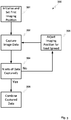
- Figure 3 illustrates a method according to some examples of the invention.
- the method starts by initializing the imaging device, such as the in-line camera 206, to a first imaging position.
- image data for a first spread is then captured by the image capture device.
- a check is then made to determine if the required, N, number of data sets have been captured 304, and if not the method proceeds to step 306 in which the imaging position is adjusted for the next spread.
- the image data for the next spread is then captured 302 at the adjusted imaging position and a further check is made to determine if the desired number of data sets have been captured. This loop continues for subsequent spreads until the desired number of data sets has been captured, and then the method proceeds to step 308 in which the data sets are combined to generate an oversampled image representative of the output of the printing press.
- the CPR error along the substrate can be described as twelve discrete values, however due to a high process velocity only four can be captured by the in-line camera in one spread.
- the graph in Figure 4 shows the ability of a continuous calibration algorithm to reevaluate the data based on only the four data points as compared to if the whole 12 data points are captured over three spreads using the described oversampling technique.
- a third order polynomial fit For the scenario in which only four data points are recorded, it is only possible to apply a third order polynomial fit to the data, however a further advantage of the described techniques is that a larger number of data points allows a higher order polynomial regression to be applied to the data. It is clear from the plots shown in Figure 3 that very different results, and therefore different calibration settings, result from four data points as opposed to twelve data points supplied using the oversampled technique.
- Figure 4 provides a histogram of the difference between the fit and the original data points. As can be seen in Figure 4 , the errors associated with the fitted data are significantly reduced for the oversampled (twelve data points) examples, as opposed to the four data points available without oversampling.
- some examples of the invention are able to provide oversampled image data by combining image data captured from different portions of sequential spreads.
- the multiple sequential spreads can be assumed to be identical and therefore, combining the data captured from different spreads provides a high resolution output without requiring use of a higher speed/resolution camera. Therefore, the use of oversampled image data may increase the accuracy of captured data over prior art cases without limiting throughput of the printing device, or requiring a more expensive high speed image capture system to be used.
Description
- Modern printers and printing presses can include a number of technologies to help ensure accurate reproduction of the printed subject matter. For individual or small numbers of prints accurate calibration of the printing device before printing may ensure accurate reproduction. However, for high numbers of consecutive prints, gradual changes, such as positional errors, in the printing device may accumulate over time leading to a loss of accuracy towards the end of a print run. European patent application
EP2537677 describes a web inspection system for a rotary press, and European patent applicationEP 2422980 describes a colour measurement system for a rotary printing press. - One way of ensuring ongoing accuracy of reproduction during a large print run is to implement continuous calibration of the print device during operation. By monitoring the spreads, or prints, produced by the printing device during the run, errors may be detected and calibration information updated to compensate for any changes and ensure the accuracy of each output print remains within desired tolerances.
- Such continuous calibration may require the output of the printing device to be monitored throughout the print run. Typically, this is achieved using one or more image capture devices, such as an in-line camera or in-line scanner. However, commonly used image capture devices may have limited operating speed, or may have limited resolution when operating at high speeds. This means that the throughput of the printing device may be limited by the operating speed of the image capture device when applying continuous calibration.
- In general, a higher throughput of a printing device, such as a printing press, is desired as this allows an operator to maximize the productivity of the press which may represent a substantial capital investment. Thus, a continuous calibration process that reduces the throughput of the printing device may not be appropriate for some end users. Alternatively, reducing the resolution of the image capture device can lead to the resolution of data points captured by the device being poor, and this in turn limits the ability to accurately detect and correct errors during print runs.
- One possible solution would be to use an image capture device with a higher sampling rate. However, such devices are much more expensive and generally have limited resolution leading to the problems described above. An alternative approach has been to employ more advanced algorithms to attempt to overcome the inherent limitations in the image capture hardware. However, such approaches remain limited by the quality of data captured.
- Aspects of the invention are defined according to the independent claims. Additional advantageous embodiments are disclosed according to the appended dependent claims.
- Examples of the present invention are further described hereinafter by way of example only with reference to the accompanying drawings, in which:
-
Figure 1 illustrates image lines captured from successive spreads according to one example of the invention; -
Figure 2 illustrates a system operable to implement example of the invention; -
Figure 3 illustrates a method according to an example of the invention; -
Figure 4 shows a graph of image data captured using different image capture methodologies; and -
Figure 5 shows a graph illustrating the accuracy of image data captured using the different image capture methodologies. - In order to provide high resolution data of spreads passing through a printing device, without limiting throughput of the printing device, the present invention applies a method of oversampling using an image capturing device. The described method is applicable to a range of image sampling devices, such as an in-line camera, in-line scanner, in-line spectrophotometer, or the like.
- In general, it can be assumed that changes in the behavior of the printing device over time are relatively slow, and therefore a sequence of a small number of consecutive spreads can be assumed to reflect the same behavior. The invention exploits the slow changes in the printing device by combining relatively low resolution data captured from a number of spreads into a single high resolution image or data point.
- The method relies on shifting a position of the image capturing device between spreads, such that a different portion of a spread is captured for each spread in a sequence of spreads, which when combined allow an image of higher density than the capability of the device in the given process velocity to be produced. The disclosed method collects data over more than one spread, and for each spread shifts the camera capture location in a phase with respect to the original location. For example, some examples may use two spreads with a phase of half the distance between two registration marks, three spreads with a phase of third that distance, etc.
-
Figure 1 shows one arrangement in which different captured portions of a number ofspreads higher resolution representation 104 of the output of the printing device. In the example shown inFigure 1 , the capture location of the image capture device relative to the spreads is shifted by a third of the distance between two registration marks 102 between measurement of each spread. Thus, for a first spread 100a image data corresponding toregistration marks 102a is captured by the image capture device, and for second 100b and third 100c subsequent spreads image data corresponding toregistration marks - The image data captured from each spread can then be combined to produce an
oversampled image 104. Thus, the image capture device can operate at relatively low resolution and/or speed while still enabling ahigh resolution image 104 of the spreads to be generated to enable accurate continuous calibration of the printing device. - One example implementation is the specific case of continuous calibration of the Colour Plane Registration (CPR) using an In-Line Camera. Colour plane misregistration is a common problem in printing presses, and in particular sheet fed presses. In the sheet fed process, the printed separations are transferred from a blanket to a substrate one after the other, and hence, different colours may be deposited shifted one from the other in the final print. This results in significant printing artifacts and a reduced perceived quality of the printing press output.
- To continuously calibrate the CPR in a printing device, an In-Line Camera may be used. The CPR error may differ depending on the location on the substrate, and the task of the calibration algorithm is to reevaluate the CPR error for all possible locations on the substrate based on the measurements taken by the In-Line Camera. The CPR error for each location may be evaluated using a polynomial for on the measured data points. The process velocity may typically be more than 2000 mm/s, and therefore the ability of the In-Line Camera to capture a sufficient number of shots along an individual substrate is very limited.
- However, by performing the desired measurements across a number of spreads, the operating speed of the In-Line Camera can be decoupled from the process velocity of the printing press. For example, by performing the required image capture over two spreads, the time available for the In-Line Camera to capture the desired image data is doubled, and for three spreads, tripled, and so on. In common with many changes in the printing press, CPR errors generally change slowly in time, and thus several following spreads can be regarded as reflecting the same CPR error behavior. This means that the image data captured from a number of following spreads can be combined to accurately reflect the CPR errors present at the output of the printing press.
-
Figure 2 illustrates asystem 200 for implementing some examples of the invention. Thesystem 200 comprises aprint controller 202 that controls aprint unit 208 to transfer an image to asubstrate 212. An in-line camera 206 images the printed substrate and provides the captured image data to acalibration controller module 204 that includesoversampling module 214. Thecalibration controller 204 is coupled to theprint controller 202 to supply calibration information for use in controlling theprint unit 208. Thesubstrate 212 is drawn through the system, and past both theprint unit 208 and the in-line camera 206 byrollers 210. - In operation, a first printed
substrate 212 travels past the in-line camera 206 which captures image data for a first portion of the substrate under control of theoversampling module 214. The in-line camera 206 then captures a second portion of a second printed substrate, and so on for further substrates as required. Theoversampling module 214 receives the captured first portion and the captured second portion, etc. and combines the captured portions of the substrates into a single oversampled image. The oversamples image is then used in thecalibration controller 204 as part of a continuous calibration algorithm to identify any changes in the operation of the printing press, such as CPR errors. Thecalibration controller 204 then provides updated calibration information to theprint controller 202 to ensure the operation of the printing device remains within the desired tolerances for the print run. -
Figure 3 illustrates a method according to some examples of the invention. According to themethod 300 ofFigure 3 , the method starts by initializing the imaging device, such as the in-line camera 206, to a first imaging position. Atstep 302, image data for a first spread is then captured by the image capture device. A check is then made to determine if the required, N, number of data sets have been captured 304, and if not the method proceeds to step 306 in which the imaging position is adjusted for the next spread. The image data for the next spread is then captured 302 at the adjusted imaging position and a further check is made to determine if the desired number of data sets have been captured. This loop continues for subsequent spreads until the desired number of data sets has been captured, and then the method proceeds to step 308 in which the data sets are combined to generate an oversampled image representative of the output of the printing press. - In an example, we assume that the CPR error along the substrate can be described as twelve discrete values, however due to a high process velocity only four can be captured by the in-line camera in one spread. The graph in
Figure 4 shows the ability of a continuous calibration algorithm to reevaluate the data based on only the four data points as compared to if the whole 12 data points are captured over three spreads using the described oversampling technique. For the scenario in which only four data points are recorded, it is only possible to apply a third order polynomial fit to the data, however a further advantage of the described techniques is that a larger number of data points allows a higher order polynomial regression to be applied to the data. It is clear from the plots shown inFigure 3 that very different results, and therefore different calibration settings, result from four data points as opposed to twelve data points supplied using the oversampled technique. -
Figure 4 provides a histogram of the difference between the fit and the original data points. As can be seen inFigure 4 , the errors associated with the fitted data are significantly reduced for the oversampled (twelve data points) examples, as opposed to the four data points available without oversampling. - The results of further statistical calculations on the above example result in the information shown in the table below. As can clearly be seen, the size of one standard deviation in the measurement error is significantly reduced, and therefore the accuracy of the captured data is significantly increased through use of the described oversampling technique.
Standard Deviation 95 Percentile 4 data points; 3rd order polynomial 60.7 µm 122.7 µm 12 data points; 3rd order polynomial 30.4 µm 38.8 µm 12 data points; 6th order polynomial 5.9 µm 11.7 µm - The above examples have been described in the context of continuous calibration of colour plane registration using an in-line camera. However, the disclosed technique may be applied to other calibration tasks, for example calibration of print density or uniformity at different wavelengths using an in-line spectrophotometer or to calibrate scaling linearity of a printer using an in-line scanner or camera.
- Thus, some examples of the invention are able to provide oversampled image data by combining image data captured from different portions of sequential spreads. As calibrated aspects of a printer can be assumed to change relatively slowly, the multiple sequential spreads can be assumed to be identical and therefore, combining the data captured from different spreads provides a high resolution output without requiring use of a higher speed/resolution camera. Therefore, the use of oversampled image data may increase the accuracy of captured data over prior art cases without limiting throughput of the printing device, or requiring a more expensive high speed image capture system to be used.
- Throughout the description and claims of this specification, the words "comprise" and "contain" and variations of them mean "including but not limited to", and they are not intended to (and do not) exclude other moieties, additives, components, integers or steps. Throughout the description and claims of this specification, the singular encompasses the plural unless the context otherwise requires. In particular, where the indefinite article is used, the specification is to be understood as contemplating plurality as well as singularity, unless the context requires otherwise.
- The invention is not restricted to the details of any foregoing embodiment or example, but by the appended claims.
Claims (15)
- A method of capturing image data of an output of a printing device during a print run comprising identical images, the method comprising:capturing, with an image capturing device having a first resolution and being positioned in a first imaging position, image data of a first printed image;moving the image capturing device to a second imaging position; capturing, with the image capturing device at a second imaging position, image data of a second printed image ;andcombining the first image with the second image to generate oversampled image data representative of the printed image data and having a higher resolution than the captured image data.
- The method of claim 1, wherein the first and second printed images comprise registration marks, and wherein the captured portions of the printed images are captured based on the registration marks.
- The method of claim 1 or claim 2, further comprising moving the image capturing device to a third imaging position and capturing image data of a third printer image, wherein the third imaging position is different from the first or second imaging positions.
- The method of claim 2, wherein the second imaging position is shifted by half the distance between registration marks relative to the first imaging position.
- The method of claim 3, wherein each printed image comprises registration marks, and wherein each imaging position is shifted by a distance equal to the distance between registration marks on printed images divided by the number of portions of image data to be captured.
- The method of claim any preceding claim, further comprising capturing the portion of the image data using one of an in-line camera, an in-line scanner, or a spectrophotometer.
- The method of any of claims 1 to 6, the method further comprising adjusting at least one calibration parameter of the printing device based on the generated high resolution image data.
- The method of claim 7, wherein the at least one calibration parameter comprises one of colour plane registration, uniformity and scaling linearity.
- A apparatus for capturing image data of an output of a printing device during a print run comprising identical images, the apparatus comprising:an image data capture device having a first imaging resolution;means for moving the image capturing device between a first imaging position and a second imaging position;a controller comprising an image combination module, the image combination module configured to control the image data capture device to:capture a first portion of image data of a first printed image using the image capture device at the first imaging position;capture a second portion of image data of a second printed image using the image capture device at the second imaging position; andcombine the first portion with the second portion to generate oversampled image data representative of the printed image data and having a higher resolution than the captured image data.
- The apparatus of claim 9, wherein the image capture device comprises an in-line camera.
- The apparatus of claim 9, wherein the image capture device comprises one of: an in-line scanner or an in-line spectrophotometer.
- A printing device comprising the apparatus of any of claims 9 to 11.
- The printing device of claim 12, wherein the controller is further configured to adjust at least one calibration parameter of the printing device based on the higher resolution image data.
- The printing device of claim 13, wherein the at least one calibration parameter comprises one of colour plane registration, uniformity and scaling linearity.
- A computer program product comprising computer program code configured when executed to cause the device of claim 9 to perform the method of any of claims 1 to 8.
Applications Claiming Priority (1)
| Application Number | Priority Date | Filing Date | Title |
|---|---|---|---|
| PCT/EP2013/066118 WO2015014399A1 (en) | 2013-07-31 | 2013-07-31 | Capturing image data of printer output |
Publications (2)
| Publication Number | Publication Date |
|---|---|
| EP3028440A1 EP3028440A1 (en) | 2016-06-08 |
| EP3028440B1 true EP3028440B1 (en) | 2020-02-12 |
Family
ID=48906264
Family Applications (1)
| Application Number | Title | Priority Date | Filing Date |
|---|---|---|---|
| EP13742650.8A Active EP3028440B1 (en) | 2013-07-31 | 2013-07-31 | Capturing image data of printer output |
Country Status (3)
| Country | Link |
|---|---|
| US (1) | US9779332B2 (en) |
| EP (1) | EP3028440B1 (en) |
| WO (1) | WO2015014399A1 (en) |
Families Citing this family (1)
| Publication number | Priority date | Publication date | Assignee | Title |
|---|---|---|---|---|
| TWI766154B (en) | 2019-03-27 | 2022-06-01 | 旺矽科技股份有限公司 | Probe head and probe card |
Family Cites Families (14)
| Publication number | Priority date | Publication date | Assignee | Title |
|---|---|---|---|---|
| FI78025C (en) | 1987-08-31 | 1989-06-12 | Valtion Teknillinen | Procedure for quality control of printing |
| US4963899A (en) * | 1989-10-11 | 1990-10-16 | Eastman Kodak Company | Method and apparatus for image frame registration |
| KR100413688B1 (en) * | 2001-09-04 | 2003-12-31 | 삼성전자주식회사 | Apparatus for controling of color registration and image density |
| US7187472B2 (en) | 2002-09-03 | 2007-03-06 | Innolutions, Inc. | Active color control for a printing press |
| US7800779B2 (en) | 2005-12-21 | 2010-09-21 | Xerox Corporation | System and method for image based control using inline sensors |
| US7760397B2 (en) | 2007-03-12 | 2010-07-20 | Xerox Corporation | Calibration sheet and method of calibrating a digital printer |
| JP4760949B2 (en) * | 2009-04-23 | 2011-08-31 | コニカミノルタビジネステクノロジーズ株式会社 | Image forming apparatus and front / back registration confirmation paper output method |
| US20110075162A1 (en) * | 2009-09-29 | 2011-03-31 | Saettel John J | Exposure averaging |
| US8620092B2 (en) * | 2010-03-04 | 2013-12-31 | Hewlett-Packard Development Company, L.P. | Determining similarity of two images |
| US20110228115A1 (en) | 2010-03-16 | 2011-09-22 | Microsoft Corporation | Large Format Digital Camera |
| DE202010008409U1 (en) * | 2010-08-31 | 2011-12-07 | Eltromat Gmbh | Apparatus for colorimetry in a rotary printing machine |
| DE202011050535U1 (en) * | 2011-06-22 | 2012-09-24 | Eltromat Gmbh | Web inspection system for rotary printing machines |
| US9046356B2 (en) | 2011-10-10 | 2015-06-02 | Techkon Usa Llc | Automatic optimal positioning of spectrophotometer while measuring moving media |
| US20130172731A1 (en) * | 2011-12-30 | 2013-07-04 | Philip D. Gole | Image-overlay medical evaluation devices and techniques |
-
2013
- 2013-07-31 US US14/908,387 patent/US9779332B2/en not_active Expired - Fee Related
- 2013-07-31 WO PCT/EP2013/066118 patent/WO2015014399A1/en active Application Filing
- 2013-07-31 EP EP13742650.8A patent/EP3028440B1/en active Active
Non-Patent Citations (1)
| Title |
|---|
| None * |
Also Published As
| Publication number | Publication date |
|---|---|
| US9779332B2 (en) | 2017-10-03 |
| US20160189014A1 (en) | 2016-06-30 |
| EP3028440A1 (en) | 2016-06-08 |
| WO2015014399A1 (en) | 2015-02-05 |
Similar Documents
| Publication | Publication Date | Title |
|---|---|---|
| US10311561B2 (en) | Image inspection method, image inspection device, program, and image recording system | |
| US10589519B2 (en) | Method for detecting printing nozzle errors in an inkjet printing machine | |
| JP4363819B2 (en) | Apparatus and method for adjusting an image of a flexographic printing press | |
| JP4615999B2 (en) | Surface treatment equipment for objects | |
| JP7150530B2 (en) | Automatic image sensor calibration | |
| JP6289939B2 (en) | Method for forming a printed image comprising a plurality of sections on a substrate using two ink jet print heads | |
| US6253678B1 (en) | Method of printing to reduce misregistration | |
| RU2053128C1 (en) | Stencil printing machine | |
| US20090020029A1 (en) | Method and apparatus for automatically regulating the registers between imprints in a multi color rotary printing press | |
| US10776677B2 (en) | Control device and inspection device | |
| JP5636349B2 (en) | Sheet-fed digital printing method | |
| US6694883B2 (en) | Method of correcting local, machine-based inking errors in rotary printing machines | |
| US9555618B2 (en) | Method for the automated definition of color test values | |
| EP3028440B1 (en) | Capturing image data of printer output | |
| US6009808A (en) | Method of multicolor printing involving multiple passes through a printing machine | |
| CN102177022A (en) | Printing table arrangement | |
| JP2007069607A (en) | Printing correction method | |
| EP2839966B1 (en) | Liquid discharging apparatus and liquid discharging method | |
| US9235785B2 (en) | Method for controlling the metering of ink in a printing press, printing substrate, printing plate and printing press having a device for creating halftone image data | |
| JP2017071222A (en) | Efficient paper elongation compensation method | |
| JP2008307830A (en) | Printing apparatus | |
| CN111421955B (en) | Color compensation in offset printing | |
| JP3598558B2 (en) | Method and apparatus for detecting periodic continuous defects in printed matter | |
| EP1237723B1 (en) | Digital offset printing registration | |
| WO2019065579A1 (en) | Printing device, image analysis method, program, and image analysis device |
Legal Events
| Date | Code | Title | Description |
|---|---|---|---|
| PUAI | Public reference made under article 153(3) epc to a published international application that has entered the european phase |
Free format text: ORIGINAL CODE: 0009012 |
|
| 17P | Request for examination filed |
Effective date: 20160127 |
|
| AK | Designated contracting states |
Kind code of ref document: A1 Designated state(s): AL AT BE BG CH CY CZ DE DK EE ES FI FR GB GR HR HU IE IS IT LI LT LU LV MC MK MT NL NO PL PT RO RS SE SI SK SM TR |
|
| AX | Request for extension of the european patent |
Extension state: BA ME |
|
| DAX | Request for extension of the european patent (deleted) | ||
| RAP1 | Party data changed (applicant data changed or rights of an application transferred) |
Owner name: HP INDIGO B.V. |
|
| STAA | Information on the status of an ep patent application or granted ep patent |
Free format text: STATUS: EXAMINATION IS IN PROGRESS |
|
| 17Q | First examination report despatched |
Effective date: 20181221 |
|
| GRAP | Despatch of communication of intention to grant a patent |
Free format text: ORIGINAL CODE: EPIDOSNIGR1 |
|
| STAA | Information on the status of an ep patent application or granted ep patent |
Free format text: STATUS: GRANT OF PATENT IS INTENDED |
|
| INTG | Intention to grant announced |
Effective date: 20190920 |
|
| GRAS | Grant fee paid |
Free format text: ORIGINAL CODE: EPIDOSNIGR3 |
|
| GRAA | (expected) grant |
Free format text: ORIGINAL CODE: 0009210 |
|
| STAA | Information on the status of an ep patent application or granted ep patent |
Free format text: STATUS: THE PATENT HAS BEEN GRANTED |
|
| AK | Designated contracting states |
Kind code of ref document: B1 Designated state(s): AL AT BE BG CH CY CZ DE DK EE ES FI FR GB GR HR HU IE IS IT LI LT LU LV MC MK MT NL NO PL PT RO RS SE SI SK SM TR |
|
| REG | Reference to a national code |
Ref country code: GB Ref legal event code: FG4D |
|
| REG | Reference to a national code |
Ref country code: CH Ref legal event code: EP |
|
| REG | Reference to a national code |
Ref country code: AT Ref legal event code: REF Ref document number: 1233663 Country of ref document: AT Kind code of ref document: T Effective date: 20200215 |
|
| REG | Reference to a national code |
Ref country code: IE Ref legal event code: FG4D |
|
| REG | Reference to a national code |
Ref country code: DE Ref legal event code: R096 Ref document number: 602013065696 Country of ref document: DE |
|
| PG25 | Lapsed in a contracting state [announced via postgrant information from national office to epo] |
Ref country code: FI Free format text: LAPSE BECAUSE OF FAILURE TO SUBMIT A TRANSLATION OF THE DESCRIPTION OR TO PAY THE FEE WITHIN THE PRESCRIBED TIME-LIMIT Effective date: 20200212 Ref country code: NO Free format text: LAPSE BECAUSE OF FAILURE TO SUBMIT A TRANSLATION OF THE DESCRIPTION OR TO PAY THE FEE WITHIN THE PRESCRIBED TIME-LIMIT Effective date: 20200512 Ref country code: RS Free format text: LAPSE BECAUSE OF FAILURE TO SUBMIT A TRANSLATION OF THE DESCRIPTION OR TO PAY THE FEE WITHIN THE PRESCRIBED TIME-LIMIT Effective date: 20200212 |
|
| PGFP | Annual fee paid to national office [announced via postgrant information from national office to epo] |
Ref country code: FR Payment date: 20200623 Year of fee payment: 8 |
|
| REG | Reference to a national code |
Ref country code: LT Ref legal event code: MG4D |
|
| REG | Reference to a national code |
Ref country code: NL Ref legal event code: MP Effective date: 20200212 |
|
| PG25 | Lapsed in a contracting state [announced via postgrant information from national office to epo] |
Ref country code: GR Free format text: LAPSE BECAUSE OF FAILURE TO SUBMIT A TRANSLATION OF THE DESCRIPTION OR TO PAY THE FEE WITHIN THE PRESCRIBED TIME-LIMIT Effective date: 20200513 Ref country code: HR Free format text: LAPSE BECAUSE OF FAILURE TO SUBMIT A TRANSLATION OF THE DESCRIPTION OR TO PAY THE FEE WITHIN THE PRESCRIBED TIME-LIMIT Effective date: 20200212 Ref country code: LV Free format text: LAPSE BECAUSE OF FAILURE TO SUBMIT A TRANSLATION OF THE DESCRIPTION OR TO PAY THE FEE WITHIN THE PRESCRIBED TIME-LIMIT Effective date: 20200212 Ref country code: SE Free format text: LAPSE BECAUSE OF FAILURE TO SUBMIT A TRANSLATION OF THE DESCRIPTION OR TO PAY THE FEE WITHIN THE PRESCRIBED TIME-LIMIT Effective date: 20200212 Ref country code: BG Free format text: LAPSE BECAUSE OF FAILURE TO SUBMIT A TRANSLATION OF THE DESCRIPTION OR TO PAY THE FEE WITHIN THE PRESCRIBED TIME-LIMIT Effective date: 20200512 Ref country code: IS Free format text: LAPSE BECAUSE OF FAILURE TO SUBMIT A TRANSLATION OF THE DESCRIPTION OR TO PAY THE FEE WITHIN THE PRESCRIBED TIME-LIMIT Effective date: 20200612 |
|
| PGFP | Annual fee paid to national office [announced via postgrant information from national office to epo] |
Ref country code: GB Payment date: 20200624 Year of fee payment: 8 |
|
| PG25 | Lapsed in a contracting state [announced via postgrant information from national office to epo] |
Ref country code: NL Free format text: LAPSE BECAUSE OF FAILURE TO SUBMIT A TRANSLATION OF THE DESCRIPTION OR TO PAY THE FEE WITHIN THE PRESCRIBED TIME-LIMIT Effective date: 20200212 |
|
| PG25 | Lapsed in a contracting state [announced via postgrant information from national office to epo] |
Ref country code: RO Free format text: LAPSE BECAUSE OF FAILURE TO SUBMIT A TRANSLATION OF THE DESCRIPTION OR TO PAY THE FEE WITHIN THE PRESCRIBED TIME-LIMIT Effective date: 20200212 Ref country code: CZ Free format text: LAPSE BECAUSE OF FAILURE TO SUBMIT A TRANSLATION OF THE DESCRIPTION OR TO PAY THE FEE WITHIN THE PRESCRIBED TIME-LIMIT Effective date: 20200212 Ref country code: ES Free format text: LAPSE BECAUSE OF FAILURE TO SUBMIT A TRANSLATION OF THE DESCRIPTION OR TO PAY THE FEE WITHIN THE PRESCRIBED TIME-LIMIT Effective date: 20200212 Ref country code: PT Free format text: LAPSE BECAUSE OF FAILURE TO SUBMIT A TRANSLATION OF THE DESCRIPTION OR TO PAY THE FEE WITHIN THE PRESCRIBED TIME-LIMIT Effective date: 20200705 Ref country code: SK Free format text: LAPSE BECAUSE OF FAILURE TO SUBMIT A TRANSLATION OF THE DESCRIPTION OR TO PAY THE FEE WITHIN THE PRESCRIBED TIME-LIMIT Effective date: 20200212 Ref country code: LT Free format text: LAPSE BECAUSE OF FAILURE TO SUBMIT A TRANSLATION OF THE DESCRIPTION OR TO PAY THE FEE WITHIN THE PRESCRIBED TIME-LIMIT Effective date: 20200212 Ref country code: DK Free format text: LAPSE BECAUSE OF FAILURE TO SUBMIT A TRANSLATION OF THE DESCRIPTION OR TO PAY THE FEE WITHIN THE PRESCRIBED TIME-LIMIT Effective date: 20200212 Ref country code: SM Free format text: LAPSE BECAUSE OF FAILURE TO SUBMIT A TRANSLATION OF THE DESCRIPTION OR TO PAY THE FEE WITHIN THE PRESCRIBED TIME-LIMIT Effective date: 20200212 Ref country code: EE Free format text: LAPSE BECAUSE OF FAILURE TO SUBMIT A TRANSLATION OF THE DESCRIPTION OR TO PAY THE FEE WITHIN THE PRESCRIBED TIME-LIMIT Effective date: 20200212 |
|
| PGFP | Annual fee paid to national office [announced via postgrant information from national office to epo] |
Ref country code: DE Payment date: 20200622 Year of fee payment: 8 |
|
| REG | Reference to a national code |
Ref country code: DE Ref legal event code: R097 Ref document number: 602013065696 Country of ref document: DE |
|
| REG | Reference to a national code |
Ref country code: AT Ref legal event code: MK05 Ref document number: 1233663 Country of ref document: AT Kind code of ref document: T Effective date: 20200212 |
|
| PLBE | No opposition filed within time limit |
Free format text: ORIGINAL CODE: 0009261 |
|
| STAA | Information on the status of an ep patent application or granted ep patent |
Free format text: STATUS: NO OPPOSITION FILED WITHIN TIME LIMIT |
|
| 26N | No opposition filed |
Effective date: 20201113 |
|
| PG25 | Lapsed in a contracting state [announced via postgrant information from national office to epo] |
Ref country code: IT Free format text: LAPSE BECAUSE OF FAILURE TO SUBMIT A TRANSLATION OF THE DESCRIPTION OR TO PAY THE FEE WITHIN THE PRESCRIBED TIME-LIMIT Effective date: 20200212 Ref country code: AT Free format text: LAPSE BECAUSE OF FAILURE TO SUBMIT A TRANSLATION OF THE DESCRIPTION OR TO PAY THE FEE WITHIN THE PRESCRIBED TIME-LIMIT Effective date: 20200212 |
|
| PG25 | Lapsed in a contracting state [announced via postgrant information from national office to epo] |
Ref country code: PL Free format text: LAPSE BECAUSE OF FAILURE TO SUBMIT A TRANSLATION OF THE DESCRIPTION OR TO PAY THE FEE WITHIN THE PRESCRIBED TIME-LIMIT Effective date: 20200212 Ref country code: SI Free format text: LAPSE BECAUSE OF FAILURE TO SUBMIT A TRANSLATION OF THE DESCRIPTION OR TO PAY THE FEE WITHIN THE PRESCRIBED TIME-LIMIT Effective date: 20200212 Ref country code: MC Free format text: LAPSE BECAUSE OF FAILURE TO SUBMIT A TRANSLATION OF THE DESCRIPTION OR TO PAY THE FEE WITHIN THE PRESCRIBED TIME-LIMIT Effective date: 20200212 |
|
| REG | Reference to a national code |
Ref country code: CH Ref legal event code: PL |
|
| REG | Reference to a national code |
Ref country code: BE Ref legal event code: MM Effective date: 20200731 |
|
| PG25 | Lapsed in a contracting state [announced via postgrant information from national office to epo] |
Ref country code: LU Free format text: LAPSE BECAUSE OF NON-PAYMENT OF DUE FEES Effective date: 20200731 Ref country code: LI Free format text: LAPSE BECAUSE OF NON-PAYMENT OF DUE FEES Effective date: 20200731 Ref country code: CH Free format text: LAPSE BECAUSE OF NON-PAYMENT OF DUE FEES Effective date: 20200731 |
|
| PG25 | Lapsed in a contracting state [announced via postgrant information from national office to epo] |
Ref country code: BE Free format text: LAPSE BECAUSE OF NON-PAYMENT OF DUE FEES Effective date: 20200731 |
|
| PG25 | Lapsed in a contracting state [announced via postgrant information from national office to epo] |
Ref country code: IE Free format text: LAPSE BECAUSE OF NON-PAYMENT OF DUE FEES Effective date: 20200731 |
|
| REG | Reference to a national code |
Ref country code: DE Ref legal event code: R119 Ref document number: 602013065696 Country of ref document: DE |
|
| GBPC | Gb: european patent ceased through non-payment of renewal fee |
Effective date: 20210731 |
|
| PG25 | Lapsed in a contracting state [announced via postgrant information from national office to epo] |
Ref country code: GB Free format text: LAPSE BECAUSE OF NON-PAYMENT OF DUE FEES Effective date: 20210731 Ref country code: DE Free format text: LAPSE BECAUSE OF NON-PAYMENT OF DUE FEES Effective date: 20220201 |
|
| PG25 | Lapsed in a contracting state [announced via postgrant information from national office to epo] |
Ref country code: TR Free format text: LAPSE BECAUSE OF FAILURE TO SUBMIT A TRANSLATION OF THE DESCRIPTION OR TO PAY THE FEE WITHIN THE PRESCRIBED TIME-LIMIT Effective date: 20200212 Ref country code: MT Free format text: LAPSE BECAUSE OF FAILURE TO SUBMIT A TRANSLATION OF THE DESCRIPTION OR TO PAY THE FEE WITHIN THE PRESCRIBED TIME-LIMIT Effective date: 20200212 Ref country code: FR Free format text: LAPSE BECAUSE OF NON-PAYMENT OF DUE FEES Effective date: 20210731 Ref country code: CY Free format text: LAPSE BECAUSE OF FAILURE TO SUBMIT A TRANSLATION OF THE DESCRIPTION OR TO PAY THE FEE WITHIN THE PRESCRIBED TIME-LIMIT Effective date: 20200212 |
|
| PG25 | Lapsed in a contracting state [announced via postgrant information from national office to epo] |
Ref country code: MK Free format text: LAPSE BECAUSE OF FAILURE TO SUBMIT A TRANSLATION OF THE DESCRIPTION OR TO PAY THE FEE WITHIN THE PRESCRIBED TIME-LIMIT Effective date: 20200212 Ref country code: AL Free format text: LAPSE BECAUSE OF FAILURE TO SUBMIT A TRANSLATION OF THE DESCRIPTION OR TO PAY THE FEE WITHIN THE PRESCRIBED TIME-LIMIT Effective date: 20200212 |