EP3027839B1 - Schwimmendes offshore-schiff und verfahren zum betrieb davon - Google Patents
Schwimmendes offshore-schiff und verfahren zum betrieb davon Download PDFInfo
- Publication number
- EP3027839B1 EP3027839B1 EP14720544.7A EP14720544A EP3027839B1 EP 3027839 B1 EP3027839 B1 EP 3027839B1 EP 14720544 A EP14720544 A EP 14720544A EP 3027839 B1 EP3027839 B1 EP 3027839B1
- Authority
- EP
- European Patent Office
- Prior art keywords
- mode
- emergency
- hoisting system
- floating vessel
- valve
- Prior art date
- Legal status (The legal status is an assumption and is not a legal conclusion. Google has not performed a legal analysis and makes no representation as to the accuracy of the status listed.)
- Not-in-force
Links
- 238000000034 method Methods 0.000 title description 10
- 239000012530 fluid Substances 0.000 claims description 17
- 230000000903 blocking effect Effects 0.000 claims description 12
- 230000007246 mechanism Effects 0.000 claims description 10
- 230000008859 change Effects 0.000 claims description 7
- 238000004891 communication Methods 0.000 claims description 7
- 230000004913 activation Effects 0.000 claims description 6
- 238000005553 drilling Methods 0.000 description 25
- 229910000831 Steel Inorganic materials 0.000 description 6
- 239000010959 steel Substances 0.000 description 6
- 230000008901 benefit Effects 0.000 description 4
- 238000012360 testing method Methods 0.000 description 4
- 230000000694 effects Effects 0.000 description 2
- 230000007257 malfunction Effects 0.000 description 2
- 239000003305 oil spill Substances 0.000 description 2
- 230000008569 process Effects 0.000 description 2
- 230000007704 transition Effects 0.000 description 2
- 230000001133 acceleration Effects 0.000 description 1
- 238000013459 approach Methods 0.000 description 1
- 230000015572 biosynthetic process Effects 0.000 description 1
- 239000012809 cooling fluid Substances 0.000 description 1
- 238000013016 damping Methods 0.000 description 1
- 230000001419 dependent effect Effects 0.000 description 1
- 230000005484 gravity Effects 0.000 description 1
- 230000002401 inhibitory effect Effects 0.000 description 1
- 238000012423 maintenance Methods 0.000 description 1
- 238000012986 modification Methods 0.000 description 1
- 230000004048 modification Effects 0.000 description 1
- 230000004044 response Effects 0.000 description 1
- 239000013535 sea water Substances 0.000 description 1
- 238000013519 translation Methods 0.000 description 1
Images


Classifications
-
- B—PERFORMING OPERATIONS; TRANSPORTING
- B66—HOISTING; LIFTING; HAULING
- B66C—CRANES; LOAD-ENGAGING ELEMENTS OR DEVICES FOR CRANES, CAPSTANS, WINCHES, OR TACKLES
- B66C13/00—Other constructional features or details
- B66C13/04—Auxiliary devices for controlling movements of suspended loads, or preventing cable slack
- B66C13/06—Auxiliary devices for controlling movements of suspended loads, or preventing cable slack for minimising or preventing longitudinal or transverse swinging of loads
-
- B—PERFORMING OPERATIONS; TRANSPORTING
- B63—SHIPS OR OTHER WATERBORNE VESSELS; RELATED EQUIPMENT
- B63B—SHIPS OR OTHER WATERBORNE VESSELS; EQUIPMENT FOR SHIPPING
- B63B35/00—Vessels or similar floating structures specially adapted for specific purposes and not otherwise provided for
- B63B35/44—Floating buildings, stores, drilling platforms, or workshops, e.g. carrying water-oil separating devices
- B63B35/4413—Floating drilling platforms, e.g. carrying water-oil separating devices
-
- B—PERFORMING OPERATIONS; TRANSPORTING
- B66—HOISTING; LIFTING; HAULING
- B66C—CRANES; LOAD-ENGAGING ELEMENTS OR DEVICES FOR CRANES, CAPSTANS, WINCHES, OR TACKLES
- B66C13/00—Other constructional features or details
- B66C13/02—Devices for facilitating retrieval of floating objects, e.g. for recovering crafts from water
-
- B—PERFORMING OPERATIONS; TRANSPORTING
- B66—HOISTING; LIFTING; HAULING
- B66D—CAPSTANS; WINCHES; TACKLES, e.g. PULLEY BLOCKS; HOISTS
- B66D3/00—Portable or mobile lifting or hauling appliances
- B66D3/04—Pulley blocks or like devices in which force is applied to a rope, cable, or chain which passes over one or more pulleys, e.g. to obtain mechanical advantage
- B66D3/043—Block and tackle system with variable number of cable parts
-
- E—FIXED CONSTRUCTIONS
- E21—EARTH OR ROCK DRILLING; MINING
- E21B—EARTH OR ROCK DRILLING; OBTAINING OIL, GAS, WATER, SOLUBLE OR MELTABLE MATERIALS OR A SLURRY OF MINERALS FROM WELLS
- E21B19/00—Handling rods, casings, tubes or the like outside the borehole, e.g. in the derrick; Apparatus for feeding the rods or cables
- E21B19/08—Apparatus for feeding the rods or cables; Apparatus for increasing or decreasing the pressure on the drilling tool; Apparatus for counterbalancing the weight of the rods
- E21B19/09—Apparatus for feeding the rods or cables; Apparatus for increasing or decreasing the pressure on the drilling tool; Apparatus for counterbalancing the weight of the rods specially adapted for drilling underwater formations from a floating support using heave compensators supporting the drill string
Definitions
- the present invention relates to an offshore floating vessel.
- a floating vessel used for drilling operations e.g. a semi-submersible drilling rig or a drill ship
- sea waves impart an up and down motion to the vessel (known as 'heave'), the period of which can range from a few seconds to 25 s or so, and can be of a few centimeters to 15 m or more in amplitude.
- This up and down motion is imparted to a load attached to the vessel.
- the motion of the load is highly undesirable and even dangerous to equipment and personnel. For example when attempting to drill a wellbore in the sea floor, the motion can cause a corresponding motion of the drill string.
- the up and down movement of the drill bit is highly undesirable and severely restricts the operating window of the rig. For example, it is estimated that in the North Sea as much as 20% of rig operating time is lost 'waiting on weather' i.e. waiting for better weather when the sea is calmer.
- Active heave compensation is concerned with reducing the effect of this up and down motion on a load attached to the vessel via a connecting device (e.g. a travelling block, top drive, or the like).
- a connecting device e.g. a travelling block, top drive, or the like.
- So-called 'passive' active heave compensation methods are known which rely on the load being fixed at some other point (e.g. to the sea floor). Sea swell causes the vessel to move relative to the load and a passive compensator uses compressed air to provide a low frequency damping effect between the load and the vessel.
- An active heave compensation method involves measuring the movement of the vessel using a measuring device (for example a Motion Reference Unit or MRU) and using a signal representing the motion of the vessel to control a drive for moving the connecting device relative to the vessel.
- a measuring device for example a Motion Reference Unit or MRU
- MRU Motion Reference Unit
- a signal representing the motion of the vessel to control a drive for moving the connecting device relative to the vessel.
- the connecting device is moved in a manner equal but opposite to the motion of the vessel the heave can be substantially cancelled.
- a major advantage of active heave compensation is that it does not rely on movement of the load itself relative to the vessel before compensation can be applied.
- the first mode will also be referred to as hoisting mode
- the second mode will also be referred to active heave compensation mode.
- Such emergency brakes are provided so as to avoid losing control over the load and/or vessel in situations of failure.
- the emergency brakes prevent heavy loads, such as blowout preventers (BOPs), from descending to the sea floor in an uncontrolled fashion.
- BOPs blowout preventers
- Such emergency brakes may e.g. be disc brakes or another suitable form of brakes.
- an offshore floating vessel comprising a hoisting system adapted for suspending a load attached to a connecting device of the floating vessel and for lowering or raising a load connected to the connecting device from the floating vessel towards or from the sea floor;
- the hoisting system comprising a drive for moving the connecting device and one or more emergency brakes configured to inhibit motion of the connecting device, in particular to inhibit upward and/or downward motion of the connecting device so as to secure the load;
- the hoisting system is configured to be operated at least in a hoisting mode and in an active heave compensation mode; wherein the hoisting system is configured to perform an active heave compensation when operated in the active heave compensation mode and to operate without active heave compensation when operated in the hoisting mode;
- the one or more emergency brakes are operable in a normally-energized mode including a de-energized state where the emergency brakes engage so as to inhibit motion of the connecting device; wherein the hoisting system is further operable in a
- a hoisting system may selectively be operated in a mode without active heave compensation and in a second mode with active heave compensation, where emergency brakes are operable in both modes.
- the hoisting system is selectively operable in a fixed-to-bottom mode where the active heave compensation is operational but where the emergency brakes are prevented from engaging.
- the fixed-to-bottom mode may be regarded as a sub-mode of the active heave operation mode.
- the floating vessel may be a vessel for drilling operations in the seabed, e.g. a semi-submersible or a drill ship.
- the hoisting systems may be any suitable hoisting system such as based on a drawworks or similar drive system.
- the drive controlling motion of the connecting device may comprise a drawworks such as an AC drawworks or a DC drawworks.
- a drawworks is a powerful (e.g. 6 MW) winch that is connected to the connecting device by a cable that passes through a block and tackle arrangement. Reeling in and out of the cable causes the connecting device to be raised and lowered relative to the vessel.
- the hoisting system may be supported by a support structure, such as a derrick, extending upward relative to a deck of the floating vessel.
- a floating vessel may comprise a support structure upwardly extending relative to a deck of the floating vessel and supporting a hoisting system for hoisting and lowering tubulars (such as drill strings, casings and/or risers) through a well centre towards the sea floor so that drilling into the seabed can be performed.
- tubulars such as drill strings, casings and/or risers
- Lowering or raising a load towards/from the seafloor may include lowering the load partly towards the sea floor or all the way to the sea floor.
- at least a part e.g. one end of a pipe or string
- the term inhibiting motion of the connecting device is intended to refer to the upward/downward motion (i.e. along a direction towards/away from the sea floor) of the connecting device and to a motion relative to the floating vessel. It will be appreciated that, with the brakes engaged, the connecting device will follow the heave of the vessel.
- the term preventing the emergency brakes at least temporarily from engaging is intended to comprise embodiments where the emergency brakes are not permanently prevented from engaging but only for some limited period of time, e.g. due to the nature of the mechanism used for preventing engaging of the brake.
- Such time is preferably selected sufficiently long for the crew of the floating vessel to bring the hoisting system in a safe situation, e.g. by disconnecting the string, pipe or other equipment that is fixed to the sea floor in a controlled manner, or by otherwise preventing a breaking of the pipe, string or the like to have serious undesired consequences.
- the actual amount of time the system is configured to prevent or delay the emergency brakes from engaging may depend on the type of equipment and/or the type of operations.
- the delay time may e.g.
- ⁇ 10 s, e.g. at least 30 s, e.g. at least 1 min., at least 5 min., e.g. at least 10 min., e.g. at least 30 min., e.g. at least 1 h, e.g. at least several hours, e.g. at least one or even several days.
- the hoisting system when operated in the active heave compensation mode, is further adapted to stop active heave compensation responsive to one or more predetermined error conditions.
- error conditions may be error conditions of the motor operating the drawworks such as low oil pressure, high temperature of the cooling fluid, etc.
- a control system of the hoisting system may initiate corresponding alarms, such as audible or visible alarms. If the operator of the hoisting system ignores these alarms, the control system may automatically stop the hoisting system and engage the emergency brakes.
- the hoisting system when operated in the fixed-to-bottom mode, is adapted to maintain active heave compensation despite said one or more predetermined error conditions.
- the active heave compensation is continued even in certain error situations that would normally cause the active heave compensation to be discontinued so as to avoid damage of the drawworks motors or the like.
- the emergency brakes are normally-energized, i.e. they remain in an engaged state until they are energized, and thus inhibit motion of the connecting device unless they are energized.
- such brakes have a fail-safe state in which they are engaged: Power is required to maintain them in a disengaged state and, in case of power failure or another malfunction, they engage to stop motion of the load without the need for power.
- the emergency brakes may be spring-loaded disc brakes or other hydraulic brakes that are kept in an engaged position by a spring and require fluid pressure to open.
- the hoisting system comprises a plurality of hydraulic emergency brakes and a hydraulic system configured to maintain the emergency brakes in a disengaged state by applying a hydraulic pressure to each of said emergency brakes by means of a pressurized fluid; wherein the hydraulic system comprises a plurality of accumulator reservoirs for accommodating hydraulic fluid, each accumulator reservoir being in fluid communication with one or more of the emergency brakes via a respective conduit so as to provide hydraulic pressure to the corresponding emergency brake during a failure of the hydraulic system; wherein each conduit comprises a valve for selectively opening and closing the conduit; and wherein the hoisting system is operable to set each of said valves in an open position only when the hoisting system is operated in the fixed-to-bottom mode.
- the hoisting system may comprise a plurality of emergency brakes and the system may be configured to provide efficient emergency braking even if one of the emergency brakes malfunctions.
- the accumulator reservoirs allow maintaining of the operational pressure on the emergency brakes, at least for a certain period of time, even in case of failure of the hydraulic system, thus preventing the emergency brakes from engaging during fixed-to-bottom operations.
- failure of one of the reservoirs only causes one of the emergency brakes to engage.
- the hoisting system may further be dimensioned such that the drive may still be operable to continue active heavy compensation if only one of the emergency brakes is applied.
- the hoisting system may comprise alternative or additional mechanisms for preventing the emergency brakes from engaging when the hoisting system is operated in the fixed-to-bottom mode.
- the hoisting system comprises a respective mechanical blocking mechanism comprising a blocking member, e.g. a wedge, associated with each of the emergency brakes, the mechanical blocking member being movable between a first and a second position, wherein the mechanical blocking member, when located in its first position, prevents the emergency brake from engaging and, when located in its second position, allows the emergency brake to engage.
- each emergency brake is selectively operable in an enabled state and a disabled state, and wherein the emergency brake is operable to change between said states only responsive to a respective activation signal.
- the emergency brake remains in that state unless actively actuated, e.g. by an electrical signal, hydraulic pressure, and/or another positive actuator signal. Consequently, the emergency brakes are prevented from changing state in an uncontrolled manner.
- the emergency brakes further comprise a sensor operable to indicate the present state of the emergency brake
- the hoisting system may condition operation of the hoisting system in the hoisting mode, the active heave compensation mode or the fixed-to-bottom mode on sensor signals received from said sensors.
- the hoisting system may be operable to allow operation of the hoisting system in fixed-to-bottom mode only if the sensor signal indicates that the emergency brakes are in the disabled state.
- the hoisting system may be operable to allow operation of the hoisting system in hoisting mode or active heave compensation mode only if the sensor signal indicates that the emergency brakes are in the enabled state.
- first valve and the second valve connected to each emergency brake are operationally coupled to each other so as to prevent operation of one of the first and second valves without operating the other valve.
- first and second valve may be embodied in a single valve block and actuated by the same actuator. Hence, reliable switching between the operational states is ensured.
- emergency brakes may also be used for other operational purposes, e.g. as parking brakes and/or for controlling the speed of lowering a load.
- primary braking during normal operation may be performed by the motor or motors driving the drawworks.
- valve(s) controlling operation of a hydraulic brakes in a disabled or enabled state may be configured to remain, regardless of their current operational position, in said current operational position unless energized.
- a mechanical blocking member may be configured to remain, regardless its current operational position (blocking/non-blocking), in said current operational position unless energized.
- the valves or mechanical blocking member do not comprise any automatic spring return when de-energized.
- the hoisting system is operable to change between said fixed-to-bottom mode and at least one other operation mode responsive to a manual remote operating mechanism for back-up/emergency operation.
- the emergency brake may be operable to change between its enabled and disabled states responsive to a manual remote operating mechanism for back-up/emergency operation. Consequently a manual intervention/changeover is allowed for.
- the term "manual remote operation" is intended to refer to an operator operation interface that allows an operator to enable/disable the emergency brakes without having to enter the drawworks machine in order to change between the states of the brakes.
- the remote operating mechanism is sealed and padlocked or otherwise protected against unauthorized operation.
- the present invention relates to different aspects including the floating vessel described above and in the following, corresponding apparatus, systems, methods, and/or product means, each yielding one or more of the benefits and advantages described in connection with the first mentioned aspect, and each having one or more embodiments corresponding to the embodiments described in connection with the first mentioned aspect and/or disclosed in the appended claims.
- a method for operating a floating vessel comprising a hoisting system adapted for suspending a load attached to a connecting device of the floating vessel and for raising or lowering a load connected to the connecting device from the floating vessel to or from the sea floor; the hoisting system comprising a drive for moving the connecting device and one or more emergency brakes configured to inhibit motion of the connecting device relative to the vessel, in particular to inhibit upward and/or downward motion of the connecting device so as to secure the load; wherein the method comprises
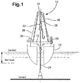
- a floating drilling rig generally identified by reference numeral10 comprises a drill ship having a rig floor 12 supported on a hull14. In this way the drilling rig floats at the surface with the rig floor supported some 15-30 m thereabove.
- the floating drilling rig 10 may be any type of vessel or floating rig, including a semi -submersible.
- the drill floor of a semi-submersible is supported on columns that in turn are supported by pontoons.
- the pontoons are flooded with sea water such that the pontoons are submerged to a predetermined depth below the surface of the sea.
- the rig floor 12 supports a derrick 16 that comprises a crown block 18 (fixed relative to the derrick), and a travelling block 20 (moveable up and down the height of the derrick).
- a hook 22 is suspended from the travelling block 20 for picking up loads such as a drill string 24 via a top drive 25.
- the travelling block 20 and hook 22 perform the function of a connecting device for connecting/suspending a load 24 to/from the drill ship 10. It will be appreciated, however, that other forms of connecting devices, such as a yoke, etc. may be used.
- Each of the crown block 18 and travelling block 20 comprise a number of sheaves (not shown) through which is threaded a steel rope 26 (sometimes known in the art as a drill line) of 25-50 mm diameter to provide a block and tackle type function.
- a steel rope 26 sometimes known in the art as a drill line
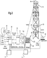
- the drawworks 30 may have dimensions of about 9.22 m width by 3.91 m depth by 4.65 m high, weighs about 84,285 kg (84.3 metric tons), and can provide about 6 MW of power.
- electrical motors 31 in the drawworks 30 turn the drum 29 so as to reel the steel rope 26 in or out. Assuming that the drilling rig 10 is not in motion itself, reeling the steel rope 26 out results in lowering of the travelling block (and anything attached thereto) toward the rig floor 12, whereas reeling the steel rope 26 in results in raising of the travelling block 20 away from the rig floor 12. In this way the drawworks 30 can be used to move objects to and from the sea floor and even into and out of the wellbore, and to perform other functions.
- the electrical motors 31 may be of any type including AC motors, DC motors or permanent magnet motors for example.
- the drawworks 30 comprises an electric drive 32 controlling a number (e.g. four or six) electrical motors 31 for turning the drum 29 via a gear and pinion arrangement 34. All of the electrical motors 31 are permanently engaged with the drum 29, although the number that are in operation at any one time is controlled by the electric drive 32 according to speed and braking requirements.
- Hydraulic disc brakes 36 are operationally coupled to the drum 29 and are operable as emergency brakes. In addition or alternative to the emergency brakes, disc brakes may be provided that provide a "parking" function and/or allow load lowering in the event of a power cut. Some or all of the disc brakes may be operable both as emergency brakes and as parking or other operational brakes.
- the brakes may be operable to press brake pads against a brake disc of the drum 29 by means of a set of calipers.
- the disc brakes may be spring loaded, i.e. they may press the brake pads against the drum by spring force unless the brake is energized, e.g. by means of a hydraulic cylinder causing the brake pads to be pushed away from the drum against the force exerted by the spring.
- the emergency brakes are operationally coupled to a hydraulic system 50 providing hydraulic pressure to the emergency brakes. It will be appreciated, however, that other types of emergency brakes may be used.
- a drawworks controller 38 e.g. comprising a programmable logic controller (PLC) provides speed commands, e.g. via a speed controller to the electric drive 32 based inter alia on motor speed and torque data fed back to the controller 38 from a pulse encoder or other suitable sensor on each electrical motor 31, and on inputs from a driller control apparatus 40.
- the driller control apparatus may comprise a joystick in a driller's cabin on the drilling rig 10; the driller's cabin comprises equipment for computer control of operations on the drilling rig 10. Movement of the joystick by the driller provides an output signal that causes the travelling block 22, via the drawworks 30, to raise or lower the load on the hook 22 at a speed (also controllable via the joystick).
- the drawworks controller 38 also receives inputs from three Motion Reference Units (MRU) 45.
- MRU Motion Reference Units
- the output from each MRU is input to the drawworks controller 38 that processes the signals to provide one output representing the heave acceleration, velocity and position of the drilling rig 10 as a result of ocean swell or heave.
- the drilling rig 10 will oscillate in response to sea swell or waves with a complex motion comprising three translation modes (known as surge, sway and heave) and three angular modes (known as roll, pitch and yaw).
- the drawworks controller 38 uses the inputs from the MRUs to provide active heave compensation when the rig moves with sea swell, e.g. as described in US patent no. US 8,265,811 the entire disclosure is incorporated herein by reference.
- the drilling rig 10 may be operated in different modes of operation, including a hoisting mode 301, an active heave compensation mode 302, and a fixed-to-bottom mode 303.
- the hoisting mode may e.g. be employed when building tubulars or when running a drill string or other tubular equipment or even other subsea equipment towards the sea floor or when raising such equipment from the sea floor.
- Other such operations include operations where no load is suspended from the floating vessel such that (any part of) the load is in the proximity or at the sea floor, in particular no closer to the sea floor than the maximum heave.
- this mode may be preferred when a load is suspended above the sea surface or only slightly below the sea surface.
- active heave compensation is normally not necessary (at least as long the equipment is sufficiently high above the sea floor) and in some embodiments even undesired, as it would typically require unnecessary energy and slow down the hoisting operation. Consequently, in the hoisting mode 301, active heave compensation is disabled or at least not activated. In active heave compensation mode 302, active heave compensation is activated, thus causing the motors 31 to operate the drum 29 responsive to signals from the MRUs or similar sensors in a generally oscillating fashion so as to actively compensate for detected motion of the drilling rig. This mode of operation may e.g.
- the emergency brakes 36 are operational so as to prevent an uncontrolled lowering of loads in cases of e.g.
- the transition 304 between the hoisting mode 301 and the active heave compensation mode 302 is performed responsive to an operator command via the driller control apparatus 40 which in turn activates or deactivates the active heave compensation function of the drawworks controller 38.
- the active heave compensation mode may have one or more sub-modes e.g. each performing a different active heave compensation processes, such as a "BOP and subsea tools landing mode", a "constant WOB mode", and/or the like.
- the drilling rig may have additional main modes of operation.
- the drilling rig may further be operated in a fixed-to-bottom mode 303.
- This mode may e.g. be employed during well testing when a pipe attached to the drilling rig is connected to a well bore and oil is transported to the drill rig.
- a string e.g. a string of tubulars, such as pipes, risers and/or the like, is fixedly connected to the well bore or to heavy subsea equipment such as a BOP on the sea floor.
- active heave compensation is active in this mode of operation.
- the fixed-to-bottom mode 303 may be regarded as a sub-mode of the active heave compensation mode 302.
- emergency brakes are desired during normal active heave compensation modes
- activation of emergency brakes during a fixed-to-bottom operation may have serious consequences including breaking of a string of tubulars resulting in oil spill. Consequently, when operated in fixed-to-bottom mode, the emergency brakes are disabled such that they are prevented from engaging even in a situation of power failure, failure of the hydraulic system or the like.
- the transition 305 between the fixed-to-bottom mode and other modes is performed responsive to an operator command via the driller control apparatus 40.
- the rig can switch directly from the FTB mode 303 and another mode different from AHC 302, e.g. HM 301.
- the drawworks controller when entering the fixed-to-bottom mode, the drawworks controller disables the emergency brakes and when leaving the fixed-to-bottom mode, the drawworks controller re-enables the emergency brakes. Enabling and disabling of the emergency brakes both require a positive activation signal, i.e. the emergency brakes remain in their current state (regardless whether that is the enabled or disabled state) unless they receive a positive signal causing a change of state.
- Each emergency brake further comprises one or more sensors determining whether the brake is in its enabled or disabled state.
- the sensor signals from each emergency brake are fed to the drawworks controller and the driller control apparatus.
- the drawworks controller is configured to perform operation in the selected mode of operation only when the sensor signals indicate that the emergency brakes are in the corresponding state required by the corresponding mode of operation.
- FIG. 4 schematically shows a part of the hydraulic control of an emergency brake 36, e.g. of one of the emergency brakes of the drilling rig of fig. 1 .
- the emergency brake 36 is a hydraulic disc brake comprising a cylinder 442 in which a spring 438 actuates a caliper 437 so as to cause the caliper 437 to push brake pads against the drum 29 of the drawworks so as to inhibit the drum from rotating and, consequently, to inhibit any load attached to the connecting device of the drilling rig from moving up or down.
- the cylinder 442 is in fluid communication via conduit 441 to a hydraulic system 50 which is configured to provide hydraulic pressure to the brake 36 so as to compress spring 438 such that the caliper 437 is in a disengaged position where the brake pads are not in contact with the drum.
- the emergency brake is further in fluid communication via conduit 443 and block and bleed block 452 with an accumulator reservoir 451.
- a first valve 440 is positioned in conduit 443 between emergency brake 36 and reservoir 451.
- a second valve 439 is positioned in conduit 441 between the emergency brake 36 and the hydraulic system 50.
- the reservoir 451 is further in fluid communication with the hydraulic system 50 via conduit 444, thus allowing the hydraulic system to pressurize the reservoir 451.
- a third valve 445 is positioned in the conduit 444 allowing isolating the reservoir 451 and the emergency brake 36 from the hydraulic system 50.
- a shut-off valves 453 may be provided for maintenance purposes.
- the first valve 440 may be switched between an open position and a closed position.
- the second valve 439 may be switched between an open position and a non-return position. In the non-return position, the second valve allows fluid flow from the hydraulic system towards the emergency brake but is closed for return flow, i.e. it prevents hydraulic fluid to return from the cylinder 440 of the emergency brake.
- the third valve 445 may be switched between a closed position and a non-return position. In the non-return position, the third valve allows fluid flow from the hydraulic system towards the reservoir 451 but it is closed for return flow, i.e. it prevents hydraulic fluid to return from the reservoir towards the hydraulic system.
- the first valve When the drilling rig is operated in hoist mode or in active heave compensation mode, the first valve is in its closed position, the second valve is in its open position and the third valve is in its non-return position. Hence, in this state, the emergency brake 36 is isolated from the reservoir. In fact, the reservoir 451 is isolated from the remainder of the system. Consequently, when the hydraulic system reduces the pressure at the emergency brake, the brake is activated by the spring 438. Even if the hydraulic system fails resulting in an unintentional pressure loss, the emergency brake is activated.
- the first valve When the drilling rig is operated in the fixed-to-bottom mode, the first valve is in its open position, the second valve is in its non-return position and the third valve is in its non-return position.
- the emergency brake remains pressurized by the pressure that is still present in the reservoir 451. Consequently, even in situations of malfunctioning of the hydraulic system 50, the emergency brake is prevented from engaging, at least for a certain period of time as long as the reservoir 451 is capable of maintaining a sufficiently high pressure.
- the first, second and third valves are configured such that they always remain, regardless of their current position, in their current position unless positively actuated, i.e. they do not automatically return to another position unless actuated.
- at least the first and second valves and optionally all three valves are interlocked, i.e. configured to only be switchable together.
- the interlocked valves may be provided in a single valve housing and actuated by the same actuator.
- the actual position of the valves is further detected by a position sensor (not shown) and communicated to the drawworks controller.
- hydraulic system 50 may provide hydraulic pressure to multiple emergency brakes, e.g. to all emergency brakes of the drum 29. Nevertheless, each emergency brake 36 has associated with it a separate reservoir 451 and first and second valves 440 and 439, so as to avoid a failure of a single reservoir or valve to inadvertently activate all brakes at the same time.
- FIG. 5 schematically illustrates an alternative mechanism for selectively enabling/disabling an emergency brake.
- an emergency brake 36 is shown which is similar to the emergency brake described in connection with fig. 4 .
- the emergency brake is controlled by a conventional brake control system 50, e.g. a hydraulic system.
- Each emergency brake is associated with a movable blocking member, e.g. a wedge 561, that may be moved between a disengaged position (as shown in fig. 5 ) and an engaged position (as illustrated by arrow 564) where it blocks the caliper 437 from engaging the brake pads.
- Actuation of the wedge 561 is performed by a hydraulic cylinder 562 which is connected to a hydraulic system via valve 563.
- Valve 563 may be switched between two positions. In one position the pressure from the hydraulic system moves the wedge into its engaged position. In the other position the pressure from the hydraulic system moves the wedge into its disengaged position.
- the valve is configured such that it always remains in its current position unless positively actuated, i.e. it does not automatically return to another position unless actuated.
- the actual position of the wedge and/or the valve is further detected by a position sensor (not shown) and communicated to the drawworks controller.
Landscapes
- Engineering & Computer Science (AREA)
- Mechanical Engineering (AREA)
- Geology (AREA)
- Life Sciences & Earth Sciences (AREA)
- Mining & Mineral Resources (AREA)
- General Life Sciences & Earth Sciences (AREA)
- Fluid Mechanics (AREA)
- Environmental & Geological Engineering (AREA)
- Physics & Mathematics (AREA)
- Geochemistry & Mineralogy (AREA)
- Architecture (AREA)
- Civil Engineering (AREA)
- Structural Engineering (AREA)
- Chemical & Material Sciences (AREA)
- Combustion & Propulsion (AREA)
- Ocean & Marine Engineering (AREA)
- Earth Drilling (AREA)
- Control And Safety Of Cranes (AREA)
Claims (11)
- Schwimmendes Offshore-Fahrzeug (10), umfassend ein Hebesystem zum Aufhängen einer an einer Verbindungsvorrichtung des schwimmenden Schiffs (10) befestigten Last und zum Absenken bzw. Anheben einer mit der Verbindungsvorrichtung verbundenen Last (24) von dem schwimmenden Schiff (10) zu oder von dem Meeresboden; wobei das Hebesystem einen Antrieb (32) zum Bewegen der Verbindungsvorrichtung und eine oder mehrere Notbremse(n) (36), die konfiguriert ist/sind, um eine Bewegung der Verbindungsvorrichtung relativ zum schwimmenden Schiff (10) zu hemmen, umfasst;
wobei das Hebesystem konfiguriert ist, um zumindest in einem Hebemodus (301) und in einem aktiven Seegangskompensationsmodus (302) betrieben zu werden; wobei das Hebesystem konfiguriert ist, um eine aktive Seegangskompensation durchzuführen, wenn es im aktiven Seegangskompensationsmodus (302) betrieben wird, und ohne aktive Seegangskompensation zu arbeiten, wenn es im Hebemodus (301) betrieben wird;
wobei die eine oder die mehreren Notbremse(n) (36) in einem selbswirkendem Modus einschließlich eines nicht angeregten Zustands betreibbar ist/sind, bei dem die Notbremsen (36) betätigt werden, um eine Bewegung der Verbindungsvorrichtung relativ zum schwimmenden Schiff (10) zu hemmen;
dadurch gekennzeichnet, dass das Hebesystem ferner in einem Bodenverankerungsmodus (303) betreibbar ist; wobei das Hebesystem konfiguriert ist, um eine aktive Seegangskompensation auszuführen, wenn es im Bodenverankerungsmodus (303) betrieben wird; und wobei das Hebesystem ausgelegt ist, um zumindest zeitweise zu verhindern, dass die Notbremsen (36) betätigt werden. - Schwimmendes Offshore-Schiff (10) nach Anspruch 1; wobei das Hebesystem, wenn es in dem aktiven Seegangskompensationsmodus (302) betrieben wird, ferner ausgelegt ist, die aktive Seegangskompensation in Reaktion auf eine oder mehrere vorbestimmte Fehlerbedingung(en) zu stoppen; und wobei das Hebesystem, wenn es im Bodenverankerungsmodus (303) betrieben wird, ausgelegt ist, die aktive Seegangskompensation trotz der einen oder mehreren vorgegebenen Fehlerbedingung(en) beizubehalten.
- Schwimmendes Offshore-Schiff (10) nach einem der vorhergehenden Ansprüche; umfassend eine Vielzahl von Notbremsen (36).
- Schwimmendes Offshore-Schiff (10) nach Anspruch 3, wobei die Notbremsen (36) hydraulische Bremsen sind; wobei das Hebesystem ein Hydrauliksystem (50) umfasst, das konfiguriert ist, um die Notbremsen (36) in einem betätigten Zustand zu halten, indem ein Hydraulikdruck mittels eines unter Druck stehenden Fluids auf jede der Notbremsen (36) aufgebracht wird; wobei das Hydrauliksystem (50) eine Vielzahl von Speicherbehältern (451) zum Aufnehmen von Hydraulikflüssigkeit umfasst, wobei jeder Speicherbehälter (451) über eine entsprechende Leitung (443) in Fluidverbindung mit einer der Notbremsen (36) steht, um bei einem Ausfall des Hydrauliksystems (50) Hydraulikdruck zu der entsprechenden Notbremse (36) bereitzustellen; wobei jede Leitung (443) ein Ventil (440) zum selektiven Öffnen und Schließen der Leitung (443) umfasst; und wobei das Hebesystem betreibbar ist, um jedes der Ventile (440) nur dann in einer offenen Position einzustellen, wenn das Hebesystem in dem Bodenverankerungsmodus (303) betrieben wird.
- Schwimmendes Offshore-Schiff (10) nach Anspruch 4, wobei jede Notbremse (36) über ein erstes Ventil (440) in Fluidverbindung mit einem separaten Speicherbehälter (451) und über ein zweites Ventil (439) in Fluidverbindung mit einem Hydrauliksystem (50), das einen Betriebsdruck für die Notbremse (36) bereitstellt, steht; wobei das erste Ventil (440) eine offene Position und eine geschlossene Position aufweist und wobei das zweite Ventil (439) eine offene Position und eine Rückschlagposition aufweist, die eine Fluidströmung nur von dem Hydrauliksystem (50) zu der Notbremse (36) erlaubt; wobei das Hebesystem betreibbar ist, um das erste Ventil (440) in der geöffneten Position und das zweite Ventil (439) in der Rückschlagposition einzustellen, wenn das Hebesystem in dem Bodenverankerungsmodus (303) betrieben wird, und das erste Ventil (440) in der geschlossenen Position und das zweite Ventil (439) in der offenen Position einzustellen, wenn das Hebesystem in einem anderen als dem Bodenverankerungsmodus (303) betrieben wird.
- Schwimmendes Offshore-Schiff (10) nach Anspruch 5, wobei das erste Ventil (440) und das zweite Ventil (439), die mit jeder Notbremse (36) verbunden sind, betriebsbereit miteinander verbunden sind, um den Betrieb von einem des ersten und zweiten Ventils (440, 439) ohne Betätigen des anderen Ventils (439, 440) zu verhindern.
- Schwimmendes Offshore-Schiff (10) nach Anspruch 5 oder 6, wobei der Betrieb von jedem des ersten und zweiten Ventils (440, 439) zwischen ihren jeweiligen Positionen ein aktives Aktivierungssignal erfordert.
- Schwimmendes Offshore-Schiff (10) nach einem der Ansprüche 1 bis 3, wobei das Hebesystem ein mechanisches Blockierelement oder mehrere mechanische Blockierelemente, das/die jeder der Notbremsen (36) zugeordnet ist/sind, umfasst, wobei jedes mechanische Blockierelement (561) zwischen einer ersten und einer zweiten Position bewegbar ist, wobei das mechanische Blockierelement (561), wenn es sich in seiner ersten Position befindet, verhindert, dass zumindest eine der Notbremsen (36) einrückt, und wenn es sich in seiner zweiten Position befindet, der Notbremse (36) erlaubt einzurücken.
- Schwimmendes Offshore-Schiff (10) nach Anspruch 8, wobei eine Bewegung des mechanischen Blockierelements (561) zwischen seiner jeweiligen ersten und zweiten Position ein aktives Aktivierungssignal erfordert.
- Schwimmendes Offshore-Schiff (10) nach einem der vorhergehenden Ansprüche, wobei jede Notbremse (36) selektiv in einem aktivierten Zustand und einem deaktivierten Zustand betreibbar ist, und wobei die Notbremse (36) betreibbar ist, um nur in Reaktion auf ein jeweiliges Aktivierungssignal zwischen den Zuständen zu wechseln.
- Schwimmendes Offshore-Schiff (10) nach einem der vorhergehenden Ansprüche, wobei das Hebesystem betreibbar ist, um als Reaktion auf einen manuelle Fernbetätigungsmechanismus für Backup-/Notbetrieb zwischen dem Bodenverankerungsmodus (303) und mindestens einem anderen Betriebsmodus (301, 302) zu wechseln.
Priority Applications (1)
| Application Number | Priority Date | Filing Date | Title |
|---|---|---|---|
| EP17178014.1A EP3287589B1 (de) | 2013-04-18 | 2014-04-22 | Schwimmendes offshore-schiff und verfahren zum betrieb davon |
Applications Claiming Priority (2)
| Application Number | Priority Date | Filing Date | Title |
|---|---|---|---|
| DKPA201370220A DK178120B1 (en) | 2013-04-18 | 2013-04-18 | An Offshore Floating Vessel and a Method of Operating the Same |
| PCT/EP2014/058126 WO2014170502A2 (en) | 2013-04-18 | 2014-04-22 | An offshore floating vessel and a method of operating the same |
Related Child Applications (1)
| Application Number | Title | Priority Date | Filing Date |
|---|---|---|---|
| EP17178014.1A Division EP3287589B1 (de) | 2013-04-18 | 2014-04-22 | Schwimmendes offshore-schiff und verfahren zum betrieb davon |
Publications (2)
| Publication Number | Publication Date |
|---|---|
| EP3027839A2 EP3027839A2 (de) | 2016-06-08 |
| EP3027839B1 true EP3027839B1 (de) | 2017-06-28 |
Family
ID=50628786
Family Applications (2)
| Application Number | Title | Priority Date | Filing Date |
|---|---|---|---|
| EP17178014.1A Not-in-force EP3287589B1 (de) | 2013-04-18 | 2014-04-22 | Schwimmendes offshore-schiff und verfahren zum betrieb davon |
| EP14720544.7A Not-in-force EP3027839B1 (de) | 2013-04-18 | 2014-04-22 | Schwimmendes offshore-schiff und verfahren zum betrieb davon |
Family Applications Before (1)
| Application Number | Title | Priority Date | Filing Date |
|---|---|---|---|
| EP17178014.1A Not-in-force EP3287589B1 (de) | 2013-04-18 | 2014-04-22 | Schwimmendes offshore-schiff und verfahren zum betrieb davon |
Country Status (4)
| Country | Link |
|---|---|
| US (2) | US9630813B2 (de) |
| EP (2) | EP3287589B1 (de) |
| DK (2) | DK178120B1 (de) |
| WO (1) | WO2014170502A2 (de) |
Families Citing this family (14)
| Publication number | Priority date | Publication date | Assignee | Title |
|---|---|---|---|---|
| DK178120B1 (en) * | 2013-04-18 | 2015-06-01 | A P Møller Mærsk As | An Offshore Floating Vessel and a Method of Operating the Same |
| JP6404694B2 (ja) * | 2014-12-05 | 2018-10-10 | 株式会社神戸製鋼所 | 電動ウインチ装置及び移動式クレーン |
| EP3144543A1 (de) * | 2015-09-17 | 2017-03-22 | Robert Bosch Gmbh | Vorrichtung und verfahren zur steuerung eines sichereitsventilaggregats |
| NO342945B1 (en) * | 2016-01-07 | 2018-09-10 | Nat Oilwell Varco Norway As | Lifting crane with wire back tension device |
| WO2017146591A2 (en) * | 2016-02-22 | 2017-08-31 | Safelink As | Mobile active heave compensator |
| US10208817B2 (en) * | 2016-10-10 | 2019-02-19 | Cameron International Corporation | Drawworks gearbox with redundant braking on input side |
| US10683731B2 (en) * | 2017-08-14 | 2020-06-16 | Barry J. Nield | Drill rig and method for operating a drill rig |
| US20190309583A1 (en) * | 2018-04-10 | 2019-10-10 | Cameron International Corporation | Direct Drive Systems |
| DK180224B1 (en) * | 2018-06-06 | 2020-08-21 | Maersk Drilling As | Method and system for mitigating cable wear in a hoisting system |
| NL2022729B1 (en) * | 2019-03-12 | 2020-09-18 | Itrec Bv | Offshore system, vessel and method for performing subsea wellbore related activities |
| US11472681B2 (en) * | 2020-07-21 | 2022-10-18 | Schlumberger Technology Corporation | Direct drive drawworks |
| CN112097734B (zh) * | 2020-08-06 | 2022-05-27 | 中海石油(中国)有限公司深圳分公司 | 半潜式平台升沉测量装置 |
| CN115653517A (zh) * | 2022-11-04 | 2023-01-31 | 中交公路规划设计院有限公司 | 一种用于海洋工程勘察浮动平台的升沉补偿系统 |
| US20250043639A1 (en) * | 2023-07-31 | 2025-02-06 | Barry J. Nield | Interlock for a drill rig and method for operating a drill rig |
Family Cites Families (33)
| Publication number | Priority date | Publication date | Assignee | Title |
|---|---|---|---|---|
| US2945675A (en) * | 1957-10-24 | 1960-07-19 | California Research Corp | Drawworks |
| NL281815A (de) * | 1961-08-07 | |||
| NL6814678A (de) * | 1968-10-14 | 1970-04-16 | ||
| US3675900A (en) * | 1970-03-16 | 1972-07-11 | Byron Jackson Inc | Motion compensating hoist |
| US3804268A (en) * | 1970-03-16 | 1974-04-16 | Jackson Byron Inc | Marine platform structure |
| US3648858A (en) * | 1970-05-07 | 1972-03-14 | Byron Jackson Inc | Stabilized load hoist apparatus |
| US3624783A (en) * | 1970-06-12 | 1971-11-30 | Santa Fe Int Corp | Motion control system |
| US3893572A (en) * | 1970-06-26 | 1975-07-08 | Caterpillar Tractor Co | Systems for operating and controlling hydraulically driven winches, hoists, windlasses and the like |
| US3870255A (en) * | 1970-07-07 | 1975-03-11 | Hughes Tool Co | Hoist drive system |
| US3776518A (en) * | 1972-02-24 | 1973-12-04 | Harnischfeger Corp | Winch and control means therefor |
| US4053999A (en) * | 1974-09-23 | 1977-10-18 | Kelley Charles S | Automatic grab crane |
| CA1014822A (en) * | 1975-05-16 | 1977-08-02 | Ronald J. Klitz | Travel-brake control system |
| US4192485A (en) * | 1976-12-09 | 1980-03-11 | Central Mine Equipment Company | Drill rig hoist |
| US4324194A (en) * | 1976-12-10 | 1982-04-13 | Hydra-Rig, Inc. | Stabilized hoist rig for deep ocean mining vessel |
| US4200054A (en) * | 1976-12-10 | 1980-04-29 | Elliston Thomas L | Stabilized hoist rig for deep ocean mining vessel |
| US4448396A (en) * | 1982-02-25 | 1984-05-15 | American Hoist & Derrick Company | Heave motion compensation apparatus |
| US4624450A (en) * | 1984-09-20 | 1986-11-25 | Paccar Inc. | Constant tension hoisting system |
| US4928925A (en) * | 1984-09-20 | 1990-05-29 | Christison S Grant | Constant tension hoisting member |
| US4850570A (en) * | 1988-03-03 | 1989-07-25 | United States Of America | Unitized portable hoist |
| US5342020A (en) * | 1991-05-03 | 1994-08-30 | Stone Richard J | Speed controller for drilling rig traveling block |
| US6533366B1 (en) * | 1996-05-29 | 2003-03-18 | Kelsey-Hayes Company | Vehicle hydraulic braking systems incorporating micro-machined technology |
| US6029951A (en) * | 1998-07-24 | 2000-02-29 | Varco International, Inc. | Control system for drawworks operations |
| US6186291B1 (en) * | 1998-09-09 | 2001-02-13 | James F. Barnard | Brake system for heavy equipment |
| GB0302279D0 (en) * | 2003-01-31 | 2003-03-05 | Stolt Offshore Ltd | Pipelaying vessel |
| US6926259B1 (en) * | 2003-03-12 | 2005-08-09 | Itrec B.V. | Hoist system |
| US7231981B2 (en) * | 2003-10-08 | 2007-06-19 | National Oilwell, L.P. | Inline compensator for a floating drill rig |
| CA2504749C (en) * | 2004-04-27 | 2008-10-14 | National-Oilwell, L.P. | Electric winch |
| BRPI0622075B1 (pt) * | 2006-12-06 | 2017-12-12 | National Oilwell Varco, L. P. | A method for active compensation for the erguiment of a vessel, and a mechanism for controlling the active compensation for the erguiment of a vessel and measurement device for the building of a vessel |
| US7923946B2 (en) * | 2007-05-18 | 2011-04-12 | Williams Kevin R | Flywheel-based energy storage on a heave-compensating drawworks |
| US8215889B2 (en) * | 2008-10-24 | 2012-07-10 | Oceaneering International, Inc. | System and method for high current recovery cursor |
| WO2014200354A1 (en) * | 2012-06-06 | 2014-12-18 | Seaonicas As | Hybrid crane |
| DK178120B1 (en) * | 2013-04-18 | 2015-06-01 | A P Møller Mærsk As | An Offshore Floating Vessel and a Method of Operating the Same |
| US10081988B2 (en) * | 2014-06-13 | 2018-09-25 | Cameron Sense AS | Heave compensation winches |
-
2013
- 2013-04-18 DK DKPA201370220A patent/DK178120B1/en not_active IP Right Cessation
-
2014
- 2014-04-22 EP EP17178014.1A patent/EP3287589B1/de not_active Not-in-force
- 2014-04-22 DK DK14720544.7T patent/DK3027839T3/en active
- 2014-04-22 EP EP14720544.7A patent/EP3027839B1/de not_active Not-in-force
- 2014-04-22 WO PCT/EP2014/058126 patent/WO2014170502A2/en not_active Ceased
- 2014-04-22 US US14/785,026 patent/US9630813B2/en not_active Expired - Fee Related
-
2017
- 2017-03-28 US US15/471,970 patent/US10301152B2/en active Active
Also Published As
| Publication number | Publication date |
|---|---|
| US9630813B2 (en) | 2017-04-25 |
| DK201370220A1 (en) | 2014-10-19 |
| US10301152B2 (en) | 2019-05-28 |
| DK3027839T3 (en) | 2017-10-02 |
| WO2014170502A3 (en) | 2014-12-24 |
| EP3027839A2 (de) | 2016-06-08 |
| DK178120B1 (en) | 2015-06-01 |
| US20170297876A1 (en) | 2017-10-19 |
| US20160083228A1 (en) | 2016-03-24 |
| EP3287589A1 (de) | 2018-02-28 |
| WO2014170502A2 (en) | 2014-10-23 |
| EP3287589B1 (de) | 2019-04-17 |
Similar Documents
| Publication | Publication Date | Title |
|---|---|---|
| US10301152B2 (en) | Offshore floating vessel and a method of operating the same | |
| US4617998A (en) | Drilling riser braking apparatus and method | |
| EP1509672B1 (de) | Vorrichtungen und verfahren zum einsetzen und installieren von unterwasserausrüstung | |
| US9284797B2 (en) | Backup heave compensation system and lifting arrangement for a floating drilling vessel | |
| EP2542752B1 (de) | Greifsicherung für elevator | |
| US10689922B2 (en) | System and method for providing tension or heave compensation in an offshore drilling environment | |
| US11377913B2 (en) | Offshore drilling rig comprising an anti-recoil system | |
| AU2013205798B2 (en) | Heave compensation and tensioning apparatus, and method of use thereof | |
| WO2011146623A2 (en) | Apparatus and methods for providing tubing into a subsea well | |
| WO2011150363A1 (en) | Deepwater completion installation and intervention system | |
| CA3136399A1 (en) | A heave compensating system for a floating drilling vessel | |
| US11585180B2 (en) | Subsea well intervention method | |
| CN113784887B (zh) | 用于执行海底钻井孔相关活动的海上系统、船和方法 | |
| WO2020122735A1 (en) | A shipwreck salvaging floating service base and a method of salvaging a shipwreck | |
| OA19498A (en) | Offshore drilling rig comprising an antirecoil system | |
| KR20180036204A (ko) | 회전식 유압 윈치 타입 히브모션 보상 시스템 | |
| CN121803167A (zh) | 一种无隔水管钻井系统的补偿装置及其紧急释放方法 | |
| WO2011140121A1 (en) | Safety system for deep water drilling units using a dual blow out preventer system |
Legal Events
| Date | Code | Title | Description |
|---|---|---|---|
| PUAI | Public reference made under article 153(3) epc to a published international application that has entered the european phase |
Free format text: ORIGINAL CODE: 0009012 |
|
| 17P | Request for examination filed |
Effective date: 20160303 |
|
| AK | Designated contracting states |
Kind code of ref document: A2 Designated state(s): AL AT BE BG CH CY CZ DE DK EE ES FI FR GB GR HR HU IE IS IT LI LT LU LV MC MK MT NL NO PL PT RO RS SE SI SK SM TR |
|
| AX | Request for extension of the european patent |
Extension state: BA ME |
|
| REG | Reference to a national code |
Ref country code: NO Ref legal event code: TC |
|
| DAX | Request for extension of the european patent (deleted) | ||
| GRAP | Despatch of communication of intention to grant a patent |
Free format text: ORIGINAL CODE: EPIDOSNIGR1 |
|
| INTG | Intention to grant announced |
Effective date: 20170201 |
|
| GRAS | Grant fee paid |
Free format text: ORIGINAL CODE: EPIDOSNIGR3 |
|
| GRAA | (expected) grant |
Free format text: ORIGINAL CODE: 0009210 |
|
| AK | Designated contracting states |
Kind code of ref document: B1 Designated state(s): AL AT BE BG CH CY CZ DE DK EE ES FI FR GB GR HR HU IE IS IT LI LT LU LV MC MK MT NL NO PL PT RO RS SE SI SK SM TR |
|
| RAP1 | Party data changed (applicant data changed or rights of an application transferred) |
Owner name: MAERSK DRILLING A/S |
|
| REG | Reference to a national code |
Ref country code: GB Ref legal event code: FG4D |
|
| REG | Reference to a national code |
Ref country code: CH Ref legal event code: EP |
|
| REG | Reference to a national code |
Ref country code: AT Ref legal event code: REF Ref document number: 905005 Country of ref document: AT Kind code of ref document: T Effective date: 20170715 |
|
| REG | Reference to a national code |
Ref country code: IE Ref legal event code: FG4D |
|
| RIN2 | Information on inventor provided after grant (corrected) |
Inventor name: PEDERSEN, JOHN ROEN Inventor name: CHRISTENSEN, THOMAS KROGSGAARD Inventor name: GADGAARD, SIMON Inventor name: HOLCK, JESPER |
|
| REG | Reference to a national code |
Ref country code: DE Ref legal event code: R096 Ref document number: 602014011241 Country of ref document: DE |
|
| REG | Reference to a national code |
Ref country code: DK Ref legal event code: T3 Effective date: 20170927 |
|
| REG | Reference to a national code |
Ref country code: NL Ref legal event code: FP |
|
| PG25 | Lapsed in a contracting state [announced via postgrant information from national office to epo] |
Ref country code: FI Free format text: LAPSE BECAUSE OF FAILURE TO SUBMIT A TRANSLATION OF THE DESCRIPTION OR TO PAY THE FEE WITHIN THE PRESCRIBED TIME-LIMIT Effective date: 20170628 Ref country code: HR Free format text: LAPSE BECAUSE OF FAILURE TO SUBMIT A TRANSLATION OF THE DESCRIPTION OR TO PAY THE FEE WITHIN THE PRESCRIBED TIME-LIMIT Effective date: 20170628 Ref country code: LT Free format text: LAPSE BECAUSE OF FAILURE TO SUBMIT A TRANSLATION OF THE DESCRIPTION OR TO PAY THE FEE WITHIN THE PRESCRIBED TIME-LIMIT Effective date: 20170628 Ref country code: GR Free format text: LAPSE BECAUSE OF FAILURE TO SUBMIT A TRANSLATION OF THE DESCRIPTION OR TO PAY THE FEE WITHIN THE PRESCRIBED TIME-LIMIT Effective date: 20170929 |
|
| REG | Reference to a national code |
Ref country code: LT Ref legal event code: MG4D |
|
| REG | Reference to a national code |
Ref country code: AT Ref legal event code: MK05 Ref document number: 905005 Country of ref document: AT Kind code of ref document: T Effective date: 20170628 |
|
| REG | Reference to a national code |
Ref country code: NO Ref legal event code: T2 Effective date: 20170628 |
|
| PG25 | Lapsed in a contracting state [announced via postgrant information from national office to epo] |
Ref country code: RS Free format text: LAPSE BECAUSE OF FAILURE TO SUBMIT A TRANSLATION OF THE DESCRIPTION OR TO PAY THE FEE WITHIN THE PRESCRIBED TIME-LIMIT Effective date: 20170628 Ref country code: BG Free format text: LAPSE BECAUSE OF FAILURE TO SUBMIT A TRANSLATION OF THE DESCRIPTION OR TO PAY THE FEE WITHIN THE PRESCRIBED TIME-LIMIT Effective date: 20170928 Ref country code: SE Free format text: LAPSE BECAUSE OF FAILURE TO SUBMIT A TRANSLATION OF THE DESCRIPTION OR TO PAY THE FEE WITHIN THE PRESCRIBED TIME-LIMIT Effective date: 20170628 Ref country code: LV Free format text: LAPSE BECAUSE OF FAILURE TO SUBMIT A TRANSLATION OF THE DESCRIPTION OR TO PAY THE FEE WITHIN THE PRESCRIBED TIME-LIMIT Effective date: 20170628 |
|
| PG25 | Lapsed in a contracting state [announced via postgrant information from national office to epo] |
Ref country code: SK Free format text: LAPSE BECAUSE OF FAILURE TO SUBMIT A TRANSLATION OF THE DESCRIPTION OR TO PAY THE FEE WITHIN THE PRESCRIBED TIME-LIMIT Effective date: 20170628 Ref country code: AT Free format text: LAPSE BECAUSE OF FAILURE TO SUBMIT A TRANSLATION OF THE DESCRIPTION OR TO PAY THE FEE WITHIN THE PRESCRIBED TIME-LIMIT Effective date: 20170628 Ref country code: RO Free format text: LAPSE BECAUSE OF FAILURE TO SUBMIT A TRANSLATION OF THE DESCRIPTION OR TO PAY THE FEE WITHIN THE PRESCRIBED TIME-LIMIT Effective date: 20170628 Ref country code: CZ Free format text: LAPSE BECAUSE OF FAILURE TO SUBMIT A TRANSLATION OF THE DESCRIPTION OR TO PAY THE FEE WITHIN THE PRESCRIBED TIME-LIMIT Effective date: 20170628 Ref country code: EE Free format text: LAPSE BECAUSE OF FAILURE TO SUBMIT A TRANSLATION OF THE DESCRIPTION OR TO PAY THE FEE WITHIN THE PRESCRIBED TIME-LIMIT Effective date: 20170628 |
|
| PG25 | Lapsed in a contracting state [announced via postgrant information from national office to epo] |
Ref country code: ES Free format text: LAPSE BECAUSE OF FAILURE TO SUBMIT A TRANSLATION OF THE DESCRIPTION OR TO PAY THE FEE WITHIN THE PRESCRIBED TIME-LIMIT Effective date: 20170628 Ref country code: IS Free format text: LAPSE BECAUSE OF FAILURE TO SUBMIT A TRANSLATION OF THE DESCRIPTION OR TO PAY THE FEE WITHIN THE PRESCRIBED TIME-LIMIT Effective date: 20171028 Ref country code: PL Free format text: LAPSE BECAUSE OF FAILURE TO SUBMIT A TRANSLATION OF THE DESCRIPTION OR TO PAY THE FEE WITHIN THE PRESCRIBED TIME-LIMIT Effective date: 20170628 Ref country code: IT Free format text: LAPSE BECAUSE OF FAILURE TO SUBMIT A TRANSLATION OF THE DESCRIPTION OR TO PAY THE FEE WITHIN THE PRESCRIBED TIME-LIMIT Effective date: 20170628 Ref country code: SM Free format text: LAPSE BECAUSE OF FAILURE TO SUBMIT A TRANSLATION OF THE DESCRIPTION OR TO PAY THE FEE WITHIN THE PRESCRIBED TIME-LIMIT Effective date: 20170628 |
|
| RAP2 | Party data changed (patent owner data changed or rights of a patent transferred) |
Owner name: MAERSK DRILLING A/S |
|
| REG | Reference to a national code |
Ref country code: FR Ref legal event code: PLFP Year of fee payment: 5 |
|
| REG | Reference to a national code |
Ref country code: DE Ref legal event code: R097 Ref document number: 602014011241 Country of ref document: DE |
|
| PLBE | No opposition filed within time limit |
Free format text: ORIGINAL CODE: 0009261 |
|
| STAA | Information on the status of an ep patent application or granted ep patent |
Free format text: STATUS: NO OPPOSITION FILED WITHIN TIME LIMIT |
|
| 26N | No opposition filed |
Effective date: 20180329 |
|
| PG25 | Lapsed in a contracting state [announced via postgrant information from national office to epo] |
Ref country code: SI Free format text: LAPSE BECAUSE OF FAILURE TO SUBMIT A TRANSLATION OF THE DESCRIPTION OR TO PAY THE FEE WITHIN THE PRESCRIBED TIME-LIMIT Effective date: 20170628 |
|
| REG | Reference to a national code |
Ref country code: BE Ref legal event code: MM Effective date: 20180430 |
|
| PG25 | Lapsed in a contracting state [announced via postgrant information from national office to epo] |
Ref country code: BE Free format text: LAPSE BECAUSE OF NON-PAYMENT OF DUE FEES Effective date: 20180430 |
|
| PG25 | Lapsed in a contracting state [announced via postgrant information from national office to epo] |
Ref country code: MT Free format text: LAPSE BECAUSE OF NON-PAYMENT OF DUE FEES Effective date: 20180422 |
|
| PG25 | Lapsed in a contracting state [announced via postgrant information from national office to epo] |
Ref country code: TR Free format text: LAPSE BECAUSE OF FAILURE TO SUBMIT A TRANSLATION OF THE DESCRIPTION OR TO PAY THE FEE WITHIN THE PRESCRIBED TIME-LIMIT Effective date: 20170628 |
|
| PG25 | Lapsed in a contracting state [announced via postgrant information from national office to epo] |
Ref country code: PT Free format text: LAPSE BECAUSE OF FAILURE TO SUBMIT A TRANSLATION OF THE DESCRIPTION OR TO PAY THE FEE WITHIN THE PRESCRIBED TIME-LIMIT Effective date: 20170628 |
|
| PG25 | Lapsed in a contracting state [announced via postgrant information from national office to epo] |
Ref country code: CY Free format text: LAPSE BECAUSE OF FAILURE TO SUBMIT A TRANSLATION OF THE DESCRIPTION OR TO PAY THE FEE WITHIN THE PRESCRIBED TIME-LIMIT Effective date: 20170628 Ref country code: HU Free format text: LAPSE BECAUSE OF FAILURE TO SUBMIT A TRANSLATION OF THE DESCRIPTION OR TO PAY THE FEE WITHIN THE PRESCRIBED TIME-LIMIT; INVALID AB INITIO Effective date: 20140422 Ref country code: MK Free format text: LAPSE BECAUSE OF NON-PAYMENT OF DUE FEES Effective date: 20170628 |
|
| PG25 | Lapsed in a contracting state [announced via postgrant information from national office to epo] |
Ref country code: AL Free format text: LAPSE BECAUSE OF FAILURE TO SUBMIT A TRANSLATION OF THE DESCRIPTION OR TO PAY THE FEE WITHIN THE PRESCRIBED TIME-LIMIT Effective date: 20170628 |
|
| PGFP | Annual fee paid to national office [announced via postgrant information from national office to epo] |
Ref country code: MC Payment date: 20210329 Year of fee payment: 8 Ref country code: FR Payment date: 20210325 Year of fee payment: 8 |
|
| PGFP | Annual fee paid to national office [announced via postgrant information from national office to epo] |
Ref country code: LU Payment date: 20210412 Year of fee payment: 8 |
|
| PGFP | Annual fee paid to national office [announced via postgrant information from national office to epo] |
Ref country code: IE Payment date: 20210409 Year of fee payment: 8 Ref country code: CH Payment date: 20210416 Year of fee payment: 8 |
|
| REG | Reference to a national code |
Ref country code: NO Ref legal event code: CHAD Owner name: NOBLE DRILLING A/S, DK |
|
| REG | Reference to a national code |
Ref country code: CH Ref legal event code: PL |
|
| PG25 | Lapsed in a contracting state [announced via postgrant information from national office to epo] |
Ref country code: MC Free format text: LAPSE BECAUSE OF NON-PAYMENT OF DUE FEES Effective date: 20220502 Ref country code: LU Free format text: LAPSE BECAUSE OF NON-PAYMENT OF DUE FEES Effective date: 20220422 Ref country code: LI Free format text: LAPSE BECAUSE OF NON-PAYMENT OF DUE FEES Effective date: 20220430 Ref country code: FR Free format text: LAPSE BECAUSE OF NON-PAYMENT OF DUE FEES Effective date: 20220430 Ref country code: CH Free format text: LAPSE BECAUSE OF NON-PAYMENT OF DUE FEES Effective date: 20220430 |
|
| REG | Reference to a national code |
Ref country code: NO Ref legal event code: CREP Representative=s name: AWA NORWAY AS, HOFFSVEIEN 1A, 0275 OSLO, NORGE |
|
| PG25 | Lapsed in a contracting state [announced via postgrant information from national office to epo] |
Ref country code: IE Free format text: LAPSE BECAUSE OF NON-PAYMENT OF DUE FEES Effective date: 20220422 |
|
| PGFP | Annual fee paid to national office [announced via postgrant information from national office to epo] |
Ref country code: GB Payment date: 20230302 Year of fee payment: 10 |
|
| PGFP | Annual fee paid to national office [announced via postgrant information from national office to epo] |
Ref country code: NL Payment date: 20230314 Year of fee payment: 10 |
|
| P01 | Opt-out of the competence of the unified patent court (upc) registered |
Effective date: 20230525 |
|
| PGFP | Annual fee paid to national office [announced via postgrant information from national office to epo] |
Ref country code: NO Payment date: 20230412 Year of fee payment: 10 Ref country code: DK Payment date: 20230414 Year of fee payment: 10 Ref country code: DE Payment date: 20230307 Year of fee payment: 10 |
|
| REG | Reference to a national code |
Ref country code: DE Ref legal event code: R119 Ref document number: 602014011241 Country of ref document: DE |
|
| REG | Reference to a national code |
Ref country code: DK Ref legal event code: EBP Effective date: 20240430 |
|
| REG | Reference to a national code |
Ref country code: NL Ref legal event code: MM Effective date: 20240501 |
|
| GBPC | Gb: european patent ceased through non-payment of renewal fee |
Effective date: 20240422 |
|
| PG25 | Lapsed in a contracting state [announced via postgrant information from national office to epo] |
Ref country code: DE Free format text: LAPSE BECAUSE OF NON-PAYMENT OF DUE FEES Effective date: 20241105 |
|
| PG25 | Lapsed in a contracting state [announced via postgrant information from national office to epo] |
Ref country code: NO Free format text: LAPSE BECAUSE OF NON-PAYMENT OF DUE FEES Effective date: 20240430 |
|
| PG25 | Lapsed in a contracting state [announced via postgrant information from national office to epo] |
Ref country code: NL Free format text: LAPSE BECAUSE OF NON-PAYMENT OF DUE FEES Effective date: 20240501 |
|
| PG25 | Lapsed in a contracting state [announced via postgrant information from national office to epo] |
Ref country code: GB Free format text: LAPSE BECAUSE OF NON-PAYMENT OF DUE FEES Effective date: 20240422 |
|
| PG25 | Lapsed in a contracting state [announced via postgrant information from national office to epo] |
Ref country code: NO Free format text: LAPSE BECAUSE OF NON-PAYMENT OF DUE FEES Effective date: 20240430 Ref country code: NL Free format text: LAPSE BECAUSE OF NON-PAYMENT OF DUE FEES Effective date: 20240501 Ref country code: GB Free format text: LAPSE BECAUSE OF NON-PAYMENT OF DUE FEES Effective date: 20240422 Ref country code: DE Free format text: LAPSE BECAUSE OF NON-PAYMENT OF DUE FEES Effective date: 20241105 |
|
| PG25 | Lapsed in a contracting state [announced via postgrant information from national office to epo] |
Ref country code: DK Free format text: LAPSE BECAUSE OF NON-PAYMENT OF DUE FEES Effective date: 20240430 |