EP3027143B1 - Prothèse de valve mitrale pour implantation valvulaire par cathétérisme - Google Patents
Prothèse de valve mitrale pour implantation valvulaire par cathétérisme Download PDFInfo
- Publication number
- EP3027143B1 EP3027143B1 EP14744237.0A EP14744237A EP3027143B1 EP 3027143 B1 EP3027143 B1 EP 3027143B1 EP 14744237 A EP14744237 A EP 14744237A EP 3027143 B1 EP3027143 B1 EP 3027143B1
- Authority
- EP
- European Patent Office
- Prior art keywords
- valve
- receiving portion
- heart
- prosthesis
- valve prosthesis
- Prior art date
- Legal status (The legal status is an assumption and is not a legal conclusion. Google has not performed a legal analysis and makes no representation as to the accuracy of the status listed.)
- Active
Links
- 210000004115 mitral valve Anatomy 0.000 title claims description 45
- 238000002513 implantation Methods 0.000 title claims description 15
- 210000002216 heart Anatomy 0.000 claims description 46
- 239000000463 material Substances 0.000 claims description 21
- 210000003484 anatomy Anatomy 0.000 claims description 14
- 238000007789 sealing Methods 0.000 claims description 14
- 210000003709 heart valve Anatomy 0.000 claims description 10
- 238000011144 upstream manufacturing Methods 0.000 claims description 10
- 229920000728 polyester Polymers 0.000 claims description 6
- 229920000642 polymer Polymers 0.000 claims description 5
- 238000011065 in-situ storage Methods 0.000 claims description 4
- 229920004934 Dacron® Polymers 0.000 claims description 3
- 239000005020 polyethylene terephthalate Substances 0.000 claims description 3
- 239000003566 sealing material Substances 0.000 claims description 3
- 239000006260 foam Substances 0.000 claims description 2
- 238000000034 method Methods 0.000 description 14
- 210000005246 left atrium Anatomy 0.000 description 9
- 210000001519 tissue Anatomy 0.000 description 9
- 230000017531 blood circulation Effects 0.000 description 6
- 210000005240 left ventricle Anatomy 0.000 description 6
- 239000008280 blood Substances 0.000 description 5
- 210000004369 blood Anatomy 0.000 description 5
- 239000004744 fabric Substances 0.000 description 5
- 210000002837 heart atrium Anatomy 0.000 description 5
- 210000003698 chordae tendineae Anatomy 0.000 description 4
- 230000006870 function Effects 0.000 description 4
- 229910001000 nickel titanium Inorganic materials 0.000 description 4
- 238000011282 treatment Methods 0.000 description 4
- 210000004072 lung Anatomy 0.000 description 3
- HLXZNVUGXRDIFK-UHFFFAOYSA-N nickel titanium Chemical compound [Ti].[Ti].[Ti].[Ti].[Ti].[Ti].[Ti].[Ti].[Ti].[Ti].[Ti].[Ni].[Ni].[Ni].[Ni].[Ni].[Ni].[Ni].[Ni].[Ni].[Ni].[Ni].[Ni].[Ni].[Ni] HLXZNVUGXRDIFK-UHFFFAOYSA-N 0.000 description 3
- 210000003540 papillary muscle Anatomy 0.000 description 3
- PXHVJJICTQNCMI-UHFFFAOYSA-N Nickel Chemical compound [Ni] PXHVJJICTQNCMI-UHFFFAOYSA-N 0.000 description 2
- 208000031481 Pathologic Constriction Diseases 0.000 description 2
- 238000002399 angioplasty Methods 0.000 description 2
- 210000000709 aorta Anatomy 0.000 description 2
- 210000001765 aortic valve Anatomy 0.000 description 2
- 210000004763 bicuspid Anatomy 0.000 description 2
- 210000004204 blood vessel Anatomy 0.000 description 2
- 229920001577 copolymer Polymers 0.000 description 2
- 230000000968 intestinal effect Effects 0.000 description 2
- 229910052751 metal Inorganic materials 0.000 description 2
- 239000002184 metal Substances 0.000 description 2
- 210000003516 pericardium Anatomy 0.000 description 2
- 229920001343 polytetrafluoroethylene Polymers 0.000 description 2
- 239000004810 polytetrafluoroethylene Substances 0.000 description 2
- 229920002635 polyurethane Polymers 0.000 description 2
- 239000004814 polyurethane Substances 0.000 description 2
- 239000010935 stainless steel Substances 0.000 description 2
- 229910001220 stainless steel Inorganic materials 0.000 description 2
- 230000036262 stenosis Effects 0.000 description 2
- 208000037804 stenosis Diseases 0.000 description 2
- 229920000785 ultra high molecular weight polyethylene Polymers 0.000 description 2
- 230000002861 ventricular Effects 0.000 description 2
- KKJUPNGICOCCDW-UHFFFAOYSA-N 7-N,N-Dimethylamino-1,2,3,4,5-pentathiocyclooctane Chemical compound CN(C)C1CSSSSSC1 KKJUPNGICOCCDW-UHFFFAOYSA-N 0.000 description 1
- 241000283690 Bos taurus Species 0.000 description 1
- VYZAMTAEIAYCRO-UHFFFAOYSA-N Chromium Chemical compound [Cr] VYZAMTAEIAYCRO-UHFFFAOYSA-N 0.000 description 1
- 241000283073 Equus caballus Species 0.000 description 1
- 229920000544 Gore-Tex Polymers 0.000 description 1
- 229920006309 Invista Polymers 0.000 description 1
- 241001465754 Metazoa Species 0.000 description 1
- MWCLLHOVUTZFKS-UHFFFAOYSA-N Methyl cyanoacrylate Chemical compound COC(=O)C(=C)C#N MWCLLHOVUTZFKS-UHFFFAOYSA-N 0.000 description 1
- 206010027727 Mitral valve incompetence Diseases 0.000 description 1
- 239000004677 Nylon Substances 0.000 description 1
- 208000012868 Overgrowth Diseases 0.000 description 1
- 206010067171 Regurgitation Diseases 0.000 description 1
- 239000002174 Styrene-butadiene Substances 0.000 description 1
- 239000004699 Ultra-high molecular weight polyethylene Substances 0.000 description 1
- 239000000853 adhesive Substances 0.000 description 1
- 238000004026 adhesive bonding Methods 0.000 description 1
- 230000001070 adhesive effect Effects 0.000 description 1
- 239000012790 adhesive layer Substances 0.000 description 1
- 238000004873 anchoring Methods 0.000 description 1
- 210000005249 arterial vasculature Anatomy 0.000 description 1
- 210000001367 artery Anatomy 0.000 description 1
- 239000010953 base metal Substances 0.000 description 1
- 210000003445 biliary tract Anatomy 0.000 description 1
- MTAZNLWOLGHBHU-UHFFFAOYSA-N butadiene-styrene rubber Chemical compound C=CC=C.C=CC1=CC=CC=C1 MTAZNLWOLGHBHU-UHFFFAOYSA-N 0.000 description 1
- 230000002490 cerebral effect Effects 0.000 description 1
- 229910052804 chromium Inorganic materials 0.000 description 1
- 239000011651 chromium Substances 0.000 description 1
- 239000010941 cobalt Substances 0.000 description 1
- 229910017052 cobalt Inorganic materials 0.000 description 1
- GUTLYIVDDKVIGB-UHFFFAOYSA-N cobalt atom Chemical compound [Co] GUTLYIVDDKVIGB-UHFFFAOYSA-N 0.000 description 1
- 230000008828 contractile function Effects 0.000 description 1
- 238000007887 coronary angioplasty Methods 0.000 description 1
- 238000002788 crimping Methods 0.000 description 1
- 230000001419 dependent effect Effects 0.000 description 1
- AAOVKJBEBIDNHE-UHFFFAOYSA-N diazepam Chemical compound N=1CC(=O)N(C)C2=CC=C(Cl)C=C2C=1C1=CC=CC=C1 AAOVKJBEBIDNHE-UHFFFAOYSA-N 0.000 description 1
- 238000009826 distribution Methods 0.000 description 1
- 230000004064 dysfunction Effects 0.000 description 1
- 230000002526 effect on cardiovascular system Effects 0.000 description 1
- 230000000694 effects Effects 0.000 description 1
- 210000001035 gastrointestinal tract Anatomy 0.000 description 1
- 230000023597 hemostasis Effects 0.000 description 1
- 230000002440 hepatic effect Effects 0.000 description 1
- 238000003780 insertion Methods 0.000 description 1
- 230000037431 insertion Effects 0.000 description 1
- 230000003601 intercostal effect Effects 0.000 description 1
- 229910001092 metal group alloy Inorganic materials 0.000 description 1
- 238000002324 minimally invasive surgery Methods 0.000 description 1
- 239000000203 mixture Substances 0.000 description 1
- 239000005445 natural material Substances 0.000 description 1
- 229910052759 nickel Inorganic materials 0.000 description 1
- 229920001778 nylon Polymers 0.000 description 1
- 210000003101 oviduct Anatomy 0.000 description 1
- 230000002093 peripheral effect Effects 0.000 description 1
- 210000003105 phrenic nerve Anatomy 0.000 description 1
- 229920001195 polyisoprene Polymers 0.000 description 1
- 210000003102 pulmonary valve Anatomy 0.000 description 1
- 239000012858 resilient material Substances 0.000 description 1
- 230000004044 response Effects 0.000 description 1
- 210000005245 right atrium Anatomy 0.000 description 1
- 210000005241 right ventricle Anatomy 0.000 description 1
- 239000000565 sealant Substances 0.000 description 1
- 239000012781 shape memory material Substances 0.000 description 1
- 229920000431 shape-memory polymer Polymers 0.000 description 1
- 239000011115 styrene butadiene Substances 0.000 description 1
- 229920003048 styrene butadiene rubber Polymers 0.000 description 1
- 229910000601 superalloy Inorganic materials 0.000 description 1
- 239000013589 supplement Substances 0.000 description 1
- 239000000725 suspension Substances 0.000 description 1
- 229920002994 synthetic fiber Polymers 0.000 description 1
- 210000004876 tela submucosa Anatomy 0.000 description 1
- 210000002435 tendon Anatomy 0.000 description 1
- 238000007669 thermal treatment Methods 0.000 description 1
- 210000003437 trachea Anatomy 0.000 description 1
- 210000000591 tricuspid valve Anatomy 0.000 description 1
- 210000003708 urethra Anatomy 0.000 description 1
- 238000001771 vacuum deposition Methods 0.000 description 1
- 230000002792 vascular Effects 0.000 description 1
- 210000005166 vasculature Anatomy 0.000 description 1
- 210000003462 vein Anatomy 0.000 description 1
- 210000002073 venous valve Anatomy 0.000 description 1
- 238000003466 welding Methods 0.000 description 1
- 239000002759 woven fabric Substances 0.000 description 1
Images


Classifications
-
- A—HUMAN NECESSITIES
- A61—MEDICAL OR VETERINARY SCIENCE; HYGIENE
- A61F—FILTERS IMPLANTABLE INTO BLOOD VESSELS; PROSTHESES; DEVICES PROVIDING PATENCY TO, OR PREVENTING COLLAPSING OF, TUBULAR STRUCTURES OF THE BODY, e.g. STENTS; ORTHOPAEDIC, NURSING OR CONTRACEPTIVE DEVICES; FOMENTATION; TREATMENT OR PROTECTION OF EYES OR EARS; BANDAGES, DRESSINGS OR ABSORBENT PADS; FIRST-AID KITS
- A61F2/00—Filters implantable into blood vessels; Prostheses, i.e. artificial substitutes or replacements for parts of the body; Appliances for connecting them with the body; Devices providing patency to, or preventing collapsing of, tubular structures of the body, e.g. stents
- A61F2/02—Prostheses implantable into the body
- A61F2/24—Heart valves ; Vascular valves, e.g. venous valves; Heart implants, e.g. passive devices for improving the function of the native valve or the heart muscle; Transmyocardial revascularisation [TMR] devices; Valves implantable in the body
- A61F2/2412—Heart valves ; Vascular valves, e.g. venous valves; Heart implants, e.g. passive devices for improving the function of the native valve or the heart muscle; Transmyocardial revascularisation [TMR] devices; Valves implantable in the body with soft flexible valve members, e.g. tissue valves shaped like natural valves
- A61F2/2418—Scaffolds therefor, e.g. support stents
-
- A—HUMAN NECESSITIES
- A61—MEDICAL OR VETERINARY SCIENCE; HYGIENE
- A61F—FILTERS IMPLANTABLE INTO BLOOD VESSELS; PROSTHESES; DEVICES PROVIDING PATENCY TO, OR PREVENTING COLLAPSING OF, TUBULAR STRUCTURES OF THE BODY, e.g. STENTS; ORTHOPAEDIC, NURSING OR CONTRACEPTIVE DEVICES; FOMENTATION; TREATMENT OR PROTECTION OF EYES OR EARS; BANDAGES, DRESSINGS OR ABSORBENT PADS; FIRST-AID KITS
- A61F2/00—Filters implantable into blood vessels; Prostheses, i.e. artificial substitutes or replacements for parts of the body; Appliances for connecting them with the body; Devices providing patency to, or preventing collapsing of, tubular structures of the body, e.g. stents
- A61F2/02—Prostheses implantable into the body
- A61F2/24—Heart valves ; Vascular valves, e.g. venous valves; Heart implants, e.g. passive devices for improving the function of the native valve or the heart muscle; Transmyocardial revascularisation [TMR] devices; Valves implantable in the body
- A61F2/2427—Devices for manipulating or deploying heart valves during implantation
- A61F2/2436—Deployment by retracting a sheath
-
- A—HUMAN NECESSITIES
- A61—MEDICAL OR VETERINARY SCIENCE; HYGIENE
- A61F—FILTERS IMPLANTABLE INTO BLOOD VESSELS; PROSTHESES; DEVICES PROVIDING PATENCY TO, OR PREVENTING COLLAPSING OF, TUBULAR STRUCTURES OF THE BODY, e.g. STENTS; ORTHOPAEDIC, NURSING OR CONTRACEPTIVE DEVICES; FOMENTATION; TREATMENT OR PROTECTION OF EYES OR EARS; BANDAGES, DRESSINGS OR ABSORBENT PADS; FIRST-AID KITS
- A61F2/00—Filters implantable into blood vessels; Prostheses, i.e. artificial substitutes or replacements for parts of the body; Appliances for connecting them with the body; Devices providing patency to, or preventing collapsing of, tubular structures of the body, e.g. stents
- A61F2/02—Prostheses implantable into the body
- A61F2/24—Heart valves ; Vascular valves, e.g. venous valves; Heart implants, e.g. passive devices for improving the function of the native valve or the heart muscle; Transmyocardial revascularisation [TMR] devices; Valves implantable in the body
- A61F2/2409—Support rings therefor, e.g. for connecting valves to tissue
-
- A—HUMAN NECESSITIES
- A61—MEDICAL OR VETERINARY SCIENCE; HYGIENE
- A61F—FILTERS IMPLANTABLE INTO BLOOD VESSELS; PROSTHESES; DEVICES PROVIDING PATENCY TO, OR PREVENTING COLLAPSING OF, TUBULAR STRUCTURES OF THE BODY, e.g. STENTS; ORTHOPAEDIC, NURSING OR CONTRACEPTIVE DEVICES; FOMENTATION; TREATMENT OR PROTECTION OF EYES OR EARS; BANDAGES, DRESSINGS OR ABSORBENT PADS; FIRST-AID KITS
- A61F2220/00—Fixations or connections for prostheses classified in groups A61F2/00 - A61F2/26 or A61F2/82 or A61F9/00 or A61F11/00 or subgroups thereof
- A61F2220/0008—Fixation appliances for connecting prostheses to the body
- A61F2220/0016—Fixation appliances for connecting prostheses to the body with sharp anchoring protrusions, e.g. barbs, pins, spikes
-
- A—HUMAN NECESSITIES
- A61—MEDICAL OR VETERINARY SCIENCE; HYGIENE
- A61F—FILTERS IMPLANTABLE INTO BLOOD VESSELS; PROSTHESES; DEVICES PROVIDING PATENCY TO, OR PREVENTING COLLAPSING OF, TUBULAR STRUCTURES OF THE BODY, e.g. STENTS; ORTHOPAEDIC, NURSING OR CONTRACEPTIVE DEVICES; FOMENTATION; TREATMENT OR PROTECTION OF EYES OR EARS; BANDAGES, DRESSINGS OR ABSORBENT PADS; FIRST-AID KITS
- A61F2230/00—Geometry of prostheses classified in groups A61F2/00 - A61F2/26 or A61F2/82 or A61F9/00 or A61F11/00 or subgroups thereof
- A61F2230/0002—Two-dimensional shapes, e.g. cross-sections
- A61F2230/0004—Rounded shapes, e.g. with rounded corners
- A61F2230/0008—Rounded shapes, e.g. with rounded corners elliptical or oval
Definitions
- the invention relates to a prosthetic valve for percutaneously replacing a native valve or a previously implanted prosthetic valve in a transcatheter or minimally invasive procedure.
- endoluminal prostheses are intended to include medical devices that are adapted for temporary or permanent implantation within a body lumen, including both naturally occurring and artificially made lumens.
- lumens in which endoluminal prostheses may be implanted include but are not limited to arteries, veins, gastrointestinal tract, biliary tract, urethra, trachea, hepatic and cerebral shunts, and fallopian tubes.
- Stent prostheses are known for implantation within a body lumen for providing artificial radial support to the wall tissue that defines the body lumen.
- a stent may be implanted in conjunction with the procedure. Under this procedure, the stent may be collapsed to an insertion diameter and inserted into the vasculature at a site remote from the diseased vessel. The stent may then be delivered to the desired treatment site within the affected vessel and deployed, by self-expansion or radial expansion, to its desired diameter for treatment.
- prosthetic valves supported by stent structures that can be delivered percutaneously using a catheter-based delivery system have been developed for heart and venous valve replacement.
- These prosthetic valves may include either self-expanding or balloon-expandable stent structures with valve leaflets disposed within the interior of the stent structure.
- the prosthetic valve can be reduced in diameter, by being contained within a sheath component of a delivery catheter or by crimping onto a balloon catheter, and advanced through the venous or arterial vasculature.
- the stent structure may be expanded to hold the prosthetic valve firmly in place.
- a prosthetic valve having a stent structure is disclosed in U.S. Pat. No. 5,957,949 to Leonhardt et al . entitled "Percutaneous Placement Valve Stent".
- a human heart includes two atrio-ventricular valves through which blood flows from the atria to the ventricles, the valves functioning to prevent return of blood to the atrium.
- the tricuspid valve also known as the right atrioventricular valve, is a tri-flap valve located between the right atrium and the right ventricle.
- the mitral valve also known as the bicuspid or left atrioventricular valve, is a dual-flap valve located between the left atrium and the left ventricle, and serves to direct oxygenated blood from the lungs through the left side of the heart and into the aorta for distribution to the body.
- the mitral valve is a passive structure in that it does not itself expend any energy and does not perform any active contractile function.
- the mitral valve includes two moveable leaflets, an anterior leaflet and a posterior leaflet, that each open and close in response to differential pressures on either side of the valve. Ideally, the leaflets move apart from each other when the valve is in an open position, and meet or "coapt" when the valve is in a closed position.
- Problems that may develop with valves include stenosis in which a valve does not open properly, and/or insufficiency or regurgitation in which a valve does not close properly. Stenosis and insufficiency may occur concomitantly in the same valve.
- the effects of valvular dysfunction vary, with mitral regurgitation or backflow typically having relatively severe physiological consequences to the patient.
- mitral valve replacement devices and procedures Due to the different physical characteristics of the mitral valve as compared to other valves such as the pulmonary valve, percutaneous implantation of a valve in the mitral position has its own unique requirements for valve replacement. There is a continued desire to improve mitral valve replacement devices and procedures to accommodate the structure of the heart, including by providing improved devices and methods for replacing the mitral valve percutaneously.
- US 2012/0203336 A1 relates to a device for temporary or permanent suspension of an implantable scaffolding containing an orifice for placement of a prosthetic or bio-prosthetic valve.
- WO 2013/028387A1 relates to improvements for prosthetic valves.
- WO 2013/021374 A2 relates to techniques for percutaneous mitral valve replacement and sealing.
- WO 2008/063537 A2 relates to prosthetic heart valve structures.
- WO 2013/076724 A2 relates to a device for replacement in the tricuspid annulus.
- US 2007/0005129 A1 relates to an anchoring system for implantable heart valve prostheses.
- the present invention provides a transcatheter valve prosthesis as recited in claim 1.
- Optional features of the transcatheter valve prosthesis are specified in the dependent claims.
- Embodiments hereof are directed to a transcatheter valve prosthesis having a compressed, delivery configuration and an expanded configuration for deployment within a native heart valve.
- the valve prosthesis includes a self-expanding frame and a prosthetic valve component.
- the self-expanding frame includes a valve receiving portion defining an opening therethrough and first and second anchors at opposing ends of the valve receiving portion.
- the valve receiving portion is substantially planar with a longitudinal length that is greater than a transverse width and the first and second anchors are oriented substantially perpendicular to the valve receiving portion when the valve prosthesis is in the expanded configuration.
- the prosthetic valve component is disposed within the opening of the valve receiving portion and secured thereto.
- Embodiments hereof are also directed to transcatheter valve prosthesis having a compressed, delivery configuration and an expanded configuration for deployment within a native heart valve.
- the valve prosthesis includes a self-expanding frame, a prosthetic valve component, and a plurality of barbs.
- the self-expanding frame includes a valve receiving portion defining an opening therethrough, the valve receiving portion being substantially planar and having opposing upstream and downstream surfaces that extend between opposing first and second ends, and first and second anchors respectively disposed at the first and second ends of the valve receiving portion, each anchor being a thin plate with opposing first and second edges.
- the first and second anchors are oriented substantially perpendicular to the valve receiving portion when the valve prosthesis is in the expanded configuration such that the first edge of each anchor extends upstream of the upstream surface of the valve receiving portion and the second edge of each anchor extends downstream of the downstream surface of the valve receiving portion.
- the prosthetic valve component is disposed within the opening of the valve receiving portion of the frame and secured thereto.
- the barbs are coupled to each of the first and second anchors, such that the barbs extend outwardly away from the frame.
- a delivery system is introduced through a left-sided thoracotomy, the delivery system having the valve prosthesis mounted therein.
- the valve prosthesis includes a self-expanding frame, the frame having a valve receiving portion defining an opening therethrough and proximal and distal anchors at opposing ends of the valve receiving portion, and a prosthetic valve component disposed within the opening of the valve receiving portion of the frame.
- the delivery system is advanced to the heart and through a wall of the atrium until at least a portion of the valve prosthesis is disposed within the native mitral valve.
- An outer sheath of the delivery system is retracted to deploy the distal anchor of the valve prosthesis, wherein the distal anchor is oriented substantially perpendicular to the valve receiving portion of the frame when deployed.
- the distal anchor of the valve prosthesis is secured to a wall of the heart, wherein a native anterior leaflet of the native mitral valve is thereby pinned between the wall of the heart and the distal anchor.
- the outer sheath of the delivery system is further retracted to deploy the proximal anchor of the valve prosthesis, wherein the proximal anchor is oriented substantially perpendicular to the valve receiving portion of the frame when deployed.
- the proximal anchor of the valve prosthesis is secured to the wall of the heart, wherein a native posterior leaflet of the native mitral valve is thereby pinned between the wall of the heart and the proximal anchor.
- distal and proximal are used in the following description with respect to a position or direction relative to the treating clinician.
- distal or disally are a position distant from or in a direction away from the clinician.
- Proximal and “proximally” are a position near or in a direction toward the clinician.
- self-expanding is used in the following description with reference to the frame of the valve prosthesis and is intended to convey that the frame components are shaped or formed from a material that has a mechanical memory to return to an expanded deployed configuration from a compressed or constricted delivery configuration.
- Non-exhaustive exemplary materials that may be rendered self-expanding include stainless steel, a pseudo-elastic metal such as a nickel titanium alloy or nitinol, various polymers, and a so-called super alloy, which may have a base metal of nickel, cobalt, chromium, or other metal.
- Mechanical memory may be imparted to material used to form the frame by thermal treatment to achieve a spring temper in stainless steel, for example, or to set a shape memory in a susceptible metal alloy, such as nitinol.
- polymers that can be made to have shape memory characteristics may also be suitable for use in embodiments hereof to include polymers such as polynorborene, trans-polyisoprene, styrenebutadiene, and polyurethane.
- polymers such as polynorborene, trans-polyisoprene, styrenebutadiene, and polyurethane.
- poly L-D lactic copolymer, oligo caprylactone copolymer and poly cyclo-octine can be used separately or in conjunction with other shape memory polymers.
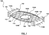
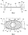
- FIG. 1 is a perspective view of a valve prosthesis 100 in an expanded, deployed configuration in accordance with an embodiment hereof, with FIGS. 2 and 3 being side and top views, respectively, of valve prosthesis 100 in the expanded, deployed configuration.
- FIG. 4 is a side view of a distal portion of a delivery catheter 440 with valve prosthesis 100 in a compressed, delivery configuration therein, and
- FIG. 5 is a distal end perspective view of valve prosthesis 100 in the compressed, delivery configuration within the delivery catheter.
- Valve prosthesis 100 includes a self-expanding frame 102 and a prosthetic valve component 104.
- Self-expanding frame 102 includes a valve receiving portion 106 defining a central opening 108 therethrough and first and second anchors 110A, 110B at opposing ends of the valve receiving portion.
- Valve receiving portion 106 is substantially planar and the first and second anchors 110A, 110B are oriented substantially perpendicular to the valve receiving portion when valve prosthesis 100 is in the expanded, deployed configuration of FIGS. 1-3 as will be discussed in more detail herein.
- Prosthetic valve component 104 is disposed within central opening 108 of valve receiving portion 106 and secured thereto.
- valve receiving portion 106 of frame 102 is a collapsible, compressible structure made of a material having resiliency or shape memory characteristics in order to return valve prosthesis 100 to the expanded, deployed configuration shown in FIGS. 1-3 upon release from a delivery device, such as delivery catheter 440. More particularly, in the expanded, deployed configuration of FIGS. 1-3 , valve receiving portion 106 has a mesh or lattice configuration with diamond-shaped openings 114 defined by the framework thereof, the diamond-shaped openings being shown by way of illustration and not limitation. Valve receiving portion 106 is substantially planar.
- substantially planar includes a structure that has a flat profile with a minimal thickness T that provides valve prosthesis 100 with a low ventricular profile that does not interfere with the left ventricular outflow tract.
- thickness T may be in the range of 0.025 mm to 5 mm.
- the substantially planar configuration of valve receiving portion 106 has opposing upstream and downstream surfaces 116, 118 that extend between opposing first and second ends 120A, 120B thereof, as best shown in the side view of FIG. 2 . As best shown in the top view of FIG.
- valve receiving portion 106 has an oblong shape with a longitudinal length L that is greater than a transverse width W that extends around prosthetic valve component 104 with a perimeter or border that defines an apposition surface 112 thereabout.
- width W may be in the range of 2.5 cm to 7.5 cm and length L may be in the range of 3 cm to 8 cm.
- "Oblong" as utilized herein includes a structure that has a rectangular shape or configuration, with angular or rounded corners, as well as an oval or other rounded shape or configuration. Apposition surface 112 about the perimeter of valve receiving portion 106 maintains apposition of valve prosthesis 100 against the native anatomy to provide a seal there against.
- sealing component 122 includes a first segment 124A of sealing or graft material coupled to one longitudinally extending edge of apposition surface 112 and a second segment 124B of sealing or graft material coupled to the opposing longitudinally extending edge of apposition surface 112.
- the sealing or graft material of sealing component 122 may be a low-porosity woven fabric, such as polyester, DACRON ® fabric, or PTFE.
- the sealing or graft material may be a knit or woven polyester, such as a polyester or PTFE knit, which can be utilized when it is desired to provide a medium for tissue ingrowth and the ability for the fabric to stretch to conform to a curved surface.
- Polyester velour fabrics may alternatively be used, such as when it is desired to provide a medium for tissue ingrowth on one side and a smooth surface on the other side.
- These and other appropriate cardiovascular fabrics are commercially available from Bard Peripheral Vascular, Inc. of Tempe, Ariz., for example.
- sealing or graft material of sealing component 122 may also be of a natural material such as pericardium or another membranous tissue such as intestinal submucosa or may be a polymer or compressible foam.
- sealing component 122 is omitted from the side view of FIG. 2 in order to more clearly illustrate the substantially planar configuration of valve receiving portion 106; however, segments 124A, 124B of sealing material are attached to the longitudinal edges of valve receiving portion 106 and extend between anchors 110A, 110B.
- Prosthetic valve component 104 is secured within valve receiving portion 106 and is configured as a one-way valve to allow blood flow in one direction and thereby regulate blood flow there through.
- prosthetic valve component 104 includes two valve leaflets 105A, 105B to form a bicuspid replacement valve that closes with pressure on the outflow and opens with pressure on the inflow.
- the prosthetic valve component may be a tricuspid replacement valve or may be a single leaflet replacement valve.
- the valve leaflets are sutured or otherwise securely and sealingly attached to an inner circumference of valve receiving portion 106 to span across central opening 108 thereof.
- central opening 108 is circular although the shape is shown by way of illustration and not limitation.
- Natural tissue for forming prosthetic valve leaflets for use in prosthetic valve component 104 may be obtained from, for example, heart valves, aortic roots, aortic walls, aortic leaflets, pericardial tissue, such as pericardial patches, bypass grafts, blood vessels, intestinal submucosal tissue, umbilical tissue and the like from humans or animals, such as tissue from bovine, equine or porcine origins.
- Synthetic materials suitable for use as prosthetic valve leaflets in embodiments hereof include DACRON ® polyester commercially available from Invista North America S.A.R.L. of Wilmington, DE, polyurethane, Gore-Tex or other cloth materials, nylon blends, polymeric materials, and vacuum deposition nitinol fabricated materials.
- One polymeric material from which the replacement valve leaflets can be made is an ultra-high molecular weight polyethylene material commercially available under the trade designation DYNEEMA from Royal DSM of the Netherlands.
- DYNEEMA ultra-high molecular weight polyethylene material commercially available under the trade designation DYNEEMA from Royal DSM of the Netherlands.
- Self-expanding frame 102 also includes first and second anchors 110A, 110B, which are disposed at opposing first and second ends 120A, 120B of valve receiving portion 106.
- First and second anchors 110A, 110B may also be referred to herein as distal and proximal anchors 110A, 110B, respectively.
- Anchors 110A, 110B operate to fix or secure valve prosthesis 100 within the native anatomy, and also operate to pin or push back the native leaflets so that the native leaflets do not interfere with operation of valve prosthesis 100.
- Each anchor 110A, 110B is a thin plate that has a substantially planar or flat body prior to implantation. In the expanded, deployed configuration of FIGS.
- each anchor curves or rounds with its respective end 120A, 120B and is oriented substantially perpendicular to valve receiving portion 106. More particularly, each anchor 110A, 110B may be rectangular, square, oval, rounded, or have another shape or configuration with opposing first and second edges 126, 128. When in the expanded, deployed configuration and oriented substantially perpendicular to valve receiving portion 106, first edge 126 of each anchor 110A, 110B extends outwardly beyond or upstream relative to upstream surface 116 of valve receiving portion 106 and second edge 128 of each anchor 110A, 110B extends outwardly beyond or downstream relative to downstream surface 118 of valve receiving portion 106.
- each anchor 110A, 100B is formed from a flexible material that conforms to native anatomy in situ and maintains apposition of valve prosthesis 100 against the native anatomy to provide a seal there against.
- anchors 110A, 110B may be formed from a material having resiliency or shape memory characteristics in order to return valve prosthesis 100 to the expanded, deployed configuration shown in FIG. 1-3 upon release from a delivery device, such as delivery catheter 440.
- each anchor 110A, 110B may no longer be flat or planar but may rather be curved or otherwise shaped to conform to the native anatomy.
- an adhesive (not shown) may be applied to an outermost surface of each anchor 110A, 110B to aid in securing the anchors to the surrounding native anatomy and maintaining apposition of valve prosthesis 100 against the native anatomy.
- Such an adhesive layer also aids acts as a sealant and aids in preventing paravalvular leakage in situ.
- valve receiving portion 106 and anchors 110A, 110B may be initially formed separately and then joined together by any means known to one of ordinary skill in the art such as, for instance, welding, gluing or suturing. In another embodiment, valve receiving portion 106 and anchors 110A, 110B may be initially formed as a single, integral component.
- a plurality of barbs or pins 130 may be coupled to each of first and second anchors 110A, 110B in order to assist in securing valve prosthesis 100 within the native valve annulus after implantation.
- Barbs 130 extend outwardly away from frame 102 and embed or press into the native anatomy.
- Barbs 130 may be coupled adjacent to the edges or perimeter of anchors 110A, 110B, as shown in FIG. 1 , or may be coupled to anchors 110A, 110B in any other suitable pattern or spacing.
- FIGS. 4 and 5 depict valve prosthesis 100 in its compressed, delivery configuration within delivery catheter 440.
- first and second anchors 110A, 110B are disposed or flattened under valve receiving portion 106 such that the entire valve prosthesis 100 is substantially planar or flattened.
- substantially flattened valve prosthesis 100 is then rolled or curled along its longitudinal axis L A (shown in FIG. 3 ) in order to compress or collapse valve prosthesis 100 into a smaller diameter suitable for transcatheter delivery.
- L A shown in FIG. 3
- the compressed, delivery configuration of valve prosthesis 100 is not limited to the rolled or curled configuration shown in FIGS. 4-5 but rather is only an exemplary method utilized to compress or collapse valve prosthesis 100 into a suitable profile for transcatheter delivery.
- Delivery catheter 440 includes an outer sheath 442 and an inner tube 444 slidingly disposed therein such that outer sheath 442 and inner tube 444 are moveable relative to each other. Although only a distal portion of delivery catheter 440 is shown, it will be understood by those of ordinary skill in the art that both outer sheath 442 and inner tube 444 extend to the proximal end of delivery catheter 440 to be assessable by the clinician.
- Valve prosthesis 100 in its compressed, delivery configuration is disposed within a distal portion of outer sheath 442, distal to a distal end 446 of inner tube 444, such that outer sheath 442 maintains the valve prosthesis in its compressed configuration during delivery.
- Valve prosthesis 100 abuts against and contacts distal end 446 of inner tube 444.
- inner tube 444 may define a lumen therethrough (not shown) for accommodating a guidewire.
- first anchor 110A and a portion of valve receiving portion 106 adjacent thereto unrolls or uncurls and self-expands to the expanded, deployed configuration of FIGS. 1-3 . More particularly, when first anchor 110A self-expands to the expanded, deployed configuration, the thin plate that forms first anchor 110A first unrolls or uncurls to resume a flattened or planar configuration.
- First anchor 110A which is now flattened but still disposed under valve receiving portion 106, then resumes its expanded, deployed configuration in which it extends substantially perpendicular to the valve receiving portion by flipping outwardly or rotating about end 120A of valve receiving portion 106.
- first anchor 110A engages and pins back the native anterior leaflet of the native mitral valve as will be explained in more detail below.
- Outer sheath 442 is then further proximally retracted to expose second anchor 110B and the remainder of valve receiving portion 106 such that they may unroll or uncurl and return or self-expand to the expanded, deployed configuration shown in FIGS. 1-3 .
- Second anchor 110B self-expands to the expanded, deployed configuration in the same manner as described above with respect to anchor 110A.
- the thin plate that forms second anchor 110B first unrolls or uncurls to resume a flattened or planar configuration, and then flips outwardly or rotates about end 120B of valve receiving portion 106 in order to resume its expanded, deployed configuration in which it extends substantially perpendicular to the valve receiving portion.
- valve receiving portion 106 is deployed to seat within the annulus of the native mitral valve and second anchor 110B engages and pins back the native posterior leaflet of the native mitral valve as will be explained in more detail below.
- inner tube 444 operates or functions as a retainer or stop that prevents valve prosthesis 100 from proximally retracting in conjunction with outer sheath 442.
- inner tube 444 may operate or function as a pusher tube which is distally advanced relative to outer sheath 442 to deploy valve prosthesis 100 as will be understood by one of ordinary skill in the art.
- FIGS. 6-10 illustrate a method of delivering and implanting valve prosthesis 100 to perform a heart valve replacement procedure, more particularly a mitral valve replacement, with minimal blood flow stoppage or interruption.
- FIG. 7 illustrating a cross-sectional view of a heart H, the heart H includes a left atrium LA, a left ventricle LV, a mitral valve MV and an aortic valve AV.
- Blood flow BF is depicted with directional arrows in FIG. 7 in the left atrium LA, into left ventricle LV through mitral valve MV, and into the aorta through aortic valve AV.
- Mitral valve MV is saddle-shaped and includes two native leaflets, posterior leaflet PL and anterior leaflet AL, and chordae tendineae CT extend within the left ventricle LV between the native leaflets of the mitral valve MV and the papillary muscles. More particularly, chordae tendineae CT are cord-like tendons that connect the medial papillary muscle MPM to the posterior leaflet PL of the mitral valve MV and connect the lateral papillary muscle LPM to the anterior leaflet AL of the mitral valve MV.
- a valve prosthesis 100 can be positioned in the area of a malfunctioning mitral valve MV in accordance with the invention, thereby replacing the mitral valve.
- the method of use described herein utilizes side access into the heart H and the deployed, expanded configuration of anchors 110A, 110B of valve prosthesis 100 to move or push the native leaflets of the mitral valve MV out of the mitral valve space so that they do not interfere with operation of the valve prosthesis.
- side access into the left atrium LA of the heart H and the substantially planar deployed, expanded configuration of valve receiving portion 106 of valve prosthesis 100 avoids or minimizes interference with the chordae tendineae CT present in the left ventricle LV of the heart H.
- FIGS. 6 and 7 illustrate an access zone or area AA for a left thoracotomy approach for a transcatheter or minimally invasive mitral valve replacement procedure.
- the left-sided approach offers some unique advantages, including a relatively shorter distance to the mitral valve over a right-sided approach as well as access within the mitral valve that allows the native valve leaflets to be moved or repositioned as will be described in more detail herein.
- a relatively short incision approximately 5-8 cm in length, may be made in the fourth, fifth, or sixth intercostal space.
- deflation of the left lung may be performed prior to and/or concurrent with introduction of delivery catheter 440, and the deflated left lung may be repositioned to expose the heart.
- An incision or opening may be formed in the pericardium, anteriorly or posteriorly to the phrenic nerve depending on the individual anatomy, and another incision or opening may be formed in a wall of the left atrium LA, slightly superior to an annulus of the native mitral valve MV, to provide exposure of the native mitral valve MV.
- Delivery catheter 440 having valve prosthesis 100 in a delivery configuration therein (not shown in FIG. 7 ) is advanced to the heart and through the incision of the left atrium LA until at least a distal portion of the delivery catheter, i.e., the distal portion containing valve prosthesis 100 contained therein, is disposed within or adjacent to the native mitral valve MV.
- delivery catheter 440 so positioned may have been tracked through a trocar or other introducer device (not shown) that has been inserted through purse-string sutures (not shown) previously placed in the left atrium LA.
- the purse-string sutures would be tightened around the trocar or other introducer device and a hemostasis valve would also be used to minimize blood leakage from the heart during the percutaneous replacement-valve implantation procedure, as would be understood by one of ordinary skill in the art.
- the proximal ends (not shown) of delivery catheter 440 and its components extend out of the body to be accessible by a clinician.
- first or distal anchor 110A of valve prosthesis 100 is released by retracting outer sheath 442 of delivery system 440 by a sufficient amount that this portion of the prosthesis is exposed as shown in FIG. 8 . Due to the self-expanding properties thereof, distal anchor 110A and a portion of valve receiving portion 106 adjacent thereto will expand radially outwardly relative to the sheath in which it was enclosed and return to the expanded, deployed configuration in which distal anchor 110A is oriented substantially perpendicular to valve receiving portion 106. During deployment of distal anchor 110A, second or proximal anchor 110B and the remainder of valve receiving portion 106 remain in the compressed configuration within outer sheath 442 of delivery catheter 440.
- Distal anchor 110A of valve prosthesis 100 is then secured to a wall of the heart as shown in FIG. 9 . More particularly, valve prosthesis 100 is distally advanced through distal advancement of inner tube 444 (not visible in the view of FIG. 9 ) until distal anchor 110A contacts or abuts against the wall of the heart. The anterior leaflet AL of the native mitral valve MV is pinned or captured between the wall of the heart and distal anchor 110A. When pressed against the wall of the heart, distal anchor 110A conforms to the wall of the heart and barbs 130 (visible in FIG. 8 but not visible in the view of FIG. 9 ) are pressed into the wall of the heart to assist in securing the prosthesis to the native anatomy. Alternatively, distal anchor 110A may contact the wall of the heart and be secured thereto upon release from delivery catheter 440 and self-expansion thereof without requiring additional positioning thereof.
- proximal anchor 110B releases the remainder of valve prosthesis 100, including second or proximal anchor 110B, from delivery catheter 440. Due to the self-expanding properties thereof, proximal anchor 110B and the remainder of valve receiving portion 106 expands radially outwardly relative to the sheath in which it was enclosed and return to the expanded, deployed configuration in which the proximal anchor is oriented substantially perpendicular to valve receiving portion 106 as shown in FIG. 10 (delivery catheter 440 is omitted from the view of FIG. 10 for sake of clarity).
- proximal anchor 110B Upon release from delivery catheter 440, proximal anchor 110B contacts the wall of the heart and is secured thereto, thereby pinning or capturing the posterior leaflet PL of the native mitral valve MV between the wall of the heart and proximal anchor 110B. When pressed against the wall of the heart, proximal anchor 110B conforms to the wall of the heart and barbs 130 are pressed into the wall of the heart to assist in securing the prosthesis to the native anatomy. All frame components, i.e., valve receiving portion 106 and anchors 110A, 110B, deploy or expand within the heart to be in apposition with the native mitral valve and functions as a replacement mitral valve.
- the frame components exert an apposition force that acts against the annulus of the native mitral valve and/or any heart structure in which they come in contact to seal against paravalvular leakage.
- delivery catheter 440 is removed from the heart with the purse-string sutures noted above being tightened thereafter to close the opening in the left atrium.
Claims (10)
- Prothèse valvulaire transcathéter (100) ayant une configuration de mise en place comprimée et une configuration expansée pour déploiement au sein d'une valve cardiaque native, la prothèse valvulaire (100) comprenant :un cadre auto-expansible (102) qui comporte- une partie de réception de valve (106) définissant une ouverture (108) à travers celle-ci, la partie de réception de valve (106) étant sensiblement plane avec une longueur longitudinale (L) qui est supérieure à une largeur transversale (W), et ayant des surfaces amont et aval opposées (116, 118) s'étendant entre des première et seconde extrémités opposées (120A, 120B) de la partie de réception de valve (106), et- des premier et second ancrages (110A, 110B) disposés respectivement au niveau des première et seconde extrémités opposées (120A, 120B) de la partie de réception de valve (106), dans laquelle les premier et second ancrages (110A, 110B) sont orientés sensiblement perpendiculaire aux surfaces amont et aval opposées (116, 118) de la partie de réception de valve (106) lorsque la prothèse valvulaire (100) se trouve dans la configuration expansée ;etun composant valvulaire prothétique (104) disposé au sein de l'ouverture (108) de la partie de réception de valve (106) et fixé à celle-ci.
- Prothèse valvulaire transcathéter (100) selon la revendication 1, comprenant en outre : un composant d'étanchéité (122) accouplé à au moins une partie du cadre (102).
- Prothèse valvulaire transcathéter (100) selon la revendication 2, dans laquelle le composant d'étanchéité (122) comporte un premier segment (124A) de matériau d'étanchéité fixé à un premier bord s'étendant longitudinalement de la partie de réception de valve (106) et un second segment (124B) de matériau d'étanchéité fixé à un second bord s'étendant longitudinalement opposé de la partie de réception de valve (106).
- Prothèse valvulaire transcathéter (100) selon la revendication 3, dans laquelle le composant d'étanchéité (122) est formé à partir d'un matériau choisi dans le groupe constitué de polyester, DACRON®, polymère, mousse compressible ou tissu péricardique.
- Prothèse valvulaire transcathéter (100) selon la revendication 1, dans laquelle chacun des premier et second ancrages (110A, 110B) est une plaque ayant un corps sensiblement plat avant l'implantation formée à partir d'un matériau souple qui est conçu pour se conformer à l'anatomie native in situ, et conçu pour maintenir une apposition de la prothèse valvulaire (100) contre l'anatomie native pour fournir une étanchéité contre celle-ci.
- Prothèse valvulaire transcathéter (100) selon la revendication 5, comprenant en outre : une pluralité de barbes (130) accouplées à chacun des premier et second ancrages (110A, 110B), les barbes (130) s'étendant vers l'extérieur à l'écart du cadre (102).
- Prothèse valvulaire transcathéter (100) selon la revendication 5, dans laquelle au moins des parties des premier et second ancrages (110A, 110B) sont conçues pour être disposées ou aplaties sous la partie de réception de valve (106) du cadre (102), de telle sorte que la prothèse valvulaire entière (100) est essentiellement plane ou aplatie, et la prothèse valvulaire sensiblement aplatie (100) est conçue pour être roulée
le long de son axe longitudinal (LA) lorsque la prothèse valvulaire (100) se trouve dans la configuration de mise en place comprimée. - Prothèse valvulaire transcathéter (100) selon l'une quelconque des revendications 1 à 7dans laquelle chacun des premier et second ancrages (110A, 110B) est une plaque mince, qui a un corps sensiblement plane ou plat avant implantation, avec des premier et second bords opposés (126, 128), etdans laquelle lorsque la prothèse valvulaire (100) se trouve dans la configuration expansée, les premier et second ancrages (110A, 110B) sont orientés de telle sorte que le premier bord (126) de chaque ancrage (110A, 110B) s'étend en amont de la surface amont (116) de la partie de réception de valve (106) et le second bord (128) de chaque ancrage (110A, 110B) s'étend en aval de la surface aval (118) de la partie de réception de valve (106).
- Prothèse valvulaire transcathéter (100) selon l'une quelconque des revendications 6 à 8, dans laquelle le premier ancrage (110A) est conçu de manière à êtrefixé à une paroi du coeur de sorte qu'un feuillet antérieur natif de la valve mitrale native est ainsi attaché entre la paroi du coeur et le premier ancrage (110A) ; dans laquelle, lorsqu'il est pressé contre la paroi du coeur, le premier ancrage (110A) est conforme à la paroi du coeur et des barbes (130) sont pressées dans la paroi du coeur pour aider à fixer la prothèse (100) au sein de l'anneau de valve native après l'implantation, etle second ancrage (110B) est conçu de manière à être fixé à la paroi du coeur de sorte qu'un feuillet postérieur natif de la valve mitrale native est ainsi attaché entre la paroi du coeur et le second ancrage (110B), dans laquelle lorsqu'il est pressé contre la paroi du coeur, le second ancrage (110B) se conforme à la paroi du coeur et des barbes (130) sont pressées dans la paroi du coeur pour aider à fixer la prothèse (100) au sein de l'anneau de valve native après l'implantation.
- Prothèse valvulaire transcathéter (100) selon la revendication 9, dans laquelle les premier et second ancrages (110A, 110B) sont conçus de manière à se conformer à la paroi du coeur lors de la fixation des premier et second ancrages (110A, 110B) de la prothèse valvulaire (100).
Priority Applications (1)
| Application Number | Priority Date | Filing Date | Title |
|---|---|---|---|
| EP23168756.7A EP4233794A3 (fr) | 2013-07-31 | 2014-07-02 | Prothèse de valve mitrale pour implantation valvulaire par cathétérisme |
Applications Claiming Priority (2)
| Application Number | Priority Date | Filing Date | Title |
|---|---|---|---|
| US13/955,177 US9895219B2 (en) | 2013-07-31 | 2013-07-31 | Mitral valve prosthesis for transcatheter valve implantation |
| PCT/US2014/045300 WO2015017075A1 (fr) | 2013-07-31 | 2014-07-02 | Prothèse de valve mitrale pour implantation valvulaire par cathétérisme |
Related Child Applications (2)
| Application Number | Title | Priority Date | Filing Date |
|---|---|---|---|
| EP23168756.7A Division-Into EP4233794A3 (fr) | 2013-07-31 | 2014-07-02 | Prothèse de valve mitrale pour implantation valvulaire par cathétérisme |
| EP23168756.7A Division EP4233794A3 (fr) | 2013-07-31 | 2014-07-02 | Prothèse de valve mitrale pour implantation valvulaire par cathétérisme |
Publications (2)
| Publication Number | Publication Date |
|---|---|
| EP3027143A1 EP3027143A1 (fr) | 2016-06-08 |
| EP3027143B1 true EP3027143B1 (fr) | 2023-06-21 |
Family
ID=51225898
Family Applications (2)
| Application Number | Title | Priority Date | Filing Date |
|---|---|---|---|
| EP14744237.0A Active EP3027143B1 (fr) | 2013-07-31 | 2014-07-02 | Prothèse de valve mitrale pour implantation valvulaire par cathétérisme |
| EP23168756.7A Pending EP4233794A3 (fr) | 2013-07-31 | 2014-07-02 | Prothèse de valve mitrale pour implantation valvulaire par cathétérisme |
Family Applications After (1)
| Application Number | Title | Priority Date | Filing Date |
|---|---|---|---|
| EP23168756.7A Pending EP4233794A3 (fr) | 2013-07-31 | 2014-07-02 | Prothèse de valve mitrale pour implantation valvulaire par cathétérisme |
Country Status (3)
| Country | Link |
|---|---|
| US (4) | US9895219B2 (fr) |
| EP (2) | EP3027143B1 (fr) |
| WO (1) | WO2015017075A1 (fr) |
Families Citing this family (62)
| Publication number | Priority date | Publication date | Assignee | Title |
|---|---|---|---|---|
| US8366767B2 (en) | 2009-03-30 | 2013-02-05 | Causper Medical Inc. | Methods and devices for transapical delivery of a sutureless valve prosthesis |
| US9730790B2 (en) | 2009-09-29 | 2017-08-15 | Edwards Lifesciences Cardiaq Llc | Replacement valve and method |
| CA3035048C (fr) | 2010-12-23 | 2021-05-04 | Mark Deem | Systeme de reparation et remplacement de valvule mitrale |
| AU2012272855C1 (en) | 2011-06-21 | 2018-04-05 | Twelve, Inc. | Prosthetic heart valve devices and associated systems and methods |
| US9039757B2 (en) | 2011-10-19 | 2015-05-26 | Twelve, Inc. | Prosthetic heart valve devices, prosthetic mitral valves and associated systems and methods |
| US9763780B2 (en) | 2011-10-19 | 2017-09-19 | Twelve, Inc. | Devices, systems and methods for heart valve replacement |
| US9655722B2 (en) | 2011-10-19 | 2017-05-23 | Twelve, Inc. | Prosthetic heart valve devices, prosthetic mitral valves and associated systems and methods |
| US11202704B2 (en) | 2011-10-19 | 2021-12-21 | Twelve, Inc. | Prosthetic heart valve devices, prosthetic mitral valves and associated systems and methods |
| EP2750630B1 (fr) | 2011-10-19 | 2021-06-30 | Twelve, Inc. | Dispositif de remplacement de valvule cardiaque |
| US10016271B2 (en) | 2011-10-19 | 2018-07-10 | Twelve, Inc. | Prosthetic heart valve devices, prosthetic mitral valves and associated systems and methods |
| US9579198B2 (en) | 2012-03-01 | 2017-02-28 | Twelve, Inc. | Hydraulic delivery systems for prosthetic heart valve devices and associated methods |
| EP2967810B1 (fr) | 2013-03-14 | 2020-04-22 | Suzhou Jiecheng Medical Technology Co., Ltd. | Dispositifs de protection contre l'embolie |
| US9681951B2 (en) | 2013-03-14 | 2017-06-20 | Edwards Lifesciences Cardiaq Llc | Prosthesis with outer skirt and anchors |
| US11406497B2 (en) | 2013-03-14 | 2022-08-09 | Jc Medical, Inc. | Heart valve prosthesis |
| US11259923B2 (en) | 2013-03-14 | 2022-03-01 | Jc Medical, Inc. | Methods and devices for delivery of a prosthetic valve |
| CN108294846A (zh) | 2013-05-20 | 2018-07-20 | 托尔福公司 | 可植入心脏瓣膜装置、二尖瓣修复装置以及相关系统和方法 |
| US9895219B2 (en) * | 2013-07-31 | 2018-02-20 | Medtronic Vascular Galway | Mitral valve prosthesis for transcatheter valve implantation |
| CN107920895B (zh) | 2015-08-21 | 2020-06-26 | 托尔福公司 | 可植入心脏瓣膜装置、二尖瓣修复装置以及相关系统和方法 |
| MA43173A (fr) | 2015-11-06 | 2018-09-12 | Micor Ltd | Prothèse de valvule mitrale |
| CN109069272A (zh) | 2016-04-29 | 2018-12-21 | 美敦力瓦斯科尔勒公司 | 具有带系绳的锚定件的假体心脏瓣膜设备以及相关联的系统和方法 |
| US11241307B2 (en) | 2016-10-13 | 2022-02-08 | Boston Scientific Scimed, Inc. | Replacement heart valve with diaphragm |
| US10653523B2 (en) | 2017-01-19 | 2020-05-19 | 4C Medical Technologies, Inc. | Systems, methods and devices for delivery systems, methods and devices for implanting prosthetic heart valves |
| US10561495B2 (en) | 2017-01-24 | 2020-02-18 | 4C Medical Technologies, Inc. | Systems, methods and devices for two-step delivery and implantation of prosthetic heart valve |
| US10905550B2 (en) | 2017-02-01 | 2021-02-02 | Medtronic Vascular, Inc. | Heart valve prostheses including torque anchoring mechanisms and delivery devices for the heart valve prostheses |
| US10433961B2 (en) | 2017-04-18 | 2019-10-08 | Twelve, Inc. | Delivery systems with tethers for prosthetic heart valve devices and associated methods |
| US10575950B2 (en) | 2017-04-18 | 2020-03-03 | Twelve, Inc. | Hydraulic systems for delivering prosthetic heart valve devices and associated methods |
| US10702378B2 (en) | 2017-04-18 | 2020-07-07 | Twelve, Inc. | Prosthetic heart valve device and associated systems and methods |
| US10792151B2 (en) | 2017-05-11 | 2020-10-06 | Twelve, Inc. | Delivery systems for delivering prosthetic heart valve devices and associated methods |
| US10646338B2 (en) | 2017-06-02 | 2020-05-12 | Twelve, Inc. | Delivery systems with telescoping capsules for deploying prosthetic heart valve devices and associated methods |
| US10709591B2 (en) | 2017-06-06 | 2020-07-14 | Twelve, Inc. | Crimping device and method for loading stents and prosthetic heart valves |
| US10786352B2 (en) | 2017-07-06 | 2020-09-29 | Twelve, Inc. | Prosthetic heart valve devices and associated systems and methods |
| US10729541B2 (en) | 2017-07-06 | 2020-08-04 | Twelve, Inc. | Prosthetic heart valve devices and associated systems and methods |
| US11666444B2 (en) * | 2017-08-03 | 2023-06-06 | The Regents Of The University Of California | Atrial cage for placement, securing and anchoring of atrioventricular valves |
| CN210301305U (zh) | 2018-01-07 | 2020-04-14 | 苏州杰成医疗科技有限公司 | 心脏瓣膜假体递送系统 |
| CN210301304U (zh) | 2018-01-07 | 2020-04-14 | 苏州杰成医疗科技有限公司 | 假体心脏瓣膜输送系统 |
| EP4289400A2 (fr) * | 2018-02-15 | 2023-12-13 | Tricares SAS | Endoprothèse et prothèse de valvule cardiaque de remplacement présentant des caractéristiques de fixation améliorées |
| WO2019195860A2 (fr) | 2018-04-04 | 2019-10-10 | Vdyne, Llc | Dispositifs et procédés d'ancrage d'une valvule cardiaque transcathéter |
| US20190365538A1 (en) * | 2018-06-04 | 2019-12-05 | 4C Medical Technologies, Inc. | Devices, systems and methods for preventing prolapse of native cardiac valve leaflets |
| US11224418B2 (en) * | 2018-06-15 | 2022-01-18 | Edwards Lifesciences Corporation | Papillary muscle approximation pads |
| US10779937B2 (en) | 2018-06-22 | 2020-09-22 | Vdyne, Inc. | Transcatheter heart valve with plication window and tissue anchors |
| US11857441B2 (en) | 2018-09-04 | 2024-01-02 | 4C Medical Technologies, Inc. | Stent loading device |
| WO2020061124A1 (fr) * | 2018-09-20 | 2020-03-26 | Vdyne, Llc | Valvules cardiaques prothétiques pouvant être implantées transcathéter et procédés d'administration |
| US11071627B2 (en) * | 2018-10-18 | 2021-07-27 | Vdyne, Inc. | Orthogonally delivered transcatheter heart valve frame for valve in valve prosthesis |
| US11344413B2 (en) | 2018-09-20 | 2022-05-31 | Vdyne, Inc. | Transcatheter deliverable prosthetic heart valves and methods of delivery |
| US10595994B1 (en) | 2018-09-20 | 2020-03-24 | Vdyne, Llc | Side-delivered transcatheter heart valve replacement |
| US11278437B2 (en) | 2018-12-08 | 2022-03-22 | Vdyne, Inc. | Compression capable annular frames for side delivery of transcatheter heart valve replacement |
| US10321995B1 (en) | 2018-09-20 | 2019-06-18 | Vdyne, Llc | Orthogonally delivered transcatheter heart valve replacement |
| US11109969B2 (en) * | 2018-10-22 | 2021-09-07 | Vdyne, Inc. | Guidewire delivery of transcatheter heart valve |
| US11253359B2 (en) | 2018-12-20 | 2022-02-22 | Vdyne, Inc. | Proximal tab for side-delivered transcatheter heart valves and methods of delivery |
| US10653522B1 (en) * | 2018-12-20 | 2020-05-19 | Vdyne, Inc. | Proximal tab for side-delivered transcatheter heart valve prosthesis |
| US11185409B2 (en) | 2019-01-26 | 2021-11-30 | Vdyne, Inc. | Collapsible inner flow control component for side-delivered transcatheter heart valve prosthesis |
| US11273032B2 (en) | 2019-01-26 | 2022-03-15 | Vdyne, Inc. | Collapsible inner flow control component for side-deliverable transcatheter heart valve prosthesis |
| WO2020181154A2 (fr) | 2019-03-05 | 2020-09-10 | Vdyne, Inc. | Dispositifs de régulation de régurgitation tricuspide pour prothèse de valvule cardiaque transcathéter orthogonale |
| US11076956B2 (en) | 2019-03-14 | 2021-08-03 | Vdyne, Inc. | Proximal, distal, and anterior anchoring tabs for side-delivered transcatheter mitral valve prosthesis |
| US11173027B2 (en) | 2019-03-14 | 2021-11-16 | Vdyne, Inc. | Side-deliverable transcatheter prosthetic valves and methods for delivering and anchoring the same |
| US10631983B1 (en) | 2019-03-14 | 2020-04-28 | Vdyne, Inc. | Distal subannular anchoring tab for side-delivered transcatheter valve prosthesis |
| US10758346B1 (en) | 2019-03-14 | 2020-09-01 | Vdyne, Inc. | A2 clip for side-delivered transcatheter mitral valve prosthesis |
| JP2022530764A (ja) | 2019-05-04 | 2022-07-01 | ブイダイン,インコーポレイテッド | 生来の弁輪での側方送達される人工心臓弁を展開するための締め付けデバイス及び方法 |
| EP4017442A4 (fr) | 2019-08-20 | 2023-07-26 | Vdyne, Inc. | Dispositifs d'administration et de récupération et procédés pour valvules prothétiques transcathéter à pose latérale |
| CN114630665A (zh) | 2019-08-26 | 2022-06-14 | 维迪内股份有限公司 | 可侧面输送的经导管假体瓣膜及其输送和锚定方法 |
| US11234813B2 (en) | 2020-01-17 | 2022-02-01 | Vdyne, Inc. | Ventricular stability elements for side-deliverable prosthetic heart valves and methods of delivery |
| US11931253B2 (en) | 2020-01-31 | 2024-03-19 | 4C Medical Technologies, Inc. | Prosthetic heart valve delivery system: ball-slide attachment |
Citations (1)
| Publication number | Priority date | Publication date | Assignee | Title |
|---|---|---|---|---|
| EP2509538B1 (fr) * | 2009-12-08 | 2017-09-20 | Avalon Medical Ltd. | Dispositif et système de remplacement de valvule mitrale transcathéter |
Family Cites Families (28)
| Publication number | Priority date | Publication date | Assignee | Title |
|---|---|---|---|---|
| AR206762A1 (es) * | 1976-01-01 | 1976-08-13 | Pisanu A | Bioprotesis de bajo perfil derivada de la valvula aortica heterologa de porcino |
| US5972030A (en) | 1993-02-22 | 1999-10-26 | Heartport, Inc. | Less-invasive devices and methods for treatment of cardiac valves |
| US6010531A (en) | 1993-02-22 | 2000-01-04 | Heartport, Inc. | Less-invasive devices and methods for cardiac valve surgery |
| DE4316971A1 (de) | 1993-05-21 | 1994-11-24 | Georg Dr Berg | Ventileinrichtung zum Einsetzen in ein Hohlorgan, ein Gefäß oder dergleichen |
| US5957949A (en) | 1997-05-01 | 1999-09-28 | World Medical Manufacturing Corp. | Percutaneous placement valve stent |
| US6190311B1 (en) * | 1997-05-02 | 2001-02-20 | Cardiothoracic Systems, Inc. | Retractor and instrument platform for a less invasive cardiovascular surgical procedure |
| US6425916B1 (en) * | 1999-02-10 | 2002-07-30 | Michi E. Garrison | Methods and devices for implanting cardiac valves |
| DE10010073B4 (de) | 2000-02-28 | 2005-12-22 | Fraunhofer-Gesellschaft zur Förderung der angewandten Forschung e.V. | Verankerung für implantierbare Herzklappenprothesen |
| WO2004030568A2 (fr) * | 2002-10-01 | 2004-04-15 | Ample Medical, Inc. | Dispositifs, systemes et procedes pour ajouter, reparer ou remplacer un feuillet de valvule cardiaque natif |
| US6974476B2 (en) * | 2003-05-05 | 2005-12-13 | Rex Medical, L.P. | Percutaneous aortic valve |
| US7374571B2 (en) | 2001-03-23 | 2008-05-20 | Edwards Lifesciences Corporation | Rolled minimally-invasive heart valves and methods of manufacture |
| EP1562522B1 (fr) * | 2002-10-01 | 2008-12-31 | Ample Medical, Inc. | Dispositifs and systemes pour remodeler un anneau de valvule cardiaque |
| US20070073387A1 (en) * | 2004-02-27 | 2007-03-29 | Forster David C | Prosthetic Heart Valves, Support Structures And Systems And Methods For Implanting The Same |
| NL1025830C2 (nl) * | 2004-03-26 | 2005-02-22 | Eric Berreklouw | Samenstel omvattende een ring voor bevestiging in een door lichaamsweefsel omgeven doorgang alsmede een applicator voor het in de doorgang plaatsen van de ring. |
| DK1850796T3 (en) * | 2005-02-18 | 2016-01-18 | Cleveland Clinic Foundation | DEVICE FOR REPLACEMENT OF A HEART VALVE |
| US7935144B2 (en) | 2006-10-19 | 2011-05-03 | Direct Flow Medical, Inc. | Profile reduction of valve implant |
| EP2091466A2 (fr) | 2006-11-17 | 2009-08-26 | St.Jude Medical, Inc | Structure de valvule cardiaque prosthétique, et procédés associés |
| US8105375B2 (en) * | 2007-01-19 | 2012-01-31 | The Cleveland Clinic Foundation | Method for implanting a cardiovascular valve |
| US9402720B2 (en) * | 2009-01-12 | 2016-08-02 | Valve Medical Ltd. | Modular percutaneous valve structure and delivery method |
| US9011522B2 (en) | 2009-04-10 | 2015-04-21 | Lon Sutherland ANNEST | Device and method for temporary or permanent suspension of an implantable scaffolding containing an orifice for placement of a prosthetic or bio-prosthetic valve |
| US8449599B2 (en) * | 2009-12-04 | 2013-05-28 | Edwards Lifesciences Corporation | Prosthetic valve for replacing mitral valve |
| CA3035048C (fr) | 2010-12-23 | 2021-05-04 | Mark Deem | Systeme de reparation et remplacement de valvule mitrale |
| US8852272B2 (en) * | 2011-08-05 | 2014-10-07 | Mitraltech Ltd. | Techniques for percutaneous mitral valve replacement and sealing |
| WO2013021374A2 (fr) * | 2011-08-05 | 2013-02-14 | Mitraltech Ltd. | Techniques pour le remplacement et la fixation percutanés d'une valvule mitrale |
| AU2012299311B2 (en) | 2011-08-11 | 2016-03-03 | Tendyne Holdings, Inc. | Improvements for prosthetic valves and related inventions |
| WO2013076724A2 (fr) | 2011-11-21 | 2013-05-30 | Mor Research Applications Ltd. | Dispositif destiné à être placé dans l'anneau tricuspidien |
| US8926694B2 (en) * | 2012-03-28 | 2015-01-06 | Medtronic Vascular Galway Limited | Dual valve prosthesis for transcatheter valve implantation |
| US9895219B2 (en) * | 2013-07-31 | 2018-02-20 | Medtronic Vascular Galway | Mitral valve prosthesis for transcatheter valve implantation |
-
2013
- 2013-07-31 US US13/955,177 patent/US9895219B2/en active Active
-
2014
- 2014-07-02 EP EP14744237.0A patent/EP3027143B1/fr active Active
- 2014-07-02 WO PCT/US2014/045300 patent/WO2015017075A1/fr active Application Filing
- 2014-07-02 EP EP23168756.7A patent/EP4233794A3/fr active Pending
-
2018
- 2018-01-17 US US15/873,595 patent/US10813750B2/en active Active
-
2020
- 2020-10-19 US US17/073,534 patent/US11376120B2/en active Active
-
2022
- 2022-06-02 US US17/830,775 patent/US20220287829A1/en active Pending
Patent Citations (1)
| Publication number | Priority date | Publication date | Assignee | Title |
|---|---|---|---|---|
| EP2509538B1 (fr) * | 2009-12-08 | 2017-09-20 | Avalon Medical Ltd. | Dispositif et système de remplacement de valvule mitrale transcathéter |
Also Published As
| Publication number | Publication date |
|---|---|
| US20220287829A1 (en) | 2022-09-15 |
| WO2015017075A1 (fr) | 2015-02-05 |
| US9895219B2 (en) | 2018-02-20 |
| US10813750B2 (en) | 2020-10-27 |
| EP4233794A2 (fr) | 2023-08-30 |
| US20150039081A1 (en) | 2015-02-05 |
| US11376120B2 (en) | 2022-07-05 |
| US20210045867A1 (en) | 2021-02-18 |
| EP3027143A1 (fr) | 2016-06-08 |
| EP4233794A3 (fr) | 2023-09-06 |
| US20180153685A1 (en) | 2018-06-07 |
Similar Documents
| Publication | Publication Date | Title |
|---|---|---|
| US11376120B2 (en) | Mitral valve prosthesis for transcatheter valve implantation | |
| EP3506855B1 (fr) | Prothèse de valve cardiaque et bride de support séparée pour la fixation à celle-ci | |
| US11723764B2 (en) | Valve prostheses having an integral centering mechanism and methods of use thereof | |
| US10219896B2 (en) | Segmented transcatheter valve prosthesis having an unsupported valve segment | |
| EP2964152B1 (fr) | Prothèse pour implantation transcathéter de valvule | |
| EP3311778B1 (fr) | Prothèse de valve double pour implantation de valve transcathéter | |
| US9295547B2 (en) | Prosthesis for transcatheter valve implantation | |
| US9023098B2 (en) | Dual valve prosthesis for transcatheter valve implantation | |
| AU2016370367A1 (en) | Delivery system having retractable wires as a coupling mechanism and a deployment mechanism for a self-expanding prosthesis | |
| AU2016371525A1 (en) | Delivery system having retractable wires as a coupling mechanism and a deployment mechanism for a self-expanding prosthesis | |
| EP2967853A1 (fr) | Prothèse de valvule cardiaque |
Legal Events
| Date | Code | Title | Description |
|---|---|---|---|
| PUAI | Public reference made under article 153(3) epc to a published international application that has entered the european phase |
Free format text: ORIGINAL CODE: 0009012 |
|
| 17P | Request for examination filed |
Effective date: 20160226 |
|
| AK | Designated contracting states |
Kind code of ref document: A1 Designated state(s): AL AT BE BG CH CY CZ DE DK EE ES FI FR GB GR HR HU IE IS IT LI LT LU LV MC MK MT NL NO PL PT RO RS SE SI SK SM TR |
|
| AX | Request for extension of the european patent |
Extension state: BA ME |
|
| DAX | Request for extension of the european patent (deleted) | ||
| STAA | Information on the status of an ep patent application or granted ep patent |
Free format text: STATUS: EXAMINATION IS IN PROGRESS |
|
| 17Q | First examination report despatched |
Effective date: 20191024 |
|
| STAA | Information on the status of an ep patent application or granted ep patent |
Free format text: STATUS: EXAMINATION IS IN PROGRESS |
|
| RAP1 | Party data changed (applicant data changed or rights of an application transferred) |
Owner name: MEDTRONIC VASCULAR GALWAY |
|
| GRAP | Despatch of communication of intention to grant a patent |
Free format text: ORIGINAL CODE: EPIDOSNIGR1 |
|
| STAA | Information on the status of an ep patent application or granted ep patent |
Free format text: STATUS: GRANT OF PATENT IS INTENDED |
|
| INTG | Intention to grant announced |
Effective date: 20230117 |
|
| GRAS | Grant fee paid |
Free format text: ORIGINAL CODE: EPIDOSNIGR3 |
|
| GRAA | (expected) grant |
Free format text: ORIGINAL CODE: 0009210 |
|
| STAA | Information on the status of an ep patent application or granted ep patent |
Free format text: STATUS: THE PATENT HAS BEEN GRANTED |
|
| AK | Designated contracting states |
Kind code of ref document: B1 Designated state(s): AL AT BE BG CH CY CZ DE DK EE ES FI FR GB GR HR HU IE IS IT LI LT LU LV MC MK MT NL NO PL PT RO RS SE SI SK SM TR |
|
| REG | Reference to a national code |
Ref country code: CH Ref legal event code: EP |
|
| REG | Reference to a national code |
Ref country code: DE Ref legal event code: R096 Ref document number: 602014087411 Country of ref document: DE |
|
| REG | Reference to a national code |
Ref country code: AT Ref legal event code: REF Ref document number: 1580364 Country of ref document: AT Kind code of ref document: T Effective date: 20230715 |
|
| REG | Reference to a national code |
Ref country code: IE Ref legal event code: FG4D |
|
| REG | Reference to a national code |
Ref country code: LT Ref legal event code: MG9D |
|
| REG | Reference to a national code |
Ref country code: NL Ref legal event code: MP Effective date: 20230621 |
|
| PG25 | Lapsed in a contracting state [announced via postgrant information from national office to epo] |
Ref country code: SE Free format text: LAPSE BECAUSE OF FAILURE TO SUBMIT A TRANSLATION OF THE DESCRIPTION OR TO PAY THE FEE WITHIN THE PRESCRIBED TIME-LIMIT Effective date: 20230621 Ref country code: NO Free format text: LAPSE BECAUSE OF FAILURE TO SUBMIT A TRANSLATION OF THE DESCRIPTION OR TO PAY THE FEE WITHIN THE PRESCRIBED TIME-LIMIT Effective date: 20230921 |
|
| PGFP | Annual fee paid to national office [announced via postgrant information from national office to epo] |
Ref country code: IE Payment date: 20230724 Year of fee payment: 10 |
|
| REG | Reference to a national code |
Ref country code: AT Ref legal event code: MK05 Ref document number: 1580364 Country of ref document: AT Kind code of ref document: T Effective date: 20230621 |
|
| PG25 | Lapsed in a contracting state [announced via postgrant information from national office to epo] |
Ref country code: RS Free format text: LAPSE BECAUSE OF FAILURE TO SUBMIT A TRANSLATION OF THE DESCRIPTION OR TO PAY THE FEE WITHIN THE PRESCRIBED TIME-LIMIT Effective date: 20230621 Ref country code: NL Free format text: LAPSE BECAUSE OF FAILURE TO SUBMIT A TRANSLATION OF THE DESCRIPTION OR TO PAY THE FEE WITHIN THE PRESCRIBED TIME-LIMIT Effective date: 20230621 Ref country code: LV Free format text: LAPSE BECAUSE OF FAILURE TO SUBMIT A TRANSLATION OF THE DESCRIPTION OR TO PAY THE FEE WITHIN THE PRESCRIBED TIME-LIMIT Effective date: 20230621 Ref country code: LT Free format text: LAPSE BECAUSE OF FAILURE TO SUBMIT A TRANSLATION OF THE DESCRIPTION OR TO PAY THE FEE WITHIN THE PRESCRIBED TIME-LIMIT Effective date: 20230621 Ref country code: HR Free format text: LAPSE BECAUSE OF FAILURE TO SUBMIT A TRANSLATION OF THE DESCRIPTION OR TO PAY THE FEE WITHIN THE PRESCRIBED TIME-LIMIT Effective date: 20230621 Ref country code: GR Free format text: LAPSE BECAUSE OF FAILURE TO SUBMIT A TRANSLATION OF THE DESCRIPTION OR TO PAY THE FEE WITHIN THE PRESCRIBED TIME-LIMIT Effective date: 20230922 |
|
| PGFP | Annual fee paid to national office [announced via postgrant information from national office to epo] |
Ref country code: DE Payment date: 20230720 Year of fee payment: 10 |
|
| PG25 | Lapsed in a contracting state [announced via postgrant information from national office to epo] |
Ref country code: FI Free format text: LAPSE BECAUSE OF FAILURE TO SUBMIT A TRANSLATION OF THE DESCRIPTION OR TO PAY THE FEE WITHIN THE PRESCRIBED TIME-LIMIT Effective date: 20230621 |
|
| PG25 | Lapsed in a contracting state [announced via postgrant information from national office to epo] |
Ref country code: SK Free format text: LAPSE BECAUSE OF FAILURE TO SUBMIT A TRANSLATION OF THE DESCRIPTION OR TO PAY THE FEE WITHIN THE PRESCRIBED TIME-LIMIT Effective date: 20230621 |
|
| PG25 | Lapsed in a contracting state [announced via postgrant information from national office to epo] |
Ref country code: ES Free format text: LAPSE BECAUSE OF FAILURE TO SUBMIT A TRANSLATION OF THE DESCRIPTION OR TO PAY THE FEE WITHIN THE PRESCRIBED TIME-LIMIT Effective date: 20230621 |
|
| PG25 | Lapsed in a contracting state [announced via postgrant information from national office to epo] |
Ref country code: IS Free format text: LAPSE BECAUSE OF FAILURE TO SUBMIT A TRANSLATION OF THE DESCRIPTION OR TO PAY THE FEE WITHIN THE PRESCRIBED TIME-LIMIT Effective date: 20231021 |
|
| PG25 | Lapsed in a contracting state [announced via postgrant information from national office to epo] |
Ref country code: SM Free format text: LAPSE BECAUSE OF FAILURE TO SUBMIT A TRANSLATION OF THE DESCRIPTION OR TO PAY THE FEE WITHIN THE PRESCRIBED TIME-LIMIT Effective date: 20230621 Ref country code: SK Free format text: LAPSE BECAUSE OF FAILURE TO SUBMIT A TRANSLATION OF THE DESCRIPTION OR TO PAY THE FEE WITHIN THE PRESCRIBED TIME-LIMIT Effective date: 20230621 Ref country code: RO Free format text: LAPSE BECAUSE OF FAILURE TO SUBMIT A TRANSLATION OF THE DESCRIPTION OR TO PAY THE FEE WITHIN THE PRESCRIBED TIME-LIMIT Effective date: 20230621 Ref country code: PT Free format text: LAPSE BECAUSE OF FAILURE TO SUBMIT A TRANSLATION OF THE DESCRIPTION OR TO PAY THE FEE WITHIN THE PRESCRIBED TIME-LIMIT Effective date: 20231023 Ref country code: IS Free format text: LAPSE BECAUSE OF FAILURE TO SUBMIT A TRANSLATION OF THE DESCRIPTION OR TO PAY THE FEE WITHIN THE PRESCRIBED TIME-LIMIT Effective date: 20231021 Ref country code: ES Free format text: LAPSE BECAUSE OF FAILURE TO SUBMIT A TRANSLATION OF THE DESCRIPTION OR TO PAY THE FEE WITHIN THE PRESCRIBED TIME-LIMIT Effective date: 20230621 Ref country code: EE Free format text: LAPSE BECAUSE OF FAILURE TO SUBMIT A TRANSLATION OF THE DESCRIPTION OR TO PAY THE FEE WITHIN THE PRESCRIBED TIME-LIMIT Effective date: 20230621 Ref country code: CZ Free format text: LAPSE BECAUSE OF FAILURE TO SUBMIT A TRANSLATION OF THE DESCRIPTION OR TO PAY THE FEE WITHIN THE PRESCRIBED TIME-LIMIT Effective date: 20230621 Ref country code: AT Free format text: LAPSE BECAUSE OF FAILURE TO SUBMIT A TRANSLATION OF THE DESCRIPTION OR TO PAY THE FEE WITHIN THE PRESCRIBED TIME-LIMIT Effective date: 20230621 |
|
| PG25 | Lapsed in a contracting state [announced via postgrant information from national office to epo] |
Ref country code: PL Free format text: LAPSE BECAUSE OF FAILURE TO SUBMIT A TRANSLATION OF THE DESCRIPTION OR TO PAY THE FEE WITHIN THE PRESCRIBED TIME-LIMIT Effective date: 20230621 |
|
| REG | Reference to a national code |
Ref country code: CH Ref legal event code: PL |
|
| PG25 | Lapsed in a contracting state [announced via postgrant information from national office to epo] |
Ref country code: MC Free format text: LAPSE BECAUSE OF FAILURE TO SUBMIT A TRANSLATION OF THE DESCRIPTION OR TO PAY THE FEE WITHIN THE PRESCRIBED TIME-LIMIT Effective date: 20230621 |
|
| REG | Reference to a national code |
Ref country code: BE Ref legal event code: MM Effective date: 20230731 |
|
| PG25 | Lapsed in a contracting state [announced via postgrant information from national office to epo] |
Ref country code: LU Free format text: LAPSE BECAUSE OF NON-PAYMENT OF DUE FEES Effective date: 20230702 |
|
| PG25 | Lapsed in a contracting state [announced via postgrant information from national office to epo] |
Ref country code: MC Free format text: LAPSE BECAUSE OF FAILURE TO SUBMIT A TRANSLATION OF THE DESCRIPTION OR TO PAY THE FEE WITHIN THE PRESCRIBED TIME-LIMIT Effective date: 20230621 Ref country code: LU Free format text: LAPSE BECAUSE OF NON-PAYMENT OF DUE FEES Effective date: 20230702 |