EP3026754A1 - Module compact d'excitation radiofréquence à cinématique intégrée et antenne compacte biaxe comportant au moins un tel module compact - Google Patents
Module compact d'excitation radiofréquence à cinématique intégrée et antenne compacte biaxe comportant au moins un tel module compact Download PDFInfo
- Publication number
- EP3026754A1 EP3026754A1 EP15195396.5A EP15195396A EP3026754A1 EP 3026754 A1 EP3026754 A1 EP 3026754A1 EP 15195396 A EP15195396 A EP 15195396A EP 3026754 A1 EP3026754 A1 EP 3026754A1
- Authority
- EP
- European Patent Office
- Prior art keywords
- compact
- rotary
- rotary joint
- exciter
- excitation module
- Prior art date
- Legal status (The legal status is an assumption and is not a legal conclusion. Google has not performed a legal analysis and makes no representation as to the accuracy of the status listed.)
- Withdrawn
Links
- 230000005284 excitation Effects 0.000 title claims abstract description 42
- 238000010586 diagram Methods 0.000 description 10
- 230000010287 polarization Effects 0.000 description 5
- 230000008878 coupling Effects 0.000 description 3
- 238000010168 coupling process Methods 0.000 description 3
- 238000005859 coupling reaction Methods 0.000 description 3
- 230000006798 recombination Effects 0.000 description 3
- 238000005215 recombination Methods 0.000 description 3
- 230000005540 biological transmission Effects 0.000 description 2
- 230000000295 complement effect Effects 0.000 description 1
- 238000005516 engineering process Methods 0.000 description 1
- 238000002513 implantation Methods 0.000 description 1
Images






Classifications
-
- H—ELECTRICITY
- H01—ELECTRIC ELEMENTS
- H01P—WAVEGUIDES; RESONATORS, LINES, OR OTHER DEVICES OF THE WAVEGUIDE TYPE
- H01P1/00—Auxiliary devices
- H01P1/06—Movable joints, e.g. rotating joints
- H01P1/062—Movable joints, e.g. rotating joints the relative movement being a rotation
-
- H—ELECTRICITY
- H01—ELECTRIC ELEMENTS
- H01P—WAVEGUIDES; RESONATORS, LINES, OR OTHER DEVICES OF THE WAVEGUIDE TYPE
- H01P1/00—Auxiliary devices
- H01P1/06—Movable joints, e.g. rotating joints
- H01P1/062—Movable joints, e.g. rotating joints the relative movement being a rotation
- H01P1/066—Movable joints, e.g. rotating joints the relative movement being a rotation with an unlimited angle of rotation
- H01P1/067—Movable joints, e.g. rotating joints the relative movement being a rotation with an unlimited angle of rotation the energy being transmitted in only one line located on the axis of rotation
-
- H—ELECTRICITY
- H01—ELECTRIC ELEMENTS
- H01P—WAVEGUIDES; RESONATORS, LINES, OR OTHER DEVICES OF THE WAVEGUIDE TYPE
- H01P1/00—Auxiliary devices
- H01P1/16—Auxiliary devices for mode selection, e.g. mode suppression or mode promotion; for mode conversion
- H01P1/161—Auxiliary devices for mode selection, e.g. mode suppression or mode promotion; for mode conversion sustaining two independent orthogonal modes, e.g. orthomode transducer
-
- H—ELECTRICITY
- H01—ELECTRIC ELEMENTS
- H01Q—ANTENNAS, i.e. RADIO AERIALS
- H01Q13/00—Waveguide horns or mouths; Slot antennas; Leaky-waveguide antennas; Equivalent structures causing radiation along the transmission path of a guided wave
- H01Q13/02—Waveguide horns
-
- H—ELECTRICITY
- H01—ELECTRIC ELEMENTS
- H01Q—ANTENNAS, i.e. RADIO AERIALS
- H01Q15/00—Devices for reflection, refraction, diffraction or polarisation of waves radiated from an antenna, e.g. quasi-optical devices
- H01Q15/24—Polarising devices; Polarisation filters
- H01Q15/242—Polarisation converters
-
- H—ELECTRICITY
- H01—ELECTRIC ELEMENTS
- H01Q—ANTENNAS, i.e. RADIO AERIALS
- H01Q3/00—Arrangements for changing or varying the orientation or the shape of the directional pattern of the waves radiated from an antenna or antenna system
- H01Q3/02—Arrangements for changing or varying the orientation or the shape of the directional pattern of the waves radiated from an antenna or antenna system using mechanical movement of antenna or antenna system as a whole
- H01Q3/08—Arrangements for changing or varying the orientation or the shape of the directional pattern of the waves radiated from an antenna or antenna system using mechanical movement of antenna or antenna system as a whole for varying two co-ordinates of the orientation
-
- H—ELECTRICITY
- H01—ELECTRIC ELEMENTS
- H01Q—ANTENNAS, i.e. RADIO AERIALS
- H01Q3/00—Arrangements for changing or varying the orientation or the shape of the directional pattern of the waves radiated from an antenna or antenna system
- H01Q3/12—Arrangements for changing or varying the orientation or the shape of the directional pattern of the waves radiated from an antenna or antenna system using mechanical relative movement between primary active elements and secondary devices of antennas or antenna systems
- H01Q3/16—Arrangements for changing or varying the orientation or the shape of the directional pattern of the waves radiated from an antenna or antenna system using mechanical relative movement between primary active elements and secondary devices of antennas or antenna systems for varying relative position of primary active element and a reflecting device
- H01Q3/20—Arrangements for changing or varying the orientation or the shape of the directional pattern of the waves radiated from an antenna or antenna system using mechanical relative movement between primary active elements and secondary devices of antennas or antenna systems for varying relative position of primary active element and a reflecting device wherein the primary active element is fixed and the reflecting device is movable
-
- H—ELECTRICITY
- H01—ELECTRIC ELEMENTS
- H01Q—ANTENNAS, i.e. RADIO AERIALS
- H01Q13/00—Waveguide horns or mouths; Slot antennas; Leaky-waveguide antennas; Equivalent structures causing radiation along the transmission path of a guided wave
- H01Q13/02—Waveguide horns
- H01Q13/0241—Waveguide horns radiating a circularly polarised wave
-
- H—ELECTRICITY
- H01—ELECTRIC ELEMENTS
- H01Q—ANTENNAS, i.e. RADIO AERIALS
- H01Q19/00—Combinations of primary active antenna elements and units with secondary devices, e.g. with quasi-optical devices, for giving the antenna a desired directional characteristic
- H01Q19/10—Combinations of primary active antenna elements and units with secondary devices, e.g. with quasi-optical devices, for giving the antenna a desired directional characteristic using reflecting surfaces
- H01Q19/18—Combinations of primary active antenna elements and units with secondary devices, e.g. with quasi-optical devices, for giving the antenna a desired directional characteristic using reflecting surfaces having two or more spaced reflecting surfaces
- H01Q19/19—Combinations of primary active antenna elements and units with secondary devices, e.g. with quasi-optical devices, for giving the antenna a desired directional characteristic using reflecting surfaces having two or more spaced reflecting surfaces comprising one main concave reflecting surface associated with an auxiliary reflecting surface
- H01Q19/192—Combinations of primary active antenna elements and units with secondary devices, e.g. with quasi-optical devices, for giving the antenna a desired directional characteristic using reflecting surfaces having two or more spaced reflecting surfaces comprising one main concave reflecting surface associated with an auxiliary reflecting surface with dual offset reflectors
Definitions
- the present invention relates to a compact radiofrequency excitation module with integrated kinematics and a compact biaxial antenna comprising such a compact module. It applies to pointing agile antennas which must offer a wide range of azimuth and elevation pointing as well as operation in transmission, reception and / or bipolarization. It applies in particular in the field of space, antennas mounted on satellites.
- a reflector antenna comprising a fixed fixed source in which the reflector has a symmetry of revolution and comprises a pointing mechanism which actuates it in rotation along two axes azimuth and elevation.
- the agility of pointing is obtained thanks to the movement of the reflector.
- the symmetry of revolution of the reflector does not make it possible to maximize the gain of the antenna at the edge of the coverage or to control the polarization performance over a wide scanning range.
- this antenna solution does not allow operation with high elevation angles.
- a double reflector antenna comprising a source placed in front of the secondary reflector in which the pointing agility of the antenna is obtained on an azimuth axis by means of movement of all two reflectors and the source.
- the pointing agility of the antenna on an elevation axis is obtained thanks to the movement of all the two reflectors with respect to the source which remains fixed.
- the aim of the invention is to overcome the drawbacks of known pointing agility antennas and to produce a compact radiofrequency excitation module with integrated kinematics capable of being connected to a radiating element of an antenna, enabling agility to be ensured.
- pointing the antenna in azimuth and elevation and allowing operation in one or more frequency bands and for one or two different polarizations.
- the invention relates to a compact radiofrequency excitation module comprising two radiofrequency exciters and a rotating joint coupled together according to a common longitudinal axis, the rotary joint comprising two distinct parts, respectively fixed and rotatable about the common longitudinal axis. , the two radiofrequency exciters being mounted on either side of the rotary joint, respectively on the fixed and rotary parts, and axially coupled to each other via the rotary joint.
- the compact module further comprises a rotary actuator provided with an axial through opening oriented along the common longitudinal axis, the rotary joint being housed in the axial through opening of the rotary actuator.
- the fixed and rotary parts of the rotary joint are fitted together, without contact, parallel to the common longitudinal axis, the two fixed and rotary parts each having a cylindrical axial through opening forming an axial cylindrical waveguide.
- the fixed and rotary parts of the rotary joint are separated by an intermediate space and, in the intermediate space, at least one of the fixed or rotary parts may comprise walls provided with corrugations.
- At least one of the fixed or rotary parts may comprise walls provided with at least one cavity.
- each radiofrequency exciter comprises a main waveguide mounted along the common longitudinal axis and coupled to the axial cylindrical waveguide of the rotary joint.
- each RF exciter may comprise an orthomode transducer OMT coupled to the main waveguide of the RF exciter.
- each RF exciter may comprise a polarizer coupled to the main waveguide of the RF exciter.
- the invention also relates to a compact biaxial antenna comprising two compact excitation modules and a radiating horn associated with a polarizer, the longitudinal axes of the two compact modules being oriented perpendicularly to each other, the second compact module being connected to the polarizer to which is connected the radiant horn.
- the invention finally relates to a compact biaxial antenna comprising a single compact excitation module, a radiating horn associated with a polarizer, a reflector and a plane mirror placed around the radiating horn and inclined with respect to an elevation axis, the horn radiator being placed in front of the reflector, the compact excitation module having a longitudinal axis oriented along an azimuth axis.
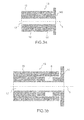
- the compact excitation module 10 represented on the Figures 1 and 2 comprises two RF radiofrequency exciters 11, 12 coupled together in parallel to a longitudinal axis 5 via a rotating joint 13 coupled to a rotary actuator 18.
- the rotary joint consists of two distinct parts 14, 15, respectively fixed 14 and rotary 15, fitted together, without contact, parallel to the longitudinal axis 5, the two fixed and rotatable parts having a cylindrical axial through opening forming a axial cylindrical waveguide 17 common to both fixed and rotary parts 14, 15.
- the two parts, respectively fixed 14 and rotary 15, of the rotary joint 13 respectively form a stator and a rotor rotatable about the longitudinal axis 5.
- the two RF exciters 11, 12 are mounted on either side of the seal rotating 13, respectively on the fixed portion 14 and rotating 15, the rotary joint.
- the first RF exciter 11 mounted on the stator of the rotary joint is thus fixed while the second RF exciter 12 mounted on the rotor of the rotary joint is rotatable about the longitudinal axis 5.
- the compact excitation module shown in FIG. figure 1 further comprises at least one input port connected to a corresponding port of the first RF exciter 11 and at least one output port connected to a corresponding port of the second RF exciter 12.
- the number of input and output ports of the module compact excitation circuit 10 is equal to the number of channels of each RF exciter.
- this number is equal to 1 when each RF exciter used is single-channel, and equal to two when each RF exciter is dual-channel as shown in the example of FIG. figure 1 which has two input ports 24, 25 and two output ports 26, 27. It is also possible to use RF drivers having an input / output number greater than two.
- the two parts, respectively fixed 14 and movable 15, of the rotary joint have geometries of complementary shapes, male and female, and are separated by an intermediate space 16.
- the rotor 15 is the female part and the stator 14 is the male part, but alternatively, it is also possible to have the opposite configuration in which the rotor is the male part and the stator the female part .
- the walls of the male and female parts can be flat and smooth as illustrated on the figure 3a .
- the walls of the male and / or female parts may comprise corrugations which constitute radiofrequency traps, each radio frequency trap being equivalent to an electrical short circuit, which makes it possible to avoid electromagnetic leakage between the two parts of the rotating joint.
- the radiofrequency trap may be constituted by a cavity 8 formed in the wall of the male part 14 and / or the female part 15 of the rotary joint 13, as represented for example on the figure 3b , or by several successive cavities.
- the cylindrical through-hole 17 of the rotary joint 13 forms a circular-section waveguide allowing, for example, the propagation of two electromagnetic waves in circular circular polarization between the two RF exciters 11, 12.
- Each RF exciter comprises a main waveguide mounted along the common longitudinal axis 5 and coupled to the axial cylindrical waveguide 17 of the rotary joint 13.
- the architecture of the RF exciters 11, 12 is of no importance. a functional point of view. It is only necessary that the exciters are made in a waveguide technology and that they are capable of producing one or more RF waves either in the fundamental electromagnetic mode TE11 with circular polarization, or in an electromagnetic mode with symmetry of revolution, such as TM01 mode for example. It is thus possible to use known RF exciters comprising a single RF channel and a single operating frequency band or exciters comprising two RF channels operating in bi-polarization and in a single frequency band.
- each RF exciter may comprise a septum polarizer or an OMT orthomode transducer.
- the figure 4 illustrates an example of a two-way planar compact RF exciter 11 for single-frequency and bipolarization operation and for use in the compact excitation module of the invention.
- the RF exciter 11 comprises a planar RF radiofrequency circuit consisting of a two-branched orthomode transducer OMT 30 and two RF recombination circuits 28, 29 connected to the two input / output ports 24, 25 via a coupler.
- the OMT comprises a main waveguide 23 with a circular section having a longitudinal axis arranged parallel to the axis 5 and comprises two transverse branches located in a plane perpendicular to the axis 5 and respectively coupled to the main waveguide by two axial coupling slots.
- the two axial coupling slots pass through the wall of the axial waveguide and are angularly spaced at an angle equal to 90 °.
- the two transverse branches of the OMT are respectively connected to the two RF recombination circuits 28, 29 of the RF exciter 11 by means of filters.
- the two RF recombination circuits 28, 29 make it possible to produce two right and left circular polarization waves in the main cylindrical waveguide 23 of the OMT.
- the radiofrequency components have a planar structure perpendicular to the axis 5 and are dedicated to the processing of RF radio frequency signals corresponding to the same frequency band.
- the invention is not limited to this type of RF exciter. Any other single-channel or multi-channel exciter can also be used.
- the number of input / output ports of the exciter is directly related to the number of channels of the RF exciter.
- the two RF exciters 11, 12 are mounted on either side of the rotary joint 13, the main waveguides of the two RF exciters 11, 12 being coupled to each other via the axial waveguide 17 of the rotating joint 13.
- the main waveguide of the first compact exciter 11 is fixed to the stator portion of the rotary joint 13 and in the extension of the axial waveguide 17 of the rotary joint
- the main waveguide of the second compact exciter 12 is attached to the rotor portion of the rotary joint 13 and in the extension of the axial waveguide 17 of the rotary joint.
- the main waveguides of the two compact exciters 11, 12 and the axial waveguide 17 of the rotary joint 13 are therefore aligned along the same common longitudinal axis, parallel to the axis 5 and form a common cylindrical waveguide for ensuring the radiofrequency link, that is to say the propagation of the electromagnetic waves, between the input port or ports 24, 25 of the first exciter 11 and the output port or ports 26, 27 corresponding to the second exciter 12.
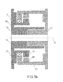
- the compact excitation module further comprises a rotary actuator 18 having a cylindrical axial through opening 40 oriented along the longitudinal axis 5, in which is housed the rotary joint 13, as shown in FIGS. figures 5a and 5b .
- the rotary joint and the rotary actuator are therefore coaxial.
- the rotary actuator 18 comprises a rotor 19 coupled to the rotor 15 of the rotary joint 13 and a stator 20 coupled to the stator 14 of the rotary joint 13.
- the stator may be mounted on a first support part 21 and the rotor 15 may be mounted on a second support part 22.
- the second support part 22 may comprise an end mounted on the first support part 21 via of an interface piece such as for example a ball bearing 3.
- the rotary actuator 18 drives the rotor of the rotary joint 13 in rotation around the longitudinal axis 5 which in turn drives the second exciter 12 integral with the rotor of the rotary joint.
- the first exciter 11 secured to the stator of the rotary joint 13 remains fixed.
- the radiofrequency link between the two exciters 11, 12 is provided by the longitudinal waveguide 17 of axis 5 common to the two compact exciters 11, 12 and the rotary joint 13.
- the compact excitation module 10 thus makes it possible, in a reduced volume, to provide the mechanical motorization and the radiofrequency link between two parts of an antenna respectively fixed and mobile in rotation. It thus makes it possible to ensure the orientation of an element of an antenna, for example a radiating element, by rotation about the axis 5, of the second exciter 12 secured to the rotor 15 of the rotary joint 13. For this purpose, the accesses of the radiating element of the antenna must be respectively connected to the output ports of the second exciter 12 secured to the rotor 15 of the rotary joint.
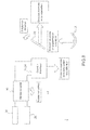
- the figure 6 illustrates a first example of a block diagram of a very compact biaxial mobile antenna architecture, comprising a set of two compact excitation modules 10, 50 coupled to each other and a radiating horn 34 associated with a polarizer 33 coupled to this assembly, according to the invention.
- a compact view and an exploded view of the corresponding antenna are illustrated on the figures 7a and 7b .
- the antenna comprises a first compact module 10 comprising a longitudinal axis oriented along a first azimuth axis of rotation Z and a second compact module 50 having a longitudinal axis oriented along a second axis of rotation in elevation X perpendicular to the first axis Z.
- each compact module 10, 50 is connected perpendicularly to one another, for example by angled waveguides or coaxial cables 35, 36 connected between two outputs of the first compact module 10 and two inputs of the second compact module 50.
- the second compact module 50 is connected at the input of a polarizer 33 at the output of which is connected the radiating horn 34.
- Each compact module 10, 50 comprises two exciters 11, 12 coupled together by a rotating joint 13 housed in an axial opening of a respective rotary actuator 18 as described in connection with the Figures 1 and 2 .
- the first compact module 10 comprises a first rotary actuator which drives the rotor of a first rotary joint and the exciter which is secured to this rotor in a rotational movement about the Z axis.
- the second compact module 50 comprises a second rotary actuator which drives the rotor of a second rotary joint and the exciter which is secured to it in a rotational movement about the axis X.
- the radiating horn 34 associated with the polarizer 33 coupled to the rotating part of the second compact module 50 is thus rotated about the elevation axis X by means of the rotor of the second rotary joint and around the azimuth axis Z via the rotor of the first rotary joint, the angle of rotation in azimuth typically being between -180 ° and 180 °, the elevation angle of rotation being typically between -70 ° and + 70 °.
- the figure 8 illustrates a second example of a block diagram of a very compact biaxial mobile antenna architecture, comprising a compact excitation module 10 coupled by a radiofrequency link to a radiating horn 34 associated with a polarizer 33, a reflector 31 and a plane mirror 32 inclined relative to an axis of elevation X, according to the invention.
- the reflector 31 may be parabolic surface or preformed surface (English, shaped reflector).
- a perspective view and a side view of the corresponding antenna are illustrated on the Figures 9a and 9b .
- the reflector 31 and the plane mirror 32 are mounted on a plate 38 of the mobile antenna rotated about an azimuth axis Z. Alternatively, the reflector and the mirror may be mechanically connected to each other by means of bridges. .
- This antenna architecture comprises only one compact excitation module 10 comprising a longitudinal axis oriented along the azimuth axis Z.
- the compact excitation module 10 housed inside the plate 38 and not visible on Figures 9a and 9b , comprises two exciters coupled together by a rotary joint housed in an axial opening of a respective rotary actuator as described in connection with the Figures 1 and 2 .
- the rotary actuator drives the plate 38 of the antenna and the rotor of the rotary joint as well as the exciter which is secured to this rotor in a rotational movement about the azimuth axis Z.
- the radiating horn associated with the polarizer is coupled to the exciter integral with the rotor of the rotary joint which drives it in rotation around the azimuth axis Z.
- the radiating horn 34 is placed in front of the reflector 31 which ensures the reflection of the radiofrequency wave radiated by the horn 34 towards the plane mirror 32 placed around the radiating horn 34 and oriented towards an elevation direction forming an adjustable elevation angle.
- the plane mirror 32 reflects the radiofrequency wave emitted by the radiating horn assembly 34 and reflector 31 in the desired direction.
- the mechanical azimuth misalignment of the beam emitted by the antenna is achieved by the joint rotation of the plate 38 of the antenna and the rotor of the rotary joint and the elevation misalignment is achieved by modifying the angle of inclination of the antenna. plane mirror 32 with respect to the elevation axis.
- This very compact antenna architecture allows a radiofrequency wave to be transmitted in bipolarization in any chosen direction, in a wide range of angular sweeps corresponding to an angle of rotation in azimuth typically between -180 ° and 180 °, and at an elevation angle ⁇ of rotation typically between -70 ° and + 70 °.
- the invention is not limited to a particular type of RF exciter but can be applied to any type of RF exciter, of mode TM01 or TE01, equipped with a polarizer and / or an OMT, comprising one or more RF channels.
- the input / output number of each exciter is not limited to one or two, but may be greater than two.
Landscapes
- Variable-Direction Aerials And Aerial Arrays (AREA)
- Waveguide Connection Structure (AREA)
Abstract
Description
- La présente invention concerne un module compact d'excitation radiofréquence à cinématique intégrée et une antenne compacte biaxe comportant un tel module compact. Elle s'applique aux antennes à agilité de pointage qui doivent offrir un large domaine de pointage en azimut et en élévation ainsi qu'un fonctionnement en émission, en réception et/ou en bipolarisation. Elle s'applique en particulier dans le domaine spatial, aux antennes montées sur des satellites.
- Pour des satellites en orbite basse, dits défilants, ne disposant que de faibles volumes pour implanter des équipements d'antenne, lorsque la mission exige à la fois une forte agilité de pointage et un fonctionnement de l'antenne en émission et en réception et en bipolarisation, le volume alloué en hauteur pour implanter l'antenne est souvent critique.
- Les solutions d'antennes à agilité de pointage connues ne permettent pas d'assurer à la fois, la cinématique de pointage ainsi qu'un fonctionnement en bipolarisation et un fonctionnement en émission et réception dans un volume contraint.
- Il est notamment connu de réaliser une antenne à réflecteur comportant une source fixe centrée dans laquelle le réflecteur a une symétrie de révolution et comporte un mécanisme de pointage qui l'actionne en rotation selon deux axes azimut et élévation. L'agilité de pointage est obtenue grâce au mouvement du réflecteur. Cependant la symétrie de révolution du réflecteur ne permet pas de maximiser le gain de l'antenne en limite de la couverture ni de maîtriser les performances de polarisation croisée sur un large domaine de balayage. En outre, il est difficile de minimiser la hauteur de l'antenne en raison de la position de la source qui est généralement très éloignée du réflecteur et la longueur du guide d'onde pour atteindre la source est importante. Par ailleurs, cette solution d'antenne ne permet pas un fonctionnement avec des angles d'élévation élevée.
- Il est également connu de réaliser une antenne à double réflecteurs comportant une source placée devant le réflecteur secondaire dans laquelle l'agilité de pointage de l'antenne est obtenue sur un axe d'azimut grâce au mouvement de l'ensemble des deux réflecteurs et de la source. L'agilité de pointage de l'antenne sur un axe d'élévation est obtenue grâce au mouvement de l'ensemble des deux réflecteurs par rapport à la source qui reste fixe. Les inconvénients sont que cette solution d'antenne ne permet pas un fonctionnement en bipolarisation et en outre, le volume nécessaire pour l'implantation de la cinématique de l'antenne est important.
- Il est également connu de réaliser une antenne comportant un réflecteur centré dans laquelle l'agilité de pointage est obtenue par un ensemble de trois actuateurs linéaires associés à des bras articulés. La jonction radiofréquence bipolarisation est assurée par deux câbles coaxiaux. Les inconvénients sont que cette solution présente un encombrement, une masse et un coût importants. En outre, les liaisons radiofréquence réalisées par des câbles coaxiaux souples posent des problèmes de durée de vie.
- Le but de l'invention est de remédier aux inconvénients des antennes à agilité de pointage connues et de réaliser un module compact d'excitation radiofréquence à cinématique intégrée apte à être connecté à un élément rayonnant d'une antenne, permettant d'assurer une agilité de pointage de l'antenne en azimut et en élévation et permettant un fonctionnement dans une ou plusieurs bandes de fréquence et pour une seule ou deux polarisations différentes.
- Pour cela, l'invention concerne un module compact d'excitation radiofréquence comportant deux excitateurs radiofréquence et un joint tournant couplés entre eux selon un axe longitudinal commun, le joint tournant comportant deux parties distinctes, respectivement fixe et rotative autour de l'axe longitudinal commun, les deux excitateurs radiofréquence étant montés de part et d'autre du joint tournant, respectivement sur les parties fixe et rotative, et couplés axialement entre eux par l'intermédiaire du joint tournant. Le module compact comporte en outre un actionneur rotatif pourvu d'une ouverture traversante axiale orientée selon l'axe longitudinal commun, le joint tournant étant logé dans l'ouverture traversante axiale de l'actionneur rotatif.
- Avantageusement, les parties fixe et rotative du joint tournant sont emmanchées entre elles, sans contact, parallèlement à l'axe longitudinal commun, les deux parties fixe et rotative comportant chacune une ouverture axiale cylindrique traversante formant un guide d'onde cylindrique axial.
- Avantageusement, les parties fixe et rotative du joint tournant sont séparées par un espace intermédiaire et, dans l'espace intermédiaire, au moins l'une des parties fixe ou rotative peut comporter des parois munies de corrugations.
- Alternativement, dans l'espace intermédiaire, au moins l'une des parties fixe ou rotative peut comporter des parois munies d'au moins une cavité.
- Avantageusement chaque excitateur radiofréquence comporte un guide d'onde principal monté selon l'axe longitudinal commun et couplé au guide d'onde cylindrique axial du joint tournant.
- Avantageusement, chaque excitateur RF peut comporter un transducteur orthomode OMT couplé au guide d'onde principal de l'excitateur RF.
- Alternativement, chaque excitateur RF peut comporter un polariseur couplé au guide d'onde principal de l'excitateur RF.
- L'invention concerne aussi une antenne compacte biaxe comportant deux modules compacts d'excitation et un cornet rayonnant associé à un polariseur, les axes longitudinaux des deux modules compact étant orientés perpendiculairement entre eux, le deuxième module compact étant relié au polariseur auquel est connecté le cornet rayonnant.
- L'invention concerne enfin une antenne compacte biaxe comportant un seul module compact d'excitation, un cornet rayonnant associé à un polariseur, un réflecteur et un miroir plan placé autour du cornet rayonnant et incliné par rapport à un axe d'élévation, le cornet rayonnant étant placé devant le réflecteur, le module compact d'excitation comportant un axe longitudinal orienté selon un axe d'azimut.
- D'autres particularités et avantages de l'invention apparaîtront clairement dans la suite de la description donnée à titre d'exemple purement illustratif et non limitatif, en référence aux dessins schématiques annexés qui représentent :
-
figure 1 : un schéma synoptique d'un module compact d'excitation à cinématique intégrée, selon l'invention ; -
figure 2 : un schéma éclaté de l'agencement axial du module compact d'excitation à cinématique intégrée, selon l'invention; -
figure 3a : un schéma en coupe axiale d'un premier exemple de réalisation du joint tournant, selon l'invention ; -
figure 3b : un schéma en coupe axiale d'un deuxième exemple de réalisation du joint tournant, selon l'invention ; -
figure 4 : un schéma en coupe transversale, d'un exemple d'excitateur RF apte à être utilisé dans le module compact d'excitation correspondant auxfigures 1 et 2 , selon l'invention ; -
figures 5a et5b : deux schémas en coupe axiale, de deux exemples d'agencements d'un joint tournant dans un orifice axial d'un actionneur rotatif, selon l'invention ; -
figure 6 : un schéma synoptique d'un premier exemple d'architecture d'antenne mobile biaxe très compacte, comportant un ensemble de deux modules compacts d'excitation couplés entre eux et un cornet rayonnant couplé à cet ensemble, selon l'invention ; -
figures 7a et7b : une vue compacte et une vue éclatée de l'antenne correspondant à lafigure 6 , selon l'invention ; -
figure 8 : un schéma synoptique d'un deuxième exemple d'architecture d'antenne mobile biaxe très compacte, comportant un module compact d'excitation couplé à un cornet rayonnant, un réflecteur parabolique et un miroir réflecteur mobile en élévation, selon l'invention ; -
figures 9a et 9b : deux vues en perspective et de profil de l'antenne correspondant à lafigure 8 , selon l'invention. - Selon l'invention, le module compact d'excitation 10 représenté sur les
figures 1 et 2 comporte deux excitateurs radiofréquence RF 11, 12 couplés entre eux parallèlement à un axe longitudinal 5 par l'intermédiaire d'un joint tournant 13 couplé à un actionneur rotatif 18. Comme représenté sur lesfigures 3a et 3b , le joint tournant est constitué de deux parties distinctes 14, 15, respectivement fixe 14 et rotative 15, emmanchées entre elles, sans contact, parallèlement à l'axe longitudinal 5, les deux parties fixe et rotative comportant une ouverture axiale cylindrique traversante formant un guide d'onde cylindrique 17 axial commun aux deux parties fixe et rotative 14, 15 . Les deux parties, respectivement fixe 14 et rotative 15, du joint tournant 13 forment respectivement un stator et un rotor mobile en rotation autour de l'axe longitudinal 5. Les deux excitateurs RF 11, 12 sont montés de part et d'autre du joint tournant 13, respectivement sur les parties fixe 14 et rotative 15, du joint tournant. Le premier excitateur RF 11 monté sur le stator du joint tournant est donc fixe alors que le deuxième excitateur RF 12 monté sur le rotor du joint tournant est mobile en rotation autour de l'axe longitudinal 5. Le module compact d'excitation représenté sur lafigure 1 comporte en outre au moins un port d'entrée relié à un port correspondant du premier excitateur RF 11 et au moins un port de sortie relié à un port correspondant du deuxième excitateur RF 12. Le nombre de ports d'entrée et de sortie du module d'excitation compact 10 est égal au nombre de voies de chaque excitateur RF. Par exemple, ce nombre est égal 1 lorsque chaque excitateur RF utilisé est mono-voie, et égal à deux lorsque chaque excitateur RF est bi-voies comme représenté sur l'exemple de lafigure 1 qui comporte deux ports d'entrée 24, 25 et deux ports de sortie 26, 27. Il est également possible d'utiliser des excitateurs RF comportant un nombre d'entrée/sortie supérieur à deux. - Dans l'exemple de la
figure 3a , les deux parties, respectivement fixe 14 et mobile 15, du joint tournant ont des géométries de formes complémentaires, mâle et femelle, et sont séparées par un espace 16 intermédiaire. Dans l'exemple explicitement représenté, le rotor 15 est la partie femelle et le stator 14 est la partie mâle, mais alternativement, il est également possible d'avoir la configuration inverse dans laquelle le rotor serait la partie mâle et le stator la partie femelle. Dans l'espace 16 intermédiaire séparant les deux parties mâle et femelle du joint tournant 13, les parois des parties mâle et femelle peuvent être planes et lisses comme illustré sur lafigure 3a . Alternativement, dans l'espace 16 intermédiaire, les parois des parties mâle et/ou femelle peuvent comporter des corrugations qui constituent des pièges radiofréquence, chaque piège radiofréquence étant équivalent à un court-circuit électrique, ce qui permet d'éviter les fuites électromagnétiques entre les deux parties du joint tournant. Alternativement, dans l'espace 16 intermédiaire, le piège radiofréquence peut être constitué par une cavité 8 aménagée dans la paroi de la partie mâle 14 et/ou de la partie femelle 15 du joint tournant 13, comme représenté par exemple sur lafigure 3b , ou par plusieurs cavités successives. L'ouverture axiale cylindrique traversante 17 du joint tournant 13 forme un guide d'onde à section circulaire permettant par exemple la propagation de deux ondes électromagnétiques en polarisation circulaire croisée entre les deux excitateurs RF 11, 12. - Chaque excitateur RF comporte un guide d'onde principal monté selon l'axe longitudinal commun 5 et couplé au guide d'onde cylindrique axial 17 du joint tournant 13. L'architecture des excitateurs RF 11, 12 n'a pas d'importance d'un point de vue fonctionnel. Il est juste nécessaire que les excitateurs soient réalisés dans une technologie guide d'onde et qu'ils soient aptes à élaborer une ou plusieurs ondes RF soit dans le mode électromagnétique fondamental TE11 à polarisation circulaire, soit dans un mode électromagnétique à symétrie de révolution, tel que le mode TM01 par exemple. Il est ainsi possible d'utiliser des excitateurs RF connus comportant une seule voie RF et une seule bande de fréquence de fonctionnement ou des excitateurs comportant deux voies RF fonctionnant en bi-polarisation et dans une seule bande de fréquence. De même, de manière connue, pour un fonctionnement dans deux fréquences de fonctionnement différentes ou plus, il est possible d'utiliser un excitateur RF à deux étages ou plus, chaque étage étant dédié à une fréquence particulière, ou de combiner l'excitateur RF avec un polariseur. Dans le cas d'un fonctionnement en bipolarisation, chaque excitateur RF peut comporter un polariseur à septum ou un transducteur orthomode OMT.
- A titre d'exemple non limitatif, la
figure 4 illustre un exemple d'excitateur RF 11 compact planaire à deux voies permettant un fonctionnement mono-fréquence et bipolarisation et pouvant être utilisé dans le module compact d'excitation de l'invention. Dans l'exemple de lafigure 4 , l'excitateur RF 11 comporte une chaîne radiofréquence RF planaire constituée d'un transducteur orthomode OMT à deux branches 30 et de deux circuits de recombinaison RF 28, 29 reliés aux deux ports d'entrée/sortie 24, 25 par l'intermédiaire d'un coupleur. L'OMT comporte un guide d'onde principal 23 à section circulaire ayant un axe longitudinal disposé parallèlement à l'axe 5 et comporte deux branches transversales situées dans un plan perpendiculaire à l'axe 5 et respectivement couplées au guide d'onde principal par deux fentes axiales de couplage. Les deux fentes axiales de couplage traversent la paroi du guide d'onde axial et sont espacées angulairement d'un angle égal à 90°. Les deux branches transversales de l'OMT sont respectivement reliées aux deux circuits de recombinaison RF 28, 29 de l'excitateur RF 11 par l'intermédiaire de filtres. Les deux circuits de recombinaison RF 28, 29 permettent l'élaboration de deux ondes en polarisation circulaire droite et gauche dans le guide d'onde cylindrique principal 23 de l'OMT. Les composants radiofréquence ont une structure planaire perpendiculaire à l'axe 5 et sont dédiés au traitement des signaux radiofréquence RF correspondant à une même bande de fréquence. Bien entendu, l'invention n'est pas limitée à ce type d'excitateur RF. Tout autre excitateur mono-voie ou muti-voies peut également être utilisé. Le nombre de ports d'entrée/sortie de l'excitateur est directement lié au nombre de voies de l'excitateur RF. - Comme illustré sur la
figure 2 , les deux excitateurs RF 11, 12 sont montés de part et d'autre du joint tournant 13, les guides d'onde principaux des deux excitateurs RF 11, 12 étant couplés entre eux par l'intermédiaire du guide d'onde axial 17 du joint tournant 13. Le guide d'onde principal du premier excitateur compact 11 est fixé à la partie stator du joint tournant 13 et dans le prolongement du guide d'onde axial 17 du joint tournant, le guide d'onde principal du second excitateur compact 12 est fixé à la partie rotor du joint tournant 13 et dans le prolongement du guide d'onde axial 17 du joint tournant. Les guides d'onde principaux des deux excitateurs compacts 11, 12 et le guide d'onde axial 17 du joint tournant 13 sont donc alignés selon un même axe longitudinal commun, parallèle à l'axe 5 et forment un guide d'onde cylindrique commun permettant d'assurer la liaison radiofréquence, c'est-à-dire la propagation des ondes électromagnétiques, entre le ou les ports d'entrée 24, 25 du premier excitateur 11 et le ou les ports de sortie 26, 27 correspondants du deuxième excitateur 12. Le module compact d'excitation comporte en outre un actionneur rotatif 18 comportant une ouverture axiale cylindrique traversante 40 orientée selon l'axe longitudinal 5, dans laquelle est logé le joint tournant 13, comme représenté sur lesfigures 5a et5b . Le joint tournant et l'actionneur rotatif sont donc coaxiaux. L'actionneur rotatif 18 comporte un rotor 19 couplé au rotor 15 du joint tournant 13 et un stator 20 couplé au stator 14 du joint tournant 13. Comme représenté sur l'exemple de lafigure 5b , le stator peut être monté sur une première pièce support 21 et le rotor 15 peut être monté sur une deuxième pièce support 22. Dans ce cas, la deuxième pièce support 22 peut comporter une extrémité montée sur la première pièce support 21 par l'intermédiaire d'une pièce d'interface tel que par exemple un roulement à billes 3. En fonctionnement, l'actionneur rotatif 18 entraîne le rotor du joint tournant 13 en rotation autour de l'axe longitudinal 5 qui entraîne à son tour le deuxième excitateur 12 solidaire du rotor du joint tournant. Le premier excitateur 11 solidaire du stator du joint tournant 13 reste fixe. La liaison radiofréquence entre les deux excitateurs 11, 12 est assurée par le guide d'onde longitudinal 17 d'axe 5 commun aux deux excitateurs compacts 11, 12 et au joint tournant 13. - Le module compact d'excitation 10 permet donc, dans un volume réduit, d'assurer la motorisation mécanique et la liaison radiofréquence, entre deux parties d'une antenne respectivement fixe et mobile en rotation. Il permet ainsi d'assurer l'orientation d'un élément d'une antenne, par exemple un élément rayonnant, par rotation, autour de l'axe 5, du deuxième excitateur 12 solidaire du rotor 15 du joint tournant 13. Pour cela, les accès de l'élément rayonnant de l'antenne doivent être respectivement connectés aux accès de sortie du deuxième excitateur 12 solidaire du rotor 15 du joint tournant.
- Il est possible de combiner deux mouvements d'entraînement en rotation selon deux axes différents, par exemple orthogonaux entre eux, et d'obtenir par exemple une rotation d'un axe de pointage d'une antenne en azimut et en élévation, par exemple en combinant deux modules compact d'excitation 10, 50 identiques couplés en série. Le couplage en série des deux modules compact d'excitation 10, 50 peut par exemple être réalisé par l'intermédiaire de câbles coaxiaux ou de guides d'onde coudés comme représenté sur les
figures 6 ,7a ,7b . - La
figure 6 illustre un premier exemple de schéma synoptique d'une architecture d'antenne mobile biaxe très compacte, comportant un ensemble de deux modules compacts d'excitation 10, 50 couplés entre eux et un cornet 34 rayonnant associé à un polariseur 33 couplé à cet ensemble, selon l'invention. Une vue compacte et une vue éclatée de l'antenne correspondante sont illustrées sur lesfigures 7a et7b . L'antenne comporte un premier module compact 10 comportant un axe longitudinal orienté selon un premier axe de rotation en azimut Z et un deuxième module compact 50 ayant un axe longitudinal orienté selon un deuxième axe de rotation en élévation X perpendiculaire au premier axe Z. Les deux modules compacts 10, 50 sont reliés perpendiculairement entre eux, par exemple par des guides d'onde coudés ou des câbles coaxiaux 35, 36 connectés entre deux sorties du premier module compact 10 et deux entrées du deuxième module compact 50. En sortie de l'ensemble des deux modules compacts, le deuxième module compact 50 est relié en entrée d'un polariseur 33 en sortie duquel est connecté le cornet rayonnant 34. Chaque module compact 10, 50 comporte deux excitateurs 11, 12 couplés entre eux par un joint tournant 13 logé dans une ouverture axiale d'un actuateur rotatif 18 respectif comme décrit en liaison avec lesfigures 1 et 2 . Le premier module compact 10 comporte un premier actionneur rotatif qui entraîne le rotor d'un premier joint tournant ainsi que l'excitateur qui est solidaire de ce rotor dans un mouvement de rotation autour de l'axe Z. Le deuxième module compact 50 comporte un deuxième actionneur rotatif qui entraîne le rotor d'un deuxième joint tournant et l'excitateur qui lui est solidaire dans un mouvement de rotation autour de l'axe X. Le cornet rayonnant 34 associé au polariseur 33 couplé à la partie rotative du deuxième module compact 50 est donc entraîné en rotation autour de l'axe d'élévation X par l'intermédiaire du rotor du deuxième joint tournant et autour de l'axe d'azimut Z par l'intermédiaire du rotor du premier joint tournant, l'angle de rotation en azimut étant typiquement compris entre -180° et 180°, l'angle de rotation en élévation étant typiquement compris entre -70° et +70°. Ces deux rotations combinées permettent d'assurer une orientation du cornet rayonnant 34 de l'antenne par rapport à deux axes orthogonaux Z d'azimut et X d'élévation et d'assurer un pointage du faisceau radiofréquence rayonné par l'antenne dans une direction choisie dans un cône de demi-angle au sommet de l'ordre de 70° à 80°. - Alternativement, selon un autre mode de réalisation de l'invention, il est possible de combiner deux mouvements d'entraînement en rotation selon deux axes différents, par exemple orthogonaux entre eux, et d'obtenir par exemple une rotation d'un axe de pointage d'une antenne en azimut et en élévation, en combinant un module compact d'excitation avec un miroir plan incliné comme représenté sur les
figures 8 ,9a, 9b . - La
figure 8 illustre un deuxième exemple d'un schéma synoptique d'une architecture d'antenne mobile biaxe très compacte, comportant un module compact d'excitation 10 couplé par un lien radiofréquence à un cornet rayonnant 34 associé à un polariseur 33, un réflecteur 31 et un miroir plan 32 incliné par rapport à un axe d'élévation X, selon l'invention. Le réflecteur 31 peut être à surface parabolique ou à surface préformée (en anglais, shaped reflector). Une vue en perspective et une vue de profil de l'antenne correspondante sont illustrées sur lesfigures 9a et 9b . Le réflecteur 31 et le miroir plan 32 sont montés sur une platine 38 de l'antenne mobile en rotation autour d'un axe d'azimut Z. Alternativement, le réflecteur et le miroir pourront être reliés mécaniquement entre eux par l'intermédiaire de bracons. Cette architecture d'antenne ne comporte qu'un seul module compact d'excitation 10 comportant un axe longitudinal orienté selon l'axe d'azimut Z. Le module compact d'excitation 10, logé à l'intérieur de la platine 38 et non visible sur lesfigures 9a et 9b , comporte deux excitateurs couplés entre eux par un joint tournant logé dans une ouverture axiale d'un actionneur rotatif respectif comme décrit en liaison avec lesfigures 1 et 2 . L'actionneur rotatif entraîne la platine 38 de l'antenne et le rotor du joint tournant ainsi que l'excitateur qui est solidaire de ce rotor dans un mouvement de rotation autour de l'axe d'azimut Z. Le cornet rayonnant associé au polariseur est couplé à l'excitateur solidaire du rotor du joint tournant qui l'entraîne en rotation autour de l'axe d'azimut Z. Le cornet rayonnant 34 est placé devant le réflecteur 31 qui assure la réflexion de l'onde radiofréquence rayonnée par le cornet 34 en direction du miroir plan 32 placé autour du cornet rayonnant 34 et orienté vers une direction d'élévation formant un angle d'élévation réglable. Le miroir plan 32 réfléchit l'onde radiofréquence émise par l'ensemble cornet rayonnant 34 et réflecteur 31 dans la direction souhaitée. - Le dépointage mécanique en azimut du faisceau émis par l'antenne est réalisé par la rotation conjointe de la platine 38 de l'antenne et du rotor du joint tournant et le dépointage en élévation est réalisé par la modification de l'angle d'inclinaison du miroir plan 32 par rapport à l'axe d'élévation. Cette architecture d'antenne très compacte permet une émission d'une onde radiofréquence en bipolarisation dans n'importe quelle direction choisie, dans un large domaine de balayage angulaire correspondant à un angle de rotation en azimut typiquement compris entre -180° et 180°, et à un angle θ de rotation en élévation typiquement compris entre -70° et +70°.
- Bien que l'invention ait été décrite en liaison avec des modes de réalisation particuliers, il est bien évident qu'elle n'y est nullement limitée et qu'elle comprend tous les équivalents techniques des moyens décrits ainsi que leurs combinaisons si celles-ci entrent dans le cadre de l'invention. Ainsi, l'invention n'est pas limitée à un type d'excitateur RF particulier mais peut être appliquée à tout type d'excitateur RF, de mode TM01 ou TE01, équipé d'un polariseur et/ou d'un OMT, comportant une ou plusieurs voies RF. De même, le nombre d'entrée/sortie de chaque excitateur n'est pas limité à un ou deux, mais peut être supérieur à deux.
Claims (9)
- Module compact d'excitation radiofréquence, caractérisé en ce qu'il comporte deux excitateurs radiofréquence RF (11, 12) et un joint tournant (13) couplés entre eux selon un axe longitudinal commun (5), le joint tournant comportant deux parties distinctes, respectivement fixe (14) et rotative (15) autour de l'axe longitudinal commun (5), les deux excitateurs radiofréquence étant montés de part et d'autre du joint tournant, respectivement sur les parties fixe et rotative, et couplés axialement entre eux par l'intermédiaire du joint tournant, et en ce qu'il comporte en outre un actionneur rotatif (18) pourvu d'une ouverture traversante axiale (40) orientée selon l'axe longitudinal commun (5), le joint tournant (13) étant logé dans l'ouverture traversante axiale (40) de l'actionneur rotatif.
- Module compact d'excitation selon la revendication 1, caractérisé en ce que les parties fixe et rotative (14, 15) du joint tournant (13), sont emmanchées entre elles, sans contact, parallèlement à l'axe longitudinal commun (5), les deux parties fixe et rotative comportant chacune une ouverture axiale cylindrique traversante (17) formant un guide d'onde cylindrique axial.
- Module compact d'excitation selon la revendication 2, caractérisé en ce que les parties fixe et rotative du joint tournant sont séparées par un espace (16) intermédiaire et en ce que, dans l'espace intermédiaire, au moins l'une des parties fixe ou rotative comporte des parois munies de corrugations (16).
- Module compact d'excitation selon la revendication 2, caractérisé en ce les parties fixe et rotative du joint tournant sont séparées par un espace (16) intermédiaire et en ce que, dans l'espace intermédiaire, au moins l'une des parties fixe ou rotative comporte des parois munies d'au moins une cavité (8).
- Module compact d'excitation selon l'une des revendications 1 à 4, caractérisé en ce que chaque excitateur RF (11, 12) comporte un guide d'onde principal (23) monté selon l'axe longitudinal commun et couplé au guide d'onde cylindrique axial du joint tournant.
- Module compact d'excitation selon la revendication 5, caractérisé en ce que chaque excitateur RF (11, 12) comporte un transducteur orthomode OMT (30) couplé au guide d'onde principal (23) de l'excitateur RF.
- Module compact d'excitation selon la revendication 5, caractérisé en ce que chaque excitateur RF comporte un polariseur (33) couplé au guide d'onde principal (23) de l'excitateur RF.
- Antenne compacte biaxe caractérisée en ce qu'elle comporte deux modules compacts d'excitation (10, 50) selon l'une des revendications précédentes et un cornet rayonnant (34) associé à un polariseur (33), les axes longitudinaux des deux modules compact étant orientés perpendiculairement entre eux, le deuxième module compact étant relié au polariseur auquel est connecté le cornet rayonnant.
- Antenne compacte biaxe caractérisée en ce qu'elle comporte un seul module compact d'excitation (10) selon l'une des revendications 1 à 7, un cornet rayonnant (34) associé à un polariseur (33), un réflecteur (31) et un miroir plan (32) placé autour du cornet rayonnant et incliné par rapport à un axe d'élévation, le cornet rayonnant étant placé devant le réflecteur, le module compact d'excitation (10) comportant un axe longitudinal orienté selon un axe d'azimut.
Applications Claiming Priority (1)
| Application Number | Priority Date | Filing Date | Title |
|---|---|---|---|
| FR1402674A FR3029018B1 (fr) | 2014-11-26 | 2014-11-26 | Module compact d'excitation radiofrequence a cinematique integree et antenne compacte biaxe comportantau moins un tel module compact |
Publications (1)
| Publication Number | Publication Date |
|---|---|
| EP3026754A1 true EP3026754A1 (fr) | 2016-06-01 |
Family
ID=53008557
Family Applications (1)
| Application Number | Title | Priority Date | Filing Date |
|---|---|---|---|
| EP15195396.5A Withdrawn EP3026754A1 (fr) | 2014-11-26 | 2015-11-19 | Module compact d'excitation radiofréquence à cinématique intégrée et antenne compacte biaxe comportant au moins un tel module compact |
Country Status (4)
| Country | Link |
|---|---|
| US (1) | US9768482B2 (fr) |
| EP (1) | EP3026754A1 (fr) |
| CA (1) | CA2913372C (fr) |
| FR (1) | FR3029018B1 (fr) |
Families Citing this family (5)
| Publication number | Priority date | Publication date | Assignee | Title |
|---|---|---|---|---|
| TWI621776B (zh) * | 2016-01-15 | 2018-04-21 | Wen-San Chou | 空壓機之汽缸出氣構造改良 |
| FR3071363B1 (fr) | 2017-09-19 | 2019-09-06 | Thales | Joint tournant pour une antenne rotative et antenne rotative comportant un tel joint |
| FR3071365B1 (fr) | 2017-09-19 | 2019-09-06 | Thales | Antenne biaxe comportant une premiere partie fixe, une deuxieme partie rotative et un joint tournant |
| FR3090216B1 (fr) | 2018-12-18 | 2020-12-18 | Thales Sa | Joint tournant radiofrequence rf pour dispositif rotatif de guidage d’ondes rf et dispositif rotatif rf incluant un tel joint |
| EP4399934A1 (fr) * | 2021-09-06 | 2024-07-17 | Telefonaktiebolaget LM Ericsson (publ) | Transmission de données à un dispositif de communication sans fil |
Citations (7)
| Publication number | Priority date | Publication date | Assignee | Title |
|---|---|---|---|---|
| US3001159A (en) * | 1957-12-26 | 1961-09-19 | Bell Telephone Labor Inc | Step twist waveguide rotary joint |
| US3715688A (en) * | 1970-09-04 | 1973-02-06 | Rca Corp | Tm01 mode exciter and a multimode exciter using same |
| US4185287A (en) * | 1977-07-25 | 1980-01-22 | Texas Instruments Incorporated | Mechanically scanned antenna system |
| US20070013457A1 (en) * | 2005-07-14 | 2007-01-18 | X-Ether, Inc. | Mode transducer structure |
| US20100149058A1 (en) * | 2008-12-16 | 2010-06-17 | Thales | Compact Excitation Assembly for Generating a Circular Polarization in an Antenna and Method of Fashioning Such a Compact Excitation Assembly |
| WO2013150994A1 (fr) * | 2012-04-02 | 2013-10-10 | 古野電気株式会社 | Dispositif d'antenne |
| US20140104125A1 (en) * | 2011-10-17 | 2014-04-17 | Eric CHOINIERE | Wide scan steerable antenna with no key-hole |
Family Cites Families (1)
| Publication number | Priority date | Publication date | Assignee | Title |
|---|---|---|---|---|
| US20120154239A1 (en) * | 2010-12-15 | 2012-06-21 | Bridgewave Communications, Inc. | Millimeter wave radio assembly with a compact antenna |
-
2014
- 2014-11-26 FR FR1402674A patent/FR3029018B1/fr active Active
-
2015
- 2015-11-19 EP EP15195396.5A patent/EP3026754A1/fr not_active Withdrawn
- 2015-11-23 US US14/949,548 patent/US9768482B2/en active Active
- 2015-11-23 CA CA2913372A patent/CA2913372C/fr active Active
Patent Citations (8)
| Publication number | Priority date | Publication date | Assignee | Title |
|---|---|---|---|---|
| US3001159A (en) * | 1957-12-26 | 1961-09-19 | Bell Telephone Labor Inc | Step twist waveguide rotary joint |
| US3715688A (en) * | 1970-09-04 | 1973-02-06 | Rca Corp | Tm01 mode exciter and a multimode exciter using same |
| US4185287A (en) * | 1977-07-25 | 1980-01-22 | Texas Instruments Incorporated | Mechanically scanned antenna system |
| US20070013457A1 (en) * | 2005-07-14 | 2007-01-18 | X-Ether, Inc. | Mode transducer structure |
| US20100149058A1 (en) * | 2008-12-16 | 2010-06-17 | Thales | Compact Excitation Assembly for Generating a Circular Polarization in an Antenna and Method of Fashioning Such a Compact Excitation Assembly |
| US20140104125A1 (en) * | 2011-10-17 | 2014-04-17 | Eric CHOINIERE | Wide scan steerable antenna with no key-hole |
| WO2013150994A1 (fr) * | 2012-04-02 | 2013-10-10 | 古野電気株式会社 | Dispositif d'antenne |
| US20150054703A1 (en) * | 2012-04-02 | 2015-02-26 | Furuno Electric Co., Ltd. | Antenna device |
Also Published As
| Publication number | Publication date |
|---|---|
| FR3029018A1 (fr) | 2016-05-27 |
| US9768482B2 (en) | 2017-09-19 |
| CA2913372C (fr) | 2023-08-08 |
| FR3029018B1 (fr) | 2016-12-30 |
| CA2913372A1 (fr) | 2016-05-26 |
| US20160149280A1 (en) | 2016-05-26 |
Similar Documents
| Publication | Publication Date | Title |
|---|---|---|
| EP3026754A1 (fr) | Module compact d'excitation radiofréquence à cinématique intégrée et antenne compacte biaxe comportant au moins un tel module compact | |
| EP3179551B1 (fr) | Ensemble d'excitation compact bipolarisation pour un element rayonnant d'antenne et reseau compact comportant au moins quatre ensembles d'excitation compacts | |
| EP3726642B1 (fr) | Ecran polariseur a cellule(s) polarisante(s) radiofrequence(s) large bande | |
| EP3086409B1 (fr) | Module structural d'antenne integrant des sources rayonnantes elementaires a orientation individuelle, panneau rayonnant, reseau rayonnant et antenne multifaisceaux comportant au moins un tel module | |
| EP2869400A1 (fr) | Répartiteur de puissance compact bipolarisation, réseau de plusieurs répartiteurs, élément rayonnant compact et antenne plane comportant un tel répartiteur | |
| EP3176875A1 (fr) | Architecture d'antenne active a formation de faisceaux hybride reconfigurable | |
| FR3069713B1 (fr) | Antenne integrant des lentilles a retard a l'interieur d'un repartiteur a base de diviseurs a guide d'ondes a plaques paralleles | |
| WO2010149619A1 (fr) | Systeme d'antenne avec positionneur equilibre | |
| EP3340369B1 (fr) | Architecture de bloc sources déployable, antenne compacte et satellite comportant une telle architecture | |
| EP3155690B1 (fr) | Antenne plate de telecommunication par satellite | |
| EP3249823B1 (fr) | Excitateur radiofréquence compact bi-polarisation et multi-fréquences pour source primaire d'antenne et une source primaire d'antenne equipée d'un tel excitateur radiofréquence | |
| EP4523291A1 (fr) | Antenne faible profil à balayage electronique bidimensionnel | |
| FR3082362A1 (fr) | Systeme de depointage a formation de faisceau | |
| EP3220181A1 (fr) | Systeme optique hybride a encombrement reduit pour antenne reseau imageur | |
| EP3365943B1 (fr) | Dispositif d'antenne d'aide a l'acquisition et systeme d'antenne pour le suivi d'une cible en mouvement associe | |
| EP3155689B1 (fr) | Antenne plate de telecommunication par satellite | |
| EP3035445B1 (fr) | Coupleur de jonction a mode orthogonal et separateur de polarisations et de frequences associe | |
| EP3506426B1 (fr) | Dispositif de pointage de faisceau pour systeme antennaire, systeme antennaire et plateforme associes | |
| EP3157094A1 (fr) | Antenne compacte à ouverture de faisceau modulable | |
| EP4207493A1 (fr) | Antenne rf directive passive à balayage en une ou deux dimensions | |
| EP3075031B1 (fr) | Agencement de structures antennaires pour télécommunications par satellites | |
| FR2929762A1 (fr) | Coupleur mobile pour antenne a lentille de luneberg et antenne a lentille de luneberg associee |
Legal Events
| Date | Code | Title | Description |
|---|---|---|---|
| PUAI | Public reference made under article 153(3) epc to a published international application that has entered the european phase |
Free format text: ORIGINAL CODE: 0009012 |
|
| AK | Designated contracting states |
Kind code of ref document: A1 Designated state(s): AL AT BE BG CH CY CZ DE DK EE ES FI FR GB GR HR HU IE IS IT LI LT LU LV MC MK MT NL NO PL PT RO RS SE SI SK SM TR |
|
| AX | Request for extension of the european patent |
Extension state: BA ME |
|
| 17P | Request for examination filed |
Effective date: 20161019 |
|
| RBV | Designated contracting states (corrected) |
Designated state(s): AL AT BE BG CH CY CZ DE DK EE ES FI FR GB GR HR HU IE IS IT LI LT LU LV MC MK MT NL NO PL PT RO RS SE SI SK SM TR |
|
| 17Q | First examination report despatched |
Effective date: 20181212 |
|
| STAA | Information on the status of an ep patent application or granted ep patent |
Free format text: STATUS: THE APPLICATION HAS BEEN WITHDRAWN |
|
| 18W | Application withdrawn |
Effective date: 20200123 |