EP3026384A2 - Heat exchanger - Google Patents
Heat exchanger Download PDFInfo
- Publication number
- EP3026384A2 EP3026384A2 EP15189507.5A EP15189507A EP3026384A2 EP 3026384 A2 EP3026384 A2 EP 3026384A2 EP 15189507 A EP15189507 A EP 15189507A EP 3026384 A2 EP3026384 A2 EP 3026384A2
- Authority
- EP
- European Patent Office
- Prior art keywords
- tubular element
- heat exchanger
- fins
- annular passage
- outlet
- Prior art date
- Legal status (The legal status is an assumption and is not a legal conclusion. Google has not performed a legal analysis and makes no representation as to the accuracy of the status listed.)
- Granted
Links
Images


Classifications
-
- F—MECHANICAL ENGINEERING; LIGHTING; HEATING; WEAPONS; BLASTING
- F02—COMBUSTION ENGINES; HOT-GAS OR COMBUSTION-PRODUCT ENGINE PLANTS
- F02C—GAS-TURBINE PLANTS; AIR INTAKES FOR JET-PROPULSION PLANTS; CONTROLLING FUEL SUPPLY IN AIR-BREATHING JET-PROPULSION PLANTS
- F02C7/00—Features, components parts, details or accessories, not provided for in, or of interest apart form groups F02C1/00 - F02C6/00; Air intakes for jet-propulsion plants
- F02C7/12—Cooling of plants
- F02C7/16—Cooling of plants characterised by cooling medium
- F02C7/18—Cooling of plants characterised by cooling medium the medium being gaseous, e.g. air
- F02C7/185—Cooling means for reducing the temperature of the cooling air or gas
-
- B—PERFORMING OPERATIONS; TRANSPORTING
- B64—AIRCRAFT; AVIATION; COSMONAUTICS
- B64D—EQUIPMENT FOR FITTING IN OR TO AIRCRAFT; FLIGHT SUITS; PARACHUTES; ARRANGEMENT OR MOUNTING OF POWER PLANTS OR PROPULSION TRANSMISSIONS IN AIRCRAFT
- B64D33/00—Arrangement in aircraft of power plant parts or auxiliaries not otherwise provided for
- B64D33/08—Arrangement in aircraft of power plant parts or auxiliaries not otherwise provided for of power plant cooling systems
-
- B—PERFORMING OPERATIONS; TRANSPORTING
- B64—AIRCRAFT; AVIATION; COSMONAUTICS
- B64D—EQUIPMENT FOR FITTING IN OR TO AIRCRAFT; FLIGHT SUITS; PARACHUTES; ARRANGEMENT OR MOUNTING OF POWER PLANTS OR PROPULSION TRANSMISSIONS IN AIRCRAFT
- B64D33/00—Arrangement in aircraft of power plant parts or auxiliaries not otherwise provided for
- B64D33/08—Arrangement in aircraft of power plant parts or auxiliaries not otherwise provided for of power plant cooling systems
- B64D33/10—Radiator arrangement
-
- F—MECHANICAL ENGINEERING; LIGHTING; HEATING; WEAPONS; BLASTING
- F02—COMBUSTION ENGINES; HOT-GAS OR COMBUSTION-PRODUCT ENGINE PLANTS
- F02C—GAS-TURBINE PLANTS; AIR INTAKES FOR JET-PROPULSION PLANTS; CONTROLLING FUEL SUPPLY IN AIR-BREATHING JET-PROPULSION PLANTS
- F02C3/00—Gas-turbine plants characterised by the use of combustion products as the working fluid
- F02C3/04—Gas-turbine plants characterised by the use of combustion products as the working fluid having a turbine driving a compressor
- F02C3/10—Gas-turbine plants characterised by the use of combustion products as the working fluid having a turbine driving a compressor with another turbine driving an output shaft but not driving the compressor
-
- F—MECHANICAL ENGINEERING; LIGHTING; HEATING; WEAPONS; BLASTING
- F02—COMBUSTION ENGINES; HOT-GAS OR COMBUSTION-PRODUCT ENGINE PLANTS
- F02C—GAS-TURBINE PLANTS; AIR INTAKES FOR JET-PROPULSION PLANTS; CONTROLLING FUEL SUPPLY IN AIR-BREATHING JET-PROPULSION PLANTS
- F02C7/00—Features, components parts, details or accessories, not provided for in, or of interest apart form groups F02C1/00 - F02C6/00; Air intakes for jet-propulsion plants
- F02C7/12—Cooling of plants
- F02C7/14—Cooling of plants of fluids in the plant, e.g. lubricant or fuel
-
- F—MECHANICAL ENGINEERING; LIGHTING; HEATING; WEAPONS; BLASTING
- F02—COMBUSTION ENGINES; HOT-GAS OR COMBUSTION-PRODUCT ENGINE PLANTS
- F02C—GAS-TURBINE PLANTS; AIR INTAKES FOR JET-PROPULSION PLANTS; CONTROLLING FUEL SUPPLY IN AIR-BREATHING JET-PROPULSION PLANTS
- F02C7/00—Features, components parts, details or accessories, not provided for in, or of interest apart form groups F02C1/00 - F02C6/00; Air intakes for jet-propulsion plants
- F02C7/22—Fuel supply systems
- F02C7/224—Heating fuel before feeding to the burner
-
- F—MECHANICAL ENGINEERING; LIGHTING; HEATING; WEAPONS; BLASTING
- F02—COMBUSTION ENGINES; HOT-GAS OR COMBUSTION-PRODUCT ENGINE PLANTS
- F02C—GAS-TURBINE PLANTS; AIR INTAKES FOR JET-PROPULSION PLANTS; CONTROLLING FUEL SUPPLY IN AIR-BREATHING JET-PROPULSION PLANTS
- F02C9/00—Controlling gas-turbine plants; Controlling fuel supply in air- breathing jet-propulsion plants
- F02C9/16—Control of working fluid flow
- F02C9/18—Control of working fluid flow by bleeding, bypassing or acting on variable working fluid interconnections between turbines or compressors or their stages
-
- F—MECHANICAL ENGINEERING; LIGHTING; HEATING; WEAPONS; BLASTING
- F28—HEAT EXCHANGE IN GENERAL
- F28D—HEAT-EXCHANGE APPARATUS, NOT PROVIDED FOR IN ANOTHER SUBCLASS, IN WHICH THE HEAT-EXCHANGE MEDIA DO NOT COME INTO DIRECT CONTACT
- F28D7/00—Heat-exchange apparatus having stationary tubular conduit assemblies for both heat-exchange media, the media being in contact with different sides of a conduit wall
- F28D7/02—Heat-exchange apparatus having stationary tubular conduit assemblies for both heat-exchange media, the media being in contact with different sides of a conduit wall the conduits being helically coiled
-
- F—MECHANICAL ENGINEERING; LIGHTING; HEATING; WEAPONS; BLASTING
- F28—HEAT EXCHANGE IN GENERAL
- F28D—HEAT-EXCHANGE APPARATUS, NOT PROVIDED FOR IN ANOTHER SUBCLASS, IN WHICH THE HEAT-EXCHANGE MEDIA DO NOT COME INTO DIRECT CONTACT
- F28D7/00—Heat-exchange apparatus having stationary tubular conduit assemblies for both heat-exchange media, the media being in contact with different sides of a conduit wall
- F28D7/02—Heat-exchange apparatus having stationary tubular conduit assemblies for both heat-exchange media, the media being in contact with different sides of a conduit wall the conduits being helically coiled
- F28D7/024—Heat-exchange apparatus having stationary tubular conduit assemblies for both heat-exchange media, the media being in contact with different sides of a conduit wall the conduits being helically coiled the conduits of only one medium being helically coiled tubes, the coils having a cylindrical configuration
-
- F—MECHANICAL ENGINEERING; LIGHTING; HEATING; WEAPONS; BLASTING
- F28—HEAT EXCHANGE IN GENERAL
- F28D—HEAT-EXCHANGE APPARATUS, NOT PROVIDED FOR IN ANOTHER SUBCLASS, IN WHICH THE HEAT-EXCHANGE MEDIA DO NOT COME INTO DIRECT CONTACT
- F28D7/00—Heat-exchange apparatus having stationary tubular conduit assemblies for both heat-exchange media, the media being in contact with different sides of a conduit wall
- F28D7/04—Heat-exchange apparatus having stationary tubular conduit assemblies for both heat-exchange media, the media being in contact with different sides of a conduit wall the conduits being spirally coiled
-
- F—MECHANICAL ENGINEERING; LIGHTING; HEATING; WEAPONS; BLASTING
- F28—HEAT EXCHANGE IN GENERAL
- F28D—HEAT-EXCHANGE APPARATUS, NOT PROVIDED FOR IN ANOTHER SUBCLASS, IN WHICH THE HEAT-EXCHANGE MEDIA DO NOT COME INTO DIRECT CONTACT
- F28D7/00—Heat-exchange apparatus having stationary tubular conduit assemblies for both heat-exchange media, the media being in contact with different sides of a conduit wall
- F28D7/08—Heat-exchange apparatus having stationary tubular conduit assemblies for both heat-exchange media, the media being in contact with different sides of a conduit wall the conduits being otherwise bent, e.g. in a serpentine or zig-zag
-
- F—MECHANICAL ENGINEERING; LIGHTING; HEATING; WEAPONS; BLASTING
- F28—HEAT EXCHANGE IN GENERAL
- F28D—HEAT-EXCHANGE APPARATUS, NOT PROVIDED FOR IN ANOTHER SUBCLASS, IN WHICH THE HEAT-EXCHANGE MEDIA DO NOT COME INTO DIRECT CONTACT
- F28D7/00—Heat-exchange apparatus having stationary tubular conduit assemblies for both heat-exchange media, the media being in contact with different sides of a conduit wall
- F28D7/08—Heat-exchange apparatus having stationary tubular conduit assemblies for both heat-exchange media, the media being in contact with different sides of a conduit wall the conduits being otherwise bent, e.g. in a serpentine or zig-zag
- F28D7/082—Heat-exchange apparatus having stationary tubular conduit assemblies for both heat-exchange media, the media being in contact with different sides of a conduit wall the conduits being otherwise bent, e.g. in a serpentine or zig-zag with serpentine or zig-zag configuration
-
- F—MECHANICAL ENGINEERING; LIGHTING; HEATING; WEAPONS; BLASTING
- F28—HEAT EXCHANGE IN GENERAL
- F28D—HEAT-EXCHANGE APPARATUS, NOT PROVIDED FOR IN ANOTHER SUBCLASS, IN WHICH THE HEAT-EXCHANGE MEDIA DO NOT COME INTO DIRECT CONTACT
- F28D7/00—Heat-exchange apparatus having stationary tubular conduit assemblies for both heat-exchange media, the media being in contact with different sides of a conduit wall
- F28D7/08—Heat-exchange apparatus having stationary tubular conduit assemblies for both heat-exchange media, the media being in contact with different sides of a conduit wall the conduits being otherwise bent, e.g. in a serpentine or zig-zag
- F28D7/082—Heat-exchange apparatus having stationary tubular conduit assemblies for both heat-exchange media, the media being in contact with different sides of a conduit wall the conduits being otherwise bent, e.g. in a serpentine or zig-zag with serpentine or zig-zag configuration
- F28D7/085—Heat-exchange apparatus having stationary tubular conduit assemblies for both heat-exchange media, the media being in contact with different sides of a conduit wall the conduits being otherwise bent, e.g. in a serpentine or zig-zag with serpentine or zig-zag configuration in the form of parallel conduits coupled by bent portions
-
- F—MECHANICAL ENGINEERING; LIGHTING; HEATING; WEAPONS; BLASTING
- F28—HEAT EXCHANGE IN GENERAL
- F28D—HEAT-EXCHANGE APPARATUS, NOT PROVIDED FOR IN ANOTHER SUBCLASS, IN WHICH THE HEAT-EXCHANGE MEDIA DO NOT COME INTO DIRECT CONTACT
- F28D7/00—Heat-exchange apparatus having stationary tubular conduit assemblies for both heat-exchange media, the media being in contact with different sides of a conduit wall
- F28D7/10—Heat-exchange apparatus having stationary tubular conduit assemblies for both heat-exchange media, the media being in contact with different sides of a conduit wall the conduits being arranged one within the other, e.g. concentrically
-
- F—MECHANICAL ENGINEERING; LIGHTING; HEATING; WEAPONS; BLASTING
- F28—HEAT EXCHANGE IN GENERAL
- F28D—HEAT-EXCHANGE APPARATUS, NOT PROVIDED FOR IN ANOTHER SUBCLASS, IN WHICH THE HEAT-EXCHANGE MEDIA DO NOT COME INTO DIRECT CONTACT
- F28D7/00—Heat-exchange apparatus having stationary tubular conduit assemblies for both heat-exchange media, the media being in contact with different sides of a conduit wall
- F28D7/10—Heat-exchange apparatus having stationary tubular conduit assemblies for both heat-exchange media, the media being in contact with different sides of a conduit wall the conduits being arranged one within the other, e.g. concentrically
- F28D7/103—Heat-exchange apparatus having stationary tubular conduit assemblies for both heat-exchange media, the media being in contact with different sides of a conduit wall the conduits being arranged one within the other, e.g. concentrically consisting of more than two coaxial conduits or modules of more than two coaxial conduits
-
- F—MECHANICAL ENGINEERING; LIGHTING; HEATING; WEAPONS; BLASTING
- F28—HEAT EXCHANGE IN GENERAL
- F28D—HEAT-EXCHANGE APPARATUS, NOT PROVIDED FOR IN ANOTHER SUBCLASS, IN WHICH THE HEAT-EXCHANGE MEDIA DO NOT COME INTO DIRECT CONTACT
- F28D7/00—Heat-exchange apparatus having stationary tubular conduit assemblies for both heat-exchange media, the media being in contact with different sides of a conduit wall
- F28D7/10—Heat-exchange apparatus having stationary tubular conduit assemblies for both heat-exchange media, the media being in contact with different sides of a conduit wall the conduits being arranged one within the other, e.g. concentrically
- F28D7/106—Heat-exchange apparatus having stationary tubular conduit assemblies for both heat-exchange media, the media being in contact with different sides of a conduit wall the conduits being arranged one within the other, e.g. concentrically consisting of two coaxial conduits or modules of two coaxial conduits
-
- F—MECHANICAL ENGINEERING; LIGHTING; HEATING; WEAPONS; BLASTING
- F28—HEAT EXCHANGE IN GENERAL
- F28D—HEAT-EXCHANGE APPARATUS, NOT PROVIDED FOR IN ANOTHER SUBCLASS, IN WHICH THE HEAT-EXCHANGE MEDIA DO NOT COME INTO DIRECT CONTACT
- F28D7/00—Heat-exchange apparatus having stationary tubular conduit assemblies for both heat-exchange media, the media being in contact with different sides of a conduit wall
- F28D7/16—Heat-exchange apparatus having stationary tubular conduit assemblies for both heat-exchange media, the media being in contact with different sides of a conduit wall the conduits being arranged in parallel spaced relation
- F28D7/1607—Heat-exchange apparatus having stationary tubular conduit assemblies for both heat-exchange media, the media being in contact with different sides of a conduit wall the conduits being arranged in parallel spaced relation with particular pattern of flow of the heat exchange media, e.g. change of flow direction
-
- F—MECHANICAL ENGINEERING; LIGHTING; HEATING; WEAPONS; BLASTING
- F28—HEAT EXCHANGE IN GENERAL
- F28F—DETAILS OF HEAT-EXCHANGE AND HEAT-TRANSFER APPARATUS, OF GENERAL APPLICATION
- F28F1/00—Tubular elements; Assemblies of tubular elements
- F28F1/10—Tubular elements and assemblies thereof with means for increasing heat-transfer area, e.g. with fins, with projections, with recesses
- F28F1/105—Tubular elements and assemblies thereof with means for increasing heat-transfer area, e.g. with fins, with projections, with recesses the means being corrugated elements extending around the tubular elements
-
- F—MECHANICAL ENGINEERING; LIGHTING; HEATING; WEAPONS; BLASTING
- F28—HEAT EXCHANGE IN GENERAL
- F28F—DETAILS OF HEAT-EXCHANGE AND HEAT-TRANSFER APPARATUS, OF GENERAL APPLICATION
- F28F1/00—Tubular elements; Assemblies of tubular elements
- F28F1/10—Tubular elements and assemblies thereof with means for increasing heat-transfer area, e.g. with fins, with projections, with recesses
- F28F1/12—Tubular elements and assemblies thereof with means for increasing heat-transfer area, e.g. with fins, with projections, with recesses the means being only outside the tubular element
- F28F1/14—Tubular elements and assemblies thereof with means for increasing heat-transfer area, e.g. with fins, with projections, with recesses the means being only outside the tubular element and extending longitudinally
-
- F—MECHANICAL ENGINEERING; LIGHTING; HEATING; WEAPONS; BLASTING
- F28—HEAT EXCHANGE IN GENERAL
- F28F—DETAILS OF HEAT-EXCHANGE AND HEAT-TRANSFER APPARATUS, OF GENERAL APPLICATION
- F28F1/00—Tubular elements; Assemblies of tubular elements
- F28F1/10—Tubular elements and assemblies thereof with means for increasing heat-transfer area, e.g. with fins, with projections, with recesses
- F28F1/12—Tubular elements and assemblies thereof with means for increasing heat-transfer area, e.g. with fins, with projections, with recesses the means being only outside the tubular element
- F28F1/14—Tubular elements and assemblies thereof with means for increasing heat-transfer area, e.g. with fins, with projections, with recesses the means being only outside the tubular element and extending longitudinally
- F28F1/16—Tubular elements and assemblies thereof with means for increasing heat-transfer area, e.g. with fins, with projections, with recesses the means being only outside the tubular element and extending longitudinally the means being integral with the element, e.g. formed by extrusion
-
- F—MECHANICAL ENGINEERING; LIGHTING; HEATING; WEAPONS; BLASTING
- F28—HEAT EXCHANGE IN GENERAL
- F28F—DETAILS OF HEAT-EXCHANGE AND HEAT-TRANSFER APPARATUS, OF GENERAL APPLICATION
- F28F1/00—Tubular elements; Assemblies of tubular elements
- F28F1/10—Tubular elements and assemblies thereof with means for increasing heat-transfer area, e.g. with fins, with projections, with recesses
- F28F1/12—Tubular elements and assemblies thereof with means for increasing heat-transfer area, e.g. with fins, with projections, with recesses the means being only outside the tubular element
- F28F1/34—Tubular elements and assemblies thereof with means for increasing heat-transfer area, e.g. with fins, with projections, with recesses the means being only outside the tubular element and extending obliquely
-
- F—MECHANICAL ENGINEERING; LIGHTING; HEATING; WEAPONS; BLASTING
- F28—HEAT EXCHANGE IN GENERAL
- F28F—DETAILS OF HEAT-EXCHANGE AND HEAT-TRANSFER APPARATUS, OF GENERAL APPLICATION
- F28F1/00—Tubular elements; Assemblies of tubular elements
- F28F1/10—Tubular elements and assemblies thereof with means for increasing heat-transfer area, e.g. with fins, with projections, with recesses
- F28F1/12—Tubular elements and assemblies thereof with means for increasing heat-transfer area, e.g. with fins, with projections, with recesses the means being only outside the tubular element
- F28F1/34—Tubular elements and assemblies thereof with means for increasing heat-transfer area, e.g. with fins, with projections, with recesses the means being only outside the tubular element and extending obliquely
- F28F1/36—Tubular elements and assemblies thereof with means for increasing heat-transfer area, e.g. with fins, with projections, with recesses the means being only outside the tubular element and extending obliquely the means being helically wound fins or wire spirals
-
- F—MECHANICAL ENGINEERING; LIGHTING; HEATING; WEAPONS; BLASTING
- F28—HEAT EXCHANGE IN GENERAL
- F28F—DETAILS OF HEAT-EXCHANGE AND HEAT-TRANSFER APPARATUS, OF GENERAL APPLICATION
- F28F1/00—Tubular elements; Assemblies of tubular elements
- F28F1/10—Tubular elements and assemblies thereof with means for increasing heat-transfer area, e.g. with fins, with projections, with recesses
- F28F1/12—Tubular elements and assemblies thereof with means for increasing heat-transfer area, e.g. with fins, with projections, with recesses the means being only outside the tubular element
- F28F1/38—Tubular elements and assemblies thereof with means for increasing heat-transfer area, e.g. with fins, with projections, with recesses the means being only outside the tubular element and being staggered to form tortuous fluid passages
-
- F—MECHANICAL ENGINEERING; LIGHTING; HEATING; WEAPONS; BLASTING
- F28—HEAT EXCHANGE IN GENERAL
- F28F—DETAILS OF HEAT-EXCHANGE AND HEAT-TRANSFER APPARATUS, OF GENERAL APPLICATION
- F28F1/00—Tubular elements; Assemblies of tubular elements
- F28F1/10—Tubular elements and assemblies thereof with means for increasing heat-transfer area, e.g. with fins, with projections, with recesses
- F28F1/42—Tubular elements and assemblies thereof with means for increasing heat-transfer area, e.g. with fins, with projections, with recesses the means being both outside and inside the tubular element
-
- F—MECHANICAL ENGINEERING; LIGHTING; HEATING; WEAPONS; BLASTING
- F28—HEAT EXCHANGE IN GENERAL
- F28F—DETAILS OF HEAT-EXCHANGE AND HEAT-TRANSFER APPARATUS, OF GENERAL APPLICATION
- F28F1/00—Tubular elements; Assemblies of tubular elements
- F28F1/10—Tubular elements and assemblies thereof with means for increasing heat-transfer area, e.g. with fins, with projections, with recesses
- F28F1/42—Tubular elements and assemblies thereof with means for increasing heat-transfer area, e.g. with fins, with projections, with recesses the means being both outside and inside the tubular element
- F28F1/422—Tubular elements and assemblies thereof with means for increasing heat-transfer area, e.g. with fins, with projections, with recesses the means being both outside and inside the tubular element with outside means integral with the tubular element and inside means integral with the tubular element
-
- F—MECHANICAL ENGINEERING; LIGHTING; HEATING; WEAPONS; BLASTING
- F28—HEAT EXCHANGE IN GENERAL
- F28F—DETAILS OF HEAT-EXCHANGE AND HEAT-TRANSFER APPARATUS, OF GENERAL APPLICATION
- F28F1/00—Tubular elements; Assemblies of tubular elements
- F28F1/10—Tubular elements and assemblies thereof with means for increasing heat-transfer area, e.g. with fins, with projections, with recesses
- F28F1/42—Tubular elements and assemblies thereof with means for increasing heat-transfer area, e.g. with fins, with projections, with recesses the means being both outside and inside the tubular element
- F28F1/424—Means comprising outside portions integral with inside portions
-
- F—MECHANICAL ENGINEERING; LIGHTING; HEATING; WEAPONS; BLASTING
- F02—COMBUSTION ENGINES; HOT-GAS OR COMBUSTION-PRODUCT ENGINE PLANTS
- F02C—GAS-TURBINE PLANTS; AIR INTAKES FOR JET-PROPULSION PLANTS; CONTROLLING FUEL SUPPLY IN AIR-BREATHING JET-PROPULSION PLANTS
- F02C7/00—Features, components parts, details or accessories, not provided for in, or of interest apart form groups F02C1/00 - F02C6/00; Air intakes for jet-propulsion plants
- F02C7/12—Cooling of plants
- F02C7/16—Cooling of plants characterised by cooling medium
- F02C7/18—Cooling of plants characterised by cooling medium the medium being gaseous, e.g. air
-
- F—MECHANICAL ENGINEERING; LIGHTING; HEATING; WEAPONS; BLASTING
- F05—INDEXING SCHEMES RELATING TO ENGINES OR PUMPS IN VARIOUS SUBCLASSES OF CLASSES F01-F04
- F05D—INDEXING SCHEME FOR ASPECTS RELATING TO NON-POSITIVE-DISPLACEMENT MACHINES OR ENGINES, GAS-TURBINES OR JET-PROPULSION PLANTS
- F05D2220/00—Application
- F05D2220/30—Application in turbines
- F05D2220/32—Application in turbines in gas turbines
-
- F—MECHANICAL ENGINEERING; LIGHTING; HEATING; WEAPONS; BLASTING
- F05—INDEXING SCHEMES RELATING TO ENGINES OR PUMPS IN VARIOUS SUBCLASSES OF CLASSES F01-F04
- F05D—INDEXING SCHEME FOR ASPECTS RELATING TO NON-POSITIVE-DISPLACEMENT MACHINES OR ENGINES, GAS-TURBINES OR JET-PROPULSION PLANTS
- F05D2250/00—Geometry
- F05D2250/20—Three-dimensional
- F05D2250/25—Three-dimensional helical
-
- F—MECHANICAL ENGINEERING; LIGHTING; HEATING; WEAPONS; BLASTING
- F05—INDEXING SCHEMES RELATING TO ENGINES OR PUMPS IN VARIOUS SUBCLASSES OF CLASSES F01-F04
- F05D—INDEXING SCHEME FOR ASPECTS RELATING TO NON-POSITIVE-DISPLACEMENT MACHINES OR ENGINES, GAS-TURBINES OR JET-PROPULSION PLANTS
- F05D2250/00—Geometry
- F05D2250/30—Arrangement of components
- F05D2250/36—Arrangement of components in inner-outer relationship, e.g. shaft-bearing arrangements
-
- F—MECHANICAL ENGINEERING; LIGHTING; HEATING; WEAPONS; BLASTING
- F05—INDEXING SCHEMES RELATING TO ENGINES OR PUMPS IN VARIOUS SUBCLASSES OF CLASSES F01-F04
- F05D—INDEXING SCHEME FOR ASPECTS RELATING TO NON-POSITIVE-DISPLACEMENT MACHINES OR ENGINES, GAS-TURBINES OR JET-PROPULSION PLANTS
- F05D2260/00—Function
- F05D2260/20—Heat transfer, e.g. cooling
- F05D2260/205—Cooling fluid recirculation, i.e. after cooling one or more components is the cooling fluid recovered and used elsewhere for other purposes
-
- F—MECHANICAL ENGINEERING; LIGHTING; HEATING; WEAPONS; BLASTING
- F05—INDEXING SCHEMES RELATING TO ENGINES OR PUMPS IN VARIOUS SUBCLASSES OF CLASSES F01-F04
- F05D—INDEXING SCHEME FOR ASPECTS RELATING TO NON-POSITIVE-DISPLACEMENT MACHINES OR ENGINES, GAS-TURBINES OR JET-PROPULSION PLANTS
- F05D2260/00—Function
- F05D2260/20—Heat transfer, e.g. cooling
- F05D2260/213—Heat transfer, e.g. cooling by the provision of a heat exchanger within the cooling circuit
-
- F—MECHANICAL ENGINEERING; LIGHTING; HEATING; WEAPONS; BLASTING
- F28—HEAT EXCHANGE IN GENERAL
- F28D—HEAT-EXCHANGE APPARATUS, NOT PROVIDED FOR IN ANOTHER SUBCLASS, IN WHICH THE HEAT-EXCHANGE MEDIA DO NOT COME INTO DIRECT CONTACT
- F28D21/00—Heat-exchange apparatus not covered by any of the groups F28D1/00 - F28D20/00
- F28D2021/0019—Other heat exchangers for particular applications; Heat exchange systems not otherwise provided for
- F28D2021/0026—Other heat exchangers for particular applications; Heat exchange systems not otherwise provided for for combustion engines, e.g. for gas turbines or for Stirling engines
-
- F—MECHANICAL ENGINEERING; LIGHTING; HEATING; WEAPONS; BLASTING
- F28—HEAT EXCHANGE IN GENERAL
- F28F—DETAILS OF HEAT-EXCHANGE AND HEAT-TRANSFER APPARATUS, OF GENERAL APPLICATION
- F28F2215/00—Fins
-
- F—MECHANICAL ENGINEERING; LIGHTING; HEATING; WEAPONS; BLASTING
- F28—HEAT EXCHANGE IN GENERAL
- F28F—DETAILS OF HEAT-EXCHANGE AND HEAT-TRANSFER APPARATUS, OF GENERAL APPLICATION
- F28F2215/00—Fins
- F28F2215/02—Arrangements of fins common to different heat exchange sections, the fins being in contact with different heat exchange media
-
- F—MECHANICAL ENGINEERING; LIGHTING; HEATING; WEAPONS; BLASTING
- F28—HEAT EXCHANGE IN GENERAL
- F28F—DETAILS OF HEAT-EXCHANGE AND HEAT-TRANSFER APPARATUS, OF GENERAL APPLICATION
- F28F2235/00—Means for filling gaps between elements, e.g. between conduits within casings
Definitions
- the present invention aims to ameliorate the problems associated with the prior art.
- the tubular element may have a wall thickness (i.e. a distance between the inner and outer surface) of 1-4mm. Some embodiments have a wall thickness of around 2mm.
- the outer casing 25 and outer surface 33 of the tubular element 32 define a first annular passage 35 through which a high pressure air flow path extends.
- Fluid communication between the second annular passage 39 and the inlet/outlet adapters 42, 44 is provided by respective cut-outs 49, 50 in each axial end 40, 41 of the inner sleeve 38.
- cut-outs 49, 50 there are four such cut-outs, circumferentially spaced around the inner sleeve 28 at each axial end 40, 41.
- the axially extending, circumferentially spaced radial inner fins 53 are adapted to divide the second annular passage into a plurality of convoluted channels.
- Each convoluted channel has an inlet 54 at the first axial end 40 of the inner sleeve 32, a series of axially aligned portions 55 with adjacent axially aligned portions being interconnected proximal the axial ends 40, 41 of the inner sleeve 32 and an outlet 56 at the second axial end 41 of the inner sleeve 32.
- Heat from the compressed air passes from the first annular passage 35 to the second annular passage 39 through the outer fins 52 and the tubular element 32 to heat the fuel as is passes along the convoluted channels defined by the inner fins 53.
- the compressed air is cooled in the process and the cooler air exiting the outlets 29, 30 is used to cool turbine elements.
Landscapes
- Engineering & Computer Science (AREA)
- Mechanical Engineering (AREA)
- Physics & Mathematics (AREA)
- General Engineering & Computer Science (AREA)
- Thermal Sciences (AREA)
- Chemical & Material Sciences (AREA)
- Combustion & Propulsion (AREA)
- Geometry (AREA)
- Aviation & Aerospace Engineering (AREA)
- Fluid Mechanics (AREA)
- Heat-Exchange Devices With Radiators And Conduit Assemblies (AREA)
Abstract
Description
- The present invention relates to a heat exchanger, particularly, but not exclusively to a heat exchanger for a gas turbine engine.
- It is known to use a heat exchanger in a gas turbine engine for heating fuel prior to combustion using heat contained within the high pressure air leaving the combustor or using heat contained within engine's oil system. The pressurised air/oil cooled within the heat exchanger is used to cool turbine components.
- Various types of heat exchangers are known including tubular heat exchangers and plate/fin heat exchangers.
- Tubular heat exchangers comprise a tubular shell through which a first fluid flows. The tubular shell may contain baffles for directing the flow of the first fluid along a convoluted path from an inlet to an outlet. A number of tubes (a tube bundle) carrying a second fluid extend from a tube manifold or tube sheet within the tubular shell so that heat exchange can occur between the first and second fluids through the walls of the tubes. Tubular heat exchangers are commonly used where one or both of the fluids is/are at a high pressure.
- Plate/fin heat exchangers comprise a series of stacked plates sandwiching finned chambers which are enclosed at the edges by side bars. Separate first and second fluid streams flow through alternate chambers of the heat exchanger allowing heat transfer between the fluids in adjacent chambers. Plate/fin heat exchangers are suitable for use with high pressure fluids as the fins provide structural integrity to the structure.
- Assembly and sealing of these known heat exchangers is typically by brazing. For example, in the tubular heat exchanger, the tubes of the tube bundle are connected to the tube manifold (which is enclosed within the tubular shell) by brazing and, in the plate/fin heat exchanger, the side bars are affixed by brazing. Failure of these brazed joints will lead to mixing of the two fluids which can be hazardous.
-
US 2012/0304662 describes a heat exchanger for a gas turbine engine comprising an annular duct housing two sets of inner and outer tubes. Two fuel conduits are defined between the inner and outer tubes with air conduits defined between the annular duct and the outer tubes and within the inner tubes. The inner and outer tubes defining the fuel conduits are sealed onto inlet and outlet end fittings using brazed joints. These brazed joints are in contact with the air conduit such that failure of the joint will lead to hazardous mixing of the fuel and compressed air. - The present invention aims to ameliorate the problems associated with the prior art.
- In a first aspect, the present invention provides a heat exchanger comprising:
- an outer casing;
- a tubular element within said outer casing, said tubular element having an outer surface and an inner surface;
- an inner sleeve within said tubular element,
- said outer casing and outer surface of said tubular element defining a first annular passage through which a first fluid flow path extends,
- said inner sleeve and inner surface of said tubular element defining a second annular passage through which a second fluid flow path extends,
- wherein said first annular passage is sealed against the outer surface of the tubular element and said second annular passage is sealed within the inner surface of the tubular element.
- All sealing of the second annular passage may occur within the inner surface of the tubular element. More specifically all joint sealing material may be provided within the inner surface of the tubular element.
- By sealing the first annular passage (through which the first fluid flow path extends) against the outer surface of the tubular element and sealing the second annular passage (through which the second fluid flow path extends) within the inner surface of the tubular element, the tubular element is able to function as a physical barrier preventing any mixing of the two fluids in the event of leakage from the first and/or second annular passage(s). Instead, fluid leaks escape to the surrounding atmosphere. The defined arrangement means that there are no seals which are in direct contact with both the first and second fluid flow path. Optional features of the first aspect of the present invention will now be set out. These are applicable singly or in any combination.
- In some embodiments, the outer casing is sealed to the outer surface of the tubular element.
- In some embodiments, the inner sleeve has a shorter axial length than the tubular element
- In some embodiments, the second annular passage is in fluid communication with an inlet adapter at an inlet end of the heat exchanger and an outlet adapter at an outlet end of the heat exchanger. In these embodiments, the inlet and outlet adapters may be sealed against the inner surface of the tubular element.
- The adapters may be threaded and cooperate with corresponding threads on the inner surface of the tubular element.
- The fluid communication between the second annular passage and the inlet/outlet adapters may be provided by at least one respective aperture (e.g. slot, hole, cut-out) in each axial end of the inner sleeve. The inner sleeve may comprise a blanking wall across its bore to prevent fluid communication through the bore of the inner sleeve.
- In some embodiments, the first annular passage is sealed against the outer surface of the tubular element and/or the second annular passage is sealed within the tubular element and/or the adapters are sealed against the inner surface of the tubular element by a respective mechanical seal (as opposed to brazing). For example, the mechanical seal may be a gasket (e.g. a ring gasket or a spiral wound gasket), an o-ring (e.g. formed of an elastomeric material), a c-ring (e.g. a metallic C-section ring seal or a multiple piston ring seal (e.g. a metallic multiple piston ring seal).
- In some embodiments, the outer casing comprises a first outlet and an inlet. The inlet is axially spaced from the first outlet. In some embodiments, the outer casing further comprises a second outlet and the inlet is axially spaced between the first outlet and the second outlet such that the first annular passage/first fluid flow path comprises a first portion extending from the inlet to the first outlet and a second portion extending (in an opposite axial direction) from the inlet to the second outlet.
- In some embodiments, the first annular passage is divided by axially extending, circumferentially spaced radial outer fins. The outer fins may extend from the outer surface of the tubular element. The outer fins divide the first annular passage/first fluid flow path into a series of axially aligned channels.
- The outer fins may be integral with the outer surface of the tubular element e.g. they may be machined into the outer surface of the tubular element e.g. by electro-discharge wire cutting.
- In some embodiments, the second annular passage is divided by inner fins. The inner fins may extend from the inner surface of the tubular element. The inner fins may be integral with the inner surface of the tubular element e.g. they may be machined into the inner surface of the tubular element e.g. by electro-discharge wire cutting.
- In some embodiments, the inner fins are axially extending, circumferentially spaced radial inner fins which divide the second annular passage/second fluid flow path into a series of axially aligned channels.
- The axially extending, circumferentially spaced radial inner fins may be adapted (e.g. by joining some fins and/or shortening some fins) to divide the second annular passage into at least one but preferably a plurality of convoluted channels, each convoluted channel having an inlet, a series of axially aligned portions with adjacent axially aligned portions being interconnected at their axial ends and an outlet. For example, each convoluted channel may comprise three axially aligned portions formed by shortening two adjacent inner fins. In some embodiments there are four convoluted channels, each convoluted channel in fluid communication with the respective aperture (e.g. slot, hole, cut-out) in each axial end of the inner sleeve.
- In these embodiments, in use, the second fluid flow path passes along the axial length of the inner sleeve multiple times (e.g. three times) thus increasing the amount of time that the first fluid remains within the heat exchanger.
- In some embodiments, the second annular passage is divided by spirally/helically extending, circumferentially spaced radial inner fins (i.e. a multi-start internal thread). The inner fins divide the second annular passage/second fluid flow path into a series of aligned spiral/helical channels.
- In some embodiments, the tubular element and inner and outer fins are all integral i.e. a single, unitary element. For example the tubular element may be a forged metal element with inner and outer fins machined onto its inner and outer surfaces.
- The tubular element may have a wall thickness (i.e. a distance between the inner and outer surface) of 1-4mm. Some embodiments have a wall thickness of around 2mm.
- In a second aspect, the present invention provides a heat exchanger comprising:
- an outer casing;
- a tubular element within said outer casing, said tubular element having an outer surface with outer fins and an inner surface with inner fins;
- said outer casing and outer surface of said tubular element defining a first annular passage through which a first fluid flow path extends,
- said inner surface of said tubular element defining a second passage through which a second fluid flow path extends,
- wherein said outer fins are integral with the outer surface of the tubular element and/or the inner fins are integral with the inner surface of the tubular element.
- By providing a tubular element with integral fins provided on its surface(s), fabricated joints between the fins and the tubular element can be reduced/eliminated thus reducing/eliminating the number of joints which can fail in a high pressure environment.
- Optional features of the second aspect of the present invention will now be set out. These are applicable singly or in any combination.
- In some embodiments, both the inner and outer fins are integral with the respective surface of the tubular element i.e. the tubular element and inner/outer fins are a single, unitary element. For example the tubular element may be a forged metal element with inner and outer fins machined onto its inner and outer surfaces.
- In some embodiments, the outer fins are axially extending, circumferentially spaced radial outer fins. The outer fins divide the first annular passage/first fluid flow path into a series of axially aligned channels.
- The outer fins may be machined into the outer surface of the tubular element e.g. by electro-discharge wire cutting.
- In some embodiments, the inner fins are axially extending, circumferentially spaced radial inner fins. The inner fins divide the second fluid flow path into a series of axially aligned channels.
- In some embodiments, the axially extending, circumferentially spaced radial inner fins are adapted (e.g. by joining some fins and/or shortening some fins) to divide the second fluid flow path into at least one but preferably a plurality of convoluted channels, each convoluted channel having an inlet, a series of axially aligned portions with adjacent axially aligned portions being interconnected at their axial ends, and an outlet. For example, each convoluted channel may comprise three axially aligned portions formed by shortening two adjacent inner fins. In some embodiments there are four convoluted channels, each convoluted channel in fluid communication with the respective aperture (e.g. slot, hole, cut-out) in each axial end of the inner sleeve.
- In these embodiments, in use, the second fluid flow path passes along the axial length of the inner sleeve multiple times (e.g. three times) thus increasing the amount of time that the first fluid remains within the heat exchanger.
- In some embodiments, the inner fins are spirally/helically extending, circumferentially spaced radial inner fins (i.e. a multi-start internal thread). The inner fins divide the second fluid flow path into a series of aligned spiral/helical channels.
- The inner fins may be machined into the inner surface of the tubular element e.g. by electro-discharge wire cutting or by thread cutting methods (e.g. thread milling) in the case of the helical/spiral fins.
- The tubular element may have a wall thickness (i.e. a distance between the inner and outer surface) of 1-4mm. Some embodiments have a wall thickness of around 2mm.
- In some embodiments, the heat exchanger further comprises an inner sleeve within said tubular element, the second passage being a second annular passage defined by the inner surface of the tubular element and the inner sleeve.
- In some embodiments, the inner sleeve has a shorter axial length than the tubular element.
- In some embodiments, the first annular passage is sealed against the outer surface of the tubular element and the second passage/second annular passage is sealed within the inner surface of the tubular element. All sealing of the second annular passage may occur within the inner surface of the tubular element. More specifically all joint sealing material may be provided within the inner surface of the tubular element.
- In some embodiments, the outer casing is sealed to the outer surface of the tubular element.
- In some embodiments, the second annular passage is in fluid communication with an inlet adapter at an inlet end of the heat exchanger and an outlet adapter at an outlet end of the heat exchanger. In these embodiments, the inlet and outlet adapters may be sealed against the inner surface of the tubular element.
- The adapters may be threaded and cooperate with corresponding threads on the inner surface of the tubular element.
- The fluid communication between the second annular passage and the inlet/outlet adapters may be provided by at least one respective aperture (e.g. slot, hole, cut-out) in each axial end of the inner sleeve. The inner sleeve may comprise a blanking wall across its bore to prevent fluid communication through the bore of the inner sleeve.
- In some embodiments, the first annular passage is sealed against the outer surface of the tubular element and/or the second passage/second annular passage is sealed within the tubular element and/or the adapters are sealed against the inner surface of the tubular element by a mechanical seal (as opposed to brazing). For example, the mechanical seal may be a gasket (e.g. a ring gasket or a spiral wound gasket), an o-ring (e.g. formed of an elastomeric material), a c-ring (e.g. a metallic C-section ring seal or a multiple piston ring seal (e.g. a metallic multiple piston ring seal).
- In some embodiments, the outer casing comprises a first outlet, and an inlet. The inlet is axially spaced from the first outlet. In some embodiments, the outer casing further comprises a second outlet and the inlet is axially spaced between the first outlet and the second outlet such that the first annular passage/first fluid flow path comprises a first portion extending from the inlet to the first outlet and a second portion extending (in an opposite axial direction) from the inlet to the second outlet.
- In a third aspect, the present invention provides a gas turbine engine comprising a heat exchanger according to the first or second aspect of the present invention.
- In a fourth aspect, the present invention provides use of the heat exchanger according to the first or second aspect of the present invention wherein the first fluid is air (e.g. hot compressed air) and the second fluid is fuel (e.g. high pressure fuel).
- Embodiments of the invention will now be described by way of example with reference to the accompanying drawings in which:
-
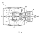
Figure 1 shows a ducted fan gas turbine engine incorporating the invention; -
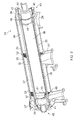
Figure 2 shows a first embodiment of the present invention; -
Figure 3 shows the tubular element of the first preferred embodiment of the present invention; -
Figure 4 shows a second embodiment of the present invention; and -
Figure 5 shows the tubular element of the second preferred embodiment of the present invention. - With reference to
Figure 1 , a ducted fan gas turbine engine incorporating the invention is generally indicated at 10 and has a principal and rotational axis X-X. The engine comprises, in axial flow series, anair intake 11, apropulsive fan 12, anintermediate pressure compressor 13, a high-pressure compressor 14,combustion equipment 15, a high-pressure turbine 16, anintermediate pressure turbine 17, a low-pressure turbine 18 and a coreengine exhaust nozzle 19. Anacelle 21 generally surrounds theengine 10 and defines theintake 11, abypass duct 22 and abypass exhaust nozzle 23. - During operation, air entering the
intake 11 is accelerated by thefan 12 to produce two air flows: a first air flow A into theintermediate pressure compressor 13 and a second air flow B which passes through thebypass duct 22 to provide propulsive thrust. Theintermediate pressure compressor 13 compresses the air flow A directed into it before delivering that air to thehigh pressure compressor 14 where further compression takes place. - The compressed air exhausted from the high-
pressure compressor 14 is directed into thecombustion equipment 15 where it is mixed with fuel and the mixture combusted. The resultant hot combustion products then expand through, and thereby drive the high, intermediate and low-pressure turbines nozzle 19 to provide additional propulsive thrust. The high, intermediate and low-pressure turbines respectively drive the high andintermediate pressure compressors fan 12 by suitable interconnecting shafts. - A heat exchanger according to the present invention may be provided on a casing surrounding the
combustion equipment 15. -
Figures 2 and3 show a first preferred embodiment of the present invention. - The
heat exchanger 24 comprises anouter casing 25 which has a tubular (cylindrical)portion 26 extending between twoend housings end housing 28 is integral with thetubular portion 26 which facilitates manufacture. - The
outer casing 25 comprises afirst outlet 29, asecond outlet 30 and aninlet 31. Theinlet 31 is axially spaced between thefirst outlet 29 and thesecond outlet 30. Theinlet 31 is equally spaced from thefirst outlet 29 and thesecond outlet 30. - The
heat exchanger 24 further comprises a tubular element 32 (shown in isolation inFigure 3 ) within saidouter casing 25. Thetubular element 32 is cylindrical and axially aligned with (and spaced from) thecylindrical portion 26 of theouter casing 25. - The
tubular element 32 has anouter surface 33 and aninner surface 34. - The
end housings outer casing 25 are sealed onto theouter surface 33 of thetubular element 32 by a respective metallic multiple piston ring seal. - The
outer casing 25 andouter surface 33 of thetubular element 32 define a firstannular passage 35 through which a high pressure air flow path extends. - The first
annular passage 35/first fluid flow path comprises afirst portion 36 extending from theinlet 31 to thefirst outlet 29 and asecond portion 37 extending (in an opposite axial direction) from theinlet 31 to thesecond outlet 30. - The heat exchanger further comprises an
inner sleeve 38 within thetubular element 32. Theinner sleeve 38 is a cylindrical sleeve and is axially aligned with (and spaced from) thetubular element 32. - The
inner sleeve 38 andinner surface 34 of thetubular element 32 define a secondannular passage 39 through which a fuel flow path extends. - The
inner sleeve 38 has a shorter axial length than thetubular element 32 such that the firstaxial end 40 and secondaxial end 41 of theinner sleeve 38 are contained within thetubular element 32. - The second
annular passage 39 is in fluid communication with aninlet adapter 42 at aninlet end 43 of theheat exchanger 24 and anoutlet adapter 44 at anoutlet end 45 of theheat exchanger 24. Theinlet adapter 42 is for connection (via appropriate tubing) to a fuel source (not shown). Theoutlet adapter 44 is for connection (via appropriate tubing) to the combustion equipment 15 (shown inFigure 1 ). - The
adapters inner surface 34 of the tubular element. Theinlet adapter 42 is further sealed against theinner surface 34 of thetubular element 32 by an elastomeric O-ring 45 which is compressed between theinlet adapter 42, theinner surface 34 of thetubular element 32 and aninlet spacer 46. Theoutlet adapter 44 is further sealed against theinner surface 34 of thetubular element 32 by an elastomeric O-ring 47 which is compressed between theoutlet adapter 44, theinner surface 34 of thetubular element 32 and anoutlet spacer 48. These threads and o-rings seal the secondannular passage 39 within thetubular element 32. - Fluid communication between the second
annular passage 39 and the inlet/outlet adapters outs axial end inner sleeve 38. There are four such cut-outs, circumferentially spaced around theinner sleeve 28 at eachaxial end - Each cut-
out inner sleeve 38 at the respectiveaxial end inner sleeve 38. The bore of theinner sleeve 38 is in fluid communication with theinlet adapter 42 at theinlet end 43 of theheat exchanger 24 and in fluid communication with theoutlet adapter 44 at the outlet end 45 of theheat exchanger 24. - A blanking
wall 51 is provided across the bore of theinner sleeve 38 proximal the secondaxial end 41 of theinner sleeve 38. - The first
annular passage 35 is divided by axially extending, circumferentially spaced radialouter fins 52 which are machined (using electro-discharge wire cutting) onto and therefore integral with theouter surface 33 of thetubular element 32. Theouter fins 52 divide the first annular passage/first fluid flow path into a series of axially aligned channels. - In the first embodiment, the second
annular passage 39 is divided by axially extending, circumferentially spaced radialinner fins 53. Theinner fins 53 are integral with theinner surface 34 of thetubular element 32 and are formed by machining theinner surface 34 of thetubular element 32 by electro-discharge wire cutting. - The
inner fins 53 divide the secondannular passage 39/second fluid flow path into a series of axially aligned channels extending from the firstaxial end 40 of theinner sleeve 38 to the secondaxial end 41 of theinner sleeve 38. - The axially extending, circumferentially spaced radial
inner fins 53 are adapted to divide the second annular passage into a plurality of convoluted channels. Each convoluted channel has aninlet 54 at the firstaxial end 40 of theinner sleeve 32, a series of axially alignedportions 55 with adjacent axially aligned portions being interconnected proximal the axial ends 40, 41 of theinner sleeve 32 and anoutlet 56 at the secondaxial end 41 of theinner sleeve 32. In this embodiment, there are three axially aligned portions. - There are four such convoluted channels in this embodiment and each
inlet 54 andoutlet 56 are aligned with the fourrespective cut outs inner sleeve 38. - In use, the
inlet adapter 42 is connected (via appropriate tubing) to a fuel source. Fuel enters theadapter 42 and passes through the fourcut outs 49 in the firstaxial end 40 of theinner sleeve 38 to enter the secondannular passage 39 between theinner sleeve 38 and theinner surface 34 of thetubular element 32. The fuel is channelled in a convoluted fuel flow path by theinner fins 53, the fuel passing along the three axially alignedportions 55 of the respective one of the four convoluted channels. This ensures that the fuel travels along the length of theinner sleeve 38 multiple times. - Compressed air from the
compressors annular passage 35 of theheat exchanger 24 via theinlet 31 which is spaced equidistant from thefirst outlet 29 and thesecond outlet 30. The air flow is divided between thefirst portion 36 which extends from theinlet 31 to thefirst outlet 29 and thesecond portion 37 which extends from theinlet 31 to thesecond outlet 30. The air travels along the axial channels defined by theouter fins 53 on theouter surface 33 of thetubular element 32. - Heat from the compressed air passes from the first
annular passage 35 to the secondannular passage 39 through theouter fins 52 and thetubular element 32 to heat the fuel as is passes along the convoluted channels defined by theinner fins 53. The compressed air is cooled in the process and the cooler air exiting theoutlets - A second embodiment of the present invention is shown in
Figures 4 and5 . Many features are common between the two embodiments shown and the same reference numerals are used where appropriate. - In this embodiment, the
inner surface 34 of thetubular element 32 comprises integral spirally/helically extending, circumferentially spaced radialinner fins 57 which formed into theinner surface 34 using thread milling. Theseinner fins 57 divide the secondannular passage 39 into a series of aligned spiral/helical channels extending from the firstaxial end 40 of theinner sleeve 38 to the secondaxial end 41 of theinner sleeve 38. - The second
axial end 41 of theinner sleeve 38 comprises a series ofcircular apertures 58 which provide fluid communication between the secondannular passage 39 and the outlet adapter 44 (via the bore of the inner sleeve 38). At the firstaxial end 40 of theinner sleeve 38, a cut-out 49 is provided to allow fuel to enter the second annular passage. - Fuel entering the second
annular passage 39 follows a spiral/helical path around theinside surface 34 of the tubular element, heat from the compressed air in the firstannular passage 35 being transferred across thetubular element 32 into the fuel. - While the invention has been described in conjunction with the exemplary embodiments described above, many equivalent modifications and variations will be apparent to those skilled in the art when given this disclosure. Accordingly, the exemplary embodiments of the invention set forth above are considered to be illustrative and not limiting. Various changes to the described embodiments may be made without departing from the spirit and scope of the invention.
- All references referred to above are hereby incorporated by reference.
Claims (14)
- A heat exchanger comprising:an outer casing;a tubular element within said outer casing, said tubular element having an outer surface and an inner surface;an inner sleeve within said tubular element,said outer casing and outer surface of said tubular element defining a first annular passage through which a first fluid flow path extends,said inner sleeve and inner surface of said tubular element defining a second annular passage through which a second fluid flow path extends,wherein said first annular passage is sealed against the outer surface of the tubular element and said second annular passage is sealed within the inner surface of the tubular element.
- A heat exchanger comprising:an outer casing;a tubular element within said outer casing, said tubular element having an outer surface with outer fins and an inner surface with inner fins;said outer casing and outer surface of said tubular element defining a first annular passage through which a first fluid flow path extends,said inner surface of said tubular element defining a second passage through which a second fluid flow path extends,wherein said outer fins are integral with the outer surface of the tubular element and/or the inner fins are integral with the inner surface of the tubular element.
- A heat exchanger according to claim 1 or claim 2 wherein said outer surface of said tubular element comprises axially extending, circumferentially spaced radial outer fins.
- A heat exchanger according to any one of the preceding claims wherein the inner surface of the tubular element comprises axially extending, circumferentially spaced radial inner fins.
- A heat exchanger according to claim 4 wherein the axially extending, circumferentially spaced radial inner fins are adapted to divide the second fluid flow path into a plurality of convoluted channels, each convoluted channel having an inlet, a series of axially aligned portions with adjacent axially aligned portions being interconnected at their axial ends and an outlet.
- A heat exchanger according to any one of claims 1 to 3 wherein the inner surface of the tubular element comprises spirally/helically extending, circumferentially spaced radial inner fins.
- A heat exchanger according to any one of claim 3 to 6 wherein the tubular element and inner and/or outer fins are a single, unitary element.
- A heat exchanger according to any one of the preceding claims wherein the outer casing is sealed to the outer surface of the tubular element.
- A heat exchanger according to any one of the preceding claims wherein the outer casing comprises a first outlet, a second outlet and an inlet, the inlet being axially spaced between the first outlet and the second outlet such that the first annular passage/first fluid flow path comprises a first portion extending from the inlet to the first outlet and a second portion extending in an opposite axial direction from the inlet to the second outlet.
- A heat exchanger according to claim 1 or any one of claims 3 to 8 wherein the inner sleeve has a shorter axial length than the tubular element.
- A heat exchanger according to claim 1 or any of claims 3 to 9 wherein the second annular passage is in fluid communication with an inlet adapter at an inlet end of the heat exchanger and an outlet adapter at an outlet end of the heat exchanger and wherein the inlet and outlet adapters are sealed against the inner surface of the tubular element.
- A heat exchanger according to any one of the preceding claims wherein the first annular passage is sealed against the outer surface of the tubular element by a mechanical seal and/or the second passage/second annular passage is sealed within the tubular element by a mechanical seal.
- A gas turbine engine comprising a heat exchanger according to any one of claims 1 to 12.
- Use of a heat exchanger according to any one of claims 1 to 12 wherein the first fluid is compressed air and the second fluid is fuel.
Applications Claiming Priority (1)
| Application Number | Priority Date | Filing Date | Title |
|---|---|---|---|
| GBGB1419963.2A GB201419963D0 (en) | 2014-11-10 | 2014-11-10 | Heat exchanger |
Publications (3)
| Publication Number | Publication Date |
|---|---|
| EP3026384A2 true EP3026384A2 (en) | 2016-06-01 |
| EP3026384A3 EP3026384A3 (en) | 2016-08-31 |
| EP3026384B1 EP3026384B1 (en) | 2017-07-26 |
Family
ID=52118248
Family Applications (1)
| Application Number | Title | Priority Date | Filing Date |
|---|---|---|---|
| EP15189507.5A Active EP3026384B1 (en) | 2014-11-10 | 2015-10-13 | Heat exchanger |
Country Status (3)
| Country | Link |
|---|---|
| US (1) | US10221768B2 (en) |
| EP (1) | EP3026384B1 (en) |
| GB (1) | GB201419963D0 (en) |
Cited By (4)
| Publication number | Priority date | Publication date | Assignee | Title |
|---|---|---|---|---|
| EP3521742A1 (en) * | 2018-02-01 | 2019-08-07 | Hamilton Sundstrand Corporation | Heat exchanger |
| CN111351378A (en) * | 2018-12-21 | 2020-06-30 | 赛峰航空助推器股份有限公司 | Fuel oil heat exchanger |
| EP3719280A1 (en) * | 2019-04-03 | 2020-10-07 | Airbus Operations, S.L.U. | Flow mixer duct for a bleed system |
| EP4481314A1 (en) * | 2023-06-08 | 2024-12-25 | RTX Corporation | Composite heat exchange apparatus for a turbine engine |
Families Citing this family (10)
| Publication number | Priority date | Publication date | Assignee | Title |
|---|---|---|---|---|
| US10103081B2 (en) * | 2014-09-08 | 2018-10-16 | Ashwin Bharadwaj | Heat sink |
| CN110044199B (en) * | 2019-05-23 | 2023-10-17 | 中国船舶重工集团公司第七0三研究所 | Gas turbine gas air heat exchange core and heat exchanger |
| US11274602B2 (en) | 2019-05-24 | 2022-03-15 | Pratt & Whitney Canada Corp. | Air cooler for gas turbine engine |
| US12140077B2 (en) | 2020-01-03 | 2024-11-12 | Rtx Corporation | Aircraft heat exchanger assembly |
| EP3911908B1 (en) | 2020-01-19 | 2023-07-12 | Raytheon Technologies Corporation | Aircraft heat exchanger |
| US11300360B2 (en) * | 2020-01-24 | 2022-04-12 | Hamilton Sundstrand Corporation | Pressure vessel with barrier passage containing fire suppressant elements |
| US12203708B2 (en) * | 2021-02-02 | 2025-01-21 | Pratt & Whitney Canada Corp. | Heat exchanger and associated method of assembly |
| US11614287B2 (en) * | 2021-06-24 | 2023-03-28 | Darby Renewable Energy Design Systems Inc. | Heat exchanger |
| US11555450B1 (en) * | 2021-08-19 | 2023-01-17 | Collins Engine Nozzles, Inc. | Fuel injectors with heat exchangers |
| US12215930B2 (en) | 2022-10-06 | 2025-02-04 | Rtx Corporation | Tube-in-tube unified shell heat exchanger |
Family Cites Families (16)
| Publication number | Priority date | Publication date | Assignee | Title |
|---|---|---|---|---|
| GB935091A (en) * | 1959-12-11 | 1963-08-28 | Andre Huet | Improvements in or relating to tubular heat exchangers |
| GB2065861A (en) * | 1979-12-14 | 1981-07-01 | Aerco Int Inc | Countercurrent heat exchanger with a dimpled membrane |
| US4548257A (en) | 1982-02-23 | 1985-10-22 | Williamson William R | Bayonet tube heat exchanger |
| EP0138677A3 (en) | 1983-09-21 | 1985-05-22 | Office National d'Etudes et de Recherches Aérospatiales (O.N.E.R.A.) | Heat-exchanger tubes, heat-exchangers provided therewith and gas-turbine plants comprising such a heat-exchanger |
| WO1991002146A1 (en) * | 1989-07-28 | 1991-02-21 | Nomac Energy Systems, Inc. | Circumferential heat exchanger |
| EP0449124B1 (en) | 1990-03-29 | 1995-05-24 | Hubert Vogt | Annular space heat exchanger |
| US5317877A (en) * | 1992-08-03 | 1994-06-07 | General Electric Company | Intercooled turbine blade cooling air feed system |
| FR2787563B1 (en) | 1998-12-22 | 2001-02-02 | Db Ind | ANNULAR TEMPERATURE EXCHANGER |
| US7322404B2 (en) | 2004-02-18 | 2008-01-29 | Renewability Energy Inc. | Helical coil-on-tube heat exchanger |
| US8048583B2 (en) * | 2006-07-20 | 2011-11-01 | Modine Manufacturing Company | Compact air preheater for solid oxide fuel cell systems |
| JP2009162395A (en) * | 2007-12-28 | 2009-07-23 | Showa Denko Kk | Double-wall-tube heat exchanger |
| US8028410B2 (en) * | 2008-12-08 | 2011-10-04 | Randy Thompson | Gas turbine regenerator apparatus and method of manufacture |
| WO2012116448A1 (en) * | 2011-03-01 | 2012-09-07 | Dana Canada Corporation | Coaxial gas-liquid heat exchanger with thermal expansion connector |
| US8943827B2 (en) * | 2011-05-31 | 2015-02-03 | Pratt & Whitney Canada Corp. | Fuel air heat exchanger |
| CN202973541U (en) | 2012-11-30 | 2013-06-05 | 苏宇贵 | Three-sleeve heat exchanger and heat pump water heater using heat exchanger |
| US9664451B2 (en) * | 2013-03-04 | 2017-05-30 | Rocky Research | Co-fired absorption system generator |
-
2014
- 2014-11-10 GB GBGB1419963.2A patent/GB201419963D0/en not_active Ceased
-
2015
- 2015-10-13 EP EP15189507.5A patent/EP3026384B1/en active Active
- 2015-10-13 US US14/881,722 patent/US10221768B2/en active Active
Cited By (6)
| Publication number | Priority date | Publication date | Assignee | Title |
|---|---|---|---|---|
| EP3521742A1 (en) * | 2018-02-01 | 2019-08-07 | Hamilton Sundstrand Corporation | Heat exchanger |
| US10866030B2 (en) | 2018-02-01 | 2020-12-15 | Hamilton Sunstrand Corporation | Heat exchanger |
| CN111351378A (en) * | 2018-12-21 | 2020-06-30 | 赛峰航空助推器股份有限公司 | Fuel oil heat exchanger |
| EP3719280A1 (en) * | 2019-04-03 | 2020-10-07 | Airbus Operations, S.L.U. | Flow mixer duct for a bleed system |
| US11619456B2 (en) | 2019-04-03 | 2023-04-04 | Airbus Operations S.L.U. | Flow mixer duct for a bleed system |
| EP4481314A1 (en) * | 2023-06-08 | 2024-12-25 | RTX Corporation | Composite heat exchange apparatus for a turbine engine |
Also Published As
| Publication number | Publication date |
|---|---|
| EP3026384B1 (en) | 2017-07-26 |
| US10221768B2 (en) | 2019-03-05 |
| GB201419963D0 (en) | 2014-12-24 |
| US20160131040A1 (en) | 2016-05-12 |
| EP3026384A3 (en) | 2016-08-31 |
Similar Documents
| Publication | Publication Date | Title |
|---|---|---|
| US10221768B2 (en) | Heat exchanger having a coaxial or concentric tube construction | |
| US9777963B2 (en) | Method and system for radial tubular heat exchangers | |
| EP3008310B1 (en) | Curved plate/fin heat exchanger | |
| EP3828399B1 (en) | Internal fuel/air heat exchangers | |
| CN109415945B (en) | Modular annular heat exchanger | |
| EP2530280B1 (en) | Fuel air heat exchanger | |
| EP2927426B1 (en) | Cooling system with a bearing compartment bypass and corresponding method | |
| US10830147B2 (en) | Heat exchanger integrated with fuel nozzle | |
| SE512582C2 (en) | Method for manufacturing annular heat exchanger for gas turbine engines | |
| EP3358140B1 (en) | Fitting for multiwall tube | |
| US7895823B2 (en) | Heat exchanger for a rocket engine | |
| EP2657610A2 (en) | A combustor and a method for assembling the combustor | |
| EP2657456A2 (en) | Separable inter shaft seal assembly for a gas turbine engine | |
| EP3239580B1 (en) | Gas turbine engine combustion equipment with flexible hoses | |
| US12203708B2 (en) | Heat exchanger and associated method of assembly | |
| EP3460218B1 (en) | Transfer tubes | |
| BR102015015753A2 (en) | HEAT EXCHANGER ASSEMBLY AND METHOD FOR ARMING A HEAT EXCHANGER | |
| GB2519149A (en) | Ducts for engines | |
| WO2015052466A1 (en) | Ducts for engines | |
| BR102015031136A2 (en) | CONNECTION PROVISION FOR TRANSMISSION TORQUE FOR USE IN TRAINING TRAIN OF AN AUTOMOBILE VEHICLE |
Legal Events
| Date | Code | Title | Description |
|---|---|---|---|
| PUAI | Public reference made under article 153(3) epc to a published international application that has entered the european phase |
Free format text: ORIGINAL CODE: 0009012 |
|
| AK | Designated contracting states |
Kind code of ref document: A2 Designated state(s): AL AT BE BG CH CY CZ DE DK EE ES FI FR GB GR HR HU IE IS IT LI LT LU LV MC MK MT NL NO PL PT RO RS SE SI SK SM TR |
|
| AX | Request for extension of the european patent |
Extension state: BA ME |
|
| PUAL | Search report despatched |
Free format text: ORIGINAL CODE: 0009013 |
|
| AK | Designated contracting states |
Kind code of ref document: A3 Designated state(s): AL AT BE BG CH CY CZ DE DK EE ES FI FR GB GR HR HU IE IS IT LI LT LU LV MC MK MT NL NO PL PT RO RS SE SI SK SM TR |
|
| AX | Request for extension of the european patent |
Extension state: BA ME |
|
| RIC1 | Information provided on ipc code assigned before grant |
Ipc: F02C 7/224 20060101ALI20160726BHEP Ipc: F28D 7/10 20060101AFI20160726BHEP |
|
| STAA | Information on the status of an ep patent application or granted ep patent |
Free format text: STATUS: REQUEST FOR EXAMINATION WAS MADE |
|
| 17P | Request for examination filed |
Effective date: 20170221 |
|
| RBV | Designated contracting states (corrected) |
Designated state(s): AL AT BE BG CH CY CZ DE DK EE ES FI FR GB GR HR HU IE IS IT LI LT LU LV MC MK MT NL NO PL PT RO RS SE SI SK SM TR |
|
| GRAP | Despatch of communication of intention to grant a patent |
Free format text: ORIGINAL CODE: EPIDOSNIGR1 |
|
| STAA | Information on the status of an ep patent application or granted ep patent |
Free format text: STATUS: GRANT OF PATENT IS INTENDED |
|
| RIC1 | Information provided on ipc code assigned before grant |
Ipc: F28D 7/10 20060101AFI20170407BHEP Ipc: F02C 7/18 20060101ALI20170407BHEP Ipc: F02C 7/224 20060101ALI20170407BHEP |
|
| INTG | Intention to grant announced |
Effective date: 20170516 |
|
| GRAS | Grant fee paid |
Free format text: ORIGINAL CODE: EPIDOSNIGR3 |
|
| GRAA | (expected) grant |
Free format text: ORIGINAL CODE: 0009210 |
|
| STAA | Information on the status of an ep patent application or granted ep patent |
Free format text: STATUS: THE PATENT HAS BEEN GRANTED |
|
| AK | Designated contracting states |
Kind code of ref document: B1 Designated state(s): AL AT BE BG CH CY CZ DE DK EE ES FI FR GB GR HR HU IE IS IT LI LT LU LV MC MK MT NL NO PL PT RO RS SE SI SK SM TR |
|
| REG | Reference to a national code |
Ref country code: GB Ref legal event code: FG4D |
|
| REG | Reference to a national code |
Ref country code: CH Ref legal event code: EP |
|
| REG | Reference to a national code |
Ref country code: AT Ref legal event code: REF Ref document number: 912715 Country of ref document: AT Kind code of ref document: T Effective date: 20170815 |
|
| REG | Reference to a national code |
Ref country code: IE Ref legal event code: FG4D |
|
| REG | Reference to a national code |
Ref country code: DE Ref legal event code: R096 Ref document number: 602015003738 Country of ref document: DE |
|
| REG | Reference to a national code |
Ref country code: FR Ref legal event code: PLFP Year of fee payment: 3 |
|
| REG | Reference to a national code |
Ref country code: NL Ref legal event code: MP Effective date: 20170726 |
|
| REG | Reference to a national code |
Ref country code: LT Ref legal event code: MG4D |
|
| REG | Reference to a national code |
Ref country code: AT Ref legal event code: MK05 Ref document number: 912715 Country of ref document: AT Kind code of ref document: T Effective date: 20170726 |
|
| PG25 | Lapsed in a contracting state [announced via postgrant information from national office to epo] |
Ref country code: SE Free format text: LAPSE BECAUSE OF FAILURE TO SUBMIT A TRANSLATION OF THE DESCRIPTION OR TO PAY THE FEE WITHIN THE PRESCRIBED TIME-LIMIT Effective date: 20170726 Ref country code: HR Free format text: LAPSE BECAUSE OF FAILURE TO SUBMIT A TRANSLATION OF THE DESCRIPTION OR TO PAY THE FEE WITHIN THE PRESCRIBED TIME-LIMIT Effective date: 20170726 Ref country code: NL Free format text: LAPSE BECAUSE OF FAILURE TO SUBMIT A TRANSLATION OF THE DESCRIPTION OR TO PAY THE FEE WITHIN THE PRESCRIBED TIME-LIMIT Effective date: 20170726 Ref country code: NO Free format text: LAPSE BECAUSE OF FAILURE TO SUBMIT A TRANSLATION OF THE DESCRIPTION OR TO PAY THE FEE WITHIN THE PRESCRIBED TIME-LIMIT Effective date: 20171026 Ref country code: LT Free format text: LAPSE BECAUSE OF FAILURE TO SUBMIT A TRANSLATION OF THE DESCRIPTION OR TO PAY THE FEE WITHIN THE PRESCRIBED TIME-LIMIT Effective date: 20170726 Ref country code: FI Free format text: LAPSE BECAUSE OF FAILURE TO SUBMIT A TRANSLATION OF THE DESCRIPTION OR TO PAY THE FEE WITHIN THE PRESCRIBED TIME-LIMIT Effective date: 20170726 Ref country code: AT Free format text: LAPSE BECAUSE OF FAILURE TO SUBMIT A TRANSLATION OF THE DESCRIPTION OR TO PAY THE FEE WITHIN THE PRESCRIBED TIME-LIMIT Effective date: 20170726 |
|
| PG25 | Lapsed in a contracting state [announced via postgrant information from national office to epo] |
Ref country code: RS Free format text: LAPSE BECAUSE OF FAILURE TO SUBMIT A TRANSLATION OF THE DESCRIPTION OR TO PAY THE FEE WITHIN THE PRESCRIBED TIME-LIMIT Effective date: 20170726 Ref country code: BG Free format text: LAPSE BECAUSE OF FAILURE TO SUBMIT A TRANSLATION OF THE DESCRIPTION OR TO PAY THE FEE WITHIN THE PRESCRIBED TIME-LIMIT Effective date: 20171026 Ref country code: GR Free format text: LAPSE BECAUSE OF FAILURE TO SUBMIT A TRANSLATION OF THE DESCRIPTION OR TO PAY THE FEE WITHIN THE PRESCRIBED TIME-LIMIT Effective date: 20171027 Ref country code: IS Free format text: LAPSE BECAUSE OF FAILURE TO SUBMIT A TRANSLATION OF THE DESCRIPTION OR TO PAY THE FEE WITHIN THE PRESCRIBED TIME-LIMIT Effective date: 20171126 Ref country code: ES Free format text: LAPSE BECAUSE OF FAILURE TO SUBMIT A TRANSLATION OF THE DESCRIPTION OR TO PAY THE FEE WITHIN THE PRESCRIBED TIME-LIMIT Effective date: 20170726 Ref country code: LV Free format text: LAPSE BECAUSE OF FAILURE TO SUBMIT A TRANSLATION OF THE DESCRIPTION OR TO PAY THE FEE WITHIN THE PRESCRIBED TIME-LIMIT Effective date: 20170726 Ref country code: PL Free format text: LAPSE BECAUSE OF FAILURE TO SUBMIT A TRANSLATION OF THE DESCRIPTION OR TO PAY THE FEE WITHIN THE PRESCRIBED TIME-LIMIT Effective date: 20170726 |
|
| PG25 | Lapsed in a contracting state [announced via postgrant information from national office to epo] |
Ref country code: DK Free format text: LAPSE BECAUSE OF FAILURE TO SUBMIT A TRANSLATION OF THE DESCRIPTION OR TO PAY THE FEE WITHIN THE PRESCRIBED TIME-LIMIT Effective date: 20170726 Ref country code: RO Free format text: LAPSE BECAUSE OF FAILURE TO SUBMIT A TRANSLATION OF THE DESCRIPTION OR TO PAY THE FEE WITHIN THE PRESCRIBED TIME-LIMIT Effective date: 20170726 Ref country code: CZ Free format text: LAPSE BECAUSE OF FAILURE TO SUBMIT A TRANSLATION OF THE DESCRIPTION OR TO PAY THE FEE WITHIN THE PRESCRIBED TIME-LIMIT Effective date: 20170726 |
|
| REG | Reference to a national code |
Ref country code: DE Ref legal event code: R097 Ref document number: 602015003738 Country of ref document: DE |
|
| PG25 | Lapsed in a contracting state [announced via postgrant information from national office to epo] |
Ref country code: MC Free format text: LAPSE BECAUSE OF FAILURE TO SUBMIT A TRANSLATION OF THE DESCRIPTION OR TO PAY THE FEE WITHIN THE PRESCRIBED TIME-LIMIT Effective date: 20170726 Ref country code: SK Free format text: LAPSE BECAUSE OF FAILURE TO SUBMIT A TRANSLATION OF THE DESCRIPTION OR TO PAY THE FEE WITHIN THE PRESCRIBED TIME-LIMIT Effective date: 20170726 Ref country code: IT Free format text: LAPSE BECAUSE OF FAILURE TO SUBMIT A TRANSLATION OF THE DESCRIPTION OR TO PAY THE FEE WITHIN THE PRESCRIBED TIME-LIMIT Effective date: 20170726 Ref country code: SM Free format text: LAPSE BECAUSE OF FAILURE TO SUBMIT A TRANSLATION OF THE DESCRIPTION OR TO PAY THE FEE WITHIN THE PRESCRIBED TIME-LIMIT Effective date: 20170726 Ref country code: EE Free format text: LAPSE BECAUSE OF FAILURE TO SUBMIT A TRANSLATION OF THE DESCRIPTION OR TO PAY THE FEE WITHIN THE PRESCRIBED TIME-LIMIT Effective date: 20170726 |
|
| PLBE | No opposition filed within time limit |
Free format text: ORIGINAL CODE: 0009261 |
|
| STAA | Information on the status of an ep patent application or granted ep patent |
Free format text: STATUS: NO OPPOSITION FILED WITHIN TIME LIMIT |
|
| 26N | No opposition filed |
Effective date: 20180430 |
|
| REG | Reference to a national code |
Ref country code: IE Ref legal event code: MM4A |
|
| PG25 | Lapsed in a contracting state [announced via postgrant information from national office to epo] |
Ref country code: LU Free format text: LAPSE BECAUSE OF NON-PAYMENT OF DUE FEES Effective date: 20171013 |
|
| REG | Reference to a national code |
Ref country code: BE Ref legal event code: MM Effective date: 20171031 |
|
| PG25 | Lapsed in a contracting state [announced via postgrant information from national office to epo] |
Ref country code: BE Free format text: LAPSE BECAUSE OF NON-PAYMENT OF DUE FEES Effective date: 20171031 Ref country code: SI Free format text: LAPSE BECAUSE OF FAILURE TO SUBMIT A TRANSLATION OF THE DESCRIPTION OR TO PAY THE FEE WITHIN THE PRESCRIBED TIME-LIMIT Effective date: 20170726 |
|
| PG25 | Lapsed in a contracting state [announced via postgrant information from national office to epo] |
Ref country code: MT Free format text: LAPSE BECAUSE OF NON-PAYMENT OF DUE FEES Effective date: 20171013 |
|
| REG | Reference to a national code |
Ref country code: FR Ref legal event code: PLFP Year of fee payment: 4 |
|
| PG25 | Lapsed in a contracting state [announced via postgrant information from national office to epo] |
Ref country code: IE Free format text: LAPSE BECAUSE OF NON-PAYMENT OF DUE FEES Effective date: 20171013 |
|
| REG | Reference to a national code |
Ref country code: CH Ref legal event code: PL |
|
| PG25 | Lapsed in a contracting state [announced via postgrant information from national office to epo] |
Ref country code: HU Free format text: LAPSE BECAUSE OF FAILURE TO SUBMIT A TRANSLATION OF THE DESCRIPTION OR TO PAY THE FEE WITHIN THE PRESCRIBED TIME-LIMIT; INVALID AB INITIO Effective date: 20151013 |
|
| PG25 | Lapsed in a contracting state [announced via postgrant information from national office to epo] |
Ref country code: LI Free format text: LAPSE BECAUSE OF NON-PAYMENT OF DUE FEES Effective date: 20181031 Ref country code: CH Free format text: LAPSE BECAUSE OF NON-PAYMENT OF DUE FEES Effective date: 20181031 |
|
| PG25 | Lapsed in a contracting state [announced via postgrant information from national office to epo] |
Ref country code: CY Free format text: LAPSE BECAUSE OF FAILURE TO SUBMIT A TRANSLATION OF THE DESCRIPTION OR TO PAY THE FEE WITHIN THE PRESCRIBED TIME-LIMIT Effective date: 20170726 |
|
| PG25 | Lapsed in a contracting state [announced via postgrant information from national office to epo] |
Ref country code: MK Free format text: LAPSE BECAUSE OF FAILURE TO SUBMIT A TRANSLATION OF THE DESCRIPTION OR TO PAY THE FEE WITHIN THE PRESCRIBED TIME-LIMIT Effective date: 20170726 |
|
| PG25 | Lapsed in a contracting state [announced via postgrant information from national office to epo] |
Ref country code: TR Free format text: LAPSE BECAUSE OF FAILURE TO SUBMIT A TRANSLATION OF THE DESCRIPTION OR TO PAY THE FEE WITHIN THE PRESCRIBED TIME-LIMIT Effective date: 20170726 |
|
| PG25 | Lapsed in a contracting state [announced via postgrant information from national office to epo] |
Ref country code: PT Free format text: LAPSE BECAUSE OF FAILURE TO SUBMIT A TRANSLATION OF THE DESCRIPTION OR TO PAY THE FEE WITHIN THE PRESCRIBED TIME-LIMIT Effective date: 20170726 |
|
| PG25 | Lapsed in a contracting state [announced via postgrant information from national office to epo] |
Ref country code: AL Free format text: LAPSE BECAUSE OF FAILURE TO SUBMIT A TRANSLATION OF THE DESCRIPTION OR TO PAY THE FEE WITHIN THE PRESCRIBED TIME-LIMIT Effective date: 20170726 |
|
| P01 | Opt-out of the competence of the unified patent court (upc) registered |
Effective date: 20230528 |
|
| PGFP | Annual fee paid to national office [announced via postgrant information from national office to epo] |
Ref country code: DE Payment date: 20251028 Year of fee payment: 11 |
|
| PGFP | Annual fee paid to national office [announced via postgrant information from national office to epo] |
Ref country code: GB Payment date: 20251023 Year of fee payment: 11 |
|
| PGFP | Annual fee paid to national office [announced via postgrant information from national office to epo] |
Ref country code: FR Payment date: 20251027 Year of fee payment: 11 |