EP3026283A1 - Rolling bearing assembly - Google Patents
Rolling bearing assembly Download PDFInfo
- Publication number
- EP3026283A1 EP3026283A1 EP14306915.1A EP14306915A EP3026283A1 EP 3026283 A1 EP3026283 A1 EP 3026283A1 EP 14306915 A EP14306915 A EP 14306915A EP 3026283 A1 EP3026283 A1 EP 3026283A1
- Authority
- EP
- European Patent Office
- Prior art keywords
- rolling bearing
- bearing assembly
- sleeve
- assembly according
- housing
- Prior art date
- Legal status (The legal status is an assumption and is not a legal conclusion. Google has not performed a legal analysis and makes no representation as to the accuracy of the status listed.)
- Granted
Links
Images


Classifications
-
- F—MECHANICAL ENGINEERING; LIGHTING; HEATING; WEAPONS; BLASTING
- F16—ENGINEERING ELEMENTS AND UNITS; GENERAL MEASURES FOR PRODUCING AND MAINTAINING EFFECTIVE FUNCTIONING OF MACHINES OR INSTALLATIONS; THERMAL INSULATION IN GENERAL
- F16C—SHAFTS; FLEXIBLE SHAFTS; ELEMENTS OR CRANKSHAFT MECHANISMS; ROTARY BODIES OTHER THAN GEARING ELEMENTS; BEARINGS
- F16C41/00—Other accessories, e.g. devices integrated in the bearing not relating to the bearing function as such
-
- F—MECHANICAL ENGINEERING; LIGHTING; HEATING; WEAPONS; BLASTING
- F16—ENGINEERING ELEMENTS AND UNITS; GENERAL MEASURES FOR PRODUCING AND MAINTAINING EFFECTIVE FUNCTIONING OF MACHINES OR INSTALLATIONS; THERMAL INSULATION IN GENERAL
- F16C—SHAFTS; FLEXIBLE SHAFTS; ELEMENTS OR CRANKSHAFT MECHANISMS; ROTARY BODIES OTHER THAN GEARING ELEMENTS; BEARINGS
- F16C41/00—Other accessories, e.g. devices integrated in the bearing not relating to the bearing function as such
- F16C41/007—Encoders, e.g. parts with a plurality of alternating magnetic poles
-
- F—MECHANICAL ENGINEERING; LIGHTING; HEATING; WEAPONS; BLASTING
- F16—ENGINEERING ELEMENTS AND UNITS; GENERAL MEASURES FOR PRODUCING AND MAINTAINING EFFECTIVE FUNCTIONING OF MACHINES OR INSTALLATIONS; THERMAL INSULATION IN GENERAL
- F16C—SHAFTS; FLEXIBLE SHAFTS; ELEMENTS OR CRANKSHAFT MECHANISMS; ROTARY BODIES OTHER THAN GEARING ELEMENTS; BEARINGS
- F16C19/00—Bearings with rolling contact, for exclusively rotary movement
- F16C19/02—Bearings with rolling contact, for exclusively rotary movement with bearing balls essentially of the same size in one or more circular rows
- F16C19/14—Bearings with rolling contact, for exclusively rotary movement with bearing balls essentially of the same size in one or more circular rows for both radial and axial load
- F16C19/16—Bearings with rolling contact, for exclusively rotary movement with bearing balls essentially of the same size in one or more circular rows for both radial and axial load with a single row of balls
-
- F—MECHANICAL ENGINEERING; LIGHTING; HEATING; WEAPONS; BLASTING
- F16—ENGINEERING ELEMENTS AND UNITS; GENERAL MEASURES FOR PRODUCING AND MAINTAINING EFFECTIVE FUNCTIONING OF MACHINES OR INSTALLATIONS; THERMAL INSULATION IN GENERAL
- F16C—SHAFTS; FLEXIBLE SHAFTS; ELEMENTS OR CRANKSHAFT MECHANISMS; ROTARY BODIES OTHER THAN GEARING ELEMENTS; BEARINGS
- F16C25/00—Bearings for exclusively rotary movement adjustable for wear or play
- F16C25/06—Ball or roller bearings
- F16C25/08—Ball or roller bearings self-adjusting
- F16C25/083—Ball or roller bearings self-adjusting with resilient means acting axially on a race ring to preload the bearing
-
- F—MECHANICAL ENGINEERING; LIGHTING; HEATING; WEAPONS; BLASTING
- F16—ENGINEERING ELEMENTS AND UNITS; GENERAL MEASURES FOR PRODUCING AND MAINTAINING EFFECTIVE FUNCTIONING OF MACHINES OR INSTALLATIONS; THERMAL INSULATION IN GENERAL
- F16C—SHAFTS; FLEXIBLE SHAFTS; ELEMENTS OR CRANKSHAFT MECHANISMS; ROTARY BODIES OTHER THAN GEARING ELEMENTS; BEARINGS
- F16C33/00—Parts of bearings; Special methods for making bearings or parts thereof
- F16C33/30—Parts of ball or roller bearings
-
- F—MECHANICAL ENGINEERING; LIGHTING; HEATING; WEAPONS; BLASTING
- F16—ENGINEERING ELEMENTS AND UNITS; GENERAL MEASURES FOR PRODUCING AND MAINTAINING EFFECTIVE FUNCTIONING OF MACHINES OR INSTALLATIONS; THERMAL INSULATION IN GENERAL
- F16C—SHAFTS; FLEXIBLE SHAFTS; ELEMENTS OR CRANKSHAFT MECHANISMS; ROTARY BODIES OTHER THAN GEARING ELEMENTS; BEARINGS
- F16C35/00—Rigid support of bearing units; Housings, e.g. caps, covers
- F16C35/08—Rigid support of bearing units; Housings, e.g. caps, covers for spindles
- F16C35/12—Rigid support of bearing units; Housings, e.g. caps, covers for spindles with ball or roller bearings
-
- F—MECHANICAL ENGINEERING; LIGHTING; HEATING; WEAPONS; BLASTING
- F16—ENGINEERING ELEMENTS AND UNITS; GENERAL MEASURES FOR PRODUCING AND MAINTAINING EFFECTIVE FUNCTIONING OF MACHINES OR INSTALLATIONS; THERMAL INSULATION IN GENERAL
- F16C—SHAFTS; FLEXIBLE SHAFTS; ELEMENTS OR CRANKSHAFT MECHANISMS; ROTARY BODIES OTHER THAN GEARING ELEMENTS; BEARINGS
- F16C19/00—Bearings with rolling contact, for exclusively rotary movement
- F16C19/02—Bearings with rolling contact, for exclusively rotary movement with bearing balls essentially of the same size in one or more circular rows
- F16C19/04—Bearings with rolling contact, for exclusively rotary movement with bearing balls essentially of the same size in one or more circular rows for radial load mainly
- F16C19/06—Bearings with rolling contact, for exclusively rotary movement with bearing balls essentially of the same size in one or more circular rows for radial load mainly with a single row or balls
-
- F—MECHANICAL ENGINEERING; LIGHTING; HEATING; WEAPONS; BLASTING
- F16—ENGINEERING ELEMENTS AND UNITS; GENERAL MEASURES FOR PRODUCING AND MAINTAINING EFFECTIVE FUNCTIONING OF MACHINES OR INSTALLATIONS; THERMAL INSULATION IN GENERAL
- F16C—SHAFTS; FLEXIBLE SHAFTS; ELEMENTS OR CRANKSHAFT MECHANISMS; ROTARY BODIES OTHER THAN GEARING ELEMENTS; BEARINGS
- F16C19/00—Bearings with rolling contact, for exclusively rotary movement
- F16C19/52—Bearings with rolling contact, for exclusively rotary movement with devices affected by abnormal or undesired conditions
- F16C19/525—Bearings with rolling contact, for exclusively rotary movement with devices affected by abnormal or undesired conditions related to temperature and heat, e.g. insulation
-
- F—MECHANICAL ENGINEERING; LIGHTING; HEATING; WEAPONS; BLASTING
- F16—ENGINEERING ELEMENTS AND UNITS; GENERAL MEASURES FOR PRODUCING AND MAINTAINING EFFECTIVE FUNCTIONING OF MACHINES OR INSTALLATIONS; THERMAL INSULATION IN GENERAL
- F16C—SHAFTS; FLEXIBLE SHAFTS; ELEMENTS OR CRANKSHAFT MECHANISMS; ROTARY BODIES OTHER THAN GEARING ELEMENTS; BEARINGS
- F16C2202/00—Solid materials defined by their properties
- F16C2202/20—Thermal properties
-
- F—MECHANICAL ENGINEERING; LIGHTING; HEATING; WEAPONS; BLASTING
- F16—ENGINEERING ELEMENTS AND UNITS; GENERAL MEASURES FOR PRODUCING AND MAINTAINING EFFECTIVE FUNCTIONING OF MACHINES OR INSTALLATIONS; THERMAL INSULATION IN GENERAL
- F16C—SHAFTS; FLEXIBLE SHAFTS; ELEMENTS OR CRANKSHAFT MECHANISMS; ROTARY BODIES OTHER THAN GEARING ELEMENTS; BEARINGS
- F16C2208/00—Plastics; Synthetic resins, e.g. rubbers
- F16C2208/20—Thermoplastic resins
- F16C2208/70—Polyesters, e.g. polyethylene-terephthlate [PET], polybutylene-terephthlate [PBT]
-
- F—MECHANICAL ENGINEERING; LIGHTING; HEATING; WEAPONS; BLASTING
- F16—ENGINEERING ELEMENTS AND UNITS; GENERAL MEASURES FOR PRODUCING AND MAINTAINING EFFECTIVE FUNCTIONING OF MACHINES OR INSTALLATIONS; THERMAL INSULATION IN GENERAL
- F16C—SHAFTS; FLEXIBLE SHAFTS; ELEMENTS OR CRANKSHAFT MECHANISMS; ROTARY BODIES OTHER THAN GEARING ELEMENTS; BEARINGS
- F16C2229/00—Setting preload
-
- F—MECHANICAL ENGINEERING; LIGHTING; HEATING; WEAPONS; BLASTING
- F16—ENGINEERING ELEMENTS AND UNITS; GENERAL MEASURES FOR PRODUCING AND MAINTAINING EFFECTIVE FUNCTIONING OF MACHINES OR INSTALLATIONS; THERMAL INSULATION IN GENERAL
- F16C—SHAFTS; FLEXIBLE SHAFTS; ELEMENTS OR CRANKSHAFT MECHANISMS; ROTARY BODIES OTHER THAN GEARING ELEMENTS; BEARINGS
- F16C2326/00—Articles relating to transporting
- F16C2326/20—Land vehicles
-
- F—MECHANICAL ENGINEERING; LIGHTING; HEATING; WEAPONS; BLASTING
- F16—ENGINEERING ELEMENTS AND UNITS; GENERAL MEASURES FOR PRODUCING AND MAINTAINING EFFECTIVE FUNCTIONING OF MACHINES OR INSTALLATIONS; THERMAL INSULATION IN GENERAL
- F16C—SHAFTS; FLEXIBLE SHAFTS; ELEMENTS OR CRANKSHAFT MECHANISMS; ROTARY BODIES OTHER THAN GEARING ELEMENTS; BEARINGS
- F16C35/00—Rigid support of bearing units; Housings, e.g. caps, covers
- F16C35/04—Rigid support of bearing units; Housings, e.g. caps, covers in the case of ball or roller bearings
- F16C35/06—Mounting or dismounting of ball or roller bearings; Fixing them onto shaft or in housing
- F16C35/07—Fixing them on the shaft or housing with interposition of an element
- F16C35/077—Fixing them on the shaft or housing with interposition of an element between housing and outer race ring
-
- F—MECHANICAL ENGINEERING; LIGHTING; HEATING; WEAPONS; BLASTING
- F16—ENGINEERING ELEMENTS AND UNITS; GENERAL MEASURES FOR PRODUCING AND MAINTAINING EFFECTIVE FUNCTIONING OF MACHINES OR INSTALLATIONS; THERMAL INSULATION IN GENERAL
- F16C—SHAFTS; FLEXIBLE SHAFTS; ELEMENTS OR CRANKSHAFT MECHANISMS; ROTARY BODIES OTHER THAN GEARING ELEMENTS; BEARINGS
- F16C43/00—Assembling bearings
- F16C43/04—Assembling rolling-contact bearings
Definitions
- the invention concerns a rolling bearing assembly.
- Sensor bearing units for example on two-wheelers, generally comprise a bearing and a sensor unit mounted in a housing.
- the housing is often made of a light metallic alloy including aluminium. At high temperatures, a clearance provoked by thermal dilatation can appear between the housing and the outer ring of the bearing. In such a case, the sensor body could rotate with respect to the housing.
- the plastic cap has a poor thermal dissipation capacity and increases the temperature of the bearing.
- the steel bushing is generally mounted first in the housing then the sensor bearing is mounted. This proves difficult because of the steel bushing often comprises a radial portion on one side which make uneasy the integration of the cable output.
- the aim of the invention is to provide an improved rolling bearing assembly, in which the integration of a sensor unit is easier.
- the invention concerns a rolling bearing assembly, comprising a bearing including a rotating ring and a stationary ring, a sleeve in which the stationary ring of the bearing is mounted, a housing in which the sleeve is mounted, a shaft with which the rotating ring of the bearing is coupled in rotation with respect to the housing and a sensor unit including an impulse ring coupled in rotation to the rotating ring and a sensing unit comprising at least one sensing element mounted in a sensor body.
- This rolling bearing assembly is characterized in that the sleeve, on the one hand, supports both the stationary ring of the bearing and the sensor body and, on the other hand, compensates thermal dilatations between the housing and the stationary ring.
- the integration of the sensor unit is easier than in the prior art assemblies, and improves the liability of the rolling bearing assembly.
- such a rolling bearing assembly may incorporate one or several of the following features:
- the rolling bearing assembly A represented on figure 1 is adapted to be mounted on an automotive vehicle, such as a motorcycle.
- the rolling bearing assembly A comprises a shaft C, a housing H and a sensor bearing unit U.
- the rolling bearing assembly A defines a central rotation axis X-X'.
- axial and radial are used in reference to axis X-X'.
- the sensor-bearing unit U comprises a rolling bearing 2 including a rotating ring 22 and a stationary ring 24.
- the rotating ring 22 is the inner ring
- the stationary ring 24 is the outer ring.
- the rolling bearing 2 also includes rolling elements which are balls 26 in this example.
- the rolling bearing 2 may comprise another type of rolling elements, such as rollers or needles.
- the sensor bearing unit U comprises a sensor unit 6 which includes an impulse ring 62 coupled in rotation to the rotating ring 22 and a sensing unit 64 comprising at least one sensing element 641 mounted in a sensor body 66 which is fixed to the stationary ring 24.
- the sensor body 66 comprises an axial surface 661 against which the pre-stressing element 4 exerts the pre-stressing force F4.
- the sensor body 66 transmits the pre-stressing force F4 to the stationary ring 24 thanks to an axial portion 663 which connects the axial surface 661 to the stationary ring 24.
- the sensor-bearing unit U includes a sleeve 8 in which the bearing 2 and the sensor body 66 are mounted.
- the sleeve 8 comprises a cylindrical portion 80 mounted in a bore H1 of the housing H.
- the cylindrical portion 80 defines an inner bore 800, against which the stationary ring 24 is mounted, the sleeve 8 thereby providing a support for the stationary ring 24.
- the sleeve 8 aims at compensating the effects of thermal dilatation, which can cause the bore H1 to enlarge and provoke a clearance between the stationary ring 24 and the housing H.
- the mounting of the sensor body 66 on the sleeve 8 facilitates the assembly of the rolling bearing assembly A.
- the sleeve 8 is made of a metallic material such as steel.
- the sleeve 8 can be made of a synthetic material, such as polyethylene terephthalate (PET).
- PET polyethylene terephthalate
- Such a material is light, not much expensive, provides electric isolation properties and is suitable for compensating dilatation of metallic rings such as the outer ring 24.
- the housing H may also be made of a synthetic material such as PET.
- the housing H and the sleeve 8 may both be made of a synthetic material, or only one of the housing H and the sleeve 8 may be made of a synthetic material.
- the sensor body 66 may be attached to the sleeve 8 by any convenient means selected amongst, for example, over molding, elastic mounting, gluing or welding.
- the sensor unit 6 is adapted to transmit sensed data via wire transmission.
- the sensor unit 6 therefore comprises an output transmission cable 68.
- the cable 68 extends in a slightly angled axial direction.
- the output cable 68 may extend in a purely axial direction.
- the sensor bearing unit U further includes an optional pre-stressing element 4 for pre-stressing the stationary ring 24, adapted to exert a pre-stressing force F4 between the housing H and the stationary ring 24.
- the pre-stressing element 4 is a wavy spring.
- the sleeve 8 comprises an inwardly extending radial portion 82 against which the pre-stressing element 4 is in contact.
- the axial surface 661 of the sensor body 66 and the radial portion 82 of the sleeve 8 form a chamber in which the pre-stressing element 4 is mounted.
- the radial portion 82 extends in a circumferential groove 665 of the sensor body 66, which defines the axial surface 661.
- the pre-stressing element 4 comprises alternated waves 41, which are in contact with axial surface 661, and 43, which are in contact with radial portion 82.
- a second embodiment of the invention is represented on figures 6 and 7 .
- elements similar to the first embodiment have the same references and work in the same way. Only the differences with respect to the first embodiment are described hereafter.
- the sensor unit 6 comprises an output transmission cable 69 which extend in a radial direction.
- the sensor bearing unit U may comprise no pre-stressing element 4.
- the sensor unit 6 is adapted to transmit sensed data via wireless transmission.
- the sensor body 66 may be as a whole inserted axially between the bearing 2 and the radial portion 82.
Landscapes
- Engineering & Computer Science (AREA)
- General Engineering & Computer Science (AREA)
- Mechanical Engineering (AREA)
- Rolling Contact Bearings (AREA)
Abstract
Description
- The invention concerns a rolling bearing assembly.
- Sensor bearing units, for example on two-wheelers, generally comprise a bearing and a sensor unit mounted in a housing. The housing is often made of a light metallic alloy including aluminium. At high temperatures, a clearance provoked by thermal dilatation can appear between the housing and the outer ring of the bearing. In such a case, the sensor body could rotate with respect to the housing.
- It is known to avoid the clearance by using a steel bushing or sleeve arranged between the housing and the outer ring of the bearing. Some solutions also imply a plastic cap. The steel bushing or the plastic cap is assembled in the housing and the bearing or the sensor bearing is assembled inside the steel bushing or the plastic cap.
- The plastic cap has a poor thermal dissipation capacity and increases the temperature of the bearing. The steel bushing is generally mounted first in the housing then the sensor bearing is mounted. This proves difficult because of the steel bushing often comprises a radial portion on one side which make uneasy the integration of the cable output.
- The aim of the invention is to provide an improved rolling bearing assembly, in which the integration of a sensor unit is easier.
- To this end, the invention concerns a rolling bearing assembly, comprising a bearing including a rotating ring and a stationary ring, a sleeve in which the stationary ring of the bearing is mounted, a housing in which the sleeve is mounted, a shaft with which the rotating ring of the bearing is coupled in rotation with respect to the housing and a sensor unit including an impulse ring coupled in rotation to the rotating ring and a sensing unit comprising at least one sensing element mounted in a sensor body. This rolling bearing assembly is characterized in that the sleeve, on the one hand, supports both the stationary ring of the bearing and the sensor body and, on the other hand, compensates thermal dilatations between the housing and the stationary ring.
- Thanks to the invention, the integration of the sensor unit is easier than in the prior art assemblies, and improves the liability of the rolling bearing assembly.
- According to further aspects of the invention which are advantageous but not compulsory, such a rolling bearing assembly may incorporate one or several of the following features:
- The sensor body is mounted axially between the bearing and a radially extending portion of the sleeve.
- The sensor body comprises a peripheral groove in which an inwardly extending radial portion of the sleeve is received.
- The rolling bearing assembly comprises a pre-stressing element for pre-stressing the stationary ring, adapted to exert a pre-stressing force between the housing and the stationary ring.
- The pre-stressing element is mounted in a chamber extending between an axial surface of the sensor body and a radial portion of the sleeve.
- The pre-stressing element is a wavy spring.
- The sensor body is attached to the sleeve by means selected amongst over molding, elastic mounting, gluing or welding.
- The sensor unit is adapted to transmit sensed data via wire transmission.
- The sensor unit comprises an axial transmission cable output.
- The sensor unit comprises a radial transmission cable output.
- The sensor unit is adapted to transmit sensed data via wireless transmission.
- The housing and/or the sleeve are made of a synthetic material.
- The housing and/or the sleeve are made of polyethylene terephthalate.
- The invention will now be explained in correspondence with the annexed figures, and as an illustrative example, without restricting the object of the invention. In the annexed figures:
-
figure 1 is a longitudinal sectional view of a rolling bearing assembly according to the invention; -
figure 2 is a view at a larger scale of detail II onfigure 1 ; -
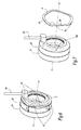
figure 3 is an exploded perspective view of the rolling bearing assembly offigures 1 and 2 ; -
figure 4 is a perspective view of a bearing, a sensor body and a preloading element belonging to the rolling bearing assembly offigures 1 to 3 ; -
figure 5 is an partially exploded view of the bearing, the sensor body and the preloading element offigure 4 ; -
figures 6 and 7 are view similar tofigures 4 and 5 , for a rolling bearing assembly according to a second embodiment of the invention. - The rolling bearing assembly A represented on
figure 1 is adapted to be mounted on an automotive vehicle, such as a motorcycle. The rolling bearing assembly A comprises a shaft C, a housing H and a sensor bearing unit U. - The rolling bearing assembly A defines a central rotation axis X-X'. In this description, the words "axial" and "radial" are used in reference to axis X-X'.
- The sensor-bearing unit U comprises a rolling bearing 2 including a rotating ring 22 and a
stationary ring 24. In the example, the rotating ring 22 is the inner ring, while thestationary ring 24 is the outer ring. The rolling bearing 2 also includes rolling elements which are balls 26 in this example. - In a non-shown embodiment, the rolling bearing 2 may comprise another type of rolling elements, such as rollers or needles.
- The sensor bearing unit U comprises a sensor unit 6 which includes an
impulse ring 62 coupled in rotation to the rotating ring 22 and asensing unit 64 comprising at least onesensing element 641 mounted in asensor body 66 which is fixed to thestationary ring 24. - The
sensor body 66 comprises anaxial surface 661 against which thepre-stressing element 4 exerts the pre-stressing force F4. Thesensor body 66 transmits the pre-stressing force F4 to thestationary ring 24 thanks to anaxial portion 663 which connects theaxial surface 661 to thestationary ring 24. - The sensor-bearing unit U includes a sleeve 8 in which the bearing 2 and the
sensor body 66 are mounted. The sleeve 8 comprises acylindrical portion 80 mounted in a bore H1 of the housing H. Thecylindrical portion 80 defines an inner bore 800, against which thestationary ring 24 is mounted, the sleeve 8 thereby providing a support for thestationary ring 24. - The sleeve 8 aims at compensating the effects of thermal dilatation, which can cause the bore H1 to enlarge and provoke a clearance between the
stationary ring 24 and the housing H. - The mounting of the
sensor body 66 on the sleeve 8 facilitates the assembly of the rolling bearing assembly A. - The sleeve 8 is made of a metallic material such as steel.
- As an alternative, the sleeve 8 can be made of a synthetic material, such as polyethylene terephthalate (PET). Such a material is light, not much expensive, provides electric isolation properties and is suitable for compensating dilatation of metallic rings such as the
outer ring 24. - The housing H may also be made of a synthetic material such as PET. The housing H and the sleeve 8 may both be made of a synthetic material, or only one of the housing H and the sleeve 8 may be made of a synthetic material.
- The
sensor body 66 may be attached to the sleeve 8 by any convenient means selected amongst, for example, over molding, elastic mounting, gluing or welding. - The sensor unit 6 is adapted to transmit sensed data via wire transmission. The sensor unit 6 therefore comprises an
output transmission cable 68. In this example, thecable 68 extends in a slightly angled axial direction. As a non-shown embodiment, theoutput cable 68 may extend in a purely axial direction. - The sensor bearing unit U further includes an optional
pre-stressing element 4 for pre-stressing thestationary ring 24, adapted to exert a pre-stressing force F4 between the housing H and thestationary ring 24. In the example, thepre-stressing element 4 is a wavy spring. - The sleeve 8 comprises an inwardly extending
radial portion 82 against which thepre-stressing element 4 is in contact. Theaxial surface 661 of thesensor body 66 and theradial portion 82 of the sleeve 8 form a chamber in which thepre-stressing element 4 is mounted. Theradial portion 82 extends in acircumferential groove 665 of thesensor body 66, which defines theaxial surface 661. - The
pre-stressing element 4 comprises alternated waves 41, which are in contact withaxial surface radial portion 82. - A second embodiment of the invention is represented on
figures 6 and 7 . In this embodiment, elements similar to the first embodiment have the same references and work in the same way. Only the differences with respect to the first embodiment are described hereafter. - In this embodiment, the sensor unit 6 comprises an
output transmission cable 69 which extend in a radial direction. - According to a non-shown embodiment, the sensor bearing unit U may comprise no
pre-stressing element 4. - According to a non-shown embodiment, the sensor unit 6 is adapted to transmit sensed data via wireless transmission.
- According to another non-shown embodiment, the
sensor body 66 may be as a whole inserted axially between the bearing 2 and theradial portion 82. - In addition, technical features of the different embodiments can be, in whole or part, combined with each other to form new embodiments of the invention.
Claims (13)
- A rolling bearing assembly (A), comprising:- a bearing (2) including a rotating ring (22) and a stationary ring (24);- a sleeve (8) in which the stationary ring (24) of the bearing (2) is mounted- a housing (H) in which the sleeve (8) is mounted;- a shaft (C) with which the rotating ring (22) of the bearing (2) is coupled in rotation with respect to the housing (H);- a sensor unit (6) including an impulse ring (62) coupled in rotation to the rotating ring (22) and a sensing unit (64) comprising at least one sensing element (641) mounted in a sensor body (66),wherein the sleeve (8), on the one hand, supports both the stationary ring (24) of the bearing (2) and the sensor body (66) and, on the other hand, compensates thermal dilatations between the housing (H) and the stationary ring (24).
- Rolling bearing assembly according to claim 1, wherein the sensor body (66) is mounted axially between the bearing (2) and a radially extending portion (82) of the sleeve (8).
- Rolling bearing assembly according to claim 1, wherein the sensor body (66) comprises a peripheral groove (665) in which an inwardly extending radial portion (82) of the sleeve (8) is received.
- Rolling bearing assembly according to any preceding claim, wherein it comprises a pre-stressing element (4) for pre-stressing the stationary ring (24), adapted to exert a pre-stressing force (F4) between the housing (H) and the stationary ring (24).
- Rolling bearing assembly according to claim 4, wherein the pre-stressing element is mounted in a chamber (10) extending between an axial surface (661) of the sensor body (66) and a radial portion (82) of the sleeve (8).
- Rolling bearing assembly according to claim 5, wherein the pre-stressing element (4) is a wavy spring.
- Rolling bearing assembly according to one of the previous claims, wherein the sensor body (66) is attached to the sleeve (8) by means selected amongst over molding, elastic mounting, gluing or welding.
- Rolling bearing assembly according to any one of the previous claims, wherein the sensor unit (6) is adapted to transmit sensed data via wire transmission.
- Rolling bearing assembly according to claim 8, wherein the sensor unit (6) comprises an axial transmission cable output (68).
- Rolling bearing assembly according to claim 8, wherein the sensor unit (6) comprises a radial transmission cable output (69).
- Rolling bearing assembly according to any one of the previous claims, wherein the sensor unit (6) is adapted to transmit sensed data via wireless transmission.
- Rolling bearing assembly according to one of the previous claims, wherein the housing (H) and/or the sleeve (8) are made of a synthetic material.
- Rolling bearing assembly according to claim 12, wherein the housing (H) and/or the sleeve (8) are made of polyethylene terephthalate.
Priority Applications (3)
| Application Number | Priority Date | Filing Date | Title |
|---|---|---|---|
| EP14306915.1A EP3026283B1 (en) | 2014-11-28 | 2014-11-28 | Rolling bearing assembly |
| US14/951,492 US20160153498A1 (en) | 2014-11-28 | 2015-11-25 | Rolling bearing assembly |
| CN201510846997.7A CN105650131A (en) | 2014-11-28 | 2015-11-27 | Rolling bearing assembly |
Applications Claiming Priority (1)
| Application Number | Priority Date | Filing Date | Title |
|---|---|---|---|
| EP14306915.1A EP3026283B1 (en) | 2014-11-28 | 2014-11-28 | Rolling bearing assembly |
Publications (2)
| Publication Number | Publication Date |
|---|---|
| EP3026283A1 true EP3026283A1 (en) | 2016-06-01 |
| EP3026283B1 EP3026283B1 (en) | 2017-08-02 |
Family
ID=52023428
Family Applications (1)
| Application Number | Title | Priority Date | Filing Date |
|---|---|---|---|
| EP14306915.1A Not-in-force EP3026283B1 (en) | 2014-11-28 | 2014-11-28 | Rolling bearing assembly |
Country Status (3)
| Country | Link |
|---|---|
| US (1) | US20160153498A1 (en) |
| EP (1) | EP3026283B1 (en) |
| CN (1) | CN105650131A (en) |
Cited By (1)
| Publication number | Priority date | Publication date | Assignee | Title |
|---|---|---|---|---|
| US11187265B2 (en) * | 2019-09-25 | 2021-11-30 | Dr. Ing. H.C. F. Porsche Aktiengesellschaft | Rolling bearing having a sensor and drive unit |
Families Citing this family (1)
| Publication number | Priority date | Publication date | Assignee | Title |
|---|---|---|---|---|
| US11821467B2 (en) * | 2021-05-17 | 2023-11-21 | Aktiebolaget Skf | Sensor bearing unit |
Citations (3)
| Publication number | Priority date | Publication date | Assignee | Title |
|---|---|---|---|---|
| FR2826413A1 (en) * | 2001-06-20 | 2002-12-27 | Skf Ab | INSTRUMENT BEARING |
| WO2010139677A1 (en) * | 2009-06-02 | 2010-12-09 | Aktiebolaget Skf | An instrumented bearing, a bearing assembly, and a rotary electrical machine including such a bearing or such an assembly |
| JP2011151978A (en) * | 2010-01-22 | 2011-08-04 | Jtekt Corp | Fixing structure of resolver sensor |
-
2014
- 2014-11-28 EP EP14306915.1A patent/EP3026283B1/en not_active Not-in-force
-
2015
- 2015-11-25 US US14/951,492 patent/US20160153498A1/en not_active Abandoned
- 2015-11-27 CN CN201510846997.7A patent/CN105650131A/en active Pending
Patent Citations (3)
| Publication number | Priority date | Publication date | Assignee | Title |
|---|---|---|---|---|
| FR2826413A1 (en) * | 2001-06-20 | 2002-12-27 | Skf Ab | INSTRUMENT BEARING |
| WO2010139677A1 (en) * | 2009-06-02 | 2010-12-09 | Aktiebolaget Skf | An instrumented bearing, a bearing assembly, and a rotary electrical machine including such a bearing or such an assembly |
| JP2011151978A (en) * | 2010-01-22 | 2011-08-04 | Jtekt Corp | Fixing structure of resolver sensor |
Cited By (1)
| Publication number | Priority date | Publication date | Assignee | Title |
|---|---|---|---|---|
| US11187265B2 (en) * | 2019-09-25 | 2021-11-30 | Dr. Ing. H.C. F. Porsche Aktiengesellschaft | Rolling bearing having a sensor and drive unit |
Also Published As
| Publication number | Publication date |
|---|---|
| US20160153498A1 (en) | 2016-06-02 |
| EP3026283B1 (en) | 2017-08-02 |
| CN105650131A (en) | 2016-06-08 |
Similar Documents
| Publication | Publication Date | Title |
|---|---|---|
| US9226441B2 (en) | Hub-bearing assembly | |
| US20190211876A1 (en) | Wheel bearing sealing device and manufacturing method therefor | |
| EP1237004A3 (en) | Rolling bearing unit with rotational speed sensor | |
| US20170239989A1 (en) | Axle assembly with outboard axle bearings | |
| US20160319922A1 (en) | Rotary transmitting assembly, device for converting rotary motion to linear motion, and motor | |
| US9194423B2 (en) | Rolling bearing device, in particular for a steering column | |
| CN105317847B (en) | Inserts, seals, universal joints and bearing bushes for rolling bearing seals | |
| US9266556B2 (en) | Rack guide unit and steering system including the rack guide unit | |
| US20160153498A1 (en) | Rolling bearing assembly | |
| US20180156280A1 (en) | Rotary machine | |
| US20220212532A1 (en) | Conical mount with rotating radial snubber assembly | |
| JP2017015426A5 (en) | ||
| WO2016082893A1 (en) | Sensor bearing unit and rolling bearing assembly comprising such a unit | |
| WO2016188556A1 (en) | Shaft supporting system for an electric motor, electric motor comprising such a system and process for assembling such a shaft supporting system | |
| EP2975278B1 (en) | Rolling bearing and method for manufacturing such a rolling bearing | |
| WO2016192752A1 (en) | Rolling bearing assembly with pre-stressing element and sensor unit | |
| WO2011135209A3 (en) | Instrumented assembly for an axle journal | |
| KR101383270B1 (en) | Taper roller bearing | |
| CN110017326A (en) | Bearing assembly | |
| EP3199419B1 (en) | Railway axlebox bearing assembly with mounting surface | |
| US7032470B2 (en) | Yoke bearing providing improved support | |
| WO2011018320A3 (en) | Rolling bearing arrangement for a motor vehicle transmission, having lubricant supply via recesses in the two end faces of the inner ring | |
| WO2011161492A1 (en) | Friction device for a bearing assembly, bearing and bearing assembly comprising such a friction device | |
| EP1759882A3 (en) | Wheel hub rolling element bearing assembly with sealing arrangement | |
| CN108688799A (en) | Roller pinion gear for driving aircraft wheel to rotate |
Legal Events
| Date | Code | Title | Description |
|---|---|---|---|
| PUAI | Public reference made under article 153(3) epc to a published international application that has entered the european phase |
Free format text: ORIGINAL CODE: 0009012 |
|
| AK | Designated contracting states |
Kind code of ref document: A1 Designated state(s): AL AT BE BG CH CY CZ DE DK EE ES FI FR GB GR HR HU IE IS IT LI LT LU LV MC MK MT NL NO PL PT RO RS SE SI SK SM TR |
|
| AX | Request for extension of the european patent |
Extension state: BA ME |
|
| 17P | Request for examination filed |
Effective date: 20161118 |
|
| RBV | Designated contracting states (corrected) |
Designated state(s): AL AT BE BG CH CY CZ DE DK EE ES FI FR GB GR HR HU IE IS IT LI LT LU LV MC MK MT NL NO PL PT RO RS SE SI SK SM TR |
|
| GRAP | Despatch of communication of intention to grant a patent |
Free format text: ORIGINAL CODE: EPIDOSNIGR1 |
|
| INTG | Intention to grant announced |
Effective date: 20170220 |
|
| GRAS | Grant fee paid |
Free format text: ORIGINAL CODE: EPIDOSNIGR3 |
|
| GRAA | (expected) grant |
Free format text: ORIGINAL CODE: 0009210 |
|
| AK | Designated contracting states |
Kind code of ref document: B1 Designated state(s): AL AT BE BG CH CY CZ DE DK EE ES FI FR GB GR HR HU IE IS IT LI LT LU LV MC MK MT NL NO PL PT RO RS SE SI SK SM TR |
|
| REG | Reference to a national code |
Ref country code: CH Ref legal event code: EP Ref country code: AT Ref legal event code: REF Ref document number: 914830 Country of ref document: AT Kind code of ref document: T Effective date: 20170815 |
|
| REG | Reference to a national code |
Ref country code: IE Ref legal event code: FG4D |
|
| REG | Reference to a national code |
Ref country code: DE Ref legal event code: R096 Ref document number: 602014012488 Country of ref document: DE |
|
| REG | Reference to a national code |
Ref country code: NL Ref legal event code: MP Effective date: 20170802 |
|
| REG | Reference to a national code |
Ref country code: AT Ref legal event code: MK05 Ref document number: 914830 Country of ref document: AT Kind code of ref document: T Effective date: 20170802 |
|
| REG | Reference to a national code |
Ref country code: LT Ref legal event code: MG4D |
|
| PG25 | Lapsed in a contracting state [announced via postgrant information from national office to epo] |
Ref country code: NO Free format text: LAPSE BECAUSE OF FAILURE TO SUBMIT A TRANSLATION OF THE DESCRIPTION OR TO PAY THE FEE WITHIN THE PRESCRIBED TIME-LIMIT Effective date: 20171102 Ref country code: HR Free format text: LAPSE BECAUSE OF FAILURE TO SUBMIT A TRANSLATION OF THE DESCRIPTION OR TO PAY THE FEE WITHIN THE PRESCRIBED TIME-LIMIT Effective date: 20170802 Ref country code: NL Free format text: LAPSE BECAUSE OF FAILURE TO SUBMIT A TRANSLATION OF THE DESCRIPTION OR TO PAY THE FEE WITHIN THE PRESCRIBED TIME-LIMIT Effective date: 20170802 Ref country code: SE Free format text: LAPSE BECAUSE OF FAILURE TO SUBMIT A TRANSLATION OF THE DESCRIPTION OR TO PAY THE FEE WITHIN THE PRESCRIBED TIME-LIMIT Effective date: 20170802 Ref country code: AT Free format text: LAPSE BECAUSE OF FAILURE TO SUBMIT A TRANSLATION OF THE DESCRIPTION OR TO PAY THE FEE WITHIN THE PRESCRIBED TIME-LIMIT Effective date: 20170802 Ref country code: LT Free format text: LAPSE BECAUSE OF FAILURE TO SUBMIT A TRANSLATION OF THE DESCRIPTION OR TO PAY THE FEE WITHIN THE PRESCRIBED TIME-LIMIT Effective date: 20170802 Ref country code: FI Free format text: LAPSE BECAUSE OF FAILURE TO SUBMIT A TRANSLATION OF THE DESCRIPTION OR TO PAY THE FEE WITHIN THE PRESCRIBED TIME-LIMIT Effective date: 20170802 |
|
| PG25 | Lapsed in a contracting state [announced via postgrant information from national office to epo] |
Ref country code: LV Free format text: LAPSE BECAUSE OF FAILURE TO SUBMIT A TRANSLATION OF THE DESCRIPTION OR TO PAY THE FEE WITHIN THE PRESCRIBED TIME-LIMIT Effective date: 20170802 Ref country code: RS Free format text: LAPSE BECAUSE OF FAILURE TO SUBMIT A TRANSLATION OF THE DESCRIPTION OR TO PAY THE FEE WITHIN THE PRESCRIBED TIME-LIMIT Effective date: 20170802 Ref country code: PL Free format text: LAPSE BECAUSE OF FAILURE TO SUBMIT A TRANSLATION OF THE DESCRIPTION OR TO PAY THE FEE WITHIN THE PRESCRIBED TIME-LIMIT Effective date: 20170802 Ref country code: ES Free format text: LAPSE BECAUSE OF FAILURE TO SUBMIT A TRANSLATION OF THE DESCRIPTION OR TO PAY THE FEE WITHIN THE PRESCRIBED TIME-LIMIT Effective date: 20170802 Ref country code: BG Free format text: LAPSE BECAUSE OF FAILURE TO SUBMIT A TRANSLATION OF THE DESCRIPTION OR TO PAY THE FEE WITHIN THE PRESCRIBED TIME-LIMIT Effective date: 20171102 Ref country code: GR Free format text: LAPSE BECAUSE OF FAILURE TO SUBMIT A TRANSLATION OF THE DESCRIPTION OR TO PAY THE FEE WITHIN THE PRESCRIBED TIME-LIMIT Effective date: 20171103 Ref country code: IS Free format text: LAPSE BECAUSE OF FAILURE TO SUBMIT A TRANSLATION OF THE DESCRIPTION OR TO PAY THE FEE WITHIN THE PRESCRIBED TIME-LIMIT Effective date: 20171202 |
|
| PG25 | Lapsed in a contracting state [announced via postgrant information from national office to epo] |
Ref country code: RO Free format text: LAPSE BECAUSE OF FAILURE TO SUBMIT A TRANSLATION OF THE DESCRIPTION OR TO PAY THE FEE WITHIN THE PRESCRIBED TIME-LIMIT Effective date: 20170802 Ref country code: CZ Free format text: LAPSE BECAUSE OF FAILURE TO SUBMIT A TRANSLATION OF THE DESCRIPTION OR TO PAY THE FEE WITHIN THE PRESCRIBED TIME-LIMIT Effective date: 20170802 Ref country code: DK Free format text: LAPSE BECAUSE OF FAILURE TO SUBMIT A TRANSLATION OF THE DESCRIPTION OR TO PAY THE FEE WITHIN THE PRESCRIBED TIME-LIMIT Effective date: 20170802 |
|
| REG | Reference to a national code |
Ref country code: DE Ref legal event code: R097 Ref document number: 602014012488 Country of ref document: DE |
|
| PG25 | Lapsed in a contracting state [announced via postgrant information from national office to epo] |
Ref country code: SK Free format text: LAPSE BECAUSE OF FAILURE TO SUBMIT A TRANSLATION OF THE DESCRIPTION OR TO PAY THE FEE WITHIN THE PRESCRIBED TIME-LIMIT Effective date: 20170802 Ref country code: EE Free format text: LAPSE BECAUSE OF FAILURE TO SUBMIT A TRANSLATION OF THE DESCRIPTION OR TO PAY THE FEE WITHIN THE PRESCRIBED TIME-LIMIT Effective date: 20170802 Ref country code: SM Free format text: LAPSE BECAUSE OF FAILURE TO SUBMIT A TRANSLATION OF THE DESCRIPTION OR TO PAY THE FEE WITHIN THE PRESCRIBED TIME-LIMIT Effective date: 20170802 Ref country code: IT Free format text: LAPSE BECAUSE OF FAILURE TO SUBMIT A TRANSLATION OF THE DESCRIPTION OR TO PAY THE FEE WITHIN THE PRESCRIBED TIME-LIMIT Effective date: 20170802 |
|
| REG | Reference to a national code |
Ref country code: DE Ref legal event code: R119 Ref document number: 602014012488 Country of ref document: DE |
|
| PLBE | No opposition filed within time limit |
Free format text: ORIGINAL CODE: 0009261 |
|
| STAA | Information on the status of an ep patent application or granted ep patent |
Free format text: STATUS: NO OPPOSITION FILED WITHIN TIME LIMIT |
|
| PG25 | Lapsed in a contracting state [announced via postgrant information from national office to epo] |
Ref country code: MC Free format text: LAPSE BECAUSE OF FAILURE TO SUBMIT A TRANSLATION OF THE DESCRIPTION OR TO PAY THE FEE WITHIN THE PRESCRIBED TIME-LIMIT Effective date: 20170802 |
|
| 26N | No opposition filed |
Effective date: 20180503 |
|
| PG25 | Lapsed in a contracting state [announced via postgrant information from national office to epo] |
Ref country code: LI Free format text: LAPSE BECAUSE OF NON-PAYMENT OF DUE FEES Effective date: 20171130 Ref country code: CH Free format text: LAPSE BECAUSE OF NON-PAYMENT OF DUE FEES Effective date: 20171130 |
|
| PG25 | Lapsed in a contracting state [announced via postgrant information from national office to epo] |
Ref country code: LU Free format text: LAPSE BECAUSE OF NON-PAYMENT OF DUE FEES Effective date: 20171128 Ref country code: SI Free format text: LAPSE BECAUSE OF FAILURE TO SUBMIT A TRANSLATION OF THE DESCRIPTION OR TO PAY THE FEE WITHIN THE PRESCRIBED TIME-LIMIT Effective date: 20170802 |
|
| REG | Reference to a national code |
Ref country code: FR Ref legal event code: ST Effective date: 20180731 Ref country code: BE Ref legal event code: MM Effective date: 20171130 |
|
| REG | Reference to a national code |
Ref country code: IE Ref legal event code: MM4A |
|
| PG25 | Lapsed in a contracting state [announced via postgrant information from national office to epo] |
Ref country code: MT Free format text: LAPSE BECAUSE OF NON-PAYMENT OF DUE FEES Effective date: 20171128 |
|
| PG25 | Lapsed in a contracting state [announced via postgrant information from national office to epo] |
Ref country code: DE Free format text: LAPSE BECAUSE OF NON-PAYMENT OF DUE FEES Effective date: 20180602 Ref country code: FR Free format text: LAPSE BECAUSE OF NON-PAYMENT OF DUE FEES Effective date: 20171130 Ref country code: IE Free format text: LAPSE BECAUSE OF NON-PAYMENT OF DUE FEES Effective date: 20171128 |
|
| PG25 | Lapsed in a contracting state [announced via postgrant information from national office to epo] |
Ref country code: BE Free format text: LAPSE BECAUSE OF NON-PAYMENT OF DUE FEES Effective date: 20171130 |
|
| PG25 | Lapsed in a contracting state [announced via postgrant information from national office to epo] |
Ref country code: HU Free format text: LAPSE BECAUSE OF FAILURE TO SUBMIT A TRANSLATION OF THE DESCRIPTION OR TO PAY THE FEE WITHIN THE PRESCRIBED TIME-LIMIT; INVALID AB INITIO Effective date: 20141128 |
|
| GBPC | Gb: european patent ceased through non-payment of renewal fee |
Effective date: 20181128 |
|
| PG25 | Lapsed in a contracting state [announced via postgrant information from national office to epo] |
Ref country code: CY Free format text: LAPSE BECAUSE OF FAILURE TO SUBMIT A TRANSLATION OF THE DESCRIPTION OR TO PAY THE FEE WITHIN THE PRESCRIBED TIME-LIMIT Effective date: 20170802 |
|
| PG25 | Lapsed in a contracting state [announced via postgrant information from national office to epo] |
Ref country code: MK Free format text: LAPSE BECAUSE OF FAILURE TO SUBMIT A TRANSLATION OF THE DESCRIPTION OR TO PAY THE FEE WITHIN THE PRESCRIBED TIME-LIMIT Effective date: 20170802 |
|
| PG25 | Lapsed in a contracting state [announced via postgrant information from national office to epo] |
Ref country code: GB Free format text: LAPSE BECAUSE OF NON-PAYMENT OF DUE FEES Effective date: 20181128 |
|
| PG25 | Lapsed in a contracting state [announced via postgrant information from national office to epo] |
Ref country code: TR Free format text: LAPSE BECAUSE OF FAILURE TO SUBMIT A TRANSLATION OF THE DESCRIPTION OR TO PAY THE FEE WITHIN THE PRESCRIBED TIME-LIMIT Effective date: 20170802 |
|
| PG25 | Lapsed in a contracting state [announced via postgrant information from national office to epo] |
Ref country code: PT Free format text: LAPSE BECAUSE OF FAILURE TO SUBMIT A TRANSLATION OF THE DESCRIPTION OR TO PAY THE FEE WITHIN THE PRESCRIBED TIME-LIMIT Effective date: 20170802 |
|
| PG25 | Lapsed in a contracting state [announced via postgrant information from national office to epo] |
Ref country code: AL Free format text: LAPSE BECAUSE OF FAILURE TO SUBMIT A TRANSLATION OF THE DESCRIPTION OR TO PAY THE FEE WITHIN THE PRESCRIBED TIME-LIMIT Effective date: 20170802 |