EP3026264A1 - Variable displacement swash-plate compressor - Google Patents
Variable displacement swash-plate compressor Download PDFInfo
- Publication number
- EP3026264A1 EP3026264A1 EP15195803.0A EP15195803A EP3026264A1 EP 3026264 A1 EP3026264 A1 EP 3026264A1 EP 15195803 A EP15195803 A EP 15195803A EP 3026264 A1 EP3026264 A1 EP 3026264A1
- Authority
- EP
- European Patent Office
- Prior art keywords
- drive shaft
- swash plate
- acting
- movable body
- shaft axis
- Prior art date
- Legal status (The legal status is an assumption and is not a legal conclusion. Google has not performed a legal analysis and makes no representation as to the accuracy of the status listed.)
- Granted
Links
Images


Classifications
-
- F—MECHANICAL ENGINEERING; LIGHTING; HEATING; WEAPONS; BLASTING
- F04—POSITIVE - DISPLACEMENT MACHINES FOR LIQUIDS; PUMPS FOR LIQUIDS OR ELASTIC FLUIDS
- F04B—POSITIVE-DISPLACEMENT MACHINES FOR LIQUIDS; PUMPS
- F04B27/00—Multi-cylinder pumps specially adapted for elastic fluids and characterised by number or arrangement of cylinders
- F04B27/08—Multi-cylinder pumps specially adapted for elastic fluids and characterised by number or arrangement of cylinders having cylinders coaxial with, or parallel or inclined to, main shaft axis
- F04B27/14—Control
-
- F—MECHANICAL ENGINEERING; LIGHTING; HEATING; WEAPONS; BLASTING
- F04—POSITIVE - DISPLACEMENT MACHINES FOR LIQUIDS; PUMPS FOR LIQUIDS OR ELASTIC FLUIDS
- F04B—POSITIVE-DISPLACEMENT MACHINES FOR LIQUIDS; PUMPS
- F04B27/00—Multi-cylinder pumps specially adapted for elastic fluids and characterised by number or arrangement of cylinders
- F04B27/08—Multi-cylinder pumps specially adapted for elastic fluids and characterised by number or arrangement of cylinders having cylinders coaxial with, or parallel or inclined to, main shaft axis
- F04B27/10—Multi-cylinder pumps specially adapted for elastic fluids and characterised by number or arrangement of cylinders having cylinders coaxial with, or parallel or inclined to, main shaft axis having stationary cylinders
- F04B27/1036—Component parts, details, e.g. sealings, lubrication
- F04B27/1054—Actuating elements
-
- F—MECHANICAL ENGINEERING; LIGHTING; HEATING; WEAPONS; BLASTING
- F04—POSITIVE - DISPLACEMENT MACHINES FOR LIQUIDS; PUMPS FOR LIQUIDS OR ELASTIC FLUIDS
- F04B—POSITIVE-DISPLACEMENT MACHINES FOR LIQUIDS; PUMPS
- F04B27/00—Multi-cylinder pumps specially adapted for elastic fluids and characterised by number or arrangement of cylinders
- F04B27/08—Multi-cylinder pumps specially adapted for elastic fluids and characterised by number or arrangement of cylinders having cylinders coaxial with, or parallel or inclined to, main shaft axis
- F04B27/0873—Component parts, e.g. sealings; Manufacturing or assembly thereof
- F04B27/0895—Component parts, e.g. sealings; Manufacturing or assembly thereof driving means
-
- F—MECHANICAL ENGINEERING; LIGHTING; HEATING; WEAPONS; BLASTING
- F04—POSITIVE - DISPLACEMENT MACHINES FOR LIQUIDS; PUMPS FOR LIQUIDS OR ELASTIC FLUIDS
- F04B—POSITIVE-DISPLACEMENT MACHINES FOR LIQUIDS; PUMPS
- F04B27/00—Multi-cylinder pumps specially adapted for elastic fluids and characterised by number or arrangement of cylinders
- F04B27/08—Multi-cylinder pumps specially adapted for elastic fluids and characterised by number or arrangement of cylinders having cylinders coaxial with, or parallel or inclined to, main shaft axis
- F04B27/10—Multi-cylinder pumps specially adapted for elastic fluids and characterised by number or arrangement of cylinders having cylinders coaxial with, or parallel or inclined to, main shaft axis having stationary cylinders
- F04B27/1036—Component parts, details, e.g. sealings, lubrication
- F04B27/1054—Actuating elements
- F04B27/1072—Pivot mechanisms
-
- F—MECHANICAL ENGINEERING; LIGHTING; HEATING; WEAPONS; BLASTING
- F04—POSITIVE - DISPLACEMENT MACHINES FOR LIQUIDS; PUMPS FOR LIQUIDS OR ELASTIC FLUIDS
- F04B—POSITIVE-DISPLACEMENT MACHINES FOR LIQUIDS; PUMPS
- F04B27/00—Multi-cylinder pumps specially adapted for elastic fluids and characterised by number or arrangement of cylinders
- F04B27/08—Multi-cylinder pumps specially adapted for elastic fluids and characterised by number or arrangement of cylinders having cylinders coaxial with, or parallel or inclined to, main shaft axis
- F04B27/14—Control
- F04B27/16—Control of pumps with stationary cylinders
- F04B27/18—Control of pumps with stationary cylinders by varying the relative positions of a swash plate and a cylinder block
Definitions
- the present invention relates to a variable displacement swash-plate compressor.
- Japanese Laid-Open Patent Publication No. 52-131204 discloses a conventional variable displacement swash-plate compressor (hereinafter, referred to as a compressor).
- the compressor includes a swash plate chamber, cylinder bores, a suction chamber, and a discharge chamber, which are provided in the housing.
- a drive shaft is rotationally supported in the housing.
- the swash plate chamber accommodates a swash plate, which is rotational through rotation of the drive shaft.
- the swash plate has a through hole.
- a link mechanism is located between the drive shaft and the swash plate. The link mechanism allows the inclination angle of the swash plate to be changed.
- the inclination angle is the angle of the swash plate in relation to a direction perpendicular to the axis of the drive shaft.
- Each cylinder bore reciprocally accommodates a piston.
- a conversion mechanism reciprocates each of the pistons in the associated one of the cylinder bores by the stroke corresponding to the inclination angle through rotation of the swash plate.
- Atop dead center associated part for positioning each piston at the top dead center is defined on the swash plate.
- the inclination angle of the swash plate is changed by an actuator.
- the actuator is controlled by a control mechanism.
- the control mechanism includes a pressure regulation valve.
- the link mechanism includes a lug member, a hinge ball, and a link.
- the lug member is located in the swash plate chamber and is fixed to the drive shaft.
- the hinge ball is fitted about the drive shaft to be arranged in the through hole of the swash plate. This causes the outer circumferential surface of the hinge ball to contact the through hole.
- the link is provided between the lug member and the swash plate. The link connects the swash plate to the lug member, so that the swash plate is permitted to pivot.
- the actuator includes the lug member, a movable body, and a control pressure chamber.
- the movable body has a cylindrical shape.
- the movable body is fitted about the drive shaft to be arranged between the lug member and the hinge ball.
- the movable body and the hinge ball contact each other, the movable body is engaged with the swash plate via the hinge ball.
- the movable body changes the inclination angle of the swash plate.
- the control pressure chamber which is defined by the lug member and the movable body, uses its internal pressure to move the movable body.
- the movable body of the actuator and the swash plate are engaged with each other via the hinge ball.
- the size of the entire compressor needs to be increased to increase the size of the movable body so that the movable body is easily moved with a great thrust.
- the movable body When decreasing the inclination angle of the swash plate in the compressor, the movable body pushes the swash plate via the hinge ball.
- the tolerance during manufacture is likely to vary contacting positions between the outer circumferential surface of the hinge ball and the swash plate. Accordingly, when the movable body pushes the hinge ball, the direction of the load acting on the swash plate is likely to change. Thus, the movable body cannot smoothly move the hinge ball along the axis of the drive shaft, and the movable body cannot stably decrease the inclination angle of the swash plate.
- the orientation of the movable body tends to be unstable, which can result in pressure leakage in the control pressure chamber. In this case, the displacement cannot be quickly changed in response to changes in the driving state of machinery on which the compressor is mounted, such as a vehicle, and high controllability cannot be achieved.
- An objective of the present invention is to provide a variable displacement swash-plate compressor that achieves a sufficient controllability while minimizing the size.
- a variable displacement swash-plate compressor that includes a housing having a swash plate chamber and a cylinder bore, a drive shaft that is rotationally supported by the housing, a swash plate that is supported in the swash plate chamber and is rotational by rotation of the drive shaft, a link mechanism, a piston, a conversion mechanism, an actuator, and a control mechanism.
- the link mechanism is arranged between the drive shaft and the swash plate, and allows an inclination angle of the swash plate to be changed with respect to a direction perpendicular to a drive shaft axis of the drive shaft.
- the piston is reciprocally received in the cylinder bore.
- the conversion mechanism causes the piston to reciprocate in the cylinder bore by a stroke corresponding to the inclination angle of the swash plate through rotation of the swash plate.
- the actuator is configured to change the inclination angle.
- the control mechanism controls the actuator.
- the link mechanism includes a lug member that is located in the swash plate chamber and is fixed to the drive shaft and a transmitting member that transmits rotation of the lug member to the swash plate.
- the swash plate has a through hole, which slides on an outer circumference of the drive shaft in response to changes in the inclination angle. The swash plate is guided by the link mechanism and the through hole along the drive shaft axis and in a direction of the inclination angle, thereby changing the inclination angle.
- the actuator includes the lug member, a movable body, and a control pressure chamber.
- the movable body is located between the lug member and the swash plate and is configured to rotate integrally with the swash plate and to move along the drive shaft axis, thereby changing the inclination angle.
- the control pressure chamber is defined by the lug member and the movable body and is configured such that pressure in the control pressure chamber is changed by the control mechanism to move the movable body.
- the movable body includes an acting portion that is configured to push the swash plate with the pressure in the control pressure chamber.
- the swash plate includes a receiving portion that contacts and is pushed by the acting portion. The acting portion and the receiving portion contact each other at an acting position.
- Atop dead center associated part for positioning the piston at a top dead center is defined on the swash plate.
- the acting position is defined at a position overlapping with the drive shaft regardless of the inclination angle.
- Compressors according to the first to third embodiments are variable displacement swash-plate compressors with single-headed pistons. These compressors are installed in vehicles and are each included in the refrigeration circuit in the air conditioner for the vehicle.
- the compressor according to the first embodiment includes a housing 1, a drive shaft 3, a swash plate 5, a link mechanism 7, pistons 9, pairs of shoes 11a, 11b, an actuator 13, and a control mechanism 15, which is illustrated in Fig. 2 .
- the housing 1 has a front housing member 17 at a front position in the compressor, a rear housing member 19 at a rear position in the compressor, and a cylinder block 21 and a valve assembly plate 23, which are arranged between the front housing member 17 and the rear housing member 19.
- the front housing member 17 includes a front wall 17a, which extends in the vertical direction of the compressor on the front side, and a circumferential wall 17b, which is integrated with the front wall 17a and extends rearward from the front of the compressor.
- the front housing member 17 has a substantially cylindrical cup shape with the front wall 17a and the circumferential wall 17b. Furthermore, the front wall 17a and the circumferential wall 17b define a swash plate chamber 25 in the front housing member 17.
- the front wall 17a has a boss 17c, which projects forward.
- the boss 17c accommodates a shaft sealing device 27.
- the boss 17c has a first shaft hole 17d, which extends in the front-rear direction of the compressor.
- the first shaft hole 17d accommodates a first slide bearing 29a.
- the circumferential wall 17b has an inlet 250, which communicates with the swash plate chamber 25.
- the swash plate chamber 25 is connected to a non-illustrated evaporator through the inlet 250. Since low-pressure refrigerant gas that has passed through the evaporator flows into the swash plate chamber 25 via the inlet 250, the pressures in the swash plate chamber 25 is lower than the pressure in a discharge chamber 35, which will be discussed below.
- the rear housing member 19 includes a first pressure regulation chamber 31a, a suction chamber 33, and the discharge chamber 35.
- the first pressure regulation chamber 31a is located in the central part of the rear housing member 19.
- the discharge chamber 35 has an annular shape and is located in a radially outer part of the rear housing member 19.
- the suction chamber 33 has an annular shape between the first pressure regulation chamber 31a and the discharge chamber 35 in the rear housing member 19.
- the discharge chamber 35 is connected to a non-illustrated outlet.
- the cylinder block 21 includes cylinder bores 21a, the number of which is the same as that of the pistons 9.
- the cylinder bores 21a are arranged at equal angular intervals in the circumferential direction.
- the front end of the each cylinder bore 21a communicates with the swash plate chamber 25.
- the cylinder block 21 also includes retainer grooves 21 b, which limit the lift of suction reed valves 41a, which will be discussed below.
- the cylinder block 21 further includes a second shaft hole 21c, which communicates with the swash plate chamber 25 and extends in the front-rear direction of the compressor.
- the second shaft hole 21c accommodates a second slide bearing 29b.
- the first slide bearing 29a and the second slide bearing 29b may be replaced by rolling-element bearings.
- the cylinder block 21 further has a spring chamber 21d.
- the spring chamber 21d is located between the swash plate chamber 25 and the second shaft hole 21c.
- the spring chamber 21d accommodates a restoration spring 37.
- the restoration spring 37 urges the swash plate 5 forward of the swash plate chamber 25 when the inclination angle is minimized.
- the cylinder block 21 also includes a suction passage 39, which communicates with the swash plate chamber 25.
- the valve assembly plate 23 is located between the rear housing member 19 and the cylinder block 21.
- the valve assembly plate 23 includes a valve base plate 40, a suction valve plate 41, a discharge valve plate 43, and a retainer plate 45.
- the valve base plate 40, the discharge valve plate 43, and the retainer plate 45 include suction ports 40a, the number of which is equal to that of the cylinder bores 21 a. Furthermore, the valve base plate 40 and the suction valve plate 41 include discharge ports 40b, the number of which is equal to that of the cylinder bores 21a.
- the cylinder bores 21a communicate with the suction chamber 33 through the suction ports 40a and communicate with the discharge chamber 35 through the discharge ports 40b.
- the valve base plate 40, the suction valve plate 41, the discharge valve plate 43, and the retainer plate 45 include a first communication hole 40c and a second communication hole 40d.
- the first communication hole 40c connects the suction chamber 33 to the suction passage 39. This causes the swash plate chamber 25 to communicate with the suction chamber 33.
- the suction valve plate 41 is provided on the front surface of the valve base plate 40.
- the suction valve plate 41 includes suction reed valves 41a, which are allowed to selectively open and close the suction ports 40a by elastic deformation.
- the discharge valve plate 43 is located on the rear surface of the valve base plate 40.
- the discharge valve plate 43 includes discharge reed valves 43a, which are allowed to selectively open and close the discharge ports 40b by elastic deformation.
- the retainer plate 45 is provided on the rear surface of the discharge valve plate 43. The retainer plate 45 limits the maximum opening degree of the discharge reed valves 43a.
- the drive shaft 3 has a cylindrical outer circumferential surface 30.
- the drive shaft 3 is inserted in the boss 17c toward the rear of the housing 1.
- the front portion of the drive shaft 3 is supported by the shaft sealing device 27 in the boss 17c and is supported by the first slide bearing 29a in the first shaft hole 17d.
- the rear portion of the drive shaft 3 is supported by the second slide bearing 29b in the second shaft hole 21c.
- the second shaft hole 21c and the rear end of the drive shaft 3 define a second pressure regulation chamber 31 b.
- the second pressure regulation chamber 31 b communicates with the first pressure regulation chamber 31a through the second communication hole 40d.
- the first and second pressure regulation chambers 31a, 31b constitute a pressure regulation chamber 31.
- O-rings 49a, 49b are provided on the rear end of the drive shaft 3.
- the O-rings 49a, 49b are located between the drive shaft 3 and the second shaft hole 21c to seal off the swash plate chamber 25 and the pressure regulation chamber 31 from each other.
- the link mechanism 7, the swash plate 5, and the actuator 13 are mounted on the drive shaft 3.
- the link mechanism 7 includes first and second swash plate arms 5e, 5f provided on the swash plate 5 shown in Fig. 3 , a lug plate 51 shown in Fig. 4 , and first and second lug arms 53a, 53b provided on the lug plate 51.
- the first and second swash plate arms 5e, 5f correspond to transmitting members.
- the lug plate 51 corresponds to a lug member.
- part of the second swash plate arm 5f is omitted by using a break line.
- the swash plate 5 has a swash plate main portion 50, a swash plate weight 5c, and the first and second swash plate arms 5e, 5f.
- the swash plate main portion 50 is shaped as a flat annular plate and has a front surface 5a and a rear surface 5b.
- Atop dead center associated part T for positioning each piston 9 at the top dead center and a bottom dead center associated part U for positioning each piston 9 at the bottom dead center are defined on the swash plate main portion 50.
- an imaginary top dead center plane D is defined in this compressor.
- the top dead center plane D includes the top dead center associated part T, the bottom dead center associated part U, and the drive shaft axis O. Further, as shown in Fig.
- the swash plate main portion 50 includes an imaginary swash plate reference plane S for determining the inclination angle of the swash plate 5 in relation to a direction perpendicular to the drive shaft axis O.
- the swash plate reference plane S is parallel with the front surface 5a and the rear surface 5b.
- the swash plate main portion 50 includes a through hole 5d.
- the drive shaft 3 is inserted in the through hole 5d.
- Two flat guide surfaces 52a, 52b are provided in the through hole 5d.
- the guide surfaces 52a, 52b contact the outer circumferential surface 30 of the drive shaft 3.
- First and second receiving surfaces 54a, 54b are provided on the front surface of the swash plate main portion 50 about the through hole 5d.
- the first and second receiving surfaces 54a, 54b each correspond to a receiving surface.
- the first receiving surface 54a is a flat surface parallel with the swash plate reference plane S.
- the second receiving surface 54b which is shown in Fig. 3 , has the same structure as the first receiving surface 54a.
- the first receiving surface 54a and the second receiving surface 54b are arranged on the front surface 5a at positions on opposite sides of the top dead center plane D.
- the first receiving surface 54a and the second receiving surface 54b are arranged on the front surface 5a at positions on opposite sides of the top dead center plane D.
- the first receiving portion 6a and the second receiving portion 6b are also located on opposite sides of the top dead center plane D. Since the first and second receiving surfaces 54a, 54b are flat, the first and second receiving portions 6a, 6b are flat.
- the swash plate weight 5c is provided on the front surface 5a at a position closer to the bottom dead center associated part U than the drive shaft axis O. That is, the swash plate weight 5c is located between the drive shaft axis O and the bottom dead center associated part U. As shown in Fig. 1 , the swash plate weight 5c has a substantially semi-circular cylindrical shape and extends from the front surface 5a toward a movable body 13a, which will be discussed below.
- the first and second swash plate arms 5e, 5f are arranged on the front surface 5a at positions closer to the top dead center associated part T than the drive shaft axis O. Specifically, the first and second swash plate arms 5e, 5f are located between the drive shaft axis O and the top dead center associated part T. The first swash plate arm 5e and the second swash plate arm 5f are arranged on the front surface 5a at positions on opposite sides of the top dead center plane D. As shown in Fig. 1 , the first and second swash plate arms 5e, 5f extend from the front surface 5a toward the lug plate 51.
- the shapes of the swash plate weight 5c and the first and second swash plate arms 5e, 5f are simplified in Fig. 3 . The same applies to Figs. 10 and 14 , which will be discussed below.
- the lug plate 51 has a substantially annular shape with a through hole 510.
- the drive shaft 3 is press-fitted in the through hole 510, so that the lug plate 51 rotates integrally with the drive shaft 3.
- a thrust bearing 55 is located between the lug plate 51 and the front wall 17a.
- the lug plate 51 has a recessed cylinder chamber 51a.
- the cylinder chamber 51a has a cylindrical shape coaxial with and extending along the drive shaft axis O.
- the cylinder chamber 51a communicates with the swash plate chamber 25 at the rear.
- the first lug arm 53a and the second lug arm 53b are provided on the lug plate 51 at positions on opposite sides of the top dead center plane D.
- the first and second lug arms 53a, 53b are located at positions closer to the top dead center associated part T on the swash plate main portion 50 than the drive shaft axis O and extend from the lug plate 51 toward the swash plate 5. That is, the first and second lug arms 53a, 53b are located between the drive shaft axis O and the top dead center associated part T on the lug plate 51.
- the lug plate 51 has first and second guide surfaces 57a, 57b between the first and second lug arms 53a, 53b.
- the first guide surface 57a and the second guide surface 57b are also located on opposite sides of the top dead center plane D. As shown in Fig. 1 , the first guide surface 57a is inclined such that the distance from the swash plate 5 gradually decreases from the outer circumference of the lug plate 51 toward the cylinder chamber 51a.
- the second guide surface 57b has the same shape as the first guide surface 57a.
- the first and second swash plate arms 5e, 5f are inserted between the first and second lug arms 53a, 53b to mount the swash plate 5 to the drive shaft 3.
- the lug plate 51 and the swash plate 5 are thus coupled to each other with the first and second swash plate arms 5e, 5f located between the first and second lug arms 53a, 53b.
- the swash plate 5 rotates with the lug plate 51 in the swash plate chamber 25.
- the swash plate 5 Since the first and second swash plate arms 5e, 5f are located between the first and second lug arms 53a, 53b, the distal end of the first swash plate arm 5e contacts the first guide surface 57a, and the distal end of the second swash plate arm 5f contacts the second guide surface 57b.
- the first and second swash plate arms 5e, 5f slide on the first and second guide surfaces 57a, 57b, respectively. Accordingly, the swash plate 5 is allowed to change its inclination angle, which is defined by the swash plate reference plane S, between the minimum inclination angle shown in Figs. 1 and 9 and the maximum inclination angle shown in Fig. 8 , while substantially maintaining the position of the top dead center associated part T.
- the actuator 13 includes the lug plate 51, a movable body 13a, and a control pressure chamber 13b.
- the movable body 13a is fitted about the drive shaft 3.
- the movable body 13a is thus located between the lug plate 51 and the swash plate 5 to move along the drive shaft axis O while sliding on the drive shaft 3.
- the movable body 13a has a substantially cylindrical shape coaxial with the drive shaft 3.
- the movable body 13a has a movable body main portion 130.
- the movable body main portion 130 includes a first cylindrical portion 131, a second cylindrical portion 132, and a coupling portion 133.
- the first cylindrical portion 131 is located at a position facing the swash plate 5 in the movable body 13a and extends along the drive shaft axis O.
- the first cylindrical portion 131 has the smallest outer diameter in the movable body main portion 130.
- a ring groove 131a is provided in the inner circumferential surface of the first cylindrical portion 131.
- An O-ring 49c is fitted in the ring groove 131a.
- the second cylindrical portion 132 is located at a position on the movable body main portion 130 that faces the lug plate 51, that is, on in a front portion of the movable body 13a.
- the second cylindrical portion 132 has a diameter larger than that of the first cylindrical portion 131 and has the largest outer diameter in the movable body main portion 130.
- the second cylindrical portion 132 has a ring groove 132a in the outer circumferential surface.
- An O-ring 49d is fitted in the ring groove 132a.
- the coupling portion 133 has an outer diameter that gradually increases from the first cylindrical portion 131 toward the second cylindrical portion 132 and couples the first cylindrical portion 131 and the second cylindrical portion 132 to each other.
- the first cylindrical portion 131 has an acting surface 134 at the rear end, that is, at a position that faces the swash plate 5.
- the acting surface 134 has a shape like a truncated cone, the diameter of which decreases from the outer circumference of the first cylindrical portion 131 toward the drive shaft axis O.
- the first and second acting portions 14a, 14b are provided on the acting surface 134.
- the first acting portion 14a extends along the drive shaft axis O in a direction from the acting surface 134 toward the first receiving surface 54a the swash plate main portion 50.
- the second acting portion 14b extends along the drive shaft axis O in a direction from the acting surface 134 toward the second receiving surface 54b.
- the first acting portion 14a and the second acting portion 14b are located on the acting surface 134 at positions on opposite sides of the top dead center plane D. Further, the first acting portion 14a and the second acting portion 14b are located on the acting surface 134 to be plane-symmetrical with respect to the top dead center plane D. Accordingly, the distance from the first acting portion 14a to the drive shaft axis O is equal to the distance from the second acting portion 14b to the drive shaft axis O.
- the drive shaft 3 is passed through the movable body 13a, the drive shaft 3 is located between the first acting portion 14a and the second acting portion 14b.
- the rear end of the first acting portion 14a has a cylindrical shape protruding toward the swash plate 5.
- the first acting portion 14a makes line contact with a part of the first receiving surface 54a, that is, with the first receiving portion 6a, at the first acting position F1.
- the drive shaft 3 is illustrated with long dashed double-short dashed lines in Fig. 8 .
- Figs. 9 , 13 , and 17 which will be discussed below.
- the rear end of the second acting portion 14b has a cylindrical shape protruding toward the swash plate 5.
- the second acting portion 14b makes line contact with a part of the second receiving surface 54b, that is, with the second receiving portion 6b, at the second acting position F2.
- the acting surface 134 contacts the first and second receiving surfaces 54a, 54b via the first and second acting portions 14a, 14b and the first and second receiving portions 6a, 6b.
- the first and second acting portions 14a, 14b are located on the acting surface 134 at positions on opposite sides of the top dead center plane D
- the first and second receiving surfaces 54a, 54b are arranged on the front surface of the swash plate main portion 50 at positions on opposite sides of the top dead center plane D.
- the first acting position F1 and the second acting position F2 are located at positions on opposite sides of the top dead center plane D.
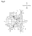
- the first acting position F1 is defined at a position overlapping with the drive shaft axis O as shown in Figs. 8 and 9 regardless of the inclination angle of the swash plate 5.
- the second acting position F2 which is shown in Fig. 1 , is defined at a position overlapping with the drive shaft axis O regardless of the inclination angle of the swash plate 5. That is, when the drive shaft 3 and the first and second acting positions F1, F2 are viewed from the D1 direction of Fig. 7 , the first and second acting portions 14a, 14b are each located on the acting surface 134 to overlap with the drive shaft axis O regardless of the inclination angle of the swash plate 5.
- the first cylindrical portion 131 has a rotation stopper 135, which restricts the movable body 13a from rotating about the drive shaft axis O.
- the rotation stopper 135 has a rectangular shape as shown in Fig. 7 and extends from the outer circumferential surface of the first cylindrical portion 131 toward the top dead center associated part T of the swash plate main portion 50.
- the rotation stopper 135 is located between the movable body main portion 130 and the swash plate main portion 50, more specifically, between the first swash plate arm 5e and the second swash plate arm 5f, which are shown in Fig. 3 .
- the rotation stopper 135 contacts the first swash plate arm 5e or the second swash plate arm 5f to restrict the movable body 13a from rotating about the drive shaft axis O. This allows the movable body 13a to be rotated integrally with the lug plate 51 and the swash plate 5 by rotation of the drive shaft 3.
- control pressure chamber 13b is defined by the second cylindrical portion 132, the coupling portion 133, the cylinder chamber 51a, and the drive shaft 3.
- the control pressure chamber 13b and the swash plate chamber 25 are sealed off from each other by the O-rings 49c, 49d.
- the drive shaft 3 has an axial passage 3a and a radial passage 3b.
- the axial passage 3a extends from the rear end of the drive shaft 3 toward the front end along the drive shaft axis O.
- the radial passage 3b extends in a radial direction from the front end of the axial passage 3a and opens in the outer circumferential surface of the drive shaft 3.
- the rear end of the axial passage 3a communicates with the pressure regulation chamber 31.
- the radial passage 3b communicates with control pressure chamber 13b as shown in Fig. 5 .
- the axial passage 3a and the radial passage 3b connect the pressure regulation chamber 31 to the control pressure chamber 13b.
- the drive shaft 3 has, at the front end, a threaded portion 3c.
- the drive shaft 3 is connected to a non-illustrated pulley or a non-illustrated electromagnetic clutch through the threaded portion 3c.
- Each piston 9 is accommodated in the corresponding one of the cylinder bores 21a and is allowed to reciprocate in the cylinder bore 21a.
- Each piston 9 and the valve assembly plate 23 define a compression chamber 57 in the corresponding cylinder bore 21a.
- Each piston 9 has an engaging portion 9a.
- Each engaging portion 9a accommodates a pair of hemispherical shoes 11a, 11b.
- the shoes 11a, 11b correspond to a conversion mechanism.
- Each shoe 11 a slides on the front surface 5a of the swash plate main portion 50.
- each shoe 11 b slides on the rear surface 5b of the swash plate main portion 50.
- the swash plate main portion 50 thus actuates the shoes 11a, 11b.
- the shoes 11a, 11b convert rotation of the swash plate 5 into reciprocation of the pistons 9, and the pistons 9 reciprocate in the cylinder bores 21a by a stroke corresponding to the inclination angle defied by the swash plate reference plane S.
- a wobble plate type conversion mechanism may be employed in which a wobble plate is provided on the rear surface 5b of the swash plate main portion 50 via a thrust bearing, and the wobble plate and the pistons 9 are connected to each other with connecting rods.
- the control mechanism 15 includes a low-pressure passage 15a, a high-pressure passage 15b, a control valve 15c, an orifice 15d, the axial passage 3a, and the radial passage 3b.
- the low-pressure passage 15a is connected to the pressure regulation chamber 31 and the suction chamber 33.
- the low-pressure passage 15a, the axial passage 3a, and the radial passage 3b connect the control pressure chamber 13b, the pressure regulation chamber 31, and the suction chamber 33 to one another.
- the high-pressure passage 15b is connected to the pressure regulation chamber 31 and the discharge chamber 35.
- the high-pressure passage 15b, the axial passage 3a, and the radial passage 3b connect the control pressure chamber 13b, the pressure regulation chamber 31, and the discharge chamber 35 to one another.
- the control valve 15c is arranged in the low-pressure passage 15a.
- the low-pressure control valve 15c is allowed to adjust the opening degree of the low-pressure passage 15a based on the pressure in the suction chamber 33.
- the high-pressure passage 15b also has the orifice 15d.
- a pipe connected to the evaporator is connected to the inlet 250 shown in Fig. 1
- a pipe connected to the condenser is connected to the outlet.
- the condenser is connected to the evaporator via a pipe and an expansion valve.
- the drive shaft 3 rotates to rotate the swash plate 5, thus reciprocating each piston 9 in the corresponding cylinder bore 21a.
- This varies the volume of each compression chamber 57 in accordance with the piston stroke.
- the refrigerant that has been drawn from the evaporator into the swash plate chamber 25 through the inlet 250 flows through the suction passage 39 and the suction chamber 33 and is compressed in the compression chambers 57.
- the refrigerant that is compressed in the compression chambers 57 is discharged to the discharge chamber 35 and is discharged to the condenser through the outlet.
- the actuator 13 changes the inclination angle of the swash plate 5 to increase or decrease the stroke of the pistons 9, thereby varying the displacement of the compressor.
- the first acting portion 14a pushes the first receiving portion 6a along the drive shaft axis O toward the rear of the swash plate chamber 25.
- the second acting portion 14b pushes the second receiving portion 6b along the drive shaft axis O toward the rear of the swash plate chamber 25. Therefore, the first and second swash plate arms 5e, 5f slide on the first and second guide surfaces 57a, 57b, respectively, toward the drive shaft axis O.
- the swash plate 5 decreases the inclination angle while substantially maintaining the position of the top dead center associated part T. This reduces the stroke of the pistons 9 and the displacement of the compressor per rotation of the drive shaft 3. When reaching the minimum inclination angle shown in the drawing, the swash plate 5 contacts the restoration spring 37.
- the reaction force acting on the swash plate 5 and the urging force of the restoration spring 37 cause the first and second swash plate arms 5e, 5f to slide on the first and second guide surfaces 57a, 57b, respectively, to move away from the drive shaft axis O.
- the swash plate 5 thus increases the inclination angle while substantially maintaining the position of the top dead center associated part T. This increases the stroke of the pistons 9 and thus increases the displacement of the compressor per rotation of the drive shaft 3.
- the inclination angle of the swash plate 5 is maximized in the drawing, the displacement per rotation of the drive shaft 3 is maximized.
- a part of the first receiving surface 54a on the front surface 5a of the swash plate main portion 50 serves as the first receiving portion 6a.
- the first receiving portion 6a is pushed while making line contact with the first acting portion 14a provided on the movable body 13a at the first acting position F1.
- a part of the second receiving surface 54b on the front surface 5a serves as the second receiving portion 6b.
- the second receiving portion 6b is pushed while making line contact with the second acting portion 14b provided on the movable body 13a at the second acting position F2. Accordingly, the inclination angle of the swash plate 5 is reduced.
- the movable body 13a pushes the swash plate 5 along the drive shaft axis O, while making line contact with the swash plate 5 via the first and second acting positions F1, F2. Since the compressor has no sleeve such as a conventional hinge ball between the movable body 13a and the swash plate 5, the size of the compressor is reduced, accordingly. Thus, it is possible to increase the size of the movable body 13a so that the movable body 13a is moved by a greater thrust without increasing the overall size of the compressor.
- the movable body 13a pushes the swash plate 5 while directly contacting the swash plate 5, the direction of the load acting on the swash plate 5 resists change. That is, the movable body 13a is not easily inclined in any direction other than the direction in which the drive shaft axis O extends, and resists warping. Therefore, the movable body 13a is reliably allowed to push the swash plate 5 along the drive shaft axis O, so that the movable body 13a stably reduces the inclination angle of the swash plate 5. Since the orientation of the movable body 13a is stabilized, pressure leakage in the control pressure chamber 13b is unlikely to occur.
- the first acting portion 14a pushes the first receiving portion 6a at the first acting position F1
- the second acting portion 14b pushes the second receiving portion 6b at the second acting position F2. Accordingly, when the inclination angle of the swash plate 5 is reduced, the movable body 13a pushes the swash plate 5 at two positions, or the first acting position F1 and the second acting position F2, which are on opposite sides of the top dead center plane D.
- the first and second acting positions F1, F2 overlap with the drive shaft axis O as shown in Figs. 8 and 9 regardless of the inclination angle of the swash plate 5.
- the first and second acting portions 14a, 14b are allowed to push the first and second receiving portions 6a, 6b at positions close to the drive shaft axis O, respectively.
- the movable body 13a pushes the swash plate 5 via the first and second acting positions F1, F2, the swash plate 5 is not easily inclined in a direction other than the direction in which the inclination angle is changed and thus resists warping.
- the movable body 13a is allowed to smoothly move along the drive shaft axis O.
- the compressor according to the first embodiment achieves a sufficient controllability, while minimizing the size.
- the reaction force that acts from the pistons 9 to the swash plate 5 during operation of the compressor generates moment that acts to rotate the swash plate 5 in a direction other than the direction in which the inclination angle is changed.
- the guide surfaces 52a, 52b in the through hole 5d of the compressor slide on the outer circumferential surface 30 of the drive shaft 3 in response to changes in the inclination angle of the swash plate 5. Then, the swash plate 5 is guided by the link mechanism 7 and the drive shaft 3 along the drive shaft axis O and in the direction of the inclination angle, so that the inclination angle is changed as described above.
- the guide surfaces 52a, 52b allow the swash plate 5 to easily contact the outer circumferential surface 30 of the drive shaft 3 at two points on opposite sides of the drive shaft axis O. Therefore, the compressor reliably prevents the swash plate 5 from being warped by the moment. Since the compressor has no sleeve, the number of components is reduced, and the manufacturing costs are reduced, accordingly.
- the first and second acting portions 14a, 14b are provided on the acting surface 134, and the first and second acting portions 14a, 14b protrude toward the first and second receiving surfaces 54a, 54b, respectively. This allows the first and second receiving surfaces 54a, 54b, and thus the first and second receiving portions 6a, 6b, to be flat and parallel with the swash plate reference plane S, facilitating the production of the swash plate 5. In this respect also, the production costs for the compressor are reduced.
- the rotation stopper 135 restricts the movable body 13a from rotating about the drive shaft axis O.
- the first and second acting portions 14a, 14b are prevented from pushing the first and second receiving portions 6a, 6b at positions offset from positions overlapping with the drive shaft axis O, respectively.
- the first and second receiving surfaces 54a, 54b of the compressor according to the first embodiment are replaced by a receiving surface 54c as shown in Fig. 10 .
- the receiving surface 54c is also arranged on the front surface 5a of the swash plate main portion 50 and about the through hole 5d.
- the receiving surface 54c has a flat section 540 and first and second protrusions 6c, 6d. As shown in Fig. 13 , the flat section 540 is a flat surface parallel with the swash plate reference plane S.
- the first protrusion 6c extends along the drive shaft axis O and in a direction from the flat section 540 toward the movable body main portion 130.
- the distal end of the first protrusion 6c that is, the part that faces the movable body main portion 130, has a cylindrical shape protruding toward the movable body 13a.
- the second protrusion 6d which is shown in Fig. 10 , has the same structure as the first protrusion surface 6c.
- the first and second protrusions 6c, 6d correspond to first and second receiving portions.
- the first protrusion 6c and the second protrusion 6d are provided on the flat section 540 at positions on opposite sides of the top dead center plane D. Further, the first protrusion 6c and the second protrusion 6d are located on the flat section 540 to be plane-symmetrical with respect to the top dead center plane D.
- the drive shaft 3 is passed through the through hole 5d, the drive shaft 3 is located between the first protrusion 6c and the second protrusion 6d. Further, the first protrusion 6c and the second protrusion 6d are located at positions slightly closer to the top dead center associated part T than the drive shaft axis O.
- the acting surface 134 of the movable body 13a is a flat surface perpendicular to the drive shaft axis O.
- a part of the acting surface 134 that makes line contact with the first protrusion 6c at the first acting position F3 serves as a first acting portion 16a.
- a part of the acting surface 134 that makes line contact with the second protrusion 6d at the second acting position F4 serves as a second acting portion 16b.
- the first acting position F3 overlaps with the drive shaft 3 and is located at a position slightly closer to the top dead center associated part T than the drive shaft axis O as shown in Fig. 13 regardless of the inclination angle of the swash plate 5.
- the second acting position F4, which is shown in Fig. 12 has the same structure as the first acting position F3.
- the movable body 13a of this compressor does not have the rotation stopper 135 in the first cylindrical portion 131.
- the cross-sectional shape of the movable body 13a along a given plane containing the drive shaft axis O is line-symmetric with respect to the drive shaft axis O.
- the other components of the compressor of the second embodiment are configured identically with the corresponding components of the compressor of the first embodiment. Accordingly, these components are identified by the same reference numbers, and detailed description thereof is omitted herein.
- the first acting portion 16a pushes the first protrusion 6c toward the rear of the swash plate chamber 25 at the first acting position F3. Also, at the second acting position F4, the second acting portion 16b pushes the second protrusion 6d along the drive shaft axis O toward the rear of the swash plate chamber 25.
- the first and second acting positions F3, F4 overlap with the drive shaft 3 and are located at positions slightly closer to the top dead center associated part T than the drive shaft axis O regardless of the inclination angle of the swash plate 5.
- the first and second acting portions 16a, 16b are allowed to push the first and second protrusions 6c, 6d at positions close to the drive shaft axis O, respectively.
- the movable body 13a pushes the swash plate 5 via the first and second acting positions F3, F4, the swash plate 5 is not easily inclined in a direction other than the direction in which the inclination angle is changed and thus resists warping.
- the movable body 13a is allowed to smoothly move along the drive shaft axis O.
- the first and second acting positions F3, F4 are respectively defined at positions slightly closer to the top dead center associated part T than the drive shaft axis O.
- the stroke of the movable body 13a along the drive shaft axis O is reduced when the inclination angle of the swash plate 5 is changed in the present embodiment.
- parts of the acting surface 134 serve as the first acting portion 16a and the second acting portion 16b.
- the movable body 13a is permitted to rotate about the drive shaft axis O to some extent, so that there is no need to provide a member such as the rotation stopper 135 for restricting the movable body 13a from rotating about the drive shaft axis O.
- This allows the cross-sectional shape of the movable body 13a along a given plane containing the drive shaft axis O to be line-symmetric with respect to the drive shaft axis O, thereby facilitating the production of the movable body 13a.
- the production costs for the compressor are reduced.
- a part of the acting surface 134 makes line contact with the first protrusion 6c at the fist acting position F3 and another part of the acting surface 134 makes line contact with the second protrusion 6d at the second acting position F4 without restricting the movable body 13a from rotating about the drive shaft axis O by the rotation stopper 135 as in the compressor of the first embodiment. Therefore, when the inclination angle of the swash plate 5 is reduced, the first and second acting positions F3, F4 are not displaced from positions overlapping with the drive shaft 3 and slightly closer to the top dead center associated part T than the drive shaft axis O regardless of the inclination angle of the swash plate 5.
- the other operations of the compressor are the same as the corresponding operations of the compressor of the first embodiment.
- the compressor of the third embodiment has a receiving surface 54d as shown in Fig. 14 .
- the receiving surface 54d is also arranged on the front surface 5a of the swash plate main portion 50 and about the through hole 5d.
- the receiving surface 54d has a mortar portion 541 and first and second protrusions 6e, 6f. As shown in Fig. 17 , the mortar portion 541 has a decreasing diameter along the drive shaft axis O to conform to the acting surface 134 regardless of the inclination angle of the swash plate 5.
- the first protrusion 6e extends in a direction from the mortar portion 541 toward the movable body main portion 130.
- the distal end of the first protrusion 6e has a cylindrical shape protruding toward the movable body 13a.
- the second protrusion 6f which is shown in Fig. 14 , has the same structure as the first protrusion 6e.
- the first and second protrusions 6e, 6f correspond to first and second receiving portions, respectively.
- the first protrusion 6e and the second protrusion 6f are located on the mortar portion 541 at positions on opposite sides of the top dead center plane D. Further, the first protrusion 6e and the second protrusion 6f are located on the mortar portion 541 to be plane-symmetrical with respect to the top dead center plane D.
- the drive shaft 3 is passed through the through hole 5d, the drive shaft 3 is located between the first protrusion 6e and the second protrusion 6f. Further, the first protrusion 6e and the second protrusion 6f are located at positions slightly closer to the top dead center associated part T than the drive shaft axis O.
- the acting surface 134 of the movable body 13a has a truncated conical shape with a diameter decreasing from the outer circumference of the first cylindrical portion 131 toward the drive shaft axis O.
- a part of the acting surface 134 that makes line contact with the first protrusion 6e at the first acting position F5 serves as a first acting portion 18a.
- a part of the acting surface 134 that makes line contact with the second protrusion 6f at the second acting position F6 serves as a second acting portion 18b.
- the first acting position F5 overlaps with the drive shaft 3 and is located at a position slightly closer to the top dead center associated part T than the drive shaft axis O as shown in Fig. 17 regardless of the inclination angle of the swash plate 5.
- the second acting position F6, which is shown in Fig. 16 has the same structure as the first acting position F5.
- the movable body 13a of this compressor also does not have the rotation stopper 135 in the first cylindrical portion 131.
- the cross-sectional shape of the movable body 13a along a given plane containing the drive shaft axis O is line-symmetric with respect to the drive shaft axis O.
- the other structures of the compressor are the same as the corresponding structures of the compressor of the first embodiment.
- the first and second acting positions F5, F6 overlap with the drive shaft 3 and are located at positions slightly closer to the top dead center associated part T than the drive shaft axis O regardless of the inclination angle of the swash plate 5.
- the first and second acting portions 18a, 18b are allowed to push the first and second protrusions 6c, 6d at positions close to the drive shaft axis O, respectively.
- the stroke of the movable body 13a along the drive shaft axis O is reduced when the inclination angle of the swash plate 5 is changed in the present embodiment.
- the acting surface 134 has a shape like a truncated cone, the diameter of which decreases from the outer circumference of the first cylindrical portion 131 toward the drive shaft axis O.
- the mortar portion 541 has a shape that conforms to the acting surface 134 regardless of the inclination angle.
- the swash plate 5 changes the inclination angle while being aligned with the movable body 13a. Therefore, when the inclination angle of the swash plate 5 is changed, no vibrations are generated in the swash plate 5. This allows the inclination angle to be reliably changed.
- parts of the acting surface 134 serve as the first acting portion 18a and the second acting portion 18b, and there is no need to provide a member such as the rotation stopper 135 for restricting the movable body 13a from rotating about the drive shaft axis O.
- This allows the cross-sectional shape of the movable body 13a along a given plane containing the drive shaft axis O to be line-symmetric with respect to the drive shaft axis O, thereby facilitating the production of the movable body 13a.
- a part of the acting surface 134 makes line contact with the first protrusion 6e at the fist acting position F5 and another part of the acting surface 134 makes line contact with the second protrusion 6f at the second acting position F6 without restricting the movable body 13a from rotating about the drive shaft axis O by the rotation stopper 135 as in the compressor of the second embodiment. Therefore, when the inclination angle of the swash plate 5 is reduced, the first and second acting positions F5, F6 are not displaced from positions overlapping with the drive shaft 3 and slightly closer to the top dead center associated part T than the drive shaft axis O regardless of the inclination angle of the swash plate 5.
- the other operations of the compressor are the same as the corresponding operations of the compressor of the first embodiment.
- the first and second acting positions F1, F2 may be located at any positions regardless of the inclination angle of the swash plate 5 as long as these positions overlap with the drive shaft 3.
- the first and second acting positions F1, F2 may be located at positions slightly closer to the top dead center associated part T than the drive shaft axis O or positions closer to the bottom dead center associated part U.
- the modification may be applied to the compressors of the first and second embodiments.
- the first and second acting portions 14a, 14b and the first and second receiving portions 6a, 6b may be configured to make point contact with each other at the first and second acting positions F1, F2, respectively.
- the same modification may be applied to the first and second protrusions 6c to 6f of the compressor according to the first and second embodiments.
- the compressor according to the first embodiment may be configured such that only one of the first acting portion 14a and the second acting portion 14b is provided on the acting surface 134, and one of the first receiving surface 54a and the second receiving surface 54b, which correspond to the first acting portion 14a or the second acting portion 14b, may be provided on the front surface 5a of the swash plate main portion 50.
- the first protrusions 6c, 6e or the second protrusions 6d, 6f may be provided on the flat section 540 or the mortar portion 541.
- the receiving surface 54d may be configured without the first and second protrusions 6e, 6f.
- the compressor according to the first embodiment may be configured such that the inclination angle of the swash plate 5 is increased when the first and second acting portions 14a, 14b push the first and second receiving portions 6a, 6b along the drive shaft axis O, respectively.
- the same modification may be applied to the compressors of the second and third embodiments.
- control valve 15c may be provided in the high-pressure passage 15b, and the orifice 15d may be provided in the low-pressure passage 15a.
- the control valve 15c is allowed to adjust the flow rate of high-pressure refrigerant flowing through the high-pressure passage 15b. This allows the high-pressure in the discharge chamber 35 to promptly increase the pressure in the control pressure chamber 13b and to promptly reduce the displacement.
- the control valve 15c may be replaced by a three-way valve connected to the low-pressure passage 15a and the high-pressure passage 15b. In this case, the opening degree of the three-way valve is adjusted to regulate the flow rate of refrigerant flowing through the low-pressure passage 15a and the high-pressure passage 15b.
Abstract
Description
- The present invention relates to a variable displacement swash-plate compressor.
-
Japanese Laid-Open Patent Publication No. 52-131204 - The link mechanism includes a lug member, a hinge ball, and a link. The lug member is located in the swash plate chamber and is fixed to the drive shaft. The hinge ball is fitted about the drive shaft to be arranged in the through hole of the swash plate. This causes the outer circumferential surface of the hinge ball to contact the through hole. The link is provided between the lug member and the swash plate. The link connects the swash plate to the lug member, so that the swash plate is permitted to pivot.
- The actuator includes the lug member, a movable body, and a control pressure chamber. The movable body has a cylindrical shape. The movable body is fitted about the drive shaft to be arranged between the lug member and the hinge ball. When the movable body and the hinge ball contact each other, the movable body is engaged with the swash plate via the hinge ball. When moving along the drive shaft axis, the movable body changes the inclination angle of the swash plate. The control pressure chamber, which is defined by the lug member and the movable body, uses its internal pressure to move the movable body.
- In this compressor, when the control mechanism connects the discharge chamber and the control pressure chamber with each other using the pressure regulation valve, the pressure in the control pressure chamber is increased. This moves the movable body along the axis of the drive shaft and pushes the hinge ball along the axis of the drive shaft. Accordingly, the hinge ball is moved along the axis of the drive shaft, and the swash plate slides on the hinge ball in the direction reducing the inclination angle. This allows the displacement of the compressor per rotation of the drive shaft to be reduced.
- However, in the above described compressor, the movable body of the actuator and the swash plate are engaged with each other via the hinge ball. Thus, the size of the entire compressor needs to be increased to increase the size of the movable body so that the movable body is easily moved with a great thrust.
- When decreasing the inclination angle of the swash plate in the compressor, the movable body pushes the swash plate via the hinge ball. The tolerance during manufacture is likely to vary contacting positions between the outer circumferential surface of the hinge ball and the swash plate. Accordingly, when the movable body pushes the hinge ball, the direction of the load acting on the swash plate is likely to change. Thus, the movable body cannot smoothly move the hinge ball along the axis of the drive shaft, and the movable body cannot stably decrease the inclination angle of the swash plate. Also, the orientation of the movable body tends to be unstable, which can result in pressure leakage in the control pressure chamber. In this case, the displacement cannot be quickly changed in response to changes in the driving state of machinery on which the compressor is mounted, such as a vehicle, and high controllability cannot be achieved.
- An objective of the present invention is to provide a variable displacement swash-plate compressor that achieves a sufficient controllability while minimizing the size.
- To achieve the foregoing objective and in accordance with one aspect of the present invention, a variable displacement swash-plate compressor is provided that includes a housing having a swash plate chamber and a cylinder bore, a drive shaft that is rotationally supported by the housing, a swash plate that is supported in the swash plate chamber and is rotational by rotation of the drive shaft, a link mechanism, a piston, a conversion mechanism, an actuator, and a control mechanism. The link mechanism is arranged between the drive shaft and the swash plate, and allows an inclination angle of the swash plate to be changed with respect to a direction perpendicular to a drive shaft axis of the drive shaft. The piston is reciprocally received in the cylinder bore. The conversion mechanism causes the piston to reciprocate in the cylinder bore by a stroke corresponding to the inclination angle of the swash plate through rotation of the swash plate. The actuator is configured to change the inclination angle. The control mechanism controls the actuator. The link mechanism includes a lug member that is located in the swash plate chamber and is fixed to the drive shaft and a transmitting member that transmits rotation of the lug member to the swash plate. The swash plate has a through hole, which slides on an outer circumference of the drive shaft in response to changes in the inclination angle. The swash plate is guided by the link mechanism and the through hole along the drive shaft axis and in a direction of the inclination angle, thereby changing the inclination angle. The actuator includes the lug member, a movable body, and a control pressure chamber. The movable body is located between the lug member and the swash plate and is configured to rotate integrally with the swash plate and to move along the drive shaft axis, thereby changing the inclination angle. The control pressure chamber is defined by the lug member and the movable body and is configured such that pressure in the control pressure chamber is changed by the control mechanism to move the movable body. The movable body includes an acting portion that is configured to push the swash plate with the pressure in the control pressure chamber. The swash plate includes a receiving portion that contacts and is pushed by the acting portion. The acting portion and the receiving portion contact each other at an acting position. Atop dead center associated part for positioning the piston at a top dead center is defined on the swash plate. When the drive shaft and the acting position are viewed from a direction that is perpendicular to a top dead center plane containing the top dead center associated part and the drive shaft axis, the acting position is defined at a position overlapping with the drive shaft regardless of the inclination angle.
- Other aspects and advantages of the present invention will become apparent from the following description, taken in conjunction with the accompanying drawings, illustrating by way of example the principles of the invention.
- The invention, together with objects and advantages thereof, may best be understood by reference to the following description of the presently preferred embodiments together with the accompanying drawings in which:
-
Fig. 1 is a cross-sectional view of a compressor according to a first embodiment at the minimum displacement; -
Fig. 2 is a schematic diagram showing the control mechanism of the compressor according to the first embodiment; -
Fig. 3 is a schematic front view of the swash plate of the compressor according to the first embodiment; -
Fig. 4 is a rear view of the lug plate of the compressor according to the first embodiment; -
Fig. 5 is an enlarged partial cross-sectional view showing the lug plate and the movable body of the compressor according to the first embodiment; -
Fig. 6 is a side view of the movable body of the compressor according to the first embodiment; -
Fig. 7 is a rear view of the movable body of the compressor according to the first embodiment; -
Fig. 8 is an enlarged partial cross-sectional view of the compressor according to the first embodiment in a state of the maximum displacement, in which the drive shaft and the first and second acting positions are viewed from a D1 direction inFig. 7 ; -
Fig. 9 is an enlarged partial cross-sectional view of the compressor according to the first embodiment in a state of the minimum displacement, in which the drive shaft and the first and second acting positions are viewed from a D1 direction inFig. 7 ; -
Fig. 10 is a schematic front view of the swash plate of a compressor according to a second embodiment; -
Fig. 11 is a side view of the movable body of the compressor according to the second embodiment; -
Fig. 12 is a rear view of the movable body of the compressor according to the second embodiment; -
Fig. 13 is an enlarged partial cross-sectional view of the compressor according to the second embodiment in a state of the minimum displacement, in which the drive shaft and the first and second acting positions are viewed from a D1 direction inFig. 12 ; -
Fig. 14 is a schematic front view of the swash plate of a compressor according to a third embodiment; -
Fig. 15 is a side view of the movable body of the compressor according to the third embodiment; -
Fig. 16 is a rear view of the movable body of the compressor according to the third embodiment; and -
Fig. 17 is an enlarged partial cross-sectional view of the compressor according to the third embodiment in a state of the minimum displacement, in which the drive shaft and the first and second acting positions are viewed from a D1 direction inFig. 16 . - First to third embodiments of the present invention will now be described with reference to the drawings. Compressors according to the first to third embodiments are variable displacement swash-plate compressors with single-headed pistons. These compressors are installed in vehicles and are each included in the refrigeration circuit in the air conditioner for the vehicle.
- As shown in
Fig. 1 , the compressor according to the first embodiment includes a housing 1, adrive shaft 3, aswash plate 5, alink mechanism 7,pistons 9, pairs ofshoes actuator 13, and acontrol mechanism 15, which is illustrated inFig. 2 . - As shown in
Fig. 1 , the housing 1 has afront housing member 17 at a front position in the compressor, arear housing member 19 at a rear position in the compressor, and acylinder block 21 and avalve assembly plate 23, which are arranged between thefront housing member 17 and therear housing member 19. - The
front housing member 17 includes afront wall 17a, which extends in the vertical direction of the compressor on the front side, and acircumferential wall 17b, which is integrated with thefront wall 17a and extends rearward from the front of the compressor. Thefront housing member 17 has a substantially cylindrical cup shape with thefront wall 17a and thecircumferential wall 17b. Furthermore, thefront wall 17a and thecircumferential wall 17b define aswash plate chamber 25 in thefront housing member 17. - The
front wall 17a has aboss 17c, which projects forward. Theboss 17c accommodates ashaft sealing device 27. Theboss 17c has afirst shaft hole 17d, which extends in the front-rear direction of the compressor. Thefirst shaft hole 17d accommodates afirst slide bearing 29a. - The
circumferential wall 17b has aninlet 250, which communicates with theswash plate chamber 25. Theswash plate chamber 25 is connected to a non-illustrated evaporator through theinlet 250. Since low-pressure refrigerant gas that has passed through the evaporator flows into theswash plate chamber 25 via theinlet 250, the pressures in theswash plate chamber 25 is lower than the pressure in adischarge chamber 35, which will be discussed below. - A part of the
control mechanism 15 is received in therear housing member 19. Therear housing member 19 includes a firstpressure regulation chamber 31a, asuction chamber 33, and thedischarge chamber 35. The firstpressure regulation chamber 31a is located in the central part of therear housing member 19. Thedischarge chamber 35 has an annular shape and is located in a radially outer part of therear housing member 19. Also, thesuction chamber 33 has an annular shape between the firstpressure regulation chamber 31a and thedischarge chamber 35 in therear housing member 19. Thedischarge chamber 35 is connected to a non-illustrated outlet. - The
cylinder block 21 includes cylinder bores 21a, the number of which is the same as that of thepistons 9. The cylinder bores 21a are arranged at equal angular intervals in the circumferential direction. The front end of the eachcylinder bore 21a communicates with theswash plate chamber 25. Thecylinder block 21 also includesretainer grooves 21 b, which limit the lift ofsuction reed valves 41a, which will be discussed below. - The
cylinder block 21 further includes asecond shaft hole 21c, which communicates with theswash plate chamber 25 and extends in the front-rear direction of the compressor. Thesecond shaft hole 21c accommodates a second slide bearing 29b. The first slide bearing 29a and the second slide bearing 29b may be replaced by rolling-element bearings. - The
cylinder block 21 further has aspring chamber 21d. Thespring chamber 21d is located between theswash plate chamber 25 and thesecond shaft hole 21c. Thespring chamber 21d accommodates arestoration spring 37. Therestoration spring 37 urges theswash plate 5 forward of theswash plate chamber 25 when the inclination angle is minimized. Thecylinder block 21 also includes asuction passage 39, which communicates with theswash plate chamber 25. - The
valve assembly plate 23 is located between therear housing member 19 and thecylinder block 21. Thevalve assembly plate 23 includes avalve base plate 40, asuction valve plate 41, adischarge valve plate 43, and aretainer plate 45. - The
valve base plate 40, thedischarge valve plate 43, and theretainer plate 45 includesuction ports 40a, the number of which is equal to that of the cylinder bores 21 a. Furthermore, thevalve base plate 40 and thesuction valve plate 41 includedischarge ports 40b, the number of which is equal to that of the cylinder bores 21a. The cylinder bores 21a communicate with thesuction chamber 33 through thesuction ports 40a and communicate with thedischarge chamber 35 through thedischarge ports 40b. Furthermore, thevalve base plate 40, thesuction valve plate 41, thedischarge valve plate 43, and theretainer plate 45 include afirst communication hole 40c and asecond communication hole 40d. Thefirst communication hole 40c connects thesuction chamber 33 to thesuction passage 39. This causes theswash plate chamber 25 to communicate with thesuction chamber 33. - The
suction valve plate 41 is provided on the front surface of thevalve base plate 40. Thesuction valve plate 41 includessuction reed valves 41a, which are allowed to selectively open and close thesuction ports 40a by elastic deformation. Thedischarge valve plate 43 is located on the rear surface of thevalve base plate 40. Thedischarge valve plate 43 includesdischarge reed valves 43a, which are allowed to selectively open and close thedischarge ports 40b by elastic deformation. Theretainer plate 45 is provided on the rear surface of thedischarge valve plate 43. Theretainer plate 45 limits the maximum opening degree of thedischarge reed valves 43a. - The
drive shaft 3 has a cylindrical outercircumferential surface 30. Thedrive shaft 3 is inserted in theboss 17c toward the rear of the housing 1. The front portion of thedrive shaft 3 is supported by theshaft sealing device 27 in theboss 17c and is supported by the first slide bearing 29a in thefirst shaft hole 17d. The rear portion of thedrive shaft 3 is supported by the second slide bearing 29b in thesecond shaft hole 21c. In this manner, thedrive shaft 3 is supported by the housing 1 to be rotational about the drive shaft axis O. Thesecond shaft hole 21c and the rear end of thedrive shaft 3 define a secondpressure regulation chamber 31 b. The secondpressure regulation chamber 31 b communicates with the firstpressure regulation chamber 31a through thesecond communication hole 40d. The first and secondpressure regulation chambers pressure regulation chamber 31. - O-
rings drive shaft 3. The O-rings drive shaft 3 and thesecond shaft hole 21c to seal off theswash plate chamber 25 and thepressure regulation chamber 31 from each other. - The
link mechanism 7, theswash plate 5, and theactuator 13 are mounted on thedrive shaft 3. Thelink mechanism 7 includes first and secondswash plate arms swash plate 5 shown inFig. 3 , alug plate 51 shown inFig. 4 , and first andsecond lug arms lug plate 51. The first and secondswash plate arms lug plate 51 corresponds to a lug member. For illustrative purposes, part of the secondswash plate arm 5f is omitted by using a break line. - As shown in
Fig. 3 , theswash plate 5 has a swash platemain portion 50, aswash plate weight 5c, and the first and secondswash plate arms - The swash plate
main portion 50 is shaped as a flat annular plate and has afront surface 5a and arear surface 5b. Atop dead center associated part T for positioning eachpiston 9 at the top dead center and a bottom dead center associated part U for positioning eachpiston 9 at the bottom dead center are defined on the swash platemain portion 50. Also, as shown inFig. 3 , an imaginary top dead center plane D is defined in this compressor. The top dead center plane D includes the top dead center associated part T, the bottom dead center associated part U, and the drive shaft axis O. Further, as shown inFig. 8 , the swash platemain portion 50 includes an imaginary swash plate reference plane S for determining the inclination angle of theswash plate 5 in relation to a direction perpendicular to the drive shaft axis O. The swash plate reference plane S is parallel with thefront surface 5a and therear surface 5b. - As shown in
Fig. 3 , the swash platemain portion 50 includes a throughhole 5d. Thedrive shaft 3 is inserted in the throughhole 5d. Twoflat guide surfaces hole 5d. When thedrive shaft 3 is inserted in the throughhole 5d, the guide surfaces 52a, 52b contact the outercircumferential surface 30 of thedrive shaft 3. - First and
second receiving surfaces main portion 50 about the throughhole 5d. The first andsecond receiving surfaces Fig. 8 , thefirst receiving surface 54a is a flat surface parallel with the swash plate reference plane S. Thesecond receiving surface 54b, which is shown inFig. 3 , has the same structure as thefirst receiving surface 54a. Thefirst receiving surface 54a and thesecond receiving surface 54b are arranged on thefront surface 5a at positions on opposite sides of the top dead center plane D. When thedrive shaft 3 is passed through the throughhole 5d, thedrive shaft 3 is located between thefirst receiving surface 54a and thesecond receiving surface 54b. - A part of the
first receiving surface 54a that makes line contact with afirst acting portion 14a at a first acting position F1, which will be discussed below, is afirst receiving portion 6a. Likewise, a part of thesecond receiving surface 54b that makes line contact with asecond acting portion 14b at a second acting position F2, which will be discussed below, is asecond receiving portion 6b. As described above, thefirst receiving surface 54a and thesecond receiving surface 54b are arranged on thefront surface 5a at positions on opposite sides of the top dead center plane D. Thus, the first receivingportion 6a and thesecond receiving portion 6b are also located on opposite sides of the top dead center plane D. Since the first andsecond receiving surfaces second receiving portions - The
swash plate weight 5c is provided on thefront surface 5a at a position closer to the bottom dead center associated part U than the drive shaft axis O. That is, theswash plate weight 5c is located between the drive shaft axis O and the bottom dead center associated part U. As shown inFig. 1 , theswash plate weight 5c has a substantially semi-circular cylindrical shape and extends from thefront surface 5a toward amovable body 13a, which will be discussed below. - The first and second
swash plate arms front surface 5a at positions closer to the top dead center associated part T than the drive shaft axis O. Specifically, the first and secondswash plate arms swash plate arm 5e and the secondswash plate arm 5f are arranged on thefront surface 5a at positions on opposite sides of the top dead center plane D. As shown inFig. 1 , the first and secondswash plate arms front surface 5a toward thelug plate 51. For illustrative purposes, the shapes of theswash plate weight 5c and the first and secondswash plate arms Fig. 3 . The same applies toFigs. 10 and14 , which will be discussed below. - As shown in
Fig. 4 , thelug plate 51 has a substantially annular shape with a throughhole 510. Thedrive shaft 3 is press-fitted in the throughhole 510, so that thelug plate 51 rotates integrally with thedrive shaft 3. As shown inFig. 1 , athrust bearing 55 is located between thelug plate 51 and thefront wall 17a. - As shown in
Fig. 5 , thelug plate 51 has a recessedcylinder chamber 51a. Thecylinder chamber 51a has a cylindrical shape coaxial with and extending along the drive shaft axis O. Thecylinder chamber 51a communicates with theswash plate chamber 25 at the rear. - As shown in
Fig. 4 , thefirst lug arm 53a and thesecond lug arm 53b are provided on thelug plate 51 at positions on opposite sides of the top dead center plane D. On thelug plate 51, the first andsecond lug arms main portion 50 than the drive shaft axis O and extend from thelug plate 51 toward theswash plate 5. That is, the first andsecond lug arms lug plate 51. - The
lug plate 51 has first andsecond guide surfaces second lug arms first guide surface 57a and thesecond guide surface 57b are also located on opposite sides of the top dead center plane D. As shown inFig. 1 , thefirst guide surface 57a is inclined such that the distance from theswash plate 5 gradually decreases from the outer circumference of thelug plate 51 toward thecylinder chamber 51a. Thesecond guide surface 57b has the same shape as thefirst guide surface 57a. - In this compressor, the first and second
swash plate arms second lug arms swash plate 5 to thedrive shaft 3. Thelug plate 51 and theswash plate 5 are thus coupled to each other with the first and secondswash plate arms second lug arms lug plate 51 is transmitted from the first andsecond lug arms swash plate arms swash plate 5 rotates with thelug plate 51 in theswash plate chamber 25. - Since the first and second
swash plate arms second lug arms swash plate arm 5e contacts thefirst guide surface 57a, and the distal end of the secondswash plate arm 5f contacts thesecond guide surface 57b. The first and secondswash plate arms second guide surfaces swash plate 5 is allowed to change its inclination angle, which is defined by the swash plate reference plane S, between the minimum inclination angle shown inFigs. 1 and9 and the maximum inclination angle shown inFig. 8 , while substantially maintaining the position of the top dead center associated part T. - As shown in
Fig. 5 , theactuator 13 includes thelug plate 51, amovable body 13a, and acontrol pressure chamber 13b. - As shown in
Fig. 6 , themovable body 13a is fitted about thedrive shaft 3. Themovable body 13a is thus located between thelug plate 51 and theswash plate 5 to move along the drive shaft axis O while sliding on thedrive shaft 3. Themovable body 13a has a substantially cylindrical shape coaxial with thedrive shaft 3. Specifically, themovable body 13a has a movable bodymain portion 130. - The movable body
main portion 130 includes a firstcylindrical portion 131, a secondcylindrical portion 132, and acoupling portion 133. The firstcylindrical portion 131 is located at a position facing theswash plate 5 in themovable body 13a and extends along the drive shaft axis O. The firstcylindrical portion 131 has the smallest outer diameter in the movable bodymain portion 130. As shown inFig. 5 , aring groove 131a is provided in the inner circumferential surface of the firstcylindrical portion 131. An O-ring 49c is fitted in thering groove 131a. The secondcylindrical portion 132 is located at a position on the movable bodymain portion 130 that faces thelug plate 51, that is, on in a front portion of themovable body 13a. The secondcylindrical portion 132 has a diameter larger than that of the firstcylindrical portion 131 and has the largest outer diameter in the movable bodymain portion 130. The secondcylindrical portion 132 has aring groove 132a in the outer circumferential surface. An O-ring 49d is fitted in thering groove 132a. Thecoupling portion 133 has an outer diameter that gradually increases from the firstcylindrical portion 131 toward the secondcylindrical portion 132 and couples the firstcylindrical portion 131 and the secondcylindrical portion 132 to each other. - As shown in
Fig. 6 , the firstcylindrical portion 131 has an actingsurface 134 at the rear end, that is, at a position that faces theswash plate 5. The actingsurface 134 has a shape like a truncated cone, the diameter of which decreases from the outer circumference of the firstcylindrical portion 131 toward the drive shaft axis O. - As shown in
Fig. 7 , the first andsecond acting portions surface 134. As shown inFig. 8 , thefirst acting portion 14a extends along the drive shaft axis O in a direction from the actingsurface 134 toward thefirst receiving surface 54a the swash platemain portion 50. As in the case of thefirst acting portion 14a, thesecond acting portion 14b extends along the drive shaft axis O in a direction from the actingsurface 134 toward thesecond receiving surface 54b. - As shown in
Fig. 7 , thefirst acting portion 14a and thesecond acting portion 14b are located on the actingsurface 134 at positions on opposite sides of the top dead center plane D. Further, thefirst acting portion 14a and thesecond acting portion 14b are located on the actingsurface 134 to be plane-symmetrical with respect to the top dead center plane D. Accordingly, the distance from thefirst acting portion 14a to the drive shaft axis O is equal to the distance from thesecond acting portion 14b to the drive shaft axis O. When thedrive shaft 3 is passed through themovable body 13a, thedrive shaft 3 is located between thefirst acting portion 14a and thesecond acting portion 14b. - As shown in
Fig. 8 , the rear end of thefirst acting portion 14a has a cylindrical shape protruding toward theswash plate 5. Thus, thefirst acting portion 14a makes line contact with a part of thefirst receiving surface 54a, that is, with the first receivingportion 6a, at the first acting position F1. For the illustrative purposes, thedrive shaft 3 is illustrated with long dashed double-short dashed lines inFig. 8 . The same applies toFigs. 9 ,13 , and17 which will be discussed below. - Likewise, the rear end of the
second acting portion 14b has a cylindrical shape protruding toward theswash plate 5. Thus, thesecond acting portion 14b makes line contact with a part of thesecond receiving surface 54b, that is, with thesecond receiving portion 6b, at the second acting position F2. Accordingly, the actingsurface 134 contacts the first andsecond receiving surfaces second acting portions second receiving portions - As described above, the first and
second acting portions surface 134 at positions on opposite sides of the top dead center plane D, the first andsecond receiving surfaces main portion 50 at positions on opposite sides of the top dead center plane D. Thus, as shown inFig. 7 , the first acting position F1 and the second acting position F2 are located at positions on opposite sides of the top dead center plane D. - When the
drive shaft 3 and the first and second acting positions F1, F2 are viewed from a D1 direction, which is perpendicular to the top dead center plane D, as indicated by the arrow inFig. 7 , the first acting position F1 is defined at a position overlapping with the drive shaft axis O as shown inFigs. 8 and9 regardless of the inclination angle of theswash plate 5. As in the case of the first acting position F1, the second acting position F2, which is shown inFig. 1 , is defined at a position overlapping with the drive shaft axis O regardless of the inclination angle of theswash plate 5. That is, when thedrive shaft 3 and the first and second acting positions F1, F2 are viewed from the D1 direction ofFig. 7 , the first andsecond acting portions surface 134 to overlap with the drive shaft axis O regardless of the inclination angle of theswash plate 5. - As shown in
Fig. 6 , the firstcylindrical portion 131 has arotation stopper 135, which restricts themovable body 13a from rotating about the drive shaft axis O. Therotation stopper 135 has a rectangular shape as shown inFig. 7 and extends from the outer circumferential surface of the firstcylindrical portion 131 toward the top dead center associated part T of the swash platemain portion 50. Therotation stopper 135 is located between the movable bodymain portion 130 and the swash platemain portion 50, more specifically, between the firstswash plate arm 5e and the secondswash plate arm 5f, which are shown inFig. 3 . Thus, as theswash plate 5 rotates, therotation stopper 135 contacts the firstswash plate arm 5e or the secondswash plate arm 5f to restrict themovable body 13a from rotating about the drive shaft axis O. This allows themovable body 13a to be rotated integrally with thelug plate 51 and theswash plate 5 by rotation of thedrive shaft 3. - As shown in
Fig. 5 , thecontrol pressure chamber 13b is defined by the secondcylindrical portion 132, thecoupling portion 133, thecylinder chamber 51a, and thedrive shaft 3. Thecontrol pressure chamber 13b and theswash plate chamber 25 are sealed off from each other by the O-rings - The
drive shaft 3 has anaxial passage 3a and aradial passage 3b. Theaxial passage 3a extends from the rear end of thedrive shaft 3 toward the front end along the drive shaft axis O. Theradial passage 3b extends in a radial direction from the front end of theaxial passage 3a and opens in the outer circumferential surface of thedrive shaft 3. As shown inFig. 1 , the rear end of theaxial passage 3a communicates with thepressure regulation chamber 31. Theradial passage 3b communicates withcontrol pressure chamber 13b as shown inFig. 5 . Theaxial passage 3a and theradial passage 3b connect thepressure regulation chamber 31 to thecontrol pressure chamber 13b. - As shown in
Fig. 1 , thedrive shaft 3 has, at the front end, a threadedportion 3c. Thedrive shaft 3 is connected to a non-illustrated pulley or a non-illustrated electromagnetic clutch through the threadedportion 3c. - Each
piston 9 is accommodated in the corresponding one of the cylinder bores 21a and is allowed to reciprocate in thecylinder bore 21a. Eachpiston 9 and thevalve assembly plate 23 define acompression chamber 57 in thecorresponding cylinder bore 21a. - Each
piston 9 has an engagingportion 9a. Each engagingportion 9a accommodates a pair ofhemispherical shoes shoes shoe 11 a slides on thefront surface 5a of the swash platemain portion 50. In contrast, eachshoe 11 b slides on therear surface 5b of the swash platemain portion 50. The swash platemain portion 50 thus actuates theshoes shoes swash plate 5 into reciprocation of thepistons 9, and thepistons 9 reciprocate in the cylinder bores 21a by a stroke corresponding to the inclination angle defied by the swash plate reference plane S. Instead of providing theshoes rear surface 5b of the swash platemain portion 50 via a thrust bearing, and the wobble plate and thepistons 9 are connected to each other with connecting rods. - As shown in
Fig. 2 , thecontrol mechanism 15 includes a low-pressure passage 15a, a high-pressure passage 15b, acontrol valve 15c, anorifice 15d, theaxial passage 3a, and theradial passage 3b. - The low-
pressure passage 15a is connected to thepressure regulation chamber 31 and thesuction chamber 33. The low-pressure passage 15a, theaxial passage 3a, and theradial passage 3b connect thecontrol pressure chamber 13b, thepressure regulation chamber 31, and thesuction chamber 33 to one another. The high-pressure passage 15b is connected to thepressure regulation chamber 31 and thedischarge chamber 35. The high-pressure passage 15b, theaxial passage 3a, and theradial passage 3b connect thecontrol pressure chamber 13b, thepressure regulation chamber 31, and thedischarge chamber 35 to one another. - The
control valve 15c is arranged in the low-pressure passage 15a. The low-pressure control valve 15c is allowed to adjust the opening degree of the low-pressure passage 15a based on the pressure in thesuction chamber 33. The high-pressure passage 15b also has theorifice 15d. - In this compressor, a pipe connected to the evaporator is connected to the
inlet 250 shown inFig. 1 , and a pipe connected to the condenser is connected to the outlet. The condenser is connected to the evaporator via a pipe and an expansion valve. These components, which include the compressor, the evaporator, the expansion valve, and the condenser, constitute the refrigeration circuit in the air conditioner for a vehicle. The illustration of the evaporator, the expansion valve, the condenser, and the pipes is omitted. - In the compressor having the above-described configuration, the
drive shaft 3 rotates to rotate theswash plate 5, thus reciprocating eachpiston 9 in thecorresponding cylinder bore 21a. This varies the volume of eachcompression chamber 57 in accordance with the piston stroke. Thus, the refrigerant that has been drawn from the evaporator into theswash plate chamber 25 through theinlet 250 flows through thesuction passage 39 and thesuction chamber 33 and is compressed in thecompression chambers 57. The refrigerant that is compressed in thecompression chambers 57 is discharged to thedischarge chamber 35 and is discharged to the condenser through the outlet. - The actuator 13 changes the inclination angle of the
swash plate 5 to increase or decrease the stroke of thepistons 9, thereby varying the displacement of the compressor. - Specifically, when the
control valve 15c of thecontrol mechanism 15 shown inFig. 2 reduces the opening degree of the low-pressure passage 15a, the pressure in thepressure regulation chamber 31 is increased, and the pressure in thecontrol pressure chamber 13b is increased. This causes themovable body 13a to move along the drive shaft axis O toward theswash plate 5 as shown inFig. 9 , while moving away from thelug plate 51. - Accordingly, at the first acting position F1, the
first acting portion 14a pushes the first receivingportion 6a along the drive shaft axis O toward the rear of theswash plate chamber 25. Likewise, at the second acting position F2, thesecond acting portion 14b pushes thesecond receiving portion 6b along the drive shaft axis O toward the rear of theswash plate chamber 25. Therefore, the first and secondswash plate arms second guide surfaces - Thus, the
swash plate 5 decreases the inclination angle while substantially maintaining the position of the top dead center associated part T. This reduces the stroke of thepistons 9 and the displacement of the compressor per rotation of thedrive shaft 3. When reaching the minimum inclination angle shown in the drawing, theswash plate 5 contacts therestoration spring 37. - In contrast, when the
control valve 15c of thecontrol mechanism 15 shown inFig. 2 increases the opening degree of the low-pressure passage 15a, the pressure in thepressure regulation chamber 31 and thus the pressure in thecontrol pressure chamber 13b become substantially equal to the pressure in thesuction chamber 33. Thus, reaction force that acts on theswash plate 5 from components such as thepistons 9 causes themovable body 13a to move along the drive shaft axis O from theswash plate 5 toward thelug plate 51 as shown inFig. 8 . - The reaction force acting on the
swash plate 5 and the urging force of therestoration spring 37 cause the first and secondswash plate arms second guide surfaces - Accordingly, the
swash plate 5 thus increases the inclination angle while substantially maintaining the position of the top dead center associated part T. This increases the stroke of thepistons 9 and thus increases the displacement of the compressor per rotation of thedrive shaft 3. When the inclination angle of theswash plate 5 is maximized in the drawing, the displacement per rotation of thedrive shaft 3 is maximized. - As described above, a part of the
first receiving surface 54a on thefront surface 5a of the swash platemain portion 50 serves as the first receivingportion 6a. Thefirst receiving portion 6a is pushed while making line contact with thefirst acting portion 14a provided on themovable body 13a at the first acting position F1. Likewise, a part of thesecond receiving surface 54b on thefront surface 5a serves as thesecond receiving portion 6b. Thesecond receiving portion 6b is pushed while making line contact with thesecond acting portion 14b provided on themovable body 13a at the second acting position F2. Accordingly, the inclination angle of theswash plate 5 is reduced. That is, when reducing the inclination angle of theswash plate 5, themovable body 13a pushes theswash plate 5 along the drive shaft axis O, while making line contact with theswash plate 5 via the first and second acting positions F1, F2. Since the compressor has no sleeve such as a conventional hinge ball between themovable body 13a and theswash plate 5, the size of the compressor is reduced, accordingly. Thus, it is possible to increase the size of themovable body 13a so that themovable body 13a is moved by a greater thrust without increasing the overall size of the compressor. - Since the
movable body 13a pushes theswash plate 5 while directly contacting theswash plate 5, the direction of the load acting on theswash plate 5 resists change. That is, themovable body 13a is not easily inclined in any direction other than the direction in which the drive shaft axis O extends, and resists warping. Therefore, themovable body 13a is reliably allowed to push theswash plate 5 along the drive shaft axis O, so that themovable body 13a stably reduces the inclination angle of theswash plate 5. Since the orientation of themovable body 13a is stabilized, pressure leakage in thecontrol pressure chamber 13b is unlikely to occur. - Then, with reference to the top dead center plane D, the
first acting portion 14a pushes the first receivingportion 6a at the first acting position F1, and thesecond acting portion 14b pushes thesecond receiving portion 6b at the second acting position F2. Accordingly, when the inclination angle of theswash plate 5 is reduced, themovable body 13a pushes theswash plate 5 at two positions, or the first acting position F1 and the second acting position F2, which are on opposite sides of the top dead center plane D. - Particularly, when the
drive shaft 3 and the first and second acting positions F1, F2 are viewed from the D1 direction, which is perpendicular to the top dead center plane D, the first and second acting positions F1, F2 overlap with the drive shaft axis O as shown inFigs. 8 and9 regardless of the inclination angle of theswash plate 5. Thus, when the inclination angle of theswash plate 5 is reduced, the first andsecond acting portions second receiving portions - Therefore, even if the
movable body 13a pushes theswash plate 5 via the first and second acting positions F1, F2, theswash plate 5 is not easily inclined in a direction other than the direction in which the inclination angle is changed and thus resists warping. Thus, when the inclination angle of theswash plate 5 is changed, themovable body 13a is allowed to smoothly move along the drive shaft axis O. - Therefore, the compressor according to the first embodiment achieves a sufficient controllability, while minimizing the size.
- Further, the reaction force that acts from the
pistons 9 to theswash plate 5 during operation of the compressor generates moment that acts to rotate theswash plate 5 in a direction other than the direction in which the inclination angle is changed. In this respect, the guide surfaces 52a, 52b in the throughhole 5d of the compressor slide on the outercircumferential surface 30 of thedrive shaft 3 in response to changes in the inclination angle of theswash plate 5. Then, theswash plate 5 is guided by thelink mechanism 7 and thedrive shaft 3 along the drive shaft axis O and in the direction of the inclination angle, so that the inclination angle is changed as described above. At this time, the guide surfaces 52a, 52b allow theswash plate 5 to easily contact the outercircumferential surface 30 of thedrive shaft 3 at two points on opposite sides of the drive shaft axis O. Therefore, the compressor reliably prevents theswash plate 5 from being warped by the moment. Since the compressor has no sleeve, the number of components is reduced, and the manufacturing costs are reduced, accordingly. - The first and
second acting portions surface 134, and the first andsecond acting portions second receiving surfaces second receiving surfaces second receiving portions swash plate 5. In this respect also, the production costs for the compressor are reduced. - Further, the
rotation stopper 135 restricts themovable body 13a from rotating about the drive shaft axis O. Thus, when the inclination angle of theswash plate 5 is reduced, the first andsecond acting portions second receiving portions - In the compressor according to the second embodiment, the first and
second receiving surfaces surface 54c as shown inFig. 10 . The receivingsurface 54c is also arranged on thefront surface 5a of the swash platemain portion 50 and about the throughhole 5d. The receivingsurface 54c has aflat section 540 and first andsecond protrusions Fig. 13 , theflat section 540 is a flat surface parallel with the swash plate reference plane S. - The
first protrusion 6c extends along the drive shaft axis O and in a direction from theflat section 540 toward the movable bodymain portion 130. The distal end of thefirst protrusion 6c, that is, the part that faces the movable bodymain portion 130, has a cylindrical shape protruding toward themovable body 13a. Thesecond protrusion 6d, which is shown inFig. 10 , has the same structure as thefirst protrusion surface 6c. The first andsecond protrusions - As shown in
Fig. 12 , thefirst protrusion 6c and thesecond protrusion 6d are provided on theflat section 540 at positions on opposite sides of the top dead center plane D. Further, thefirst protrusion 6c and thesecond protrusion 6d are located on theflat section 540 to be plane-symmetrical with respect to the top dead center plane D. When thedrive shaft 3 is passed through the throughhole 5d, thedrive shaft 3 is located between thefirst protrusion 6c and thesecond protrusion 6d. Further, thefirst protrusion 6c and thesecond protrusion 6d are located at positions slightly closer to the top dead center associated part T than the drive shaft axis O. - Also, as shown in
Fig. 11 , the actingsurface 134 of themovable body 13a is a flat surface perpendicular to the drive shaft axis O. As shown inFig. 12 , a part of the actingsurface 134 that makes line contact with thefirst protrusion 6c at the first acting position F3 serves as afirst acting portion 16a. A part of the actingsurface 134 that makes line contact with thesecond protrusion 6d at the second acting position F4 serves as asecond acting portion 16b. - When the
drive shaft 3 and the first and second acting positions F3, F4 are viewed from the D1 direction inFig. 12 , the first acting position F3 overlaps with thedrive shaft 3 and is located at a position slightly closer to the top dead center associated part T than the drive shaft axis O as shown inFig. 13 regardless of the inclination angle of theswash plate 5. The second acting position F4, which is shown inFig. 12 , has the same structure as the first acting position F3. - The
movable body 13a of this compressor does not have therotation stopper 135 in the firstcylindrical portion 131. Thus, as shown inFig. 13 , the cross-sectional shape of themovable body 13a along a given plane containing the drive shaft axis O is line-symmetric with respect to the drive shaft axis O. The other components of the compressor of the second embodiment are configured identically with the corresponding components of the compressor of the first embodiment. Accordingly, these components are identified by the same reference numbers, and detailed description thereof is omitted herein. - In this compressor also, when the inclination angle of the
swash plate 5 is reduced, thefirst acting portion 16a pushes thefirst protrusion 6c toward the rear of theswash plate chamber 25 at the first acting position F3. Also, at the second acting position F4, thesecond acting portion 16b pushes thesecond protrusion 6d along the drive shaft axis O toward the rear of theswash plate chamber 25. - When the
drive shaft 3 and the first and second acting positions F3, F4 are viewed from the D1 direction, which is perpendicular to the top dead center plane D, the first and second acting positions F3, F4 overlap with thedrive shaft 3 and are located at positions slightly closer to the top dead center associated part T than the drive shaft axis O regardless of the inclination angle of theswash plate 5. Thus, when the inclination angle of theswash plate 5 is reduced, the first andsecond acting portions second protrusions movable body 13a pushes theswash plate 5 via the first and second acting positions F3, F4, theswash plate 5 is not easily inclined in a direction other than the direction in which the inclination angle is changed and thus resists warping. Thus, when the inclination angle of theswash plate 5 is changed, themovable body 13a is allowed to smoothly move along the drive shaft axis O. - The first and second acting positions F3, F4 are respectively defined at positions slightly closer to the top dead center associated part T than the drive shaft axis O. Thus, compared to the compressor according to the first embodiment, the stroke of the
movable body 13a along the drive shaft axis O is reduced when the inclination angle of theswash plate 5 is changed in the present embodiment. - Further, in this compressor, parts of the acting
surface 134 serve as thefirst acting portion 16a and thesecond acting portion 16b. Themovable body 13a is permitted to rotate about the drive shaft axis O to some extent, so that there is no need to provide a member such as therotation stopper 135 for restricting themovable body 13a from rotating about the drive shaft axis O. This allows the cross-sectional shape of themovable body 13a along a given plane containing the drive shaft axis O to be line-symmetric with respect to the drive shaft axis O, thereby facilitating the production of themovable body 13a. Thus, the production costs for the compressor are reduced. - In this compressor, as described above, a part of the acting
surface 134 makes line contact with thefirst protrusion 6c at the fist acting position F3 and another part of the actingsurface 134 makes line contact with thesecond protrusion 6d at the second acting position F4 without restricting themovable body 13a from rotating about the drive shaft axis O by therotation stopper 135 as in the compressor of the first embodiment. Therefore, when the inclination angle of theswash plate 5 is reduced, the first and second acting positions F3, F4 are not displaced from positions overlapping with thedrive shaft 3 and slightly closer to the top dead center associated part T than the drive shaft axis O regardless of the inclination angle of theswash plate 5. The other operations of the compressor are the same as the corresponding operations of the compressor of the first embodiment. - The compressor of the third embodiment has a receiving
surface 54d as shown inFig. 14 . The receivingsurface 54d is also arranged on thefront surface 5a of the swash platemain portion 50 and about the throughhole 5d. The receivingsurface 54d has amortar portion 541 and first andsecond protrusions Fig. 17 , themortar portion 541 has a decreasing diameter along the drive shaft axis O to conform to the actingsurface 134 regardless of the inclination angle of theswash plate 5. - The
first protrusion 6e extends in a direction from themortar portion 541 toward the movable bodymain portion 130. The distal end of thefirst protrusion 6e has a cylindrical shape protruding toward themovable body 13a. Thesecond protrusion 6f, which is shown inFig. 14 , has the same structure as thefirst protrusion 6e. The first andsecond protrusions - The
first protrusion 6e and thesecond protrusion 6f are located on themortar portion 541 at positions on opposite sides of the top dead center plane D. Further, thefirst protrusion 6e and thesecond protrusion 6f are located on themortar portion 541 to be plane-symmetrical with respect to the top dead center plane D. When thedrive shaft 3 is passed through the throughhole 5d, thedrive shaft 3 is located between thefirst protrusion 6e and thesecond protrusion 6f. Further, thefirst protrusion 6e and thesecond protrusion 6f are located at positions slightly closer to the top dead center associated part T than the drive shaft axis O. - Also, as shown in
Fig. 15 , the actingsurface 134 of themovable body 13a has a truncated conical shape with a diameter decreasing from the outer circumference of the firstcylindrical portion 131 toward the drive shaft axis O. As shown inFig. 16 , a part of the actingsurface 134 that makes line contact with thefirst protrusion 6e at the first acting position F5 serves as afirst acting portion 18a. A part of the actingsurface 134 that makes line contact with thesecond protrusion 6f at the second acting position F6 serves as asecond acting portion 18b. - As in the case of the compressor of the second embodiment, when the
drive shaft 3 and the first and second acting positions F5, F6 are viewed from the D1 direction inFig. 16 , the first acting position F5 overlaps with thedrive shaft 3 and is located at a position slightly closer to the top dead center associated part T than the drive shaft axis O as shown inFig. 17 regardless of the inclination angle of theswash plate 5. The second acting position F6, which is shown inFig. 16 , has the same structure as the first acting position F5. - The
movable body 13a of this compressor also does not have therotation stopper 135 in the firstcylindrical portion 131. Thus, as shown inFig. 17 , the cross-sectional shape of themovable body 13a along a given plane containing the drive shaft axis O is line-symmetric with respect to the drive shaft axis O. The other structures of the compressor are the same as the corresponding structures of the compressor of the first embodiment. - In this compressor, when the inclination angle of the
swash plate 5 is reduced, the first andsecond acting portions second protrusions swash plate chamber 25 at the first and second acting positions F5, F6, respectively. - When the
drive shaft 3 and the first and second acting positions F5, F6 are viewed from the D1 direction, which is perpendicular to the top dead center plane D, the first and second acting positions F5, F6 overlap with thedrive shaft 3 and are located at positions slightly closer to the top dead center associated part T than the drive shaft axis O regardless of the inclination angle of theswash plate 5. Thus, when the inclination angle of theswash plate 5 is reduced, the first andsecond acting portions second protrusions movable body 13a along the drive shaft axis O is reduced when the inclination angle of theswash plate 5 is changed in the present embodiment. - Further, the acting
surface 134 has a shape like a truncated cone, the diameter of which decreases from the outer circumference of the firstcylindrical portion 131 toward the drive shaft axis O. Themortar portion 541 has a shape that conforms to the actingsurface 134 regardless of the inclination angle. Thus, in this compressor, theswash plate 5 changes the inclination angle while being aligned with themovable body 13a. Therefore, when the inclination angle of theswash plate 5 is changed, no vibrations are generated in theswash plate 5. This allows the inclination angle to be reliably changed. - Also, parts of the acting
surface 134 serve as thefirst acting portion 18a and thesecond acting portion 18b, and there is no need to provide a member such as therotation stopper 135 for restricting themovable body 13a from rotating about the drive shaft axis O. This allows the cross-sectional shape of themovable body 13a along a given plane containing the drive shaft axis O to be line-symmetric with respect to the drive shaft axis O, thereby facilitating the production of themovable body 13a. - In this compressor also, a part of the acting
surface 134 makes line contact with thefirst protrusion 6e at the fist acting position F5 and another part of the actingsurface 134 makes line contact with thesecond protrusion 6f at the second acting position F6 without restricting themovable body 13a from rotating about the drive shaft axis O by therotation stopper 135 as in the compressor of the second embodiment. Therefore, when the inclination angle of theswash plate 5 is reduced, the first and second acting positions F5, F6 are not displaced from positions overlapping with thedrive shaft 3 and slightly closer to the top dead center associated part T than the drive shaft axis O regardless of the inclination angle of theswash plate 5. The other operations of the compressor are the same as the corresponding operations of the compressor of the first embodiment. - Although only the first to third embodiments of the present invention have been described so far, the present invention is not limited to the first to third embodiments, but may be modified as necessary without departing from the scope of the invention.
- For example, when the
drive shaft 3 and the first and second acting positions F1, F2 are viewed from the D1 direction in the compressor of the first embodiment, the first and second acting positions F1, F2 may be located at any positions regardless of the inclination angle of theswash plate 5 as long as these positions overlap with thedrive shaft 3. For example, the first and second acting positions F1, F2 may be located at positions slightly closer to the top dead center associated part T than the drive shaft axis O or positions closer to the bottom dead center associated part U. The modification may be applied to the compressors of the first and second embodiments. - In the compressor according to the first embodiment, the first and
second acting portions second receiving portions second protrusions 6c to 6f of the compressor according to the first and second embodiments. - Further, the compressor according to the first embodiment may be configured such that only one of the
first acting portion 14a and thesecond acting portion 14b is provided on the actingsurface 134, and one of thefirst receiving surface 54a and thesecond receiving surface 54b, which correspond to thefirst acting portion 14a or thesecond acting portion 14b, may be provided on thefront surface 5a of the swash platemain portion 50. Likewise, in the compressors according to the second and third embodiments, thefirst protrusions second protrusions flat section 540 or themortar portion 541. - In the compressor according to the third embodiment, the receiving
surface 54d may be configured without the first andsecond protrusions - The compressor according to the first embodiment may be configured such that the inclination angle of the
swash plate 5 is increased when the first andsecond acting portions second receiving portions - Further, regarding the
control mechanism 15 of the compressor according to the first to third embodiments, thecontrol valve 15c may be provided in the high-pressure passage 15b, and theorifice 15d may be provided in the low-pressure passage 15a. In this case, thecontrol valve 15c is allowed to adjust the flow rate of high-pressure refrigerant flowing through the high-pressure passage 15b. This allows the high-pressure in thedischarge chamber 35 to promptly increase the pressure in thecontrol pressure chamber 13b and to promptly reduce the displacement. Also, thecontrol valve 15c may be replaced by a three-way valve connected to the low-pressure passage 15a and the high-pressure passage 15b. In this case, the opening degree of the three-way valve is adjusted to regulate the flow rate of refrigerant flowing through the low-pressure passage 15a and the high-pressure passage 15b. - Therefore, the present examples and embodiments are to be considered as illustrative and not restrictive and the invention is not to be limited to the details given herein, but may be modified within the scope and equivalence of the appended claims.
Claims (7)
- Avariable displacement swash-plate compressor comprising:a housing (1) having a swash plate chamber (25) and a cylinder bore (21a);a drive shaft (3) that is rotationally supported by the housing (1);a swash plate (5) that is supported in the swash plate chamber (25) and is rotational by rotation of the drive shaft (3);a link mechanism (7) arranged between the drive shaft (3) and the swash plate (5), wherein the link mechanism (7) allows an inclination angle of the swash plate (5) to be changed with respect to a direction perpendicular to a drive shaft axis (O) of the drive shaft (3);a piston (9) reciprocally received in the cylinder bore (21a);a conversion mechanism (11a, 11b) that causes the piston (9) to reciprocate in the cylinder bore (21a) by a stroke corresponding to the inclination angle of the swash plate (5) through rotation of the swash plate (5);an actuator (13) configured to change the inclination angle; anda control mechanism (15) that controls the actuator (13), whereinthe link mechanism (7) includesa lug member (51) that is located in the swash plate chamber (25) and is fixed to the drive shaft (3), anda transmitting member (5e, 5f) that transmits rotation of the lug member (51) to the swash plate (5),the swash plate (5) has a through hole (5d), which slides on an outer circumference of the drive shaft (3) in response to changes in the inclination angle,the swash plate (5) is guided by the link mechanism (7) and the through hole (5d) along the drive shaft axis (O) and in a direction of the inclination angle, thereby changing the inclination angle,the actuator (13) includesthe lug member (51),a movable body (13a) located between the lug member (51) and the swash plate (5), wherein the movable body (13a) is configured to rotate integrally with the swash plate (5) and to move along the drive shaft axis (O), thereby changing the inclination angle, anda control pressure chamber (13b) that is defined by the lug member (51) and the movable body (13a) and is configured such that pressure in the control pressure chamber (13b) is changed by the control mechanism (15) to move the movable body (13a),the variable displacement swash-plate compressor being characterized in thatthe movable body (13a) includes an acting portion (14a, 14b; 16a, 16b; 18a, 18b) that is configured to push the swash plate (5) with the pressure in the control pressure chamber (13b),the swash plate (5) includes a receiving portion (6a, 6b; 6c, 6d; 6e, 6f) that contacts and is pushed by the acting portion (14a, 14b; 16a, 16b; 18a, 18b),the acting portion (14a, 14b; 16a, 16b; 18a, 18b) and the receiving portion (6a, 6b; 6c, 6d; 6e, 6f) contact each other at an acting position (F1-F6),a top dead center associated part (T) for positioning the piston (9) at a top dead center is defined on the swash plate (5), andwhen the drive shaft (3) and the acting position (F1-F6) are viewed from a direction that is perpendicular to a top dead center plane (D) containing the top dead center associated part (T) and the drive shaft axis (O), the acting position (F1-F6) is defined at a position overlapping with the drive shaft (3) regardless of the inclination angle.
- The variable displacement swash-plate compressor according to claim 1, wherein, when the drive shaft (3) and the acting position (F1-F6) are viewed from the direction that is perpendicular to the top dead center plane (D), the acting position (F1-F6) is defined at a position overlapping with the drive shaft axis (O).
- The variable displacement swash-plate compressor according to claim 1 or 2, wherein
the movable body (13a) includes a movable body main portion (130), which slides on an outer circumference of the drive shaft (3) along the drive shaft axis (O),
the movable body main portion (130) has an acting surface (134), which faces the swash plate (5),
the swash plate (5) includes a swash plate main portion (50), which actuates the conversion mechanism (11a, 11b) and has the through hole (5d),
the swash plate main portion (50) has a receiving surface (54a, 54b; 54c; 54d), which contacts the acting surface (134) at a part about the through hole (5d),
the acting portion (14a, 14b; 16a, 16b; 18a, 18b) is provided on the acting surface (134), and
the receiving portion (6a, 6b; 6c, 6d; 6e, 6f) is provided on the receiving surface (54a, 54b; 54c; 54d). - The variable displacement swash-plate compressor according to claim 3, wherein
the acting surface (134) is flat,
the receiving surface (54c; 54d) includes a flat section (540) and the receiving portion (6c, 6d; 6e, 6f), which protrudes from the flat section (540) toward the movable body main portion (130), and
a cross-sectional shape of the movable body (13a) along a given plane containing the drive shaft axis (O) is line-symmetric with respect to the drive shaft axis (O). - The variable displacement swash-plate compressor according to claim 3, wherein
the acting surface (134) has a truncated conical shape with a diameter decreasing toward the drive shaft axis (O),
the receiving surface (54d) includes a mortar portion, which has a shape that conforms to the acting surface (134) regardless of the inclination angle, and
a cross-sectional shape of the movable body (13a) along a given plane containing the drive shaft axis (O) is line-symmetric with respect to the drive shaft axis (O). - The variable displacement swash-plate compressor according to claim 3, wherein
the acting portion (14a, 14b) protrudes toward the receiving surface (54a, 54b) and,
a rotation stopper (135) is provided between the movable body main portion (130) and the swash plate main portion (50), wherein the rotation stopper (135) restricts the movable body (13a) from rotating about the drive shaft axis (O). - The variable displacement swash-plate compressor according to any one of claims 1 to 6, wherein
the acting portion is a first acting portion (14a; 16a; 18a),
a second acting portion (14b; 16b; 18b) is provided on an opposite side of the top dead center plane (D) from the first acting portion (14a; 16a; 18a), wherein the second acting portion (14b; 16b; 18b) constitutes a pair with the first acting portion (14a; 16a; 18a),
the receiving portion is a first receiving portion (6a; 6c; 6e),
a second receiving portion (6b; 6d; 6f) is provided on an opposite side of the top dead center plane (D) from the first receiving portion (6a; 6c; 6e), wherein the second receiving portion (6b; 6d; 6f) constitutes a pair with the first receiving portion (6a; 6c; 6e),
the acting position is a first acting position (F1; F3; F5),
a second acting position (F2; F4; F6) is defined on an opposite side of the top dead center plane (D) from the first acting position (F1; F3; F5), wherein the second acting position (F2; F4; F6) constitutes a pair with the first acting position (F1; F3; F5),
the first acting portion (14a; 16a; 18a) and the first receiving portion (6a; 6c; 6e) contact each other at the first acting position (F1; F3; F5), and
the second acting portion (14b; 16b; 18b) and the second receiving portion (6b; 6d; 6f) contact each other at the second acting position (F2; F4; F6).
Applications Claiming Priority (1)
| Application Number | Priority Date | Filing Date | Title |
|---|---|---|---|
| JP2014239921A JP2016102418A (en) | 2014-11-27 | 2014-11-27 | Variable displacement type swash plate compressor |
Publications (2)
| Publication Number | Publication Date |
|---|---|
| EP3026264A1 true EP3026264A1 (en) | 2016-06-01 |
| EP3026264B1 EP3026264B1 (en) | 2017-06-28 |
Family
ID=54695621
Family Applications (1)
| Application Number | Title | Priority Date | Filing Date |
|---|---|---|---|
| EP15195803.0A Active EP3026264B1 (en) | 2014-11-27 | 2015-11-23 | Variable displacement swash-plate compressor |
Country Status (5)
| Country | Link |
|---|---|
| US (1) | US9850886B2 (en) |
| EP (1) | EP3026264B1 (en) |
| JP (1) | JP2016102418A (en) |
| KR (1) | KR101798297B1 (en) |
| CN (1) | CN105649920B (en) |
Families Citing this family (1)
| Publication number | Priority date | Publication date | Assignee | Title |
|---|---|---|---|---|
| JP6146263B2 (en) * | 2013-11-06 | 2017-06-14 | 株式会社豊田自動織機 | Variable capacity swash plate compressor |
Citations (5)
| Publication number | Priority date | Publication date | Assignee | Title |
|---|---|---|---|---|
| US4037993A (en) * | 1976-04-23 | 1977-07-26 | Borg-Warner Corporation | Control system for variable displacement compressor |
| JPS62225782A (en) * | 1986-03-27 | 1987-10-03 | Nippon Denso Co Ltd | Variable displacement oscillating plate type compressor |
| EP0550228A1 (en) * | 1991-12-18 | 1993-07-07 | Sanden Corporation | Swash plate type compressor with variable displacemnet mechanism |
| US6957604B1 (en) * | 1999-08-18 | 2005-10-25 | Zexel Gmbh | Axial-piston drive system with a continuously adjustable piston stroke |
| EP2423507A1 (en) * | 2009-06-05 | 2012-02-29 | Sanden Corporation | Variable displacement compressor |
Family Cites Families (8)
| Publication number | Priority date | Publication date | Assignee | Title |
|---|---|---|---|---|
| US4061443A (en) | 1976-12-02 | 1977-12-06 | General Motors Corporation | Variable stroke compressor |
| US4105370A (en) | 1977-05-19 | 1978-08-08 | General Motors Corporation | Variable displacement compressor with three-piece housing |
| JPH01182581A (en) * | 1988-01-14 | 1989-07-20 | Honda Motor Co Ltd | Control device for variable displacement compressor |
| JPH05312144A (en) | 1992-05-08 | 1993-11-22 | Sanden Corp | Variable displacement swash plate type compressor |
| US7320576B2 (en) * | 2002-08-27 | 2008-01-22 | Sanden Corporation | Clutchless variable displacement refrigerant compressor with mechanism for reducing displacement work at increased driven speed during non-operation of refrigerating system including the compressor |
| JP4976731B2 (en) * | 2006-04-07 | 2012-07-18 | カルソニックカンセイ株式会社 | Variable capacity compressor |
| JP6115258B2 (en) * | 2013-03-29 | 2017-04-19 | 株式会社豊田自動織機 | Double-head piston type swash plate compressor |
| JP2016102419A (en) * | 2014-11-27 | 2016-06-02 | 株式会社豊田自動織機 | Variable displacement swash plate compressor |
-
2014
- 2014-11-27 JP JP2014239921A patent/JP2016102418A/en not_active Withdrawn
-
2015
- 2015-11-20 US US14/947,167 patent/US9850886B2/en not_active Expired - Fee Related
- 2015-11-23 CN CN201510819121.3A patent/CN105649920B/en active Active
- 2015-11-23 EP EP15195803.0A patent/EP3026264B1/en active Active
- 2015-11-25 KR KR1020150165476A patent/KR101798297B1/en active IP Right Grant
Patent Citations (6)
| Publication number | Priority date | Publication date | Assignee | Title |
|---|---|---|---|---|
| US4037993A (en) * | 1976-04-23 | 1977-07-26 | Borg-Warner Corporation | Control system for variable displacement compressor |
| JPS52131204A (en) | 1976-04-23 | 1977-11-04 | Borg Warner | Controllers for variable discharge compressors |
| JPS62225782A (en) * | 1986-03-27 | 1987-10-03 | Nippon Denso Co Ltd | Variable displacement oscillating plate type compressor |
| EP0550228A1 (en) * | 1991-12-18 | 1993-07-07 | Sanden Corporation | Swash plate type compressor with variable displacemnet mechanism |
| US6957604B1 (en) * | 1999-08-18 | 2005-10-25 | Zexel Gmbh | Axial-piston drive system with a continuously adjustable piston stroke |
| EP2423507A1 (en) * | 2009-06-05 | 2012-02-29 | Sanden Corporation | Variable displacement compressor |
Also Published As
| Publication number | Publication date |
|---|---|
| US9850886B2 (en) | 2017-12-26 |
| US20160153437A1 (en) | 2016-06-02 |
| CN105649920A (en) | 2016-06-08 |
| KR20160064008A (en) | 2016-06-07 |
| JP2016102418A (en) | 2016-06-02 |
| CN105649920B (en) | 2018-04-06 |
| KR101798297B1 (en) | 2017-11-15 |
| EP3026264B1 (en) | 2017-06-28 |
Similar Documents
| Publication | Publication Date | Title |
|---|---|---|
| US9903352B2 (en) | Swash plate type variable displacement compressor | |
| EP3026265B1 (en) | Variable displacement swash-plate compressor | |
| KR101796406B1 (en) | Variable-displacement swash-plate-type compressor | |
| EP2924287B1 (en) | Variable displacement swash plate type compressor | |
| EP3026264B1 (en) | Variable displacement swash-plate compressor | |
| EP3029321B1 (en) | Variable displacement swash-plate compressor | |
| US9915252B2 (en) | Variable displacement swash plate compressor having a fulcrum and an action point located on opposite sides of a drive shaft | |
| US20160237994A1 (en) | Variable displacement swash-plate compressor | |
| JP6201852B2 (en) | Variable capacity swash plate compressor | |
| US9903354B2 (en) | Variable displacement swash plate compressor | |
| US9903353B2 (en) | Variable displacement swash plate compressor | |
| US9651035B2 (en) | Variable displacement swash plate type compressor |
Legal Events
| Date | Code | Title | Description |
|---|---|---|---|
| PUAI | Public reference made under article 153(3) epc to a published international application that has entered the european phase |
Free format text: ORIGINAL CODE: 0009012 |
|
| 17P | Request for examination filed |
Effective date: 20151123 |
|
| AK | Designated contracting states |
Kind code of ref document: A1 Designated state(s): AL AT BE BG CH CY CZ DE DK EE ES FI FR GB GR HR HU IE IS IT LI LT LU LV MC MK MT NL NO PL PT RO RS SE SI SK SM TR |
|
| AX | Request for extension of the european patent |
Extension state: BA ME |
|
| GRAP | Despatch of communication of intention to grant a patent |
Free format text: ORIGINAL CODE: EPIDOSNIGR1 |
|
| RIC1 | Information provided on ipc code assigned before grant |
Ipc: F04B 27/10 20060101AFI20161206BHEP Ipc: F04B 27/18 20060101ALI20161206BHEP |
|
| INTG | Intention to grant announced |
Effective date: 20170112 |
|
| GRAS | Grant fee paid |
Free format text: ORIGINAL CODE: EPIDOSNIGR3 |
|
| GRAA | (expected) grant |
Free format text: ORIGINAL CODE: 0009210 |
|
| AK | Designated contracting states |
Kind code of ref document: B1 Designated state(s): AL AT BE BG CH CY CZ DE DK EE ES FI FR GB GR HR HU IE IS IT LI LT LU LV MC MK MT NL NO PL PT RO RS SE SI SK SM TR |
|
| REG | Reference to a national code |
Ref country code: GB Ref legal event code: FG4D |
|
| REG | Reference to a national code |
Ref country code: CH Ref legal event code: EP |
|
| REG | Reference to a national code |
Ref country code: AT Ref legal event code: REF Ref document number: 905101 Country of ref document: AT Kind code of ref document: T Effective date: 20170715 |
|
| REG | Reference to a national code |
Ref country code: IE Ref legal event code: FG4D |
|
| REG | Reference to a national code |
Ref country code: DE Ref legal event code: R096 Ref document number: 602015003331 Country of ref document: DE |
|
| PG25 | Lapsed in a contracting state [announced via postgrant information from national office to epo] |
Ref country code: FI Free format text: LAPSE BECAUSE OF FAILURE TO SUBMIT A TRANSLATION OF THE DESCRIPTION OR TO PAY THE FEE WITHIN THE PRESCRIBED TIME-LIMIT Effective date: 20170628 Ref country code: HR Free format text: LAPSE BECAUSE OF FAILURE TO SUBMIT A TRANSLATION OF THE DESCRIPTION OR TO PAY THE FEE WITHIN THE PRESCRIBED TIME-LIMIT Effective date: 20170628 Ref country code: NO Free format text: LAPSE BECAUSE OF FAILURE TO SUBMIT A TRANSLATION OF THE DESCRIPTION OR TO PAY THE FEE WITHIN THE PRESCRIBED TIME-LIMIT Effective date: 20170928 Ref country code: GR Free format text: LAPSE BECAUSE OF FAILURE TO SUBMIT A TRANSLATION OF THE DESCRIPTION OR TO PAY THE FEE WITHIN THE PRESCRIBED TIME-LIMIT Effective date: 20170929 Ref country code: LT Free format text: LAPSE BECAUSE OF FAILURE TO SUBMIT A TRANSLATION OF THE DESCRIPTION OR TO PAY THE FEE WITHIN THE PRESCRIBED TIME-LIMIT Effective date: 20170628 |
|
| REG | Reference to a national code |
Ref country code: NL Ref legal event code: MP Effective date: 20170628 |
|
| REG | Reference to a national code |
Ref country code: LT Ref legal event code: MG4D |
|
| REG | Reference to a national code |
Ref country code: AT Ref legal event code: MK05 Ref document number: 905101 Country of ref document: AT Kind code of ref document: T Effective date: 20170628 |
|
| PG25 | Lapsed in a contracting state [announced via postgrant information from national office to epo] |
Ref country code: BG Free format text: LAPSE BECAUSE OF FAILURE TO SUBMIT A TRANSLATION OF THE DESCRIPTION OR TO PAY THE FEE WITHIN THE PRESCRIBED TIME-LIMIT Effective date: 20170928 Ref country code: SE Free format text: LAPSE BECAUSE OF FAILURE TO SUBMIT A TRANSLATION OF THE DESCRIPTION OR TO PAY THE FEE WITHIN THE PRESCRIBED TIME-LIMIT Effective date: 20170628 Ref country code: LV Free format text: LAPSE BECAUSE OF FAILURE TO SUBMIT A TRANSLATION OF THE DESCRIPTION OR TO PAY THE FEE WITHIN THE PRESCRIBED TIME-LIMIT Effective date: 20170628 Ref country code: RS Free format text: LAPSE BECAUSE OF FAILURE TO SUBMIT A TRANSLATION OF THE DESCRIPTION OR TO PAY THE FEE WITHIN THE PRESCRIBED TIME-LIMIT Effective date: 20170628 Ref country code: NL Free format text: LAPSE BECAUSE OF FAILURE TO SUBMIT A TRANSLATION OF THE DESCRIPTION OR TO PAY THE FEE WITHIN THE PRESCRIBED TIME-LIMIT Effective date: 20170628 |
|
| PG25 | Lapsed in a contracting state [announced via postgrant information from national office to epo] |
Ref country code: RO Free format text: LAPSE BECAUSE OF FAILURE TO SUBMIT A TRANSLATION OF THE DESCRIPTION OR TO PAY THE FEE WITHIN THE PRESCRIBED TIME-LIMIT Effective date: 20170628 Ref country code: EE Free format text: LAPSE BECAUSE OF FAILURE TO SUBMIT A TRANSLATION OF THE DESCRIPTION OR TO PAY THE FEE WITHIN THE PRESCRIBED TIME-LIMIT Effective date: 20170628 Ref country code: AT Free format text: LAPSE BECAUSE OF FAILURE TO SUBMIT A TRANSLATION OF THE DESCRIPTION OR TO PAY THE FEE WITHIN THE PRESCRIBED TIME-LIMIT Effective date: 20170628 Ref country code: SK Free format text: LAPSE BECAUSE OF FAILURE TO SUBMIT A TRANSLATION OF THE DESCRIPTION OR TO PAY THE FEE WITHIN THE PRESCRIBED TIME-LIMIT Effective date: 20170628 Ref country code: CZ Free format text: LAPSE BECAUSE OF FAILURE TO SUBMIT A TRANSLATION OF THE DESCRIPTION OR TO PAY THE FEE WITHIN THE PRESCRIBED TIME-LIMIT Effective date: 20170628 |
|
| PG25 | Lapsed in a contracting state [announced via postgrant information from national office to epo] |
Ref country code: IS Free format text: LAPSE BECAUSE OF FAILURE TO SUBMIT A TRANSLATION OF THE DESCRIPTION OR TO PAY THE FEE WITHIN THE PRESCRIBED TIME-LIMIT Effective date: 20171028 Ref country code: IT Free format text: LAPSE BECAUSE OF FAILURE TO SUBMIT A TRANSLATION OF THE DESCRIPTION OR TO PAY THE FEE WITHIN THE PRESCRIBED TIME-LIMIT Effective date: 20170628 Ref country code: PL Free format text: LAPSE BECAUSE OF FAILURE TO SUBMIT A TRANSLATION OF THE DESCRIPTION OR TO PAY THE FEE WITHIN THE PRESCRIBED TIME-LIMIT Effective date: 20170628 Ref country code: ES Free format text: LAPSE BECAUSE OF FAILURE TO SUBMIT A TRANSLATION OF THE DESCRIPTION OR TO PAY THE FEE WITHIN THE PRESCRIBED TIME-LIMIT Effective date: 20170628 Ref country code: SM Free format text: LAPSE BECAUSE OF FAILURE TO SUBMIT A TRANSLATION OF THE DESCRIPTION OR TO PAY THE FEE WITHIN THE PRESCRIBED TIME-LIMIT Effective date: 20170628 |
|
| REG | Reference to a national code |
Ref country code: DE Ref legal event code: R097 Ref document number: 602015003331 Country of ref document: DE |
|
| PG25 | Lapsed in a contracting state [announced via postgrant information from national office to epo] |
Ref country code: DK Free format text: LAPSE BECAUSE OF FAILURE TO SUBMIT A TRANSLATION OF THE DESCRIPTION OR TO PAY THE FEE WITHIN THE PRESCRIBED TIME-LIMIT Effective date: 20170628 |
|
| PLBE | No opposition filed within time limit |
Free format text: ORIGINAL CODE: 0009261 |
|
| STAA | Information on the status of an ep patent application or granted ep patent |
Free format text: STATUS: NO OPPOSITION FILED WITHIN TIME LIMIT |
|
| 26N | No opposition filed |
Effective date: 20180329 |
|
| PG25 | Lapsed in a contracting state [announced via postgrant information from national office to epo] |
Ref country code: MC Free format text: LAPSE BECAUSE OF FAILURE TO SUBMIT A TRANSLATION OF THE DESCRIPTION OR TO PAY THE FEE WITHIN THE PRESCRIBED TIME-LIMIT Effective date: 20170628 |
|
| PG25 | Lapsed in a contracting state [announced via postgrant information from national office to epo] |
Ref country code: SI Free format text: LAPSE BECAUSE OF FAILURE TO SUBMIT A TRANSLATION OF THE DESCRIPTION OR TO PAY THE FEE WITHIN THE PRESCRIBED TIME-LIMIT Effective date: 20170628 Ref country code: LU Free format text: LAPSE BECAUSE OF NON-PAYMENT OF DUE FEES Effective date: 20171123 |
|
| REG | Reference to a national code |
Ref country code: FR Ref legal event code: ST Effective date: 20180731 Ref country code: BE Ref legal event code: MM Effective date: 20171130 |
|
| REG | Reference to a national code |
Ref country code: IE Ref legal event code: MM4A |
|
| PG25 | Lapsed in a contracting state [announced via postgrant information from national office to epo] |
Ref country code: MT Free format text: LAPSE BECAUSE OF NON-PAYMENT OF DUE FEES Effective date: 20171123 |
|
| PG25 | Lapsed in a contracting state [announced via postgrant information from national office to epo] |
Ref country code: FR Free format text: LAPSE BECAUSE OF NON-PAYMENT OF DUE FEES Effective date: 20171130 Ref country code: IE Free format text: LAPSE BECAUSE OF NON-PAYMENT OF DUE FEES Effective date: 20171123 |
|
| PG25 | Lapsed in a contracting state [announced via postgrant information from national office to epo] |
Ref country code: BE Free format text: LAPSE BECAUSE OF NON-PAYMENT OF DUE FEES Effective date: 20171130 |
|
| PG25 | Lapsed in a contracting state [announced via postgrant information from national office to epo] |
Ref country code: HU Free format text: LAPSE BECAUSE OF FAILURE TO SUBMIT A TRANSLATION OF THE DESCRIPTION OR TO PAY THE FEE WITHIN THE PRESCRIBED TIME-LIMIT; INVALID AB INITIO Effective date: 20151123 |
|
| REG | Reference to a national code |
Ref country code: CH Ref legal event code: PL |
|
| PG25 | Lapsed in a contracting state [announced via postgrant information from national office to epo] |
Ref country code: LI Free format text: LAPSE BECAUSE OF NON-PAYMENT OF DUE FEES Effective date: 20181130 Ref country code: CH Free format text: LAPSE BECAUSE OF NON-PAYMENT OF DUE FEES Effective date: 20181130 |
|
| PG25 | Lapsed in a contracting state [announced via postgrant information from national office to epo] |
Ref country code: CY Free format text: LAPSE BECAUSE OF FAILURE TO SUBMIT A TRANSLATION OF THE DESCRIPTION OR TO PAY THE FEE WITHIN THE PRESCRIBED TIME-LIMIT Effective date: 20170628 |
|
| PG25 | Lapsed in a contracting state [announced via postgrant information from national office to epo] |
Ref country code: MK Free format text: LAPSE BECAUSE OF FAILURE TO SUBMIT A TRANSLATION OF THE DESCRIPTION OR TO PAY THE FEE WITHIN THE PRESCRIBED TIME-LIMIT Effective date: 20170628 |
|
| PG25 | Lapsed in a contracting state [announced via postgrant information from national office to epo] |
Ref country code: TR Free format text: LAPSE BECAUSE OF FAILURE TO SUBMIT A TRANSLATION OF THE DESCRIPTION OR TO PAY THE FEE WITHIN THE PRESCRIBED TIME-LIMIT Effective date: 20170628 |
|
| PG25 | Lapsed in a contracting state [announced via postgrant information from national office to epo] |
Ref country code: PT Free format text: LAPSE BECAUSE OF FAILURE TO SUBMIT A TRANSLATION OF THE DESCRIPTION OR TO PAY THE FEE WITHIN THE PRESCRIBED TIME-LIMIT Effective date: 20170628 |
|
| PG25 | Lapsed in a contracting state [announced via postgrant information from national office to epo] |
Ref country code: AL Free format text: LAPSE BECAUSE OF FAILURE TO SUBMIT A TRANSLATION OF THE DESCRIPTION OR TO PAY THE FEE WITHIN THE PRESCRIBED TIME-LIMIT Effective date: 20170628 |
|
| GBPC | Gb: european patent ceased through non-payment of renewal fee |
Effective date: 20191123 |
|
| PG25 | Lapsed in a contracting state [announced via postgrant information from national office to epo] |
Ref country code: GB Free format text: LAPSE BECAUSE OF NON-PAYMENT OF DUE FEES Effective date: 20191123 |
|
| PGFP | Annual fee paid to national office [announced via postgrant information from national office to epo] |
Ref country code: DE Payment date: 20220621 Year of fee payment: 8 |