EP3025928A1 - Steering system - Google Patents
Steering system Download PDFInfo
- Publication number
- EP3025928A1 EP3025928A1 EP15195780.0A EP15195780A EP3025928A1 EP 3025928 A1 EP3025928 A1 EP 3025928A1 EP 15195780 A EP15195780 A EP 15195780A EP 3025928 A1 EP3025928 A1 EP 3025928A1
- Authority
- EP
- European Patent Office
- Prior art keywords
- tooth
- tilt
- steering
- moving member
- elastic member
- Prior art date
- Legal status (The legal status is an assumption and is not a legal conclusion. Google has not performed a legal analysis and makes no representation as to the accuracy of the status listed.)
- Withdrawn
Links
Images






Classifications
-
- B—PERFORMING OPERATIONS; TRANSPORTING
- B62—LAND VEHICLES FOR TRAVELLING OTHERWISE THAN ON RAILS
- B62D—MOTOR VEHICLES; TRAILERS
- B62D1/00—Steering controls, i.e. means for initiating a change of direction of the vehicle
- B62D1/02—Steering controls, i.e. means for initiating a change of direction of the vehicle vehicle-mounted
- B62D1/16—Steering columns
- B62D1/18—Steering columns yieldable or adjustable, e.g. tiltable
- B62D1/187—Steering columns yieldable or adjustable, e.g. tiltable with tilt adjustment; with tilt and axial adjustment
-
- B—PERFORMING OPERATIONS; TRANSPORTING
- B62—LAND VEHICLES FOR TRAVELLING OTHERWISE THAN ON RAILS
- B62D—MOTOR VEHICLES; TRAILERS
- B62D1/00—Steering controls, i.e. means for initiating a change of direction of the vehicle
- B62D1/02—Steering controls, i.e. means for initiating a change of direction of the vehicle vehicle-mounted
- B62D1/16—Steering columns
- B62D1/18—Steering columns yieldable or adjustable, e.g. tiltable
- B62D1/184—Mechanisms for locking columns at selected positions
Definitions
- the invention relates to a steering system.
- a steering column described in US Patent Application No. 2009-0013817 ( US 2009/0013817 A ) includes an adjustment portion that positions the steering column and a holding portion that does not move in a direction in which the position of the steering column is adjusted (adjustment direction).
- the holding portion is provided with tooth portions arranged in the adjustment direction.
- a tooth plate of an elastomer is inserted through a clamp bolt penetrating the adjustment portion and the holding portion.
- the tooth plate has tooth portions arranged in the adjustment direction.
- the steering column described in US 2009/0013817 A needs to operate the operation member with a predetermined force (operating force) during locking.
- a predetermined force operating force
- the operation member is locked, unlike the case where the tooth portions of the tooth plate mesh properly with the tooth portions of the holding portion, when the tooth portions of the tooth plate fail to mesh properly with the tooth portions of the holding portion and move onto the tooth portions of the holding portion to deflect the tooth plate, the reaction force of the deflected tooth plate acts on the operation member via the pressing member to increase the operating force.
- the operating force exerted on the operating member may vary between the case of the proper meshing between the tooth portions of the tooth plate and the tooth portions of the holding portion and the case of the failure in the proper meshing, which leads to an unstable operating force.
- An object of the present invention is to provide a steering system that allows an operating force exerted on an operation member to be stabilized.
- a steering system includes: a column jacket that holds a steering shaft with a steering member coupled to one end of the steering shaft and that is movable in a tilt direction intersecting an axial direction of the steering shaft in an up-down direction in order to position the steering member in the tilt direction; a bracket that has a first tooth row including a plurality of first teeth arranged along the tilt direction, and that is fixed to a vehicle body to support the column jacket; an operation member that is operated for the positioning; a rigid tooth member that is provided adjacent to the bracket in a direction orthogonal to both the axial direction and the tilt direction and that is movable in the tilt direction along with the column jacket and movable in the orthogonal direction; a second tooth row that is provided on a surface of the tooth member facing the first tooth row in the orthogonal direction and that includes a plurality of second teeth arranged along the tilt direction, the second tooth row meshing with the first tooth row when the first teeth and the second teeth are alternately arranged in the tilt direction;
- the bracket supporting the column jacket has the first tooth row including the first teeth arranged along the tilt direction intersecting the axial direction of the steering shaft to which the steering member is coupled, in the up-down direction.
- the tooth member moving in the tilt direction along with the column jacket during positioning of the steering member is provided adjacent to the bracket in the direction orthogonal to both the axial direction of the steering shaft and the tilt direction.
- the second tooth row that includes the plurality of second teeth arranged along the tilt direction is provided on the surface of the tooth member facing the first tooth row in the orthogonal direction.
- the moving member is disposed on the opposite side of the tooth member from the bracket in the orthogonal direction.
- the elastic member is disposed between the tooth member and the moving member.
- the elastic member moves the tooth member toward the bracket in the orthogonal direction while being compressed between the tooth member and the moving member.
- the first teeth and the second teeth are alternately arranged in the tilt direction to mesh the first tooth row with the second tooth row.
- the steering member is locked in a position in the tilt direction.
- the elastic member exerts the constant restoration force, which acts on the operation member as a constant reaction force. Therefore, while the moving member is moving within the predetermined range, the operating force exerted to operate the operation member is kept constant.
- the first tooth row and the second tooth row may fail to mesh properly with each other, and the second tooth row moves onto the first tooth row in the orthogonal direction.
- the tooth member comes into contact with the bracket earlier than usual, which accordingly increases the degree to which the elastic member is compressed in the orthogonal direction (compression distance).
- the elastic member exerts the constant restoration force as is the case with the above-described normal case. Therefore, regardless of whether or not the first tooth row and the second tooth row mesh properly with each other, the operating force exerted on the operation member is kept constant and can be stabilized.
- the tooth member is rigid and thus difficult to deflect. Consequently, the operating force exerted on the operation member can be restrained from being varied by a reaction force resulting from the deflection of the tooth member. This also allows the operating force exerted on the operation member to be stabilized.
- the tooth member may have a reinforcing rib.
- the tooth member has a reinforcing rib and is thus rigid and difficult to deflect. Consequently, the operating force exerted on the operation member can be restrained from being varied by the reaction force resulting from the deflection of the tooth member. This also allows the operating force exerted on the operation member to be stabilized.
- the steering system may be configured such that, when the first tooth row and the second tooth row are in mesh with each other, the elastic member is in contact with at least a part of the second tooth row.
- the elastic member may be a disc spring.
- the dimensions or the like of the elastic member are adjusted to allow the constant restoration force to be exerted while the moving member is moving within the predetermined range.
- FIG. 1 is a side view depicting a general configuration of a steering system 1 according to an embodiment of the present invention.
- the left of the drawing plane corresponds to a front of a vehicle body 2 to which the steering system 1 is attached.
- the right of the drawing plane corresponds to a rear of the vehicle body 2.
- the upper side of the drawing plane corresponds to an upper side of the vehicle body 2.
- the lower side of the drawing plane corresponds to a lower side of the vehicle body 2.
- FIG. 2 is a perspective view of the steering system 1.
- the steering system 1 mainly includes a steering shaft 3, a column jacket 4, a lower bracket 5, and an upper bracket 6 (bracket), a positioning mechanism 7, a telescopic lock mechanism 8, and a pair of tilt lock mechanisms 9 (see FIG. 2 ).
- a steering member 11 is coupled to a first end 3A of the steering shaft 3 that is a rear end thereof.
- a second end 3B of the steering shaft 3 that is a front end thereof is coupled to a pinion shaft 16 of a steering operation mechanism 15 via a universal joint 12, an intermediate shaft 13, and a universal joint 14 in order.
- the steering operation mechanism 15 includes a rack and pinion mechanism. When rotation of the steering shaft 3 is transferred to the steering operation mechanism 15, the steering operation mechanism 15 steers steered wheels such as tires not depicted in the drawings, in accordance with the rotating distance of the steering shaft 3.
- the steering shaft 3 extends in a front-rear direction of the vehicle body 2.
- a direction in which the steering shaft 3 extends is hereinafter referred to as an axial direction X.
- the axial direction X is inclined to a horizontal direction such that the second end 3B is lower than the first end 3A.
- the rear side in the axial direction X is denoted by reference character X1.
- the front side in the axial direction X is denoted by reference character X2.
- a direction perpendicular to the drawing plane of FIG. 1 is referred to as a lateral direction Y
- a direction extending generally in an up-down direction in FIG. 1 is referred to as an up-down direction Z.
- a side facing away from the viewer in FIG. 1 is a right side Y1
- a side facing the viewer in FIG. 1 is a left side Y2.
- an upper side is denoted by reference character Z1
- a lower side is denoted by reference character Z2.
- the steering shaft 3 has an upper shaft 20 that is at least partly cylindrical and a columnar lower shaft 21.
- the upper shaft 20 is disposed on the rear side X1 with respect to the lower shaft 21 so as to be coaxial with the lower shaft 21.
- a rear end 20A of the upper shaft 20 corresponds to the first end 3A of the steering shaft 3.
- the steering member 11 is coupled to the rear end 20A of the upper shaft 20.
- a front end 21A of the lower shaft 21 corresponds to the second end 3B of the steering shaft 3.
- a rear end of the lower shaft 21 is inserted into a front end 20B of the upper shaft 20 from the front side X2.
- the lower shaft 21 is fitted into the upper shaft 20 by spline fitting or serration fitting and coupled to the front end 20B of the upper shaft 20.
- the upper shaft 20 and the lower shaft 21 can rotate integrally and move relative to each other along the axial direction X. Movement of the upper shaft 20 with respect to the lower shaft 21 in the axial direction X enables the steering shaft 3 to be extended and contracted in the axial direction X.
- the column jacket 4 is generally a hollow member extending in the axial direction X.
- the column jacket 4 houses and holds the steering shaft 3.
- the column jacket 4 has an upper jacket 22 and a lower jacket 23 extending in the axial direction X.
- the upper jacket 22 is positioned on the rear side X1 with respect to the lower jacket 23.
- the upper jacket 22 is fitted in the lower jacket 23. Specifically, a front end 22A of the upper jacket 22 is inserted from the rear side X1 into a rear end 23A of the lower jacket 23. In this state, the upper jacket 22 can move with respect to the lower jacket 23 in the axial direction X. This movement enables the column jacket 4 as a whole to be extended and contacted along the axial direction X.
- the column jacket 4 is coupled to the steering shaft 3 by a bearing 24 and a bearing 25.
- the column jacket 4 supports the steering shaft 3 such that the steering shaft 3 is rotatable.
- a rear end of the upper jacket 22 is coupled to the upper shaft 20 by the bearing 24. Consequently, the upper jacket 22 supports the upper shaft 20 such that the upper shaft 20 is rotatable.
- a front end of the lower jacket 23 is coupled to the lower shaft 21 by the bearing 25. Consequently, the lower jacket 23 supports the lower shaft 21 such that the lower shaft 21 is rotatable.
- a set of the upper shaft 20 and the upper jacket 22 can move with respect to a set of the lower shaft 21 and the lower jacket 23 in the axial direction X. This enables the column jacket 4 to be extended and contracted along with the steering shaft 3.
- extension and contraction of the steering shaft 3 and the column jacket 4 is referred to as telescopic motion
- adjustment based on the telescopic motion in other words, the positioning of the steering member 11 in the axial direction X based on the telescopic motion, is referred to as telescopic adjustment.
- the lower bracket 5 supports a front side X2 portion of the lower jacket 23 to couple the steering system 1 to the vehicle body 2.
- the lower bracket 5 includes a pair of movable brackets 5A (see also FIG. 2 ) fixed to the lower jacket 23, a fixed bracket 5B fixed to the vehicle body 2, and a central shaft 5C extending in the lateral direction Y.
- the movable brackets 5A are pivotally supported by the fixed bracket 5B via the central shaft 5C.
- the column jacket 4 as a whole can pivot up and down around the central shaft 5C along with the steering shaft 3.
- the pivoting in this case is referred to as tilting, and a general up-down direction around the central shaft 5C is referred to as a tilt direction C.
- the tilt direction intersects the axial direction X in the up-down direction.
- the tilt direction C is orthogonal to the lateral direction Y. Positioning of the steering member 11 based on the tilting is referred to as tilt adjustment.
- the upper bracket 6 supports a rear side X1 portion of the lower jacket 23 to couple the steering system 1 to the vehicle body 2.
- the upper bracket 6 is shaped like a groove that is open downward and formed laterally symmetrically with respect to the column jacket 4 so as to be generally inverted U-shaped as viewed in the axial direction X. More specifically, the upper bracket 6 integrally includes a pair of side plates 30 and a coupling plate 31.
- the side plates 30 are thin in the lateral direction Y and are across the column jacket 4 from each other.
- the coupling plate 31 is coupled to upper ends of the respective side plates 30 and is thin in the up-down direction Z.
- a tilt groove 32 is formed in each side plate 30 such that the tilt grooves 32 are located at the same position as viewed in the lateral direction Y.
- the tilt groove 32 extends in the tilt direction C.
- the coupling plate 31, for example, has portions extending outward from the respective side plates 30 in the lateral direction Y.
- the upper bracket 6 as a whole is fixed to the vehicle body 2 (see FIG. 1 ) with for example, bolts inserted through the extending portions and not depicted in the drawings.
- a slit 33 is formed which extends all along the lower jacket 23 in the axial direction and penetrates the lower jacket 23 in the up-down direction Z.
- a pair of support portions 34 is integrally provided which extends in the upper side Z1 direction and defines the slit 33 in the lateral direction Y.
- Each of the support portions 34 is shaped generally like a rectangular parallelepiped extending in the axial direction X and the up-down direction Z.
- FIG. 3 is a sectional view taken along line III-III in FIG. 1 .
- a plane extending in the up-down direction Z through a central axis 3C of the steering shaft 3 is referred to as a reference plane 3D.
- a shaft insertion hole 35 is formed which penetrates the corresponding support portion 34.
- the shaft insertion hole 35 is shaped generally like a circle as viewed in the lateral direction Y.
- the shaft insertion holes 35 in the support portions 34 are located at the same position as viewed in the lateral direction Y
- the shaft insertion holes 35 in the support portions 34 overlap parts of the tilt grooves 32 in the side plates 30 of the upper bracket 6 as viewed in the lateral direction Y
- the positioning mechanism 7 is a mechanism that enables the tilt adjustment and the telescopic adjustment of the steering member 11 (see FIG. 1 ) and that locks the steering member 11, on which the tilt adjustment and the telescopic adjustment have been executed, in a position.
- the positioning mechanism 7 includes a rotating shaft 40, an operation member 41, a cam 42, a first moving member 43, a nut 44, a second moving member 45, a needle roller bearing 46, and a thrust washer 47.
- the rotating shaft 40 is made of metal and shaped like a rod having a central axis 40A extending in the lateral direction Y.
- the rotating shaft 40 is slightly smaller than the shaft insertion holes 35 as viewed in the lateral direction Y.
- the rotating shaft 40 is inserted through areas where the shaft insertion holes 35 and the tilt grooves 32 overlap as viewed in the lateral direction Y.
- the rotating shaft 40 can rotate about the central axis 40A in the shaft insertion holes 35 and the tilt grooves 32.
- the rotating shaft 40 is supported by the side plates 30 of the upper bracket 6.
- the rotating shaft 40 is positioned on the upper side Z1 with respect to the steering shaft 3.
- a left end of the rotating shaft 40 that is a first end thereof is positioned on the left side Y2 with respect to the side plate 30 provided on the left side Y2.
- a right end of the rotating shaft 40 that is a second end thereof is positioned on the right side Y1 with respect to the side plate 30 of the upper bracket 6 that is provided on the right side Y1.
- a head portion 40B is provided which has a larger diameter than the other parts of the rotating shaft 40.
- a threaded groove 40C is formed in an outer periphery of the right end of the rotating shaft 40.
- the operation member 41 is a lever or the like that can be gripped.
- an insertion hole 41 B is formed which penetrates the operation member 41 in the lateral direction Y.
- the rotating shaft 40 is inserted through the insertion hole 41B.
- a driver can grip a gripping portion 41C of the operation member 41 that is a second end thereof in the longitudinal direction.
- the rotating shaft 40 is pivoted along with the operation member 41 in accordance with an operation of the operation member 41.
- the cam 42 integrally includes an annular plate portion 42A and a tubular boss portion 42B.
- the annular plate portion 42A is located on the right side Y1 of the base end 41A of the operation member 41 and is adjacent to the base end 41A.
- the tubular boss portion 42B extends from the plate portion 42A toward the left side Y2.
- the rotating shaft 40 is inserted through a space defined by inner peripheral surfaces of the plate portion 42A and the boss portion 42B.
- the boss portion 42B is inserted through the insertion hole 41B in the operation member 41.
- the cam 42 rotates integrally with the rotating shaft 40.
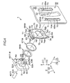
- FIG. 4 is an exploded perspective view of the tilt lock mechanism 9 on the left side Y2.
- the first moving member 43 is, for example, a sintered component, and is shaped generally like a ring as viewed in the lateral direction Y.
- the first moving member 43 integrally includes a first pressing portion 51, a second pressing portion 52, and a boss portion 53.
- the first pressing portion 51 of the first moving member 43 is shaped like a plate that is thin in the lateral direction Y.
- the first pressing portion 51 is shaped generally like a rectangle as viewed in the lateral direction Y
- an insertion hole 51A is formed which penetrates the first pressing portion 51 in the lateral direction Y.
- a right side surface of the first pressing portion 51 is referred to as a first pressing surface 54.
- the second pressing portion 52 of the first moving member 43 is shaped like a plate that is thin in the lateral direction Y.
- the second pressing portion 52 protrudes from the first pressing surface 54 of the first pressing portion 51 toward the right side Y1.
- the second pressing portion 52 is shaped generally like a circle as viewed from the right side Y1.
- flat surfaces 52A are formed which are parallel to each other and flat along the axial direction X and the lateral direction Y.
- a right side surface of the second pressing portion 52 is referred to as a second pressing surface 55.
- the second pressing surface 55 is shaped generally like a semicircular arc, and two second pressing surfaces 55 are provided such that they are separated from each other in the axial direction X.
- the second pressing surfaces 55 protrude in the opposite outward directions in the axial direction X.
- the insertion hole 51A also penetrates the second pressing portion 52 in the lateral direction Y.
- the boss portion 53 is shaped generally like a rectangle as viewed in the lateral direction Y and protrudes from an area between the second pressing surfaces 55 toward the right side Y1. Opposite surfaces 53A of the boss portion 53 in the axial direction X extend in the tilt direction C along edges of the tilt groove 32 extending in the tilt direction C.
- the flat surface 52A of the second pressing portion 52 on the upper side Z1 is flush with an upper end surface of the boss portion 53.
- the flat surface 52A of the second pressing portion 52 on the lower side Z2 is flush with a lower end surface of the boss portion 53.
- the upper end surface and the lower end surface of the boss portion 53 are considered to be part of the flat surfaces 52A.
- the insertion hole 51A in the first pressing portion 51 also penetrates the boss portion 53 in the lateral direction Y. Substantially in the center of the boss portion 53 in the up-down direction Z, a pair of cutouts 53B is formed which is formed by cutting out the boss portion 53 from the right side Y1. The cutouts 53B are separated from each other in the axial direction X. The cutouts 53B communicate with the insertion hole 51A.
- the boss portion 53 is divided into two portions, namely, an upper side portion and a lower side portion.
- the left end of the rotating shaft 40 is inserted through the insertion hole 51A in the first moving member 43.
- the first moving member 43 is located on the right side Y1 of the cam 42 and is adjacent to the cam 42.
- cam protrusions 56 are formed on a right side surface of the cam 42 and a left side surface of the first pressing portion 51 of the first moving member 43. The cam protrusions 56 on the cam 42 can move onto the respective cam protrusions 56 of the first moving member 43.
- the boss portion 53 of the first moving member 43 is inserted through the tilt groove 32 on the left side Y2.
- the surfaces 53A of the boss portion 53 function as what is called width across flats and extend along the edges of the tilt groove 32 extending in the tilt direction C (the opposite edges in the axial direction X).
- the tilt groove 32 prevents the first moving member 43 from running idle.
- the pair of second pressing surfaces 55 of the second pressing portion 52 of the first moving member 43 is located on the left side Y2 of the left side surface (peripheral portion of the tilt groove 32) of the side plate 30 of the upper bracket 6 on the left side Y2, and is in contact with the left side surface.
- a nut 44 is attached in the threaded groove 40C of the rotating shaft 40. Between the nut 44 and the side plate 30 on the right side, the second moving member 45, the needle roller bearing 46, and the thrust washer 47 are disposed in this order from the lefts side Y2.
- the second moving member 45 is substantially the same as the first moving member 43 in shape, and the shape of the second moving member 45 is equal to a shape resulting from inversion of the first moving member 43 across the reference plane 3D. Specifically, the portions of the second moving member 45 are obtained such that the portions of the first moving member 43 are moved to the opposite side across the reference plane 3D and that the first and second moving members 43 and 45 are mirror images of each other. However, unlike the first moving member 43, the second moving member 45 has no cam protrusions 56 formed thereon.
- the rotating shaft 40 is inserted through the second moving member 45, the needle roller bearing 46, and the thrust washer 47.
- the boss portion 53 of the second moving member 45 is inserted through the tilt groove 32 on the right side Y1.
- the rotating shaft 40 supports the second moving member 45 such that the second moving member 45 is relatively rotatable with the rotating shaft 40.
- the surfaces 53A of the boss portion 53 function as width across flats and extend along the edges of the tilt groove 32 extending in the tilt direction C.
- the pair of second pressing surfaces 55 of the second moving member 45 is located on the right side Y1 of the right side surface (peripheral portion of the tilt groove 32) of the side plate 30 of the upper bracket 6 on the right side Y1, and is in contact with the right side surface.
- the rotating shaft 40 can move in the tilt direction C in each of the tilt grooves 32 of the upper bracket 6 but does not move relative to the shaft insertion holes 35 in the axial direction X or the tilt direction C.
- the driver moves the steering member 11 in the tilt direction C for the tilt adjustment
- the column jacket 4 as a whole is tilted relative to the upper bracket 6 as described above.
- the rotating shaft 40 inserted through the shaft insertion holes 35 moves in the tilt direction C along with the column jacket 4.
- the tilt adjustment of the steering member 11 is performed within a range where the boss portions 53 of the first moving member 43 and the second moving member 45 can move in the tilt grooves 32.
- the cam 42 rotates, and the cam protrusions 56 formed on the cam 42 and the cam protrusions 56 formed on the first moving member 43 move onto each other. Consequently, the first moving member 43 moves toward the right side Y1, that is, toward the upper bracket 6, along the central axis 40A of the rotating shaft 40.
- the second pressing surfaces 55 of the first moving member 43 are pressed against the left side surface of the side plate 30 on the left side Y2.
- the second moving member 45 moves in such a way as to be attracted to the left side Y2, that is, toward the upper bracket 6, and the second pressing surfaces 55 are pressed against the right side surface of the side plate 30 on the right side Y1.
- the first moving member 43 and the second pressing surfaces 55 of the second moving member 45 are positioned close to the insertion holes 51A through which the rotating shaft 40 is inserted (see FIG. 4 ).
- the first moving member 43 and the second moving member 45 can be restrained from being deformed by the reaction force to which the first moving member 43 and the second moving member 45 are subjected as a result of tightening of the side plates 30.
- the first moving member 43 and the second moving member 45 move in the lateral direction Y relative to the side plates 30 of the upper bracket 6 in accordance with an operation of the operation member 41. Consequently, the side plates 30 are tightened between the first moving member 43 and the second moving member 45 from the both sides in the lateral direction Y.
- the support portions 34 of the lower jacket 23 are sandwiched between the side plates 30 from the both sides in the lateral direction Y to cause a frictional force between each of the side plates 30 and the corresponding support portion 34.
- the frictional force locks the column jacket 4 in a position, and the steering member 11 is also locked at a position resulting from the tilt adjustment and cannot move in the tilt direction C.
- the pair of support portions 34 of the lower jacket 23 is sandwiched between the side plates 30 to reduce the distance between the support portions 34. This narrows an inner peripheral portion of the lower jacket 23 to bring the lower jacket 23 into pressure contact with the upper jacket 22 in the lower jacket 23. As a result, a frictional force is caused between the upper jacket 22 and the lower jacket 23. The friction between the upper jacket 22 and the lower jacket 23 locks the upper jacket 22 in a position.
- the steering member 11 is also locked at a position resulting from the telescopic adjustment and cannot move in the axial direction X.
- a state of the steering system 1 when the position of the steering member 11 is fixed in the tilt direction C and the axial direction X is referred to as a locked state.
- the state of the steering system 1 when the steering member 11 is not locked in a position in the tilt direction C and the axial direction X is referred to as a released state.
- the telescopic lock mechanism 8 is a mechanism configured to firmly lock the upper jacket 22 in a position with respect to the lower jacket 23 in the axial direction X through meshing of the teeth and to release the upper jacket 22.
- the telescopic lock mechanism 8 includes a tubular lock member 57, a transmission member 58, and a lock plate 59 extending in the axial direction X.
- the tilt lock mechanism 9 is a mechanism configured to lock the column jacket 4 in a position in the tilt direction C and to release the column jacket 4.
- the tilt lock mechanism 9 is provided around each of the side plates 30.
- the tilt lock mechanism 9 on the left side Y2 includes the above-described first moving member 43, tooth engagement portions 65 formed in the side plate 30 on the left side Y2, a tooth member 66, an elastic member 67, and a spacer 68.
- a pair of the tooth engagement portions 65 is formed integrally with the side plate 30 on the left side Y2 by extrusion or the like, and protrudes from a left side surface of the side plate 30 on the left side Y2 toward the left side Y2.
- the tooth engagement portions 65 are positioned on the back of the side plate 30 on the left side Y2.
- the tooth engagement portions 65 are provided such that the tilt groove 32 is sandwiched between the tooth engagement portions 65 from both in the axial direction X.
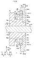
- FIG. 5 is a sectional view taken along line V-V in FIG. 3 .
- FIG. 6 is a sectional view taken along line VI-VI in FIG. 5 .
- the tooth engagement portions 65 each integrally have a holding portion 70 shaped generally like a rectangle and extending along the tilt direction C and a first tooth rows 71 protruding from the holding portion 70 toward the tilt groove 32 in the axial direction X.
- an engaged surface 70A is formed which is flat in the axial direction X and the tilt direction C.
- Each of the first tooth rows 71 includes a plurality of first teeth 72 arranged at regular intervals along the tilt direction C.
- Each of the first teeth 72 has a tip facing the tilt groove 32 in the axial direction X. More specifically, the first teeth 72 in the first tooth row 71 on the rear side X1 have tips facing the front side X2.
- a left end surface of each of the first teeth 72 is a part of the engaged surface of the holding portion 70.
- the tooth engagement portions 65 are each formed by, for example, extrusion toward the left side Y2.
- a recess 65A slightly smaller than the tooth engagement portion 65 is formed in a right side surface of the side plate 30 on the left side Y2.
- the tooth member 66 is obtained by processing a single metal plate with a plate thickness t using press molding or the like, and is rigid.
- the tooth member 66 integrally includes a body portion 74, a pair of second tooth rows 75, a pair of ribs 76 and a pair of spring portions 77.
- the body portion 74 is shaped generally like a rectangle that is thin in the lateral direction Y and that extends in the tilt direction C.
- a right side surface of the body portion 74 is hereinafter referred to as an engaging surface 74A.
- the engaging surface 74A is flat in the axial direction X and the tilt direction C.
- a through-hole 78 is formed which penetrates the body portion 74 in the lateral direction Y.
- the through-hole 78 is generally circular as viewed in the lateral direction Y.
- Opposite ends in the up-down direction Z located in peripheral edges 78A defining the through-hole 78 in the body portion 74 are parallel to the flat surfaces 52A of the second pressing portion 52 of the first moving member 43.
- the peripheral edges 78A substantially align with an outer peripheral surface of the second pressing portion 52 of the first moving member 43 as viewed from the left side Y2 (see FIG. 5 ).
- the second tooth rows 75 protrude outward from both edges of the body portion 74 in the axial direction X.
- Each of the second tooth rows 75 includes a plurality of second teeth 82 arranged at regular intervals along the tilt direction C.
- a left end surface of each of the second teeth 82 is a part of a left end surface of the body portion 74.
- a right end surface of each of the second teeth 82 is a part of a right end surface of the engaging surface 74A of the body portion 74 (see FIG. 6 ).
- the ribs 76 are formed by folding both ends of the main body portion 74 in the up-down direction Z, to the left side Y2.
- the ribs 76 are thin in the up-down direction Z and extend along the axial direction X.
- the ribs 76 reinforce the body portion 74.
- the spring portions 77 protrude in the same direction in the lateral direction Y (toward the right side Y1) from a rear end 76A of the rib 76 on the upper side Z1 and from a front end 76B of the rib 76 on the lower side Z2 so as to extend away from the body portion 74 in the up-down direction Z.
- Each of the spring portions 77 has a support portion 83 protruding from the rib 76 so as to extend away from the body portion 74 in the up-down direction Z and a deformation portion 84 that is supported by the support portion 83 and that can be elastically deformed in the lateral direction Y.
- the support portion 83 is shaped like a plate that is thin in the lateral direction Y.
- the support portion 83 of the spring portion 77 on the upper side Z1 extends from the rear end 76A of the rib 76 on the upper side Z1 toward the upper side Z1.
- the support portion 83 of the spring portion 77 on the lower side Z2 extends from the front end 76B of the rib 76 on the lower side Z2 toward the lower side Z2.
- the deformation portion 84 of the spring portion 77 on the upper side Z1 is thin in the lateral direction Y and extends from a front end of the support portion 83 on the upper side Z1 toward the front side X2 and the right side Y1.
- the deformation portion 84 of the spring portion 77 on the lower side Z2 is thin in the lateral direction Y and extends from a rear end of the support portion 83 on the lower side Z2 toward the rear side X1 and the right side Y1.
- a contact portion 85 is formed.
- the portion is formed by pushing the tip portion toward the right side Y1 by press molding.
- the contact portion 85 is shaped generally like a circle as viewed from the right side Y1.
- the tooth member 66 is disposed between the first pressing portion 51 of the first moving member 43 and the side plate 30 on the left side Y2 so as to be on the left side Y2 of the side plate 30 on the left side Y2.
- the first pressing portion 51 of the first moving member 43 is disposed on the opposite side (on the left side Y2) of the tooth member 66 from the side plate 30 on the left side Y2.
- the second pressing portion 52 of the first moving member 43 is inserted through the through-hole 78 of the tooth member 66.
- the tooth member 66 can move in the lateral direction Y.
- the peripheral edges 78A of the body portion 74 defining the through-hole 78 substantially aligns with the outer peripheral surface of the second pressing portion 52 of the first moving member 43 as viewed from the right side Y1 (see FIG. 5 ).
- rotation of the tooth member 66 relative to the first moving member 43 is regulated.
- the engaging surface 74A of the body portion 74 provided with the second tooth rows 75 faces the engaged surface 70A of the first tooth row 71 in the lateral direction Y (see FIG. 4 ).
- the second tooth rows 75 are positioned to overlap the respective first tooth rows 71 of the side plate 30 in the axial direction X.
- each spring portion 77 of the tooth member 66 is located on the left side Y2 of the left side surface of the side plate 30 on the left side Y2 (see FIG. 4 ).
- the deformation portion 84 of each spring portion 77 has been deformed in the lateral direction Y to exert a force that allows the deformation portion 84 to return to a non-deformed state, that is, a restoration force.
- the elastic member 67 is, for example, a disc spring.
- the elastic member 67 is shaped generally like a ring that fans out in a radial direction of the rotating shaft 40 toward the right side Y1.
- a section of the elastic member 67 taken along a surface orthogonal to a circumferential direction of the rotating shaft 40 is shaped like a truncated chevron inclined counterclockwise at an angle of 90°.
- the elastic member 67 can exert a restoration force F that allows the elastic member 67 to return to the non-deformed state when compressed in the lateral direction Y.
- FIG. 7 is a graph illustrating the relation between the compression distance P and the restoration force F of the elastic member 67.
- the restoration force F gradually increases as the distance by which the elastic member 67 is compressed in the lateral direction Y, that is, the compression distance P increases.
- the compression distance P reaches a first compression distance P1
- the restoration force F of the elastic member 67 reaches a load F1.
- the restoration force F remains constant and equal to the load F1 until the compression distance P reaches a second compression distance P2.
- the compression distance P exceeds the second compression distance P2
- the restoration force F starts to increase again.
- the restoration force F of the elastic member 67 is higher than the restoration force of the deformation portions 84 of the tooth member 66. In this manner, the elastic member 67 enables a constant restoration force F to be exerted within the predetermined range between the second compression distance P2 and the first compression distance P1.
- the load F1 at which the restoration force F remains constant and the first and second compression distances P1 and P2 of the compression distance P can be adjusted by, for example, regulating the warpage or plate thickness of the elastic member 67.
- the elastic member 67 is a disc spring but may be a leaf spring or any other spring.
- the elastic member 67 should be any elastically deformable member that exerts a constant restoration force F within the predetermined range of the compression distance P.
- the second pressing portion 52 of the first moving member 43 is inserted through a hollow portion of the elastic member 67 from the right side Y1.
- the elastic member 67 is disposed between the tooth member 66 and the first pressing portion 51 of the first moving member 43.
- a left end inner peripheral edge of the elastic member 67 extends along a portion of the outer peripheral surface of the second pressing portion 52 that is other than the flat surfaces 52A (see also FIG. 5 ).
- a right end of the elastic member 67 is in contact with a left end surface of the body portion 74 of the tooth member 66. Apart of the right end of the elastic member 67 is in contact with some of the second teeth 82 of the second tooth row 75 (see FIG. 5 ).
- the spacer 68 is, for example, a sintered component and is shaped like a ring that is thin in the lateral direction Y (see FIG. 4 ).
- the spacer 68 is inserted on the second pressing portion 52 of the first moving member 43 from the right side Y1.
- An inner peripheral surface of the spacer 68 extends along portions of the outer peripheral surface of the second pressing portion 52 that are other than the flat surface 52A.
- the spacer 68 is disposed between the first pressing portion 51 and the elastic member 67.
- a left side surface of the spacer 68 is in surface contact with the first pressing surface 54 of the first pressing portion 51 of the first moving member 43 from the right side Y1.
- a right side surface of the spacer 68 is entirely in contact with a left end of the elastic member 67 from the left side Y2.
- the tooth member 66, the elastic member 67, and the spacer 68 are inserted on the second pressing portion 52 of the first moving member 43 through which the rotating shaft 40 is inserted, and thus move in the tilt direction C in the tilt groove 32 during the tilt adjustment.
- the rotating shaft 40 inserted through the shaft insertion holes 35 moves in the tilt direction C along with the column jacket 4. Consequently, the tooth member 66, the elastic member 67, and the spacer 68 move in the tilt direction C along with the column jacket 4.
- the tilt lock mechanism 9 on the right side Y1 includes the second moving member 45, the tooth engagement portion 65 provided on the side plate 30 on the right side Y1, the tooth member 66, the elastic member 67, and the spacer 68.
- the tooth engagement portion 65, the tooth member 66, the elastic member 67, and the spacer 68 of the tilt lock mechanism 9 on the right side Y1 are obtained such that the tooth engagement portion 65, the tooth member 66, the elastic member 67, and the spacer 68 in the tilt lock mechanism 9 on the left side Y2 are moved to the opposite side across the reference plane 3D and that the components of the tilt lock mechanism 9 on the right side Y1 and those of the tilt lock mechanism 9 on the left side Y2 are mirror images of each other.
- the second moving member 45 is disposed on the opposite side (on the right side Y1 of the tooth member 66 from the side plate 30 on the right side Y1.
- the first teeth 72 of each first tooth row 71 and the second teeth 82 of each second tooth row 75 are alternately arranged in the tilt direction C.
- the first tooth rows 71 and the second tooth rows 75 mesh with each other.
- the tooth members 66 are fixed to the lower jacket 23 via the first moving member 43, the second moving member 45, and the rotating shaft 40.
- the first tooth rows 71 are fixed to the upper bracket 6 fixed to the vehicle body 2 (see FIG. 3 ).
- movement of the column jacket 4 around the central shaft 5C of the lower bracket 5 in the tilt direction C is regulated (see FIG. 1 ).
- the upper jacket 22 is more firmly locked in a position in the tilt direction C as a result of the friction between the lower jacket 23 and the pair of side plates 30 of the upper bracket 6 and the meshing between the first tooth rows 71 and the second tooth rows 75.
- the position of the first moving member 43 in the lateral direction Y at this time is referred to as a locked position.
- the tilt lock mechanism 9 is a tooth lock mechanism in which the teeth mesh with one another to firmly hold the column jacket 4 in position.
- the deformation portions 84 of the spring portions 77 of the tooth member 66 are pressed against the side plate 30 and elastically deformed in the lateral direction Y.
- the tooth member 66 as a whole is biased toward the elastic member 67 by the restoration force of the deformation portions 84.
- the elastic member 67 is compressed in the lateral direction Y to exert the restoration force F equal to the load F1.
- the tilt lock mechanism 9 will be described which is performed to switch the steering system 1 from the locked state to the released state.
- the operation of the tilt lock mechanism 9 on the left side Y2 will be focused on.
- the operation of the tilt lock mechanism 9 on the right side Y1 is similar to the operation of the tilt lock mechanism 9 on the left side Y2 because the operation of the tilt lock mechanism 9 on the right side Y1 is the mirror-reversed operation of the tilt lock mechanism 9 on the left side Y2, and will thus not be described below.
- FIG. 8 is also referred to which depicts the released state of the steering system 1.
- the compression distance P of the elastic member 67 in the lateral direction Y gradually decreases in conjunction with movement of the first moving member 43 toward the left side Y2. Before the steering system 1 is completely set to the released state, the elastic member 67 is set to an uncompressed state.
- the spacer 68 is biased toward the left side Y2 by the restoration force F of the elastic member 67.
- the spacer 68 moves toward the left side Y2 in contact with the first pressing surface 54 of the first moving member 43 while the first moving member 43 is moving toward the left side Y2.
- the tooth member 66 As described above, since the deformation portions 84 of the spring portions 77 of the tooth member 66 are elastically deformed in the lateral direction Y, the tooth member 66 as a whole is biased toward the left side Y2 by the restoration force F of the deformation portion 84.
- the restoration force of the deformation portions 84 are negligibly small compared with the restoration force F.
- the second tooth rows 75 have moved farther toward the left side Y2 than the first tooth rows 71, and the meshing between the second tooth rows 75 and the first tooth rows 71 has been released.
- the position of the first moving member 43 in the lateral direction Y at this time is referred to as a released position.
- the frictional force caused between the side plates 30 of the upper bracket 6 and the support portions 34 of the lower jacket 23 is also eliminated in the released state.
- the lock of the steering member 11 in a position in the tilt direction C is completely released, which allows the tilt adjustment of the steering member 11.
- the operation member 41 (see FIG. 3 ) is operated to set the steering system 1 to the locked state
- the first moving member 43 moves from the released state toward the right side Y1 as described above.
- the tooth member 66 is moved toward the right side Y1 by the first pressing portion 51 of the first moving member 43 via the spacer 68 and the elastic member 67. Consequently, the second tooth rows 75 of the tooth member 66 are positioned on the right side Y1, the first tooth rows 71 and the second tooth rows 75 mesh with each other, and the engaging surface 74A of the body portion 74 of the tooth member 66 comes into contact with the left side surface of the side plate 30 on the left side Y2, as depicted in FIG. 5 and FIG. 6 .
- FIG. 9 is a graph illustrating the relation between the moving distance of the first moving member 43 and the operating force S exerted on the operation member 41.
- an operating force S exerted on the operation member 41 does not substantially increase before the second tooth rows 75 of the tooth member 66 mesh with the first tooth rows 71.
- the first moving member 43 moves toward the right side Y1 while compressing the elastic member 67 in the lateral direction Y.
- the restoration force F (see FIG. 7 ) of the elastic member 67 in the lateral direction Y gradually increases. Consequently, a force transmitted from the elastic member 67 to the operation member 41 via the first moving member 43 also gradually increases.
- the force needed to operate the operation member 41 that is, the operating force S, gradually increases.
- Reference character D1 is used to denote the moving distance of the first moving member 43 from the released position to the position where the operating force S starts to increase.
- Reference character D2 is used to denote the moving distance of the first moving member 43 from the released position to the locked position.
- the restoration force F of the elastic member 67 becomes constant and equal to the load F1 (see FIG. 7 ).
- a difference between the moving distance D1 and the moving distance D2 is smaller than the difference between the first compression distance P1 and the second compression distance P2 of the compression distance P of the elastic member 67.
- the restoration force F of the elastic member 67 in the lateral direction Y is constant within a predetermined range where the first moving member 43 moves toward the right side Y1 between the position where the compression distance P reaches the first compression distance P1 and the locked position.
- the restoration force F acts on the operation member 41 as a constant reaction force. Therefore, while the first moving member 43 is moving within the predetermined range, the operating force S exerted to operate the operation member 41 remains constant and equal to a load S 1.
- the spacer 68 is biased toward the left side Y2 by the restoration force F of the elastic member 67.
- the spacer 68 moves toward the right side Y1 in contact with the first pressing surface 54 of the first moving member 43.
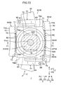
- FIG. 10 is a diagram depicting the second tooth rows 75 having moved onto the first tooth rows 71 in FIG. 5 .
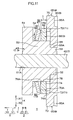
- FIG. 11 is a sectional view taken along line XI-XI in FIG. 10 .
- the first moving member 43 moves the tooth member 66 toward the right side Y1 via the spacer 68 and the elastic member 67.
- the second tooth rows 75 have moved onto the first tooth row 71, and thus, the distance between the tooth member 66 and the first moving member 43 in the half locked state is shorter than that in a non-half-locked state by a value equal to the plate thickness t of the body portion 74 of the tooth member 66.
- the frictional force caused by the positioning mechanism 7 locks the column jacket 4 in a position, and the steering member 11 is locked at the position resulting from the tilt adjustment and cannot move in the tilt direction C, as in the locked state.
- the positioning mechanism 7 and the tilt lock mechanisms 9 allow the column jacket 4 to be locked in a position regardless of whether or not the first tooth rows 71 and the second tooth rows 75 mesh with each other.
- the tilt adjustment can be achieved in a stepless manner within the range where the first moving member 43 and the second moving member 45 can move in the tilt grooves 32.
- the elastic member 67 starts to be compressed when the first moving member 43 moves in the half locked state toward the right side Y1.
- Reference character D3 is used to denote the moving distance of the first moving member 43 from the released position to a position where, in the half locked state, the elastic member 67 starts to be compressed.
- the distance between the tooth member and the moving member in the half locked state is shorter than that in the non-half-locked state by the value equal to the plate thickness t of the body portion 74 of the tooth member 66 (see FIG. 11 ).
- the moving distance D3 is shorter than the moving distance D1 of the first moving member 43 from the released position to a position where the operating force S starts to be increased in the case where half lock is not performed.
- the difference between the moving distance D1 and the moving distance D3 corresponds to the plate thickness t of the body portion 74 of the tooth member 66.
- a difference between the moving distance D2 and the moving distance D4 is smaller than the difference between the first compression distance P1 and the second compression distance P2 of the compression distance P of the elastic member 67.
- the restoration force F of the elastic member 67 in the lateral direction Y is constant within a predetermined range where the first moving member 43 moves toward the right side Y1 between a position away from the released position by the distance D4 toward the right side Y1 and the locked position. Consequently, while the first moving member 43 is moving within the predetermined range, the operating force S exerted to operate the operation member 41 remains constant and equal to the load S1.
- the tooth member 66 comes into contact with the side plate 30 on the left side Y2 earlier than usual, which accordingly increases the compression distance P of the elastic member 67. If the elastic member 67 is omitted unlike in the present embodiment, the operating force S continues to increase instead of remaining constant as illustrated by a long dashed double-short dashed line. Thus, although not illustrated in FIG. 9 , an operating force S larger than the load S1 is needed when the first moving member 43 reaches the locked position.
- the restoration force F exerted by the elastic member 67 remains constant and equal to the load F1. Therefore, the operating force S exerted on the operation member 41 remains constant and equal to the load S1 regardless of whether or not the first tooth rows 71 and the second tooth rows 75 mesh properly with each other. the operating force S can thus be stabilized.
- the normal locked state and the half locked state are the same in the manner of rising of the operating force S with respect to the moving distance of the first moving member 43 and in the maximum value (load S1) of the operating force S. Consequently, the feeling experienced by the user of the vehicle in operating the operation member 41 is substantially the same in the locked state and in the half locked state.
- the dimensions or the like of the elastic member 67 are adjusted to allow a constant restoration force F to be exerted while the first moving member 43 is moving within the predetermined range.
- FIG. 12A is a diagram schematically illustrating the positional relation between the elastic member 67 and the tooth member 66.
- FIG. 12B is a diagram illustrating that the position of the elastic member 67 has been displaced from the position in FIG. 12A .
- the tooth member 66 is rigid and has the reinforcing ribs 76, which enhance the rigidity of the tooth member 66. Consequently, the tooth member 66 is difficult to deflect wherever the tooth member 66 is subjected to the restoration force F of the elastic member 67 in the tilt direction C and the axial direction X.
- the restoration force F of the elastic member 67 to which the tooth member 66 is subjected remains constant even if the center of gravity A1 of the elastic member 67 overlaps the center of gravity A2 of the rotating shaft 40 in the axial direction X and the tilt direction C as viewed in the lateral direction Y as illustrated in FIG.
- the operating force S exerted on the operation member 41 can be restrained from being varied by the reaction force resulting from the deflection of the tooth member 66. This also allows the operating force S exerted on the operation member 41 to be stabilized.
- the tooth member 66 need not be deflected.
- the operating force S exerted on the operation member 41 remains constant.
- the size of the elastic member 67 can be freely selected.
- a secondary impact occurs in which the driver collides against the steering member 11.
- the steering member 11 is subjected to impact in the axial direction X and the tilt direction C by a reaction force resulting from deployment of an air bag or the driver's collision against the airbag.
- the telescopic lock mechanism 8 and the tilt lock mechanisms 9 reliably maintain the position of the column jacket 4 in the axial direction X and the tilt direction C. Therefore, the position of the airbag during the secondary impact can be appropriately maintained.
- the column jacket 4 acts to pivot in the tilt direction C.
- the first teeth 72 of the first tooth rows 71 are arranged alternately with the second teeth 82 of the second tooth rows 75 in the tilt direction C.
- the tooth member 66 with the second tooth rows 75 are subjected to the restoration force F of the elastic member 67 compressed in the lateral direction Y, and thus, the tooth member 66 moves toward the upper bracket 6. This causes the first tooth rows 71 and the second tooth rows 75 to mesh with each other. Consequently, even in the half lock, the column jacket 4 can be prevented from being pivoted in the tilt direction C during the secondary impact.
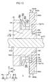
- FIG. 13 is a diagram illustrating the variation of the present invention applied in FIG. 11 .
- the elastic member 67 in the present embodiment is inverted in the lateral direction Y.
- the elastic member 67 in the variation is shaped generally like a ring that fans out in the radial direction of the rotating shaft 40 toward the left side Y2.
- a section of the elastic member 67 taken along a surface orthogonal to the circumferential direction of the rotating shaft 40 is shaped like a truncated chevron inclined clockwise at an angle of 90°.
- the tilt lock mechanism 9 may be provided on one of the right side Y1 or the left side Y2 of the upper bracket 6.
- the ribs 76 of the tooth member 66 may be provided separately from the body portion 74 of the tooth member 66.
- the tooth engagement portions 65 may be formed separately from the side plates 30.
- the recesses 65A are not formed in each side plates 30, and the holding portions 70 and the first tooth rows 71 of the tooth engagement portions 65 are solid, unlike in the present embodiment.
- the tooth engagement portions 65 are attached to the side plate 30 by welding or the like.
- the steering system 1 is not limited to a manual steering system in which the operation of the steering member 11 is not assisted.
- the steering system 1 may be a column-assist electric power steering system 1 in which the operation of the steering member 11 is assisted by an electric motor.
- the tilt lock mechanism 9 is also applicable to a steering system with no telescopic lock mechanism unlike the present embodiment.
- the tilt lock mechanism 9 is also applicable to a capsule steering system 1 with a capsule (not depicted in the drawings) that couples the coupling plate 31 of the upper bracket 6 to the vehicle body 2 (see FIG. 1 ), unlike the present embodiment.
- the ribs 76 may be omitted if the tooth member 66 can be made sufficiently rigid without the ribs 76.
Landscapes
- Engineering & Computer Science (AREA)
- Chemical & Material Sciences (AREA)
- Combustion & Propulsion (AREA)
- Transportation (AREA)
- Mechanical Engineering (AREA)
- Steering Controls (AREA)
Abstract
Description
- The invention relates to a steering system.
- A steering column described in
US Patent Application No. 2009-0013817 (US 2009/0013817 A ) includes an adjustment portion that positions the steering column and a holding portion that does not move in a direction in which the position of the steering column is adjusted (adjustment direction). The holding portion is provided with tooth portions arranged in the adjustment direction. A tooth plate of an elastomer is inserted through a clamp bolt penetrating the adjustment portion and the holding portion. The tooth plate has tooth portions arranged in the adjustment direction. - Operating an operation member attached to the clamp bolt allows a pressing member through which the clamp bolt is inserted to be moved toward the holding portion. Moving the pressing member toward the holding portion causes the tooth plate to be pressed by the pressing member to move toward the holding portion. At this time, the tooth portions of the tooth plate are each placed between the tooth portions of the holding portion to engage the tooth portions of the holding portion with the tooth portions of the tooth plate.
- The steering column described in
US 2009/0013817 A needs to operate the operation member with a predetermined force (operating force) during locking. When the operation member is locked, unlike the case where the tooth portions of the tooth plate mesh properly with the tooth portions of the holding portion, when the tooth portions of the tooth plate fail to mesh properly with the tooth portions of the holding portion and move onto the tooth portions of the holding portion to deflect the tooth plate, the reaction force of the deflected tooth plate acts on the operation member via the pressing member to increase the operating force. Thus, the operating force exerted on the operating member may vary between the case of the proper meshing between the tooth portions of the tooth plate and the tooth portions of the holding portion and the case of the failure in the proper meshing, which leads to an unstable operating force. - An object of the present invention is to provide a steering system that allows an operating force exerted on an operation member to be stabilized.
- According to an aspect of the present invention, a steering system includes: a column jacket that holds a steering shaft with a steering member coupled to one end of the steering shaft and that is movable in a tilt direction intersecting an axial direction of the steering shaft in an up-down direction in order to position the steering member in the tilt direction; a bracket that has a first tooth row including a plurality of first teeth arranged along the tilt direction, and that is fixed to a vehicle body to support the column jacket; an operation member that is operated for the positioning; a rigid tooth member that is provided adjacent to the bracket in a direction orthogonal to both the axial direction and the tilt direction and that is movable in the tilt direction along with the column jacket and movable in the orthogonal direction; a second tooth row that is provided on a surface of the tooth member facing the first tooth row in the orthogonal direction and that includes a plurality of second teeth arranged along the tilt direction, the second tooth row meshing with the first tooth row when the first teeth and the second teeth are alternately arranged in the tilt direction; a moving member that is disposed on the opposite side of the tooth member from the bracket in the orthogonal direction and that is movable in the orthogonal direction in accordance with an operation of the operation member; and an elastic member disposed between the tooth member and the moving member, and within a predetermined range where the moving member moves toward the bracket, exerting a constant restoration force while being compressed in the orthogonal direction
- In the steering system according to the aspect, the bracket supporting the column jacket has the first tooth row including the first teeth arranged along the tilt direction intersecting the axial direction of the steering shaft to which the steering member is coupled, in the up-down direction. The tooth member moving in the tilt direction along with the column jacket during positioning of the steering member is provided adjacent to the bracket in the direction orthogonal to both the axial direction of the steering shaft and the tilt direction.
- The second tooth row that includes the plurality of second teeth arranged along the tilt direction is provided on the surface of the tooth member facing the first tooth row in the orthogonal direction. The moving member is disposed on the opposite side of the tooth member from the bracket in the orthogonal direction. The elastic member is disposed between the tooth member and the moving member.
- While the moving member is moving toward the bracket within the predetermined range in the orthogonal direction in accordance with the operation of the operation member, the elastic member moves the tooth member toward the bracket in the orthogonal direction while being compressed between the tooth member and the moving member. Normally, the first teeth and the second teeth are alternately arranged in the tilt direction to mesh the first tooth row with the second tooth row. Thus, the steering member is locked in a position in the tilt direction. While the moving member is moving within the predetermined range, the elastic member exerts the constant restoration force, which acts on the operation member as a constant reaction force. Therefore, while the moving member is moving within the predetermined range, the operating force exerted to operate the operation member is kept constant.
- On the other hand, depending on the position of the column jacket resulting from the positioning of the steering member, the first tooth row and the second tooth row may fail to mesh properly with each other, and the second tooth row moves onto the first tooth row in the orthogonal direction. In this case, the tooth member comes into contact with the bracket earlier than usual, which accordingly increases the degree to which the elastic member is compressed in the orthogonal direction (compression distance). However, even in such a case, the moving member moves within the predetermined range, the elastic member exerts the constant restoration force as is the case with the above-described normal case. Therefore, regardless of whether or not the first tooth row and the second tooth row mesh properly with each other, the operating force exerted on the operation member is kept constant and can be stabilized.
- The tooth member is rigid and thus difficult to deflect. Consequently, the operating force exerted on the operation member can be restrained from being varied by a reaction force resulting from the deflection of the tooth member. This also allows the operating force exerted on the operation member to be stabilized.
- In the steering system according to the aspect, the tooth member may have a reinforcing rib.
- In the steering system according to the aspect, the tooth member has a reinforcing rib and is thus rigid and difficult to deflect. Consequently, the operating force exerted on the operation member can be restrained from being varied by the reaction force resulting from the deflection of the tooth member. This also allows the operating force exerted on the operation member to be stabilized.
- According to the aspect, the steering system may be configured such that, when the first tooth row and the second tooth row are in mesh with each other, the elastic member is in contact with at least a part of the second tooth row.
- In the steering system according to the aspect, the elastic member may be a disc spring.
- In the steering system according to the aspect, when the elastic member is a disc spring, the dimensions or the like of the elastic member are adjusted to allow the constant restoration force to be exerted while the moving member is moving within the predetermined range.
- The foregoing and further features and advantages of the invention will become apparent from the following description of example embodiments with reference to the accompanying drawings, wherein like numerals are used to represent like elements and wherein:
-
FIG. 1 is a side view depicting a general configuration of asteering system 1 according to an embodiment of the present invention; -
FIG. 2 is a perspective view of thesteering system 1; -
FIG. 3 is a sectional view taken along line III-III inFIG. 1 ; -
FIG. 4 is an exploded sectional view of atilt lock mechanism 9 on a left side Y2; -
FIG. 5 is a sectional view taken along line V-V inFIG. 3 ; -
FIG. 6 is a sectional view taken along line VI-VI inFIG. 5 ; -
FIG. 7 is a graph illustrating the relation between a compression distance P and a restoration force F of anelastic member 67; -
FIG. 8 is a diagram illustrating a released state of thesteering system 1 inFIG. 6 ; -
FIG. 9 is a graph illustrating the relation between a moving distance of a first movingmember 43 and an operating force S exerted on anoperation member 41; -
FIG. 10 is a diagram depictingsecond tooth rows 75 having moved ontofirst tooth rows 71 inFIG. 5 ; -
FIG. 11 is a sectional view taken along line XI-XI inFIG. 10 ; -
FIG. 12A is a diagram schematically illustrating the positional relation between theelastic member 67 and atooth member 66; -
FIG. 12B is a diagram illustrating that the position of theelastic member 67 has been displaced from the position inFIG. 12A ; and -
FIG. 13 is a diagram illustrating a variation of the present invention applied inFIG. 11 . - An embodiment of the present invention will be described below in detail with reference to the attached drawings.
-
FIG. 1 is a side view depicting a general configuration of asteering system 1 according to an embodiment of the present invention. InFIG. 1 , the left of the drawing plane corresponds to a front of avehicle body 2 to which thesteering system 1 is attached. The right of the drawing plane corresponds to a rear of thevehicle body 2. The upper side of the drawing plane corresponds to an upper side of thevehicle body 2. The lower side of the drawing plane corresponds to a lower side of thevehicle body 2.FIG. 2 is a perspective view of thesteering system 1. - As seen in
FIG. 1 , thesteering system 1 mainly includes asteering shaft 3, acolumn jacket 4, alower bracket 5, and an upper bracket 6 (bracket), apositioning mechanism 7, atelescopic lock mechanism 8, and a pair of tilt lock mechanisms 9 (seeFIG. 2 ). - A steering
member 11 is coupled to afirst end 3A of thesteering shaft 3 that is a rear end thereof. Asecond end 3B of thesteering shaft 3 that is a front end thereof is coupled to apinion shaft 16 of asteering operation mechanism 15 via auniversal joint 12, anintermediate shaft 13, and a universal joint 14 in order. - The
steering operation mechanism 15 includes a rack and pinion mechanism. When rotation of thesteering shaft 3 is transferred to thesteering operation mechanism 15, thesteering operation mechanism 15 steers steered wheels such as tires not depicted in the drawings, in accordance with the rotating distance of thesteering shaft 3. - The steering
shaft 3 extends in a front-rear direction of thevehicle body 2. A direction in which thesteering shaft 3 extends is hereinafter referred to as an axial direction X. The axial direction X is inclined to a horizontal direction such that thesecond end 3B is lower than thefirst end 3A. The rear side in the axial direction X is denoted by reference character X1. The front side in the axial direction X is denoted by reference character X2. - Among directions orthogonal to the axial direction X, a direction perpendicular to the drawing plane of
FIG. 1 is referred to as a lateral direction Y, and a direction extending generally in an up-down direction inFIG. 1 is referred to as an up-down direction Z. In the lateral direction Y, a side facing away from the viewer inFIG. 1 is a right side Y1, and a side facing the viewer inFIG. 1 is a left side Y2. In the up-down direction Z, an upper side is denoted by reference character Z1, and a lower side is denoted by reference character Z2. - In the figures other than
FIG. 1 , the same reference characters as those inFIG. 1 are used for directions corresponding to the axial direction X, the rear side X1, the front side X2, the lateral direction Y, the right side Y1, the left side Y2, the up-down direction Z, the upper side Z1, and the lower side Z2. - The steering
shaft 3 has anupper shaft 20 that is at least partly cylindrical and a columnarlower shaft 21. Theupper shaft 20 is disposed on the rear side X1 with respect to thelower shaft 21 so as to be coaxial with thelower shaft 21. - A
rear end 20A of theupper shaft 20 corresponds to thefirst end 3A of thesteering shaft 3. The steeringmember 11 is coupled to therear end 20A of theupper shaft 20. - A
front end 21A of thelower shaft 21 corresponds to thesecond end 3B of thesteering shaft 3. A rear end of thelower shaft 21 is inserted into afront end 20B of theupper shaft 20 from the front side X2. - The
lower shaft 21 is fitted into theupper shaft 20 by spline fitting or serration fitting and coupled to thefront end 20B of theupper shaft 20. Thus, theupper shaft 20 and thelower shaft 21 can rotate integrally and move relative to each other along the axial direction X. Movement of theupper shaft 20 with respect to thelower shaft 21 in the axial direction X enables thesteering shaft 3 to be extended and contracted in the axial direction X. - The
column jacket 4 is generally a hollow member extending in the axial direction X. Thecolumn jacket 4 houses and holds thesteering shaft 3. Thecolumn jacket 4 has anupper jacket 22 and alower jacket 23 extending in the axial direction X. Theupper jacket 22 is positioned on the rear side X1 with respect to thelower jacket 23. Theupper jacket 22 is fitted in thelower jacket 23. Specifically, afront end 22A of theupper jacket 22 is inserted from the rear side X1 into arear end 23A of thelower jacket 23. In this state, theupper jacket 22 can move with respect to thelower jacket 23 in the axial direction X. This movement enables thecolumn jacket 4 as a whole to be extended and contacted along the axial direction X. - The
column jacket 4 is coupled to thesteering shaft 3 by abearing 24 and abearing 25. Thus, thecolumn jacket 4 supports thesteering shaft 3 such that thesteering shaft 3 is rotatable. - Specifically, a rear end of the
upper jacket 22 is coupled to theupper shaft 20 by thebearing 24. Consequently, theupper jacket 22 supports theupper shaft 20 such that theupper shaft 20 is rotatable. A front end of thelower jacket 23 is coupled to thelower shaft 21 by thebearing 25. Consequently, thelower jacket 23 supports thelower shaft 21 such that thelower shaft 21 is rotatable. Thus, a set of theupper shaft 20 and theupper jacket 22 can move with respect to a set of thelower shaft 21 and thelower jacket 23 in the axial direction X. This enables thecolumn jacket 4 to be extended and contracted along with thesteering shaft 3. - In this case, extension and contraction of the
steering shaft 3 and thecolumn jacket 4 is referred to as telescopic motion, and adjustment based on the telescopic motion, in other words, the positioning of the steeringmember 11 in the axial direction X based on the telescopic motion, is referred to as telescopic adjustment. - The
lower bracket 5 supports a front side X2 portion of thelower jacket 23 to couple thesteering system 1 to thevehicle body 2. - The
lower bracket 5 includes a pair ofmovable brackets 5A (see alsoFIG. 2 ) fixed to thelower jacket 23, a fixedbracket 5B fixed to thevehicle body 2, and acentral shaft 5C extending in the lateral direction Y. - The
movable brackets 5A are pivotally supported by the fixedbracket 5B via thecentral shaft 5C. Thus, thecolumn jacket 4 as a whole can pivot up and down around thecentral shaft 5C along with thesteering shaft 3. The pivoting in this case is referred to as tilting, and a general up-down direction around thecentral shaft 5C is referred to as a tilt direction C. The tilt direction intersects the axial direction X in the up-down direction. The tilt direction C is orthogonal to the lateral direction Y. Positioning of the steeringmember 11 based on the tilting is referred to as tilt adjustment. - The
upper bracket 6 supports a rear side X1 portion of thelower jacket 23 to couple thesteering system 1 to thevehicle body 2. - As seen in
FIG. 2 , theupper bracket 6 is shaped like a groove that is open downward and formed laterally symmetrically with respect to thecolumn jacket 4 so as to be generally inverted U-shaped as viewed in the axial direction X. More specifically, theupper bracket 6 integrally includes a pair ofside plates 30 and acoupling plate 31. Theside plates 30 are thin in the lateral direction Y and are across thecolumn jacket 4 from each other. Thecoupling plate 31 is coupled to upper ends of therespective side plates 30 and is thin in the up-down direction Z. - In the pair of
side plates 30, atilt groove 32 is formed in eachside plate 30 such that thetilt grooves 32 are located at the same position as viewed in the lateral direction Y. Thetilt groove 32 extends in the tilt direction C. Thecoupling plate 31, for example, has portions extending outward from therespective side plates 30 in the lateral direction Y. Theupper bracket 6 as a whole is fixed to the vehicle body 2 (seeFIG. 1 ) with for example, bolts inserted through the extending portions and not depicted in the drawings. - In an upper side Z1 portion of the
lower jacket 23, aslit 33 is formed which extends all along thelower jacket 23 in the axial direction and penetrates thelower jacket 23 in the up-down direction Z. At therear end 23A of thelower jacket 23, a pair ofsupport portions 34 is integrally provided which extends in the upper side Z1 direction and defines theslit 33 in the lateral direction Y. Each of thesupport portions 34 is shaped generally like a rectangular parallelepiped extending in the axial direction X and the up-down direction Z. -
FIG. 3 is a sectional view taken along line III-III inFIG. 1 . InFIG. 3 , a plane extending in the up-down direction Z through acentral axis 3C of thesteering shaft 3 is referred to as areference plane 3D. - As seen in
FIG. 3 , in each of thesupport portions 34, ashaft insertion hole 35 is formed which penetrates thecorresponding support portion 34. Theshaft insertion hole 35 is shaped generally like a circle as viewed in the lateral direction Y. The shaft insertion holes 35 in thesupport portions 34 are located at the same position as viewed in the lateral direction Y The shaft insertion holes 35 in thesupport portions 34 overlap parts of thetilt grooves 32 in theside plates 30 of theupper bracket 6 as viewed in the lateral direction Y - The
positioning mechanism 7 is a mechanism that enables the tilt adjustment and the telescopic adjustment of the steering member 11 (seeFIG. 1 ) and that locks the steeringmember 11, on which the tilt adjustment and the telescopic adjustment have been executed, in a position. - The
positioning mechanism 7 includes arotating shaft 40, anoperation member 41, acam 42, a first movingmember 43, anut 44, a second movingmember 45, aneedle roller bearing 46, and athrust washer 47. - The rotating
shaft 40 is made of metal and shaped like a rod having acentral axis 40A extending in the lateral direction Y. The rotatingshaft 40 is slightly smaller than the shaft insertion holes 35 as viewed in the lateral direction Y. The rotatingshaft 40 is inserted through areas where the shaft insertion holes 35 and thetilt grooves 32 overlap as viewed in the lateral direction Y. The rotatingshaft 40 can rotate about thecentral axis 40A in the shaft insertion holes 35 and thetilt grooves 32. The rotatingshaft 40 is supported by theside plates 30 of theupper bracket 6. The rotatingshaft 40 is positioned on the upper side Z1 with respect to thesteering shaft 3. - A left end of the
rotating shaft 40 that is a first end thereof is positioned on the left side Y2 with respect to theside plate 30 provided on the left side Y2. A right end of therotating shaft 40 that is a second end thereof is positioned on the right side Y1 with respect to theside plate 30 of theupper bracket 6 that is provided on the right side Y1. - At the left end of the
rotating shaft 40, ahead portion 40B is provided which has a larger diameter than the other parts of therotating shaft 40. In an outer periphery of the right end of therotating shaft 40, a threaded groove 40C is formed. - The
operation member 41 is a lever or the like that can be gripped. In abase end 41A of theoperation member 41 that is a first end thereof in a longitudinal direction of theoperation member 41, aninsertion hole 41 B is formed which penetrates theoperation member 41 in the lateral direction Y. The rotatingshaft 40 is inserted through theinsertion hole 41B. A driver can grip a grippingportion 41C of theoperation member 41 that is a second end thereof in the longitudinal direction. The rotatingshaft 40 is pivoted along with theoperation member 41 in accordance with an operation of theoperation member 41. - The
cam 42 integrally includes anannular plate portion 42A and atubular boss portion 42B. Theannular plate portion 42A is located on the right side Y1 of thebase end 41A of theoperation member 41 and is adjacent to thebase end 41A. Thetubular boss portion 42B extends from theplate portion 42A toward the left side Y2. The rotatingshaft 40 is inserted through a space defined by inner peripheral surfaces of theplate portion 42A and theboss portion 42B. Theboss portion 42B is inserted through theinsertion hole 41B in theoperation member 41. Thecam 42 rotates integrally with the rotatingshaft 40. -
FIG. 4 is an exploded perspective view of thetilt lock mechanism 9 on the left side Y2. - As seen in
FIG. 4 , the first movingmember 43 is, for example, a sintered component, and is shaped generally like a ring as viewed in the lateral direction Y. The first movingmember 43 integrally includes a firstpressing portion 51, a secondpressing portion 52, and aboss portion 53. - The first
pressing portion 51 of the first movingmember 43 is shaped like a plate that is thin in the lateral direction Y. The firstpressing portion 51 is shaped generally like a rectangle as viewed in the lateral direction Y In the first pressingportion 51, aninsertion hole 51A is formed which penetrates the first pressingportion 51 in the lateral direction Y. A right side surface of the first pressingportion 51 is referred to as a firstpressing surface 54. - The second
pressing portion 52 of the first movingmember 43 is shaped like a plate that is thin in the lateral direction Y. The secondpressing portion 52 protrudes from the first pressingsurface 54 of the first pressingportion 51 toward the right side Y1. The secondpressing portion 52 is shaped generally like a circle as viewed from the right side Y1. On both sides of the secondpressing portion 52 in the up-down direction,flat surfaces 52A are formed which are parallel to each other and flat along the axial direction X and the lateral direction Y. - A right side surface of the second
pressing portion 52 is referred to as a secondpressing surface 55. To be exact, the secondpressing surface 55 is shaped generally like a semicircular arc, and two secondpressing surfaces 55 are provided such that they are separated from each other in the axial direction X. The secondpressing surfaces 55 protrude in the opposite outward directions in the axial direction X. Theinsertion hole 51A also penetrates the secondpressing portion 52 in the lateral direction Y. - The
boss portion 53 is shaped generally like a rectangle as viewed in the lateral direction Y and protrudes from an area between the secondpressing surfaces 55 toward the right side Y1.Opposite surfaces 53A of theboss portion 53 in the axial direction X extend in the tilt direction C along edges of thetilt groove 32 extending in the tilt direction C. Theflat surface 52A of the secondpressing portion 52 on the upper side Z1 is flush with an upper end surface of theboss portion 53. Theflat surface 52A of the secondpressing portion 52 on the lower side Z2 is flush with a lower end surface of theboss portion 53. The upper end surface and the lower end surface of theboss portion 53 are considered to be part of theflat surfaces 52A. Theinsertion hole 51A in the first pressingportion 51 also penetrates theboss portion 53 in the lateral direction Y. Substantially in the center of theboss portion 53 in the up-down direction Z, a pair ofcutouts 53B is formed which is formed by cutting out theboss portion 53 from the right side Y1. Thecutouts 53B are separated from each other in the axial direction X. Thecutouts 53B communicate with theinsertion hole 51A. Thus, theboss portion 53 is divided into two portions, namely, an upper side portion and a lower side portion. - As seen in
FIG. 3 , the left end of therotating shaft 40 is inserted through theinsertion hole 51A in the first movingmember 43. The first movingmember 43 is located on the right side Y1 of thecam 42 and is adjacent to thecam 42. On a right side surface of thecam 42 and a left side surface of the first pressingportion 51 of the first movingmember 43,cam protrusions 56 are formed. The cam protrusions 56 on thecam 42 can move onto therespective cam protrusions 56 of the first movingmember 43. - The
boss portion 53 of the first movingmember 43 is inserted through thetilt groove 32 on the left side Y2. As described above, thesurfaces 53A of theboss portion 53 function as what is called width across flats and extend along the edges of thetilt groove 32 extending in the tilt direction C (the opposite edges in the axial direction X). Thus, thetilt groove 32 prevents the first movingmember 43 from running idle. - The pair of second
pressing surfaces 55 of the secondpressing portion 52 of the first movingmember 43 is located on the left side Y2 of the left side surface (peripheral portion of the tilt groove 32) of theside plate 30 of theupper bracket 6 on the left side Y2, and is in contact with the left side surface. - A
nut 44 is attached in the threaded groove 40C of therotating shaft 40. Between thenut 44 and theside plate 30 on the right side, the second movingmember 45, theneedle roller bearing 46, and thethrust washer 47 are disposed in this order from the lefts side Y2. - The second moving
member 45 is substantially the same as the first movingmember 43 in shape, and the shape of the second movingmember 45 is equal to a shape resulting from inversion of the first movingmember 43 across thereference plane 3D. Specifically, the portions of the second movingmember 45 are obtained such that the portions of the first movingmember 43 are moved to the opposite side across thereference plane 3D and that the first and second movingmembers member 43, the second movingmember 45 has nocam protrusions 56 formed thereon. - The rotating
shaft 40 is inserted through the second movingmember 45, theneedle roller bearing 46, and thethrust washer 47. - The
boss portion 53 of the second movingmember 45 is inserted through thetilt groove 32 on the right side Y1. The rotatingshaft 40 supports the second movingmember 45 such that the second movingmember 45 is relatively rotatable with the rotatingshaft 40. As described above, thesurfaces 53A of theboss portion 53 function as width across flats and extend along the edges of thetilt groove 32 extending in the tilt direction C. Thus, the second movingmember 45 is prevented from rotating in thetilt groove 32 on the right side Y1. The pair of secondpressing surfaces 55 of the second movingmember 45 is located on the right side Y1 of the right side surface (peripheral portion of the tilt groove 32) of theside plate 30 of theupper bracket 6 on the right side Y1, and is in contact with the right side surface. - The rotating
shaft 40 can move in the tilt direction C in each of thetilt grooves 32 of theupper bracket 6 but does not move relative to the shaft insertion holes 35 in the axial direction X or the tilt direction C. When the driver moves the steeringmember 11 in the tilt direction C for the tilt adjustment, thecolumn jacket 4 as a whole is tilted relative to theupper bracket 6 as described above. At this time, the rotatingshaft 40 inserted through the shaft insertion holes 35 moves in the tilt direction C along with thecolumn jacket 4. The tilt adjustment of the steeringmember 11 is performed within a range where theboss portions 53 of the first movingmember 43 and the second movingmember 45 can move in thetilt grooves 32. - When a user such as the driver pivots the
operation member 41 after performing the telescopic adjustment or the tilt adjustment, thecam 42 rotates, and the cam protrusions 56 formed on thecam 42 and the cam protrusions 56 formed on the first movingmember 43 move onto each other. Consequently, the first movingmember 43 moves toward the right side Y1, that is, toward theupper bracket 6, along thecentral axis 40A of therotating shaft 40. The secondpressing surfaces 55 of the first movingmember 43 are pressed against the left side surface of theside plate 30 on the left side Y2. In conjunction with this, the second movingmember 45 moves in such a way as to be attracted to the left side Y2, that is, toward theupper bracket 6, and the secondpressing surfaces 55 are pressed against the right side surface of theside plate 30 on the right side Y1. - The first moving
member 43 and the secondpressing surfaces 55 of the second movingmember 45 are positioned close to the insertion holes 51A through which therotating shaft 40 is inserted (seeFIG. 4 ). Thus, the first movingmember 43 and the second movingmember 45 can be restrained from being deformed by the reaction force to which the first movingmember 43 and the second movingmember 45 are subjected as a result of tightening of theside plates 30. - As described above, the first moving
member 43 and the second movingmember 45 move in the lateral direction Y relative to theside plates 30 of theupper bracket 6 in accordance with an operation of theoperation member 41. Consequently, theside plates 30 are tightened between the first movingmember 43 and the second movingmember 45 from the both sides in the lateral direction Y. Thus, thesupport portions 34 of thelower jacket 23 are sandwiched between theside plates 30 from the both sides in the lateral direction Y to cause a frictional force between each of theside plates 30 and thecorresponding support portion 34. The frictional force locks thecolumn jacket 4 in a position, and the steeringmember 11 is also locked at a position resulting from the tilt adjustment and cannot move in the tilt direction C. - Furthermore, the pair of
support portions 34 of thelower jacket 23 is sandwiched between theside plates 30 to reduce the distance between thesupport portions 34. This narrows an inner peripheral portion of thelower jacket 23 to bring thelower jacket 23 into pressure contact with theupper jacket 22 in thelower jacket 23. As a result, a frictional force is caused between theupper jacket 22 and thelower jacket 23. The friction between theupper jacket 22 and thelower jacket 23 locks theupper jacket 22 in a position. The steeringmember 11 is also locked at a position resulting from the telescopic adjustment and cannot move in the axial direction X. - As described above, a state of the
steering system 1 when the position of the steeringmember 11 is fixed in the tilt direction C and the axial direction X is referred to as a locked state. - In the
steering system 1 in the locked state, pivoting theoperation member 41 in a direction opposite to the above-described direction rotates thecam 42 with respect to the first movingmember 43. The first movingmember 43 moves toward the left side Y2 along the axial direction of therotating shaft 40. The second movingmember 45 moves toward the right side Y1 along the axial direction. Theside plates 30 are thus not tightened between the first movingmember 43 and the second movingmember 45. This eliminates the frictional force between eachside plate 30 and thecorresponding support portion 34 and the frictional force between thelower jacket 23 and theupper jacket 22, allowing the steeringmember 11 to move in the axial direction X and the tilt direction C. As described above, operating theoperation member 41 enables the telescopic adjustment or the tilt adjustment of the steeringmember 11 again. In other words, theoperation member 41 is operated for the telescopic adjustment or the tilt adjustment. - Thus, the state of the
steering system 1 when the steeringmember 11 is not locked in a position in the tilt direction C and the axial direction X is referred to as a released state. - As seen in
FIG. 1 , thetelescopic lock mechanism 8 is a mechanism configured to firmly lock theupper jacket 22 in a position with respect to thelower jacket 23 in the axial direction X through meshing of the teeth and to release theupper jacket 22. Thetelescopic lock mechanism 8 includes atubular lock member 57, atransmission member 58, and alock plate 59 extending in the axial direction X. - As seen in
FIG. 3 , thetilt lock mechanism 9 is a mechanism configured to lock thecolumn jacket 4 in a position in the tilt direction C and to release thecolumn jacket 4. - The
tilt lock mechanism 9 is provided around each of theside plates 30. Thetilt lock mechanism 9 on the left side Y2 includes the above-described first movingmember 43,tooth engagement portions 65 formed in theside plate 30 on the left side Y2, atooth member 66, anelastic member 67, and aspacer 68. - As seen in
FIG. 4 , a pair of thetooth engagement portions 65 is formed integrally with theside plate 30 on the left side Y2 by extrusion or the like, and protrudes from a left side surface of theside plate 30 on the left side Y2 toward the left side Y2. Thus, thetooth engagement portions 65 are positioned on the back of theside plate 30 on the left side Y2. Thetooth engagement portions 65 are provided such that thetilt groove 32 is sandwiched between thetooth engagement portions 65 from both in the axial direction X. -
FIG. 5 is a sectional view taken along line V-V inFIG. 3 .FIG. 6 is a sectional view taken along line VI-VI inFIG. 5 . - As seen in
FIG. 5 , thetooth engagement portions 65 each integrally have a holdingportion 70 shaped generally like a rectangle and extending along the tilt direction C and afirst tooth rows 71 protruding from the holdingportion 70 toward thetilt groove 32 in the axial direction X. - At a left end of the holding
portion 70, an engagedsurface 70A is formed which is flat in the axial direction X and the tilt direction C. - The
first tooth row 71 on the rear side X1 and thefirst tooth row 71 on the front side X2 face each other in the axial direction. Each of thefirst tooth rows 71 includes a plurality offirst teeth 72 arranged at regular intervals along the tilt direction C. Each of thefirst teeth 72 has a tip facing thetilt groove 32 in the axial direction X. More specifically, thefirst teeth 72 in thefirst tooth row 71 on the rear side X1 have tips facing the front side X2. Thefirst teeth 72 in thefirst tooth row 71 on the front side X2 have tips facing the rear side X1. A left end surface of each of thefirst teeth 72 is a part of the engaged surface of the holdingportion 70. - As seen in
FIG. 4 , thetooth engagement portions 65 are each formed by, for example, extrusion toward the left side Y2. Thus, arecess 65A slightly smaller than thetooth engagement portion 65 is formed in a right side surface of theside plate 30 on the left side Y2. - The
tooth member 66 is obtained by processing a single metal plate with a plate thickness t using press molding or the like, and is rigid. Thetooth member 66 integrally includes abody portion 74, a pair ofsecond tooth rows 75, a pair ofribs 76 and a pair ofspring portions 77. - The
body portion 74 is shaped generally like a rectangle that is thin in the lateral direction Y and that extends in the tilt direction C. A right side surface of thebody portion 74 is hereinafter referred to as anengaging surface 74A. Theengaging surface 74A is flat in the axial direction X and the tilt direction C. - Substantially in the center of the
body portion 74 in the axial direction X and the up-down direction Z, a through-hole 78 is formed which penetrates thebody portion 74 in the lateral direction Y. The through-hole 78 is generally circular as viewed in the lateral direction Y. Opposite ends in the up-down direction Z located inperipheral edges 78A defining the through-hole 78 in thebody portion 74 are parallel to theflat surfaces 52A of the secondpressing portion 52 of the first movingmember 43. Theperipheral edges 78A substantially align with an outer peripheral surface of the secondpressing portion 52 of the first movingmember 43 as viewed from the left side Y2 (seeFIG. 5 ). - The
second tooth rows 75 protrude outward from both edges of thebody portion 74 in the axial direction X. Each of thesecond tooth rows 75 includes a plurality ofsecond teeth 82 arranged at regular intervals along the tilt direction C. A left end surface of each of thesecond teeth 82 is a part of a left end surface of thebody portion 74. A right end surface of each of thesecond teeth 82 is a part of a right end surface of theengaging surface 74A of the body portion 74 (seeFIG. 6 ). - As seen in
FIG. 4 , theribs 76 are formed by folding both ends of themain body portion 74 in the up-down direction Z, to the left side Y2. Thus, theribs 76 are thin in the up-down direction Z and extend along the axial direction X. Theribs 76 reinforce thebody portion 74. - As seen in
FIG. 5 , thespring portions 77 protrude in the same direction in the lateral direction Y (toward the right side Y1) from arear end 76A of therib 76 on the upper side Z1 and from afront end 76B of therib 76 on the lower side Z2 so as to extend away from thebody portion 74 in the up-down direction Z. Each of thespring portions 77 has asupport portion 83 protruding from therib 76 so as to extend away from thebody portion 74 in the up-down direction Z and adeformation portion 84 that is supported by thesupport portion 83 and that can be elastically deformed in the lateral direction Y. - As seen in
FIG. 4 , thesupport portion 83 is shaped like a plate that is thin in the lateral direction Y. Thesupport portion 83 of thespring portion 77 on the upper side Z1 extends from therear end 76A of therib 76 on the upper side Z1 toward the upper side Z1. Thesupport portion 83 of thespring portion 77 on the lower side Z2 extends from thefront end 76B of therib 76 on the lower side Z2 toward the lower side Z2. - The
deformation portion 84 of thespring portion 77 on the upper side Z1 is thin in the lateral direction Y and extends from a front end of thesupport portion 83 on the upper side Z1 toward the front side X2 and the right side Y1. Thedeformation portion 84 of thespring portion 77 on the lower side Z2 is thin in the lateral direction Y and extends from a rear end of thesupport portion 83 on the lower side Z2 toward the rear side X1 and the right side Y1. - At a tip portion of each of the
deformation portions 84, acontact portion 85 is formed. The portion is formed by pushing the tip portion toward the right side Y1 by press molding. Thecontact portion 85 is shaped generally like a circle as viewed from the right side Y1. - The
tooth member 66 is disposed between the first pressingportion 51 of the first movingmember 43 and theside plate 30 on the left side Y2 so as to be on the left side Y2 of theside plate 30 on the left side Y2. In other words, the first pressingportion 51 of the first movingmember 43 is disposed on the opposite side (on the left side Y2) of thetooth member 66 from theside plate 30 on the left side Y2. - As seen in
FIG. 6 , the secondpressing portion 52 of the first movingmember 43 is inserted through the through-hole 78 of thetooth member 66. In this state, thetooth member 66 can move in the lateral direction Y. As described above, theperipheral edges 78A of thebody portion 74 defining the through-hole 78 substantially aligns with the outer peripheral surface of the secondpressing portion 52 of the first movingmember 43 as viewed from the right side Y1 (seeFIG. 5 ). Thus, rotation of thetooth member 66 relative to the first movingmember 43 is regulated. - In the
tooth member 66, the engagingsurface 74A of thebody portion 74 provided with thesecond tooth rows 75 faces the engagedsurface 70A of thefirst tooth row 71 in the lateral direction Y (seeFIG. 4 ). Thesecond tooth rows 75 are positioned to overlap the respectivefirst tooth rows 71 of theside plate 30 in the axial direction X. - The
contact portion 85 of eachspring portion 77 of thetooth member 66 is located on the left side Y2 of the left side surface of theside plate 30 on the left side Y2 (seeFIG. 4 ). In this state, thedeformation portion 84 of eachspring portion 77 has been deformed in the lateral direction Y to exert a force that allows thedeformation portion 84 to return to a non-deformed state, that is, a restoration force. - The
elastic member 67 is, for example, a disc spring. Theelastic member 67 is shaped generally like a ring that fans out in a radial direction of therotating shaft 40 toward the right side Y1. As seen inFIG. 6 , a section of theelastic member 67 taken along a surface orthogonal to a circumferential direction of therotating shaft 40 is shaped like a truncated chevron inclined counterclockwise at an angle of 90°. Theelastic member 67 can exert a restoration force F that allows theelastic member 67 to return to the non-deformed state when compressed in the lateral direction Y. -
FIG. 7 is a graph illustrating the relation between the compression distance P and the restoration force F of theelastic member 67. - As seen in
FIG. 7 , when theelastic member 67 that is not compressed in the lateral direction Y starts to be compressed in the lateral direction Y, the restoration force F gradually increases as the distance by which theelastic member 67 is compressed in the lateral direction Y, that is, the compression distance P increases. When the compression distance P reaches a first compression distance P1, the restoration force F of theelastic member 67 reaches a load F1. Even when theelastic member 67 is further compressed in the lateral direction Y, the restoration force F remains constant and equal to the load F1 until the compression distance P reaches a second compression distance P2. When the compression distance P exceeds the second compression distance P2, the restoration force F starts to increase again. The restoration force F of theelastic member 67 is higher than the restoration force of thedeformation portions 84 of thetooth member 66. In this manner, theelastic member 67 enables a constant restoration force F to be exerted within the predetermined range between the second compression distance P2 and the first compression distance P1. - When the
elastic member 67 is a disc spring, the load F1 at which the restoration force F remains constant and the first and second compression distances P1 and P2 of the compression distance P can be adjusted by, for example, regulating the warpage or plate thickness of theelastic member 67. In the present embodiment, theelastic member 67 is a disc spring but may be a leaf spring or any other spring. In short, theelastic member 67 should be any elastically deformable member that exerts a constant restoration force F within the predetermined range of the compression distance P. - As seen in
FIG. 6 , the secondpressing portion 52 of the first movingmember 43 is inserted through a hollow portion of theelastic member 67 from the right side Y1. Theelastic member 67 is disposed between thetooth member 66 and the first pressingportion 51 of the first movingmember 43. A left end inner peripheral edge of theelastic member 67 extends along a portion of the outer peripheral surface of the secondpressing portion 52 that is other than theflat surfaces 52A (see alsoFIG. 5 ). A right end of theelastic member 67 is in contact with a left end surface of thebody portion 74 of thetooth member 66. Apart of the right end of theelastic member 67 is in contact with some of thesecond teeth 82 of the second tooth row 75 (seeFIG. 5 ). - The
spacer 68 is, for example, a sintered component and is shaped like a ring that is thin in the lateral direction Y (seeFIG. 4 ). Thespacer 68 is inserted on the secondpressing portion 52 of the first movingmember 43 from the right side Y1. An inner peripheral surface of thespacer 68 extends along portions of the outer peripheral surface of the secondpressing portion 52 that are other than theflat surface 52A. Thespacer 68 is disposed between the first pressingportion 51 and theelastic member 67. A left side surface of thespacer 68 is in surface contact with the first pressingsurface 54 of the first pressingportion 51 of the first movingmember 43 from the right side Y1. A right side surface of thespacer 68 is entirely in contact with a left end of theelastic member 67 from the left side Y2. - The
tooth member 66, theelastic member 67, and thespacer 68 are inserted on the secondpressing portion 52 of the first movingmember 43 through which therotating shaft 40 is inserted, and thus move in the tilt direction C in thetilt groove 32 during the tilt adjustment. As described above, during the tilt adjustment, the rotatingshaft 40 inserted through the shaft insertion holes 35 moves in the tilt direction C along with thecolumn jacket 4. Consequently, thetooth member 66, theelastic member 67, and thespacer 68 move in the tilt direction C along with thecolumn jacket 4. - As seen in
FIG. 3 , thetilt lock mechanism 9 on the right side Y1 includes the second movingmember 45, thetooth engagement portion 65 provided on theside plate 30 on the right side Y1, thetooth member 66, theelastic member 67, and thespacer 68. Thetooth engagement portion 65, thetooth member 66, theelastic member 67, and thespacer 68 of thetilt lock mechanism 9 on the right side Y1 are obtained such that thetooth engagement portion 65, thetooth member 66, theelastic member 67, and thespacer 68 in thetilt lock mechanism 9 on the left side Y2 are moved to the opposite side across thereference plane 3D and that the components of thetilt lock mechanism 9 on the right side Y1 and those of thetilt lock mechanism 9 on the left side Y2 are mirror images of each other. In thetilt lock mechanism 9 on the right side Y1, the second movingmember 45 is disposed on the opposite side (on the right side Y1 of thetooth member 66 from theside plate 30 on the right side Y1. - As seen in
FIG. 6 , when thesteering system 1 is in the above-described locked state, in the state inFIG. 6 , thefirst teeth 72 of eachfirst tooth row 71 and thesecond teeth 82 of eachsecond tooth row 75 are alternately arranged in the tilt direction C. Thus, thefirst tooth rows 71 and thesecond tooth rows 75 mesh with each other. Thetooth members 66 are fixed to thelower jacket 23 via the first movingmember 43, the second movingmember 45, and therotating shaft 40. Thefirst tooth rows 71 are fixed to theupper bracket 6 fixed to the vehicle body 2 (seeFIG. 3 ). Thus, movement of thecolumn jacket 4 around thecentral shaft 5C of thelower bracket 5 in the tilt direction C is regulated (seeFIG. 1 ). Therefore, in the locked state, theupper jacket 22 is more firmly locked in a position in the tilt direction C as a result of the friction between thelower jacket 23 and the pair ofside plates 30 of theupper bracket 6 and the meshing between thefirst tooth rows 71 and thesecond tooth rows 75. The position of the first movingmember 43 in the lateral direction Y at this time is referred to as a locked position. As described above, thetilt lock mechanism 9 is a tooth lock mechanism in which the teeth mesh with one another to firmly hold thecolumn jacket 4 in position. - In the locked state, the
deformation portions 84 of thespring portions 77 of thetooth member 66 are pressed against theside plate 30 and elastically deformed in the lateral direction Y. Thus, thetooth member 66 as a whole is biased toward theelastic member 67 by the restoration force of thedeformation portions 84. Theelastic member 67 is compressed in the lateral direction Y to exert the restoration force F equal to the load F1. - Now, an operation of the
tilt lock mechanism 9 will be described which is performed to switch thesteering system 1 from the locked state to the released state. In the description below, the operation of thetilt lock mechanism 9 on the left side Y2 will be focused on. The operation of thetilt lock mechanism 9 on the right side Y1 is similar to the operation of thetilt lock mechanism 9 on the left side Y2 because the operation of thetilt lock mechanism 9 on the right side Y1 is the mirror-reversed operation of thetilt lock mechanism 9 on the left side Y2, and will thus not be described below. - For convenience of description,
FIG. 8 is also referred to which depicts the released state of thesteering system 1. - When the operation member 41 (see
FIG. 3 ) is operated to set thesteering system 1 to the released state, the first movingmember 43 moves from the locked position toward the left side Y2. - The compression distance P of the
elastic member 67 in the lateral direction Y gradually decreases in conjunction with movement of the first movingmember 43 toward the left side Y2. Before thesteering system 1 is completely set to the released state, theelastic member 67 is set to an uncompressed state. - The
spacer 68 is biased toward the left side Y2 by the restoration force F of theelastic member 67. Thus, thespacer 68 moves toward the left side Y2 in contact with the first pressingsurface 54 of the first movingmember 43 while the first movingmember 43 is moving toward the left side Y2. - As described above, since the
deformation portions 84 of thespring portions 77 of thetooth member 66 are elastically deformed in the lateral direction Y, thetooth member 66 as a whole is biased toward the left side Y2 by the restoration force F of thedeformation portion 84. The restoration force of thedeformation portions 84 are negligibly small compared with the restoration force F. Thus, when theelastic member 67 is set to the uncompressed state while thesteering system 1 is changing from the lock state to the released state, thetooth member 66 starts to move toward the left side Y2 due to the restoration force F of thedeformation portions 84. In conjunction with this, thesecond tooth rows 75 of thetooth member 66 start to move toward the left side Y2. In the released state, thesecond tooth rows 75 have moved farther toward the left side Y2 than thefirst tooth rows 71, and the meshing between thesecond tooth rows 75 and thefirst tooth rows 71 has been released. The position of the first movingmember 43 in the lateral direction Y at this time is referred to as a released position. - As described above, the frictional force caused between the
side plates 30 of theupper bracket 6 and thesupport portions 34 of thelower jacket 23 is also eliminated in the released state. Thus, in the released state, the lock of the steeringmember 11 in a position in the tilt direction C is completely released, which allows the tilt adjustment of the steeringmember 11. - Now, an operation of the
tilt lock mechanism 9 on the left side Y2 will be described which is performed when thesteering system 1 changes from the released state to the locked state. This operation is obtained by reversing the operation performed when thesteering system 1 changes from the locked state to the released state. Since the restoration force of thedeformation portions 84 are negligibly small compared with the restoration force F as described above, the restoration force of thedeformation portions 84 will not be taken into account below. - When the operation member 41 (see
FIG. 3 ) is operated to set thesteering system 1 to the locked state, the first movingmember 43 moves from the released state toward the right side Y1 as described above. Thetooth member 66 is moved toward the right side Y1 by the first pressingportion 51 of the first movingmember 43 via thespacer 68 and theelastic member 67. Consequently, thesecond tooth rows 75 of thetooth member 66 are positioned on the right side Y1, thefirst tooth rows 71 and thesecond tooth rows 75 mesh with each other, and theengaging surface 74A of thebody portion 74 of thetooth member 66 comes into contact with the left side surface of theside plate 30 on the left side Y2, as depicted inFIG. 5 andFIG. 6 . -
FIG. 9 is a graph illustrating the relation between the moving distance of the first movingmember 43 and the operating force S exerted on theoperation member 41. - As seen in
FIG. 9 , an operating force S exerted on theoperation member 41 does not substantially increase before thesecond tooth rows 75 of thetooth member 66 mesh with thefirst tooth rows 71. - After the
second tooth rows 75 of thetooth member 66 mesh with thefirst tooth rows 71, the first movingmember 43 moves toward the right side Y1 while compressing theelastic member 67 in the lateral direction Y. When the first movingmember 43 starts to compress theelastic member 67, the restoration force F (seeFIG. 7 ) of theelastic member 67 in the lateral direction Y gradually increases. Consequently, a force transmitted from theelastic member 67 to theoperation member 41 via the first movingmember 43 also gradually increases. Thus, the force needed to operate theoperation member 41, that is, the operating force S, gradually increases. Reference character D1 is used to denote the moving distance of the first movingmember 43 from the released position to the position where the operating force S starts to increase. Reference character D2 is used to denote the moving distance of the first movingmember 43 from the released position to the locked position. - As described above, when the compression distance P of the
elastic member 67 reaches the first compression distance P1, the restoration force F of theelastic member 67 becomes constant and equal to the load F1 (seeFIG. 7 ). A difference between the moving distance D1 and the moving distance D2 is smaller than the difference between the first compression distance P1 and the second compression distance P2 of the compression distance P of theelastic member 67. Thus, the restoration force F of theelastic member 67 in the lateral direction Y is constant within a predetermined range where the first movingmember 43 moves toward the right side Y1 between the position where the compression distance P reaches the first compression distance P1 and the locked position. The restoration force F acts on theoperation member 41 as a constant reaction force. Therefore, while the first movingmember 43 is moving within the predetermined range, the operating force S exerted to operate theoperation member 41 remains constant and equal to aload S 1. - The
spacer 68 is biased toward the left side Y2 by the restoration force F of theelastic member 67. Thus, while the first movingmember 43 is moving toward the right side Y1, thespacer 68 moves toward the right side Y1 in contact with the first pressingsurface 54 of the first movingmember 43. - Now, a case is assumed where, after performing the tilt adjustment, the user operates the
operation member 41 with thefirst teeth 72 overlapping thesecond teeth 82 in the tilt direction C. -
FIG. 10 is a diagram depicting thesecond tooth rows 75 having moved onto thefirst tooth rows 71 inFIG. 5 .FIG. 11 is a sectional view taken along line XI-XI inFIG. 10 . - As seen in
FIG. 10 , in this case as described above, the first movingmember 43 moves thetooth member 66 toward the right side Y1 via thespacer 68 and theelastic member 67. - As seen in
FIG. 11 , since thefirst teeth 72 does not overlap thesecond teeth 82 in the tilt direction C, the engagingsurface 74A of thesecond tooth row 75 and the engagedsurface 70A of thefirst tooth rows 71 come into contact with each other in the lateral direction Y. Consequently, what is called half lock occurs in which thefirst tooth rows 71 and thesecond tooth row 75 fail to mesh with each other and thesecond tooth rows 75 move onto thefirst tooth rows 71. A state of thesteering system 1 where the half lock occurs is referred to as a half locked state. In the half locked state, thesecond tooth rows 75 have moved onto thefirst tooth row 71, and thus, the distance between thetooth member 66 and the first movingmember 43 in the half locked state is shorter than that in a non-half-locked state by a value equal to the plate thickness t of thebody portion 74 of thetooth member 66. - In the half locked state, the frictional force caused by the positioning mechanism 7 (see
FIG. 1 ) locks thecolumn jacket 4 in a position, and the steeringmember 11 is locked at the position resulting from the tilt adjustment and cannot move in the tilt direction C, as in the locked state. - As seen in
FIG. 3 , thepositioning mechanism 7 and thetilt lock mechanisms 9 allow thecolumn jacket 4 to be locked in a position regardless of whether or not thefirst tooth rows 71 and thesecond tooth rows 75 mesh with each other. In other words, the tilt adjustment can be achieved in a stepless manner within the range where the first movingmember 43 and the second movingmember 45 can move in thetilt grooves 32. - Now, an operation of the
tilt lock mechanism 9 on the left side Y2 will be described which is performed when thesteering system 1 changes from the released state to the half locked state. - As illustrated in a graph of a long dashed short dashed line in
FIG. 9 , theelastic member 67 starts to be compressed when the first movingmember 43 moves in the half locked state toward the right side Y1. Reference character D3 is used to denote the moving distance of the first movingmember 43 from the released position to a position where, in the half locked state, theelastic member 67 starts to be compressed. - As described above, the distance between the tooth member and the moving member in the half locked state is shorter than that in the non-half-locked state by the value equal to the plate thickness t of the
body portion 74 of the tooth member 66 (seeFIG. 11 ). Thus, the moving distance D3 is shorter than the moving distance D1 of the first movingmember 43 from the released position to a position where the operating force S starts to be increased in the case where half lock is not performed. The difference between the moving distance D1 and the moving distance D3 corresponds to the plate thickness t of thebody portion 74 of thetooth member 66. - Subsequently, when the first moving
member 43 starts to compress theelastic member 67, the restoration force F of theelastic member 67 in the lateral direction Y gradually increases, and thus the operating force S exerted on theoperation member 41 gradually increases. - As described above, when the compression distance P of the
elastic member 67 reaches the first compression distance P1, the restoration force F of theelastic member 67 becomes constant and equal to the load F1 (seeFIG. 7 ). Thus, the operating force S exerted on theoperation member 41 becomes constant and equal to the load S1. Reference character D4 is used to denote the distance the first movingmember 43 moves from the released position until the operating force S becomes constant in the half lock state. - A difference between the moving distance D2 and the moving distance D4 is smaller than the difference between the first compression distance P1 and the second compression distance P2 of the compression distance P of the
elastic member 67. Thus, the restoration force F of theelastic member 67 in the lateral direction Y is constant within a predetermined range where the first movingmember 43 moves toward the right side Y1 between a position away from the released position by the distance D4 toward the right side Y1 and the locked position. Consequently, while the first movingmember 43 is moving within the predetermined range, the operating force S exerted to operate theoperation member 41 remains constant and equal to the load S1. - In the half locked state, the
tooth member 66 comes into contact with theside plate 30 on the left side Y2 earlier than usual, which accordingly increases the compression distance P of theelastic member 67. If theelastic member 67 is omitted unlike in the present embodiment, the operating force S continues to increase instead of remaining constant as illustrated by a long dashed double-short dashed line. Thus, although not illustrated inFIG. 9 , an operating force S larger than the load S1 is needed when the first movingmember 43 reaches the locked position. - However, the restoration force F exerted by the
elastic member 67 remains constant and equal to the load F1. Therefore, the operating force S exerted on theoperation member 41 remains constant and equal to the load S1 regardless of whether or not thefirst tooth rows 71 and thesecond tooth rows 75 mesh properly with each other. the operating force S can thus be stabilized. - Furthermore, the normal locked state and the half locked state are the same in the manner of rising of the operating force S with respect to the moving distance of the first moving
member 43 and in the maximum value (load S1) of the operating force S. Consequently, the feeling experienced by the user of the vehicle in operating theoperation member 41 is substantially the same in the locked state and in the half locked state. - When the
elastic member 67 is a disc spring as in the present embodiment, the dimensions or the like of theelastic member 67 are adjusted to allow a constant restoration force F to be exerted while the first movingmember 43 is moving within the predetermined range. -
FIG. 12A is a diagram schematically illustrating the positional relation between theelastic member 67 and thetooth member 66.FIG. 12B is a diagram illustrating that the position of theelastic member 67 has been displaced from the position inFIG. 12A . - The
tooth member 66 is rigid and has the reinforcingribs 76, which enhance the rigidity of thetooth member 66. Consequently, thetooth member 66 is difficult to deflect wherever thetooth member 66 is subjected to the restoration force F of theelastic member 67 in the tilt direction C and the axial direction X. Thus, the restoration force F of theelastic member 67 to which thetooth member 66 is subjected remains constant even if the center of gravity A1 of theelastic member 67 overlaps the center of gravity A2 of therotating shaft 40 in the axial direction X and the tilt direction C as viewed in the lateral direction Y as illustrated inFIG. 12A or the center of gravity A1 and the center of gravity A2 are misaligned in the axial direction X and the tilt direction C. Therefore, the operating force S exerted on theoperation member 41 can be restrained from being varied by the reaction force resulting from the deflection of thetooth member 66. This also allows the operating force S exerted on theoperation member 41 to be stabilized. - In the half locked state, the
tooth member 66 need not be deflected. Thus, even when a part of the right end of theelastic member 67 is in contact with a part of thesecond tooth row 75 as depicted inFIG. 12A and FIG. 12B , the operating force S exerted on theoperation member 41 remains constant. - Since a part of the right end of the
elastic member 67 may come into abutting contact with some of thesecond teeth 82 of thesecond tooth row 75, the size of theelastic member 67 can be freely selected. - As seen in
FIG. 1 , at the time of a vehicle collision, what is called a secondary impact occurs in which the driver collides against the steeringmember 11. In the secondary impact, the steeringmember 11 is subjected to impact in the axial direction X and the tilt direction C by a reaction force resulting from deployment of an air bag or the driver's collision against the airbag. In this case, it is difficult to maintain the position of thecolumn jacket 4 using only the frictional force caused by thepositioning mechanism 7. Consequently, appropriately maintaining the position of the airbag during the secondary collision is difficult. - However, in the
steering system 1 in the present embodiment, thetelescopic lock mechanism 8 and thetilt lock mechanisms 9 reliably maintain the position of thecolumn jacket 4 in the axial direction X and the tilt direction C. Therefore, the position of the airbag during the secondary impact can be appropriately maintained. - In the half locked state, the position of the
column jacket 4 is maintained using only the frictional force caused by thepositioning mechanism 7. Thus, if a secondary impact occurs, thecolumn jacket 4 acts to pivot in the tilt direction C. In this case, when thecolumn jacket 4 is pivoted in the tilt direction C by a distance equal to the half of the pitch of thefirst tooth rows 71 and thesecond tooth rows 75, thefirst teeth 72 of thefirst tooth rows 71 are arranged alternately with thesecond teeth 82 of thesecond tooth rows 75 in the tilt direction C. Thetooth member 66 with thesecond tooth rows 75 are subjected to the restoration force F of theelastic member 67 compressed in the lateral direction Y, and thus, thetooth member 66 moves toward theupper bracket 6. This causes thefirst tooth rows 71 and thesecond tooth rows 75 to mesh with each other. Consequently, even in the half lock, thecolumn jacket 4 can be prevented from being pivoted in the tilt direction C during the secondary impact. - Now, a variation of the present invention will be described.
-
FIG. 13 is a diagram illustrating the variation of the present invention applied inFIG. 11 . - As seen in
FIG. 13 , in the variation, theelastic member 67 in the present embodiment is inverted in the lateral direction Y. - More specifically, the
elastic member 67 in the variation is shaped generally like a ring that fans out in the radial direction of therotating shaft 40 toward the left side Y2. A section of theelastic member 67 taken along a surface orthogonal to the circumferential direction of therotating shaft 40 is shaped like a truncated chevron inclined clockwise at an angle of 90°. - The present invention is not limited to the above-described embodiment, and various changes may be made to the embodiment.
- For example, unlike in the present embodiment, the
tilt lock mechanism 9 may be provided on one of the right side Y1 or the left side Y2 of theupper bracket 6. - The
ribs 76 of thetooth member 66 may be provided separately from thebody portion 74 of thetooth member 66. - The tooth engagement portions 65 (first tooth rows 71) may be formed separately from the
side plates 30. In this case, therecesses 65A are not formed in eachside plates 30, and the holdingportions 70 and thefirst tooth rows 71 of thetooth engagement portions 65 are solid, unlike in the present embodiment. In this case, thetooth engagement portions 65 are attached to theside plate 30 by welding or the like. - The
steering system 1 is not limited to a manual steering system in which the operation of the steeringmember 11 is not assisted. Thesteering system 1 may be a column-assist electricpower steering system 1 in which the operation of the steeringmember 11 is assisted by an electric motor. - The
tilt lock mechanism 9 is also applicable to a steering system with no telescopic lock mechanism unlike the present embodiment. - The
tilt lock mechanism 9 is also applicable to acapsule steering system 1 with a capsule (not depicted in the drawings) that couples thecoupling plate 31 of theupper bracket 6 to the vehicle body 2 (seeFIG. 1 ), unlike the present embodiment. - The
ribs 76 may be omitted if thetooth member 66 can be made sufficiently rigid without theribs 76.
Claims (4)
- A steering system comprising:a steering member;a column jacket that holds a steering shaft with the steering member coupled to one end of the steering shaft and that is movable in a tilt direction intersecting an axial direction of the steering shaft in an up-down direction in order to position the steering member in the tilt direction;a bracket that has a first tooth row including a plurality of first teeth arranged along the tilt direction, and that is fixed to a vehicle body to support the column jacket;an operation member that is operated for the positioning;a rigid tooth member that is provided adjacent to the bracket in a direction orthogonal to both the axial direction and the tilt direction and that is movable in the tilt direction along with the column jacket and movable in the orthogonal direction;a second tooth row that is provided on a surface of the tooth member facing the first tooth row in the orthogonal direction and that includes a plurality of second teeth arranged along the tilt direction, the second tooth row meshing with the first tooth row when the first teeth and the second teeth are alternately arranged in the tilt direction;a moving member that is disposed on the opposite side of the tooth member from the bracket in the orthogonal direction and that is movable in the orthogonal direction in accordance with an operation of the operation member; andan elastic member disposed between the tooth member and the moving member, and within a predetermined range where the moving member moves toward the bracket, exerting a constant restoration force while being compressed in the orthogonal direction.
- The steering system according to claim 1, wherein
the tooth member has a reinforcing rib. - The steering system according to claim 1 or 2, wherein
when the first tooth row and the second tooth row are in mesh with each other, the elastic member is in contact with at least a part of the second tooth row. - The steering system according to any one of claims 1 to 3, wherein
the elastic member is a disc spring.
Applications Claiming Priority (1)
| Application Number | Priority Date | Filing Date | Title |
|---|---|---|---|
| JP2014238086A JP6493729B2 (en) | 2014-11-25 | 2014-11-25 | Steering device |
Publications (1)
| Publication Number | Publication Date |
|---|---|
| EP3025928A1 true EP3025928A1 (en) | 2016-06-01 |
Family
ID=54695616
Family Applications (1)
| Application Number | Title | Priority Date | Filing Date |
|---|---|---|---|
| EP15195780.0A Withdrawn EP3025928A1 (en) | 2014-11-25 | 2015-11-23 | Steering system |
Country Status (4)
| Country | Link |
|---|---|
| US (1) | US9580100B2 (en) |
| EP (1) | EP3025928A1 (en) |
| JP (1) | JP6493729B2 (en) |
| CN (1) | CN105620544B (en) |
Families Citing this family (19)
| Publication number | Priority date | Publication date | Assignee | Title |
|---|---|---|---|---|
| DE102012112890B3 (en) * | 2012-12-21 | 2014-01-09 | Thyssenkrupp Presta Aktiengesellschaft | Steering column for a motor vehicle |
| GB201412973D0 (en) * | 2014-07-22 | 2014-09-03 | Trw Ltd | Adjustable steering columns |
| JP6429077B2 (en) * | 2015-01-26 | 2018-11-28 | 株式会社ジェイテクト | Steering device |
| JP6410645B2 (en) * | 2015-03-09 | 2018-10-24 | 株式会社ジェイテクト | Steering device |
| JP2016185719A (en) * | 2015-03-27 | 2016-10-27 | 富士機工株式会社 | Steering column device |
| US9428215B1 (en) * | 2015-03-31 | 2016-08-30 | Jtekt Corporation | Steering system |
| JP6504391B2 (en) * | 2015-03-31 | 2019-04-24 | 株式会社ジェイテクト | Steering device |
| JP6403336B2 (en) * | 2015-04-21 | 2018-10-10 | 株式会社ジェイテクト | Steering device |
| DE102015212688A1 (en) * | 2015-07-07 | 2017-01-12 | Thyssenkrupp Ag | Locking device for an adjustable steering column of a motor vehicle |
| JP6528967B2 (en) * | 2015-07-08 | 2019-06-12 | 株式会社ジェイテクト | Steering device |
| FR3038571B1 (en) * | 2015-07-10 | 2019-03-22 | Robert Bosch Automotive Steering Vendome | RADIAL MOTION LOCKING SYSTEM OF THE STEERING COLUMN |
| US9783221B2 (en) * | 2015-07-29 | 2017-10-10 | Jtekt Corporation | Steering system and tooth member |
| JP6751507B2 (en) * | 2016-03-02 | 2020-09-09 | 株式会社ジェイテクト | Steering device |
| CN109070927A (en) * | 2016-04-08 | 2018-12-21 | 日本精工株式会社 | The apparatus for adjusting position of steering wheel |
| DE102018201029B4 (en) * | 2017-01-26 | 2024-10-31 | Hl Mando Corporation | TILT DEVICE FOR AUTOMOTIVE STEERING COLUMN |
| CN107650999A (en) * | 2017-09-23 | 2018-02-02 | 芜湖雪影实业有限公司 | A kind of automobile steering dish structure |
| JP7104881B2 (en) * | 2018-05-08 | 2022-07-22 | 株式会社ジェイテクト | steering device |
| US10717457B2 (en) * | 2018-06-18 | 2020-07-21 | Steering Solutions Ip Holding Corporation | Steering column positive lock mechanism |
| US11820422B2 (en) * | 2020-03-03 | 2023-11-21 | Steering Solutions Ip Holding Corporation | Rake lock mechanism for steering column |
Citations (7)
| Publication number | Priority date | Publication date | Assignee | Title |
|---|---|---|---|---|
| EP0900943A1 (en) * | 1997-09-05 | 1999-03-10 | Lemforder Nacam S.A. | Fixing device with caliper of a holding device for two elements |
| US20090013817A1 (en) | 2007-01-16 | 2009-01-15 | Rony Schnitzer | Adjustable steering column for a motor vehicle |
| EP2197727A1 (en) * | 2007-11-30 | 2010-06-23 | Trw das a.s. | Adjustable steering column assembly |
| DE102010044753A1 (en) * | 2010-09-08 | 2012-03-08 | Zf Lenksysteme Nacam Gmbh | Detent for adjusting steering column against body of motor car along adjustment direction, has tooth lath back and forth movable with return spring element opposite to friction shoe gearing between engaging- and non-engaging positions |
| WO2013107486A1 (en) * | 2012-01-20 | 2013-07-25 | Thyssenkrupp Presta Aktiengesellschaft | Steering column for a motor vehicle |
| WO2013118411A1 (en) * | 2012-02-10 | 2013-08-15 | アイシン精機株式会社 | Vehicle steering device |
| EP2576319B1 (en) * | 2010-05-25 | 2015-02-25 | ThyssenKrupp Presta Aktiengesellschaft | Spring element |
Family Cites Families (14)
| Publication number | Priority date | Publication date | Assignee | Title |
|---|---|---|---|---|
| JPS54174979U (en) * | 1978-05-31 | 1979-12-10 | ||
| FR2737172B1 (en) * | 1995-07-26 | 1997-10-10 | Nacam | GUIDANCE AND LOCKING SYSTEM FOR STEERING COLUMN OF MOTOR VEHICLES |
| US5787759A (en) * | 1997-02-11 | 1998-08-04 | General Motors Corporation | Position control apparatus for steering column |
| FR2764951B1 (en) * | 1997-06-23 | 1999-09-03 | Lemforder Nacam Sa | DEVICE FOR HOLDING A TWO-ELEMENT TIGHTENING SYSTEM |
| DE19915341A1 (en) * | 1999-04-03 | 2000-10-05 | Lemfoerder Lenksaeulen Gmbh | Locking device for a motor vehicle steering column adjustable in height and inclination |
| JP3695227B2 (en) * | 1999-06-28 | 2005-09-14 | 株式会社大林組 | Open / close roof moving part structure |
| DE10234514C5 (en) * | 2002-07-30 | 2012-06-14 | Zf Lenksysteme Nacam Gmbh | Position adjustment device for motor vehicle steering columns |
| US7861615B2 (en) * | 2005-04-19 | 2011-01-04 | Gm Global Technology Operations, Inc. | Adjustable steering column assembly |
| GB0719971D0 (en) * | 2007-10-12 | 2007-11-21 | Trw Ltd | Clamp assembly for a steering column assembly |
| JP2013001242A (en) * | 2011-06-16 | 2013-01-07 | Jtekt Corp | Steering apparatus |
| US8370918B1 (en) | 2011-09-30 | 2013-02-05 | Kaspersky Lab Zao | Portable security device and methods for providing network security |
| CN202463904U (en) * | 2012-03-14 | 2012-10-03 | 上海蒂森克虏伯汇众汽车零部件有限公司 | Regulating and locking device for steering column of automobile |
| JP6080008B2 (en) * | 2013-04-24 | 2017-02-15 | 株式会社ジェイテクト | Steering device |
| JP6376394B2 (en) * | 2014-11-21 | 2018-08-22 | 株式会社ジェイテクト | Steering device |
-
2014
- 2014-11-25 JP JP2014238086A patent/JP6493729B2/en not_active Expired - Fee Related
-
2015
- 2015-11-17 US US14/943,616 patent/US9580100B2/en not_active Expired - Fee Related
- 2015-11-23 CN CN201510816032.3A patent/CN105620544B/en not_active Expired - Fee Related
- 2015-11-23 EP EP15195780.0A patent/EP3025928A1/en not_active Withdrawn
Patent Citations (7)
| Publication number | Priority date | Publication date | Assignee | Title |
|---|---|---|---|---|
| EP0900943A1 (en) * | 1997-09-05 | 1999-03-10 | Lemforder Nacam S.A. | Fixing device with caliper of a holding device for two elements |
| US20090013817A1 (en) | 2007-01-16 | 2009-01-15 | Rony Schnitzer | Adjustable steering column for a motor vehicle |
| EP2197727A1 (en) * | 2007-11-30 | 2010-06-23 | Trw das a.s. | Adjustable steering column assembly |
| EP2576319B1 (en) * | 2010-05-25 | 2015-02-25 | ThyssenKrupp Presta Aktiengesellschaft | Spring element |
| DE102010044753A1 (en) * | 2010-09-08 | 2012-03-08 | Zf Lenksysteme Nacam Gmbh | Detent for adjusting steering column against body of motor car along adjustment direction, has tooth lath back and forth movable with return spring element opposite to friction shoe gearing between engaging- and non-engaging positions |
| WO2013107486A1 (en) * | 2012-01-20 | 2013-07-25 | Thyssenkrupp Presta Aktiengesellschaft | Steering column for a motor vehicle |
| WO2013118411A1 (en) * | 2012-02-10 | 2013-08-15 | アイシン精機株式会社 | Vehicle steering device |
Also Published As
| Publication number | Publication date |
|---|---|
| JP6493729B2 (en) | 2019-04-03 |
| CN105620544A (en) | 2016-06-01 |
| US9580100B2 (en) | 2017-02-28 |
| CN105620544B (en) | 2019-07-23 |
| JP2016097887A (en) | 2016-05-30 |
| US20160144886A1 (en) | 2016-05-26 |
Similar Documents
| Publication | Publication Date | Title |
|---|---|---|
| US9580100B2 (en) | Steering system | |
| EP3115275B1 (en) | Steering system | |
| JP6528967B2 (en) | Steering device | |
| EP3115276B1 (en) | Steering system | |
| EP3000690B1 (en) | Position adjusting-type steering device | |
| US9623897B2 (en) | Steering system | |
| JP6902213B2 (en) | Tooth member | |
| US9663134B2 (en) | Steering system | |
| US9227651B2 (en) | Steering column | |
| EP3421326A1 (en) | Position adjustment device for steering wheel | |
| WO2023038013A1 (en) | Steering column device | |
| EP3031697B1 (en) | Steering system | |
| JP6440580B2 (en) | Steering device | |
| JP6598001B2 (en) | Steering device | |
| JP6418644B2 (en) | Steering device | |
| JP2016210238A (en) | Steering device | |
| JP2015214205A (en) | Telescopic steering device |
Legal Events
| Date | Code | Title | Description |
|---|---|---|---|
| PUAI | Public reference made under article 153(3) epc to a published international application that has entered the european phase |
Free format text: ORIGINAL CODE: 0009012 |
|
| AK | Designated contracting states |
Kind code of ref document: A1 Designated state(s): AL AT BE BG CH CY CZ DE DK EE ES FI FR GB GR HR HU IE IS IT LI LT LU LV MC MK MT NL NO PL PT RO RS SE SI SK SM TR |
|
| AX | Request for extension of the european patent |
Extension state: BA ME |
|
| STAA | Information on the status of an ep patent application or granted ep patent |
Free format text: STATUS: REQUEST FOR EXAMINATION WAS MADE |
|
| 17P | Request for examination filed |
Effective date: 20161130 |
|
| RBV | Designated contracting states (corrected) |
Designated state(s): AL AT BE BG CH CY CZ DE DK EE ES FI FR GB GR HR HU IE IS IT LI LT LU LV MC MK MT NL NO PL PT RO RS SE SI SK SM TR |
|
| STAA | Information on the status of an ep patent application or granted ep patent |
Free format text: STATUS: EXAMINATION IS IN PROGRESS |
|
| 17Q | First examination report despatched |
Effective date: 20170821 |
|
| R17C | First examination report despatched (corrected) |
Effective date: 20170821 |
|
| RAP3 | Party data changed (applicant data changed or rights of an application transferred) |
Owner name: JTEKT CORPORATION |
|
| GRAP | Despatch of communication of intention to grant a patent |
Free format text: ORIGINAL CODE: EPIDOSNIGR1 |
|
| STAA | Information on the status of an ep patent application or granted ep patent |
Free format text: STATUS: GRANT OF PATENT IS INTENDED |
|
| INTG | Intention to grant announced |
Effective date: 20240507 |
|
| STAA | Information on the status of an ep patent application or granted ep patent |
Free format text: STATUS: THE APPLICATION IS DEEMED TO BE WITHDRAWN |
|
| 18D | Application deemed to be withdrawn |
Effective date: 20240910 |