EP3025920A1 - Ball screw assembly for aircraft brake - Google Patents
Ball screw assembly for aircraft brake Download PDFInfo
- Publication number
- EP3025920A1 EP3025920A1 EP15192081.6A EP15192081A EP3025920A1 EP 3025920 A1 EP3025920 A1 EP 3025920A1 EP 15192081 A EP15192081 A EP 15192081A EP 3025920 A1 EP3025920 A1 EP 3025920A1
- Authority
- EP
- European Patent Office
- Prior art keywords
- ball screw
- window
- annular
- adu
- balls
- Prior art date
- Legal status (The legal status is an assumption and is not a legal conclusion. Google has not performed a legal analysis and makes no representation as to the accuracy of the status listed.)
- Granted
Links
Images


Classifications
-
- F—MECHANICAL ENGINEERING; LIGHTING; HEATING; WEAPONS; BLASTING
- F16—ENGINEERING ELEMENTS AND UNITS; GENERAL MEASURES FOR PRODUCING AND MAINTAINING EFFECTIVE FUNCTIONING OF MACHINES OR INSTALLATIONS; THERMAL INSULATION IN GENERAL
- F16H—GEARING
- F16H25/00—Gearings comprising primarily only cams, cam-followers and screw-and-nut mechanisms
- F16H25/18—Gearings comprising primarily only cams, cam-followers and screw-and-nut mechanisms for conveying or interconverting oscillating or reciprocating motions
- F16H25/20—Screw mechanisms
- F16H25/22—Screw mechanisms with balls, rollers, or similar members between the co-operating parts; Elements essential to the use of such members
- F16H25/2204—Screw mechanisms with balls, rollers, or similar members between the co-operating parts; Elements essential to the use of such members with balls
-
- B—PERFORMING OPERATIONS; TRANSPORTING
- B60—VEHICLES IN GENERAL
- B60T—VEHICLE BRAKE CONTROL SYSTEMS OR PARTS THEREOF; BRAKE CONTROL SYSTEMS OR PARTS THEREOF, IN GENERAL; ARRANGEMENT OF BRAKING ELEMENTS ON VEHICLES IN GENERAL; PORTABLE DEVICES FOR PREVENTING UNWANTED MOVEMENT OF VEHICLES; VEHICLE MODIFICATIONS TO FACILITATE COOLING OF BRAKES
- B60T13/00—Transmitting braking action from initiating means to ultimate brake actuator with power assistance or drive; Brake systems incorporating such transmitting means, e.g. air-pressure brake systems
- B60T13/74—Transmitting braking action from initiating means to ultimate brake actuator with power assistance or drive; Brake systems incorporating such transmitting means, e.g. air-pressure brake systems with electrical assistance or drive
- B60T13/741—Transmitting braking action from initiating means to ultimate brake actuator with power assistance or drive; Brake systems incorporating such transmitting means, e.g. air-pressure brake systems with electrical assistance or drive acting on an ultimate actuator
-
- F—MECHANICAL ENGINEERING; LIGHTING; HEATING; WEAPONS; BLASTING
- F16—ENGINEERING ELEMENTS AND UNITS; GENERAL MEASURES FOR PRODUCING AND MAINTAINING EFFECTIVE FUNCTIONING OF MACHINES OR INSTALLATIONS; THERMAL INSULATION IN GENERAL
- F16D—COUPLINGS FOR TRANSMITTING ROTATION; CLUTCHES; BRAKES
- F16D65/00—Parts or details
- F16D65/14—Actuating mechanisms for brakes; Means for initiating operation at a predetermined position
- F16D65/16—Actuating mechanisms for brakes; Means for initiating operation at a predetermined position arranged in or on the brake
- F16D65/18—Actuating mechanisms for brakes; Means for initiating operation at a predetermined position arranged in or on the brake adapted for drawing members together, e.g. for disc brakes
-
- B—PERFORMING OPERATIONS; TRANSPORTING
- B64—AIRCRAFT; AVIATION; COSMONAUTICS
- B64C—AEROPLANES; HELICOPTERS
- B64C25/00—Alighting gear
- B64C25/32—Alighting gear characterised by elements which contact the ground or similar surface
- B64C25/42—Arrangement or adaptation of brakes
- B64C25/44—Actuating mechanisms
-
- F—MECHANICAL ENGINEERING; LIGHTING; HEATING; WEAPONS; BLASTING
- F16—ENGINEERING ELEMENTS AND UNITS; GENERAL MEASURES FOR PRODUCING AND MAINTAINING EFFECTIVE FUNCTIONING OF MACHINES OR INSTALLATIONS; THERMAL INSULATION IN GENERAL
- F16D—COUPLINGS FOR TRANSMITTING ROTATION; CLUTCHES; BRAKES
- F16D2121/00—Type of actuator operation force
- F16D2121/18—Electric or magnetic
- F16D2121/24—Electric or magnetic using motors
-
- F—MECHANICAL ENGINEERING; LIGHTING; HEATING; WEAPONS; BLASTING
- F16—ENGINEERING ELEMENTS AND UNITS; GENERAL MEASURES FOR PRODUCING AND MAINTAINING EFFECTIVE FUNCTIONING OF MACHINES OR INSTALLATIONS; THERMAL INSULATION IN GENERAL
- F16D—COUPLINGS FOR TRANSMITTING ROTATION; CLUTCHES; BRAKES
- F16D2125/00—Components of actuators
- F16D2125/18—Mechanical mechanisms
- F16D2125/20—Mechanical mechanisms converting rotation to linear movement or vice versa
- F16D2125/34—Mechanical mechanisms converting rotation to linear movement or vice versa acting in the direction of the axis of rotation
- F16D2125/40—Screw-and-nut
-
- F—MECHANICAL ENGINEERING; LIGHTING; HEATING; WEAPONS; BLASTING
- F16—ENGINEERING ELEMENTS AND UNITS; GENERAL MEASURES FOR PRODUCING AND MAINTAINING EFFECTIVE FUNCTIONING OF MACHINES OR INSTALLATIONS; THERMAL INSULATION IN GENERAL
- F16D—COUPLINGS FOR TRANSMITTING ROTATION; CLUTCHES; BRAKES
- F16D2125/00—Components of actuators
- F16D2125/18—Mechanical mechanisms
- F16D2125/44—Mechanical mechanisms transmitting rotation
- F16D2125/46—Rotating members in mutual engagement
- F16D2125/50—Rotating members in mutual engagement with parallel non-stationary axes, e.g. planetary gearing
-
- F—MECHANICAL ENGINEERING; LIGHTING; HEATING; WEAPONS; BLASTING
- F16—ENGINEERING ELEMENTS AND UNITS; GENERAL MEASURES FOR PRODUCING AND MAINTAINING EFFECTIVE FUNCTIONING OF MACHINES OR INSTALLATIONS; THERMAL INSULATION IN GENERAL
- F16H—GEARING
- F16H25/00—Gearings comprising primarily only cams, cam-followers and screw-and-nut mechanisms
- F16H25/18—Gearings comprising primarily only cams, cam-followers and screw-and-nut mechanisms for conveying or interconverting oscillating or reciprocating motions
- F16H25/20—Screw mechanisms
- F16H2025/2062—Arrangements for driving the actuator
- F16H2025/2075—Coaxial drive motors
Definitions
- the present disclosure relates to aircraft brake systems, and more particularly, to mechanical linear actuators.
- a mechanical linear actuator for an aircraft brake assembly often incorporates a ball screw that transmits axial load from a ball nut, through balls, and to a rotating screw. The axial load from the rotating screw is then transmitted out of the assembly through the use of a thrust bearing to reduce rotary friction torque.
- the thrust bearing may be an annular ring of balls between the ball screw and an actuator drive unit housing. The balls may be inserted into the annular ring via a window in the ball screw. However, the window may weaken the surrounding area in the ball screw and may result in damage to the ball screw.
- a mechanical linear actuator may comprise an actuator drive unit ("ADU") housing and a ball screw.
- the ADU housing may comprise a first ADU annular track and a second ADU annular track.
- the ball screw may comprise a first ball screw annular track, wherein the first ADU track and the first ball screw annular track form a first annular raceway.
- the ball screw may comprise a second ball screw annular track, wherein the second ADU annular track and the second ball screw annular track form a second annular raceway.
- the ball screw may comprise a third ball screw annular track, wherein a third ADU annular track and the third ball screw annular track form a third annular raceway.
- the ball screw may comprise a first window corresponding to the first annular raceway and a second window corresponding to the second annular raceway.
- a method of assembling a mechanical linear actuator may comprise inserting an ADU housing within a ball screw.
- a series of ball screw annular tracks and a series of ADU housing annular tracks may form a first annular raceway and a second annular raceway.
- a first window in the ball screw may be aligned with the first annular raceway.
- a second or third window in the ball screw may be aligned with the second annular raceway.
- a first plurality of balls may be inserted through the first window.
- a second plurality of balls may be inserted through the second window.
- an aircraft brake system may comprise a mechanical linear actuator.
- the mechanical linear actuator may comprise a ball screw and a ball nut piston.
- the ball screw may rotate in order to drive the ball nut piston in an axial direction.
- a puck coupled to the ball nut piston may contact a brake stack.
- the contact with the brake stack may exert an axial load through the ball nut piston to the ball screw.
- This axial load may be transferred through the ball screw to an ADU housing via a thrust bearing.
- the thrust bearing may comprise a series of parallel, annular tracks between the ball screw and the ADU housing. Multiple rows of balls in the thrust bearing may increase the load rating.
- the balls may be inserted into the annular tracks via multiple windows in the ball screw. The multiple windows may distribute weaknesses in the ball screw caused by the removal of material for the windows.
- the MLA 100 may extend along the axis marked A-A', with A being located near a distal portion of MLA 100 and A' being near a proximal portion of MLA 100.
- the MLA 100 may, as described above, be involved in the application of a braking force to an aircraft wheel.
- the MLA 100 assembly may comprise an MLA housing 101, which may extend along the axis A-A'.
- the MLA housing 101 may house a variety of components, including, for example, a ball nut piston 110, a ball screw 120, and an actuator drive unit (“ADU”) 130.
- the ADU 130 may be located within an ADU housing 140. Generally, the ADU 130 may rotate and may drive the ball screw 120 through a plurality of rotations.
- the ball screw 120 may comprise a series of cross-under ball tracks 122.
- the ball nut piston 110 may comprise a helical track 112.
- a plurality of balls may be located within the cross-under ball tracks 122.
- the balls may be metal spheres which decrease friction and transfer loads between adjacent components.
- the ball nut piston 110 may translate distally and/or proximally along the axis A-A' (depending upon the direction of rotation of the ball screw 120).
- the ball nut piston 110 may be coupled to a disc or "puck,” 150 at a distal end thereof.
- the puck 150 may exert a pressure against a brake stack coupled to an aircraft wheel to impede or halt rotation of the wheel.
- the pressure may be transferred back through the puck 150, to the ball nut piston 110, to the ball screw 120, and to the ADU housing 140.
- a series of parallel ball screw annular tracks 121 and a series of annular ADU housing annular tracks 141 may form a series of annular raceways 160. Balls in the series of parallel annular raceways 160 between the ball screw 120 and the ADU housing 140 may distribute the load applied on the ADU housing 140 from the ball screw 120.
- the ball screw 220 may comprise three cross-under ball tracks 222, 224, 226.
- the three cross-under ball tracks 222, 224, 226 are independent (i.e. balls in cross-under ball track 222 do not enter cross-under ball tracks 224, 226).
- Each cross-under ball track 222, 224, 226 may comprise a cross-under portion.
- the cross-under portion 227 is shown for cross-under ball track 226. At the cross-under portion 227, a depth of the cross-under ball track 226 may be greater than the remaining portion of the cross-under ball track 226, allowing balls to move under the threads of a ball nut piston.
- the ball screw 220 may comprise a window 228.
- the window 228 may allow balls to be inserted into the annular raceways 260. Once the balls have been inserted through the window 228, a plug may be inserted in the window 228 to prevent the balls from falling out through the window 228.
- the window 228 may extend axially across all three annular raceways 260 in order to allow balls to be inserted into each annular raceway 260.
- the window 228 may remove material from the ball screw 220, which may decrease the strength of the ball screw 220.
- region R located between the window 228 and the proximal edge 229 of the ball screw 220 may be susceptible to high cycle fatigue due to concentrated loading in this area.
- the ball screw 300 may comprise a first annular track 311, a second annular track 312, and a third annular track 313.
- the ball screw 300 may comprise any number of annular tracks.
- the ball screw 300 may comprise a plurality of balls in the annular tracks 311, 312, 313 which transfer load from the ball screw 300 to an ADU housing.
- the ball screw 300 may comprise one or more ball screw alignment tabs 350 which align with a gear train and ADU housing which may be inserted within the ball screw 300.
- the ball screw 300 may comprise a window for each annular track.
- the ball screw 300 may comprise a first window 321 corresponding to the first annular track 311, a second window 322 corresponding to the second annular track 312, and a third window 323 corresponding to the third annular track 313.
- Balls may be inserted through the first window 321 to fill the first annular track 311, through the second window 322 to fill the second annular track 312, and through the third window 323 to fill the third annular track 313.
- the first window 321, the second window 322, and the third window 323 may individually be smaller than a window which spans across all annular tracks 311, 312, 313.
- each window 321, 322, 323 may be less, and the stress concentration may be decreased as compared to a single larger window.
- a plug 340 may be inserted into each window 321, 322, 323 in order to prevent the balls from falling out through the windows 321, 322, 323.
- the windows 321, 322, 323 may be equally spaced around the circumference of the ball screw 300.
- the first window 321 may be separated from the second window 322 by 120° and the second window 322 may be separated from the third window 323 by 120°, and the third window 323 may be separated from the first window 321 by 120°.
- a first window may be separated from a second window by 180°.
- each window 321, 322, 323 may be located within a cross-under segment.
- a cross-under segment is the circumferential segment of the ball screw 300 in which balls may cross under tracks in a ball nut piston.
- the ball screw 300 comprises a first cross-under segment 331 where balls in a first cross-under track 341 may cross under threads in a ball nut piston, a second cross-under segment 332 where balls in a second cross-under track 342 may cross under threads in a ball nut piston, and a third cross-under segment 333 where balls in a third cross-under track 343 may cross under balls in a ball nut piston.
- one of the cross-under tracks may not be receiving a load from the ball nut piston.
- the stress around the windows 321, 322, 323 may be decreased in the cross-under segments.
- a first window 421 may correspond to a first annular track 411 closest to a proximal end 440 of the ball screw 400.
- a second window 422 may correspond to a second annular track 412 and a third annular track 413.
- the highest stress location may be located in region T located between the first window 421 and the proximal end 440 due to the small amount of material in region T.
- the first window 421 may be located in a cross-under segment 431.
- the first window 421 and the second window 422 may be equally separated around the circumference of the ball screw 400.
- the first window 421 and the second window 422 may be separated by 180°.
- the second window 422 is not located in a cross-under segment.
- a ball screw may be inserted into a ball nut piston (step 510).
- a plurality of balls may be inserted into cross-under tracks in the ball screw (step 520).
- a motor and gear train may be inserted into an ADU housing.
- a retainer may be disposed around the ADU housing.
- the ADU housing and gear train may then be inserted into the ball screw (step 530).
- the ADU housing and gear train may be aligned with ball screw alignment tabs in the ball screw.
- the alignment with the ball screw tabs may cause a series of annular tracks in the ball screw to be aligned with a series of annular tracks in the ADU housing to form a series of annular raceways.
- a first window in the ball screw may be aligned with a first annular track in the ADU housing, and a second window in the ball screw may be aligned with a second annular track in the ADU housing.
- a plurality of balls may be inserted through the first window into the first annular track (step 540).
- a plurality of balls may be inserted through the second window into the second annular track (step 550). In various embodiments, a plurality of balls may be inserted through the second window into a third annular track.
- a plurality of balls may be inserted through a third window into the third annular track.
- a plug may be inserted into each window (step 560). The plugs may prevent the balls from falling out through the windows.
- the retainer may be slid around the plugs to retain the plugs in place.
- references to "various embodiments”, “one embodiment”, “an embodiment”, “an example embodiment”, etc. indicate that the embodiment described may include a particular feature, structure, or characteristic, but every embodiment may not necessarily include the particular feature, structure, or characteristic. Moreover, such phrases are not necessarily referring to the same embodiment. Further, when a particular feature, structure, or characteristic is described in connection with an embodiment, it is submitted that it is within the knowledge of one skilled in the art to affect such feature, structure, or characteristic in connection with other embodiments whether or not explicitly described. After reading the description, it will be apparent to one skilled in the relevant art(s) how to implement the disclosure in alternative embodiments.
Landscapes
- Engineering & Computer Science (AREA)
- General Engineering & Computer Science (AREA)
- Mechanical Engineering (AREA)
- Transportation (AREA)
- Transmission Devices (AREA)
Abstract
Description
- The present disclosure relates to aircraft brake systems, and more particularly, to mechanical linear actuators.
- A mechanical linear actuator for an aircraft brake assembly often incorporates a ball screw that transmits axial load from a ball nut, through balls, and to a rotating screw. The axial load from the rotating screw is then transmitted out of the assembly through the use of a thrust bearing to reduce rotary friction torque. The thrust bearing may be an annular ring of balls between the ball screw and an actuator drive unit housing. The balls may be inserted into the annular ring via a window in the ball screw. However, the window may weaken the surrounding area in the ball screw and may result in damage to the ball screw.
- In various embodiments, a mechanical linear actuator may comprise an actuator drive unit ("ADU") housing and a ball screw. The ADU housing may comprise a first ADU annular track and a second ADU annular track. The ball screw may comprise a first ball screw annular track, wherein the first ADU track and the first ball screw annular track form a first annular raceway. The ball screw may comprise a second ball screw annular track, wherein the second ADU annular track and the second ball screw annular track form a second annular raceway. The ball screw may comprise a third ball screw annular track, wherein a third ADU annular track and the third ball screw annular track form a third annular raceway. The ball screw may comprise a first window corresponding to the first annular raceway and a second window corresponding to the second annular raceway.
- In various embodiments, a method of assembling a mechanical linear actuator may comprise inserting an ADU housing within a ball screw. A series of ball screw annular tracks and a series of ADU housing annular tracks may form a first annular raceway and a second annular raceway. A first window in the ball screw may be aligned with the first annular raceway. A second or third window in the ball screw may be aligned with the second annular raceway. A first plurality of balls may be inserted through the first window. A second plurality of balls may be inserted through the second window.
- The forgoing features and elements may be combined in various combinations without exclusivity, unless expressly indicated herein otherwise. These features and elements as well as the operation of the disclosed embodiments will become more apparent in light of the following description and accompanying drawings.
- The subject matter of the present disclosure is particularly pointed out and distinctly claimed in the concluding portion of the specification. A more complete understanding of the present disclosure, however, may best be obtained by referring to the detailed description and claims when considered in connection with the drawing figures, wherein like numerals denote like elements.
-
FIG. 1 illustrates a section view of mechanical linear actuator ("MLA"), in accordance with various embodiments; -
FIG. 2 illustrates a perspective view of a ball screw and an ADU housing, in accordance with various embodiments; -
FIG. 3 illustrates a perspective view of a ball screw, in accordance with various embodiments; -
FIG. 4 illustrates a perspective view of a ball screw with two windows, in accordance with various embodiments; and -
FIG. 5 illustrates a flow chart of a process for assembling a ball screw assembly, in accordance with various embodiments. - The detailed description of exemplary embodiments herein makes reference to the accompanying drawings, which show various embodiments by way of illustration. While these various embodiments are described in sufficient detail to enable those skilled in the art to practice the disclosure, it should be understood that other embodiments may be realized and that logical changes and adaptations in design and construction may be made in accordance with this disclosure and the teachings herein. Thus, the detailed description herein is presented for purposes of illustration only and not of limitation. The scope of the disclosure is defined by the appended claims. For example, the steps recited in any of the method or process descriptions may be executed in any order and are not necessarily limited to the order presented. Furthermore, any reference to singular includes plural embodiments, and any reference to more than one component or step may include a singular embodiment or step. Also, any reference to attached, fixed, connected or the like may include permanent, removable, temporary, partial, full and/or any other possible attachment option. Additionally, any reference to without contact (or similar phrases) may also include reduced contact or minimal contact.
- In various embodiments, an aircraft brake system may comprise a mechanical linear actuator. The mechanical linear actuator may comprise a ball screw and a ball nut piston. The ball screw may rotate in order to drive the ball nut piston in an axial direction. A puck coupled to the ball nut piston may contact a brake stack. The contact with the brake stack may exert an axial load through the ball nut piston to the ball screw. This axial load may be transferred through the ball screw to an ADU housing via a thrust bearing. The thrust bearing may comprise a series of parallel, annular tracks between the ball screw and the ADU housing. Multiple rows of balls in the thrust bearing may increase the load rating. The balls may be inserted into the annular tracks via multiple windows in the ball screw. The multiple windows may distribute weaknesses in the ball screw caused by the removal of material for the windows.
- Referring to
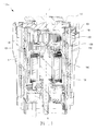
FIG. 1 , a section view of a mechanical linear actuator ("MLA") 100 is illustrated according to various embodiments. The MLA 100 may extend along the axis marked A-A', with A being located near a distal portion of MLA 100 and A' being near a proximal portion ofMLA 100. The MLA 100 may, as described above, be involved in the application of a braking force to an aircraft wheel. The MLA 100 assembly may comprise anMLA housing 101, which may extend along the axis A-A'. The MLAhousing 101 may house a variety of components, including, for example, aball nut piston 110, aball screw 120, and an actuator drive unit ("ADU") 130. The ADU 130 may be located within an ADUhousing 140. Generally, the ADU 130 may rotate and may drive the ball screw 120 through a plurality of rotations. - The
ball screw 120 may comprise a series ofcross-under ball tracks 122. Theball nut piston 110 may comprise ahelical track 112. A plurality of balls may be located within thecross-under ball tracks 122. The balls may be metal spheres which decrease friction and transfer loads between adjacent components. As the ball screw 120 rotates, theball nut piston 110 may translate distally and/or proximally along the axis A-A' (depending upon the direction of rotation of the ball screw 120). Theball nut piston 110 may be coupled to a disc or "puck," 150 at a distal end thereof. Thepuck 150 may exert a pressure against a brake stack coupled to an aircraft wheel to impede or halt rotation of the wheel. The pressure may be transferred back through thepuck 150, to theball nut piston 110, to theball screw 120, and to theADU housing 140. A series of parallel ball screwannular tracks 121 and a series of annular ADU housingannular tracks 141 may form a series ofannular raceways 160. Balls in the series of parallelannular raceways 160 between theball screw 120 and theADU housing 140 may distribute the load applied on theADU housing 140 from theball screw 120. - Referring to
FIG. 2 , a perspective view of aball screw 220 and anADU housing 240 is illustrated according to various embodiments. Theball screw 220 may comprise three cross-under ball tracks 222, 224, 226. The three cross-under ball tracks 222, 224, 226 are independent (i.e. balls incross-under ball track 222 do not enter cross-under ball tracks 224, 226). Eachcross-under ball track cross-under portion 227 is shown forcross-under ball track 226. At thecross-under portion 227, a depth of thecross-under ball track 226 may be greater than the remaining portion of thecross-under ball track 226, allowing balls to move under the threads of a ball nut piston. - The
ball screw 220 may comprise awindow 228. Thewindow 228 may allow balls to be inserted into theannular raceways 260. Once the balls have been inserted through thewindow 228, a plug may be inserted in thewindow 228 to prevent the balls from falling out through thewindow 228. Thewindow 228 may extend axially across all threeannular raceways 260 in order to allow balls to be inserted into eachannular raceway 260. However, thewindow 228 may remove material from theball screw 220, which may decrease the strength of theball screw 220. In particular, region R, located between thewindow 228 and theproximal edge 229 of theball screw 220 may be susceptible to high cycle fatigue due to concentrated loading in this area. - Referring to
FIG. 3 , a perspective view of aball screw 300 having multiple windows is illustrated according to various embodiments. Theball screw 300 may comprise a firstannular track 311, a secondannular track 312, and a thirdannular track 313. In various embodiments, theball screw 300 may comprise any number of annular tracks. Theball screw 300 may comprise a plurality of balls in theannular tracks ball screw 300 to an ADU housing. Theball screw 300 may comprise one or more ball screwalignment tabs 350 which align with a gear train and ADU housing which may be inserted within theball screw 300. - The
ball screw 300 may comprise a window for each annular track. Theball screw 300 may comprise afirst window 321 corresponding to the firstannular track 311, asecond window 322 corresponding to the secondannular track 312, and athird window 323 corresponding to the thirdannular track 313. Balls may be inserted through thefirst window 321 to fill the firstannular track 311, through thesecond window 322 to fill the secondannular track 312, and through thethird window 323 to fill the thirdannular track 313. Thefirst window 321, thesecond window 322, and thethird window 323 may individually be smaller than a window which spans across allannular tracks window plug 340 may be inserted into eachwindow windows - In various embodiments, the
windows ball screw 300. For example, thefirst window 321 may be separated from thesecond window 322 by 120° and thesecond window 322 may be separated from thethird window 323 by 120°, and thethird window 323 may be separated from thefirst window 321 by 120°. Similarly, in an embodiment with two windows, a first window may be separated from a second window by 180°. - In various embodiments, each
window ball screw 300 in which balls may cross under tracks in a ball nut piston. For example, theball screw 300 comprises a firstcross-under segment 331 where balls in a firstcross-under track 341 may cross under threads in a ball nut piston, a secondcross-under segment 332 where balls in a secondcross-under track 342 may cross under threads in a ball nut piston, and a thirdcross-under segment 333 where balls in a thirdcross-under track 343 may cross under balls in a ball nut piston. In the cross-under segments, one of the cross-under tracks may not be receiving a load from the ball nut piston. Thus, the stress around thewindows - Referring to
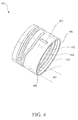
FIG. 4 , a perspective view of aball screw 400 having three annular tracks and two windows is illustrated according to various embodiments. Afirst window 421 may correspond to a firstannular track 411 closest to aproximal end 440 of theball screw 400. Asecond window 422 may correspond to a secondannular track 412 and a thirdannular track 413. The highest stress location may be located in region T located between thefirst window 421 and theproximal end 440 due to the small amount of material in region T. Thus, thefirst window 421 may be located in across-under segment 431. However, thefirst window 421 and thesecond window 422 may be equally separated around the circumference of theball screw 400. Thefirst window 421 and thesecond window 422 may be separated by 180°. Thus, in various embodiments thesecond window 422 is not located in a cross-under segment. - Referring to
FIG. 5 , aflow chart 500 of a method for assembling a ball screw assembly is illustrated according to various embodiments. A ball screw may be inserted into a ball nut piston (step 510). A plurality of balls may be inserted into cross-under tracks in the ball screw (step 520). A motor and gear train may be inserted into an ADU housing. A retainer may be disposed around the ADU housing. The ADU housing and gear train may then be inserted into the ball screw (step 530). The ADU housing and gear train may be aligned with ball screw alignment tabs in the ball screw. The alignment with the ball screw tabs may cause a series of annular tracks in the ball screw to be aligned with a series of annular tracks in the ADU housing to form a series of annular raceways. A first window in the ball screw may be aligned with a first annular track in the ADU housing, and a second window in the ball screw may be aligned with a second annular track in the ADU housing. A plurality of balls may be inserted through the first window into the first annular track (step 540). A plurality of balls may be inserted through the second window into the second annular track (step 550). In various embodiments, a plurality of balls may be inserted through the second window into a third annular track. However, in various embodiments, a plurality of balls may be inserted through a third window into the third annular track. A plug may be inserted into each window (step 560). The plugs may prevent the balls from falling out through the windows. The retainer may be slid around the plugs to retain the plugs in place. - Benefits, other advantages, and solutions to problems have been described herein with regard to specific embodiments. Furthermore, the connecting lines shown in the various figures contained herein are intended to represent exemplary functional relationships and/or physical couplings between the various elements. It should be noted that many alternative or additional functional relationships or physical connections may be present in a practical system. However, the benefits, advantages, solutions to problems, and any elements that may cause any benefit, advantage, or solution to occur or become more pronounced are not to be construed as critical, required, or essential features or elements of the disclosure. The scope of the disclosure is accordingly to be limited by nothing other than the appended claims, in which reference to an element in the singular is not intended to mean "one and only one" unless explicitly so stated, but rather "one or more." Moreover, where a phrase similar to "at least one of A, B, or C" is used in the claims, it is intended that the phrase be interpreted to mean that A alone may be present in an embodiment, B alone may be present in an embodiment, C alone may be present in an embodiment, or that any combination of the elements A, B and C may be present in a single embodiment; for example, A and B, A and C, B and C, or A and B and C.
- Systems, methods and apparatus are provided herein. In the detailed description herein, references to "various embodiments", "one embodiment", "an embodiment", "an example embodiment", etc., indicate that the embodiment described may include a particular feature, structure, or characteristic, but every embodiment may not necessarily include the particular feature, structure, or characteristic. Moreover, such phrases are not necessarily referring to the same embodiment. Further, when a particular feature, structure, or characteristic is described in connection with an embodiment, it is submitted that it is within the knowledge of one skilled in the art to affect such feature, structure, or characteristic in connection with other embodiments whether or not explicitly described. After reading the description, it will be apparent to one skilled in the relevant art(s) how to implement the disclosure in alternative embodiments.
- Furthermore, no element, component, or method step in the present disclosure is intended to be dedicated to the public regardless of whether the element, component, or method step is explicitly recited in the claims. No claim element herein is to be construed under the provisions of 35 U.S.C. 112(f), unless the element is expressly recited using the phrase "means for." As used herein, the terms "comprises", "comprising", or any other variation thereof, are intended to cover a non-exclusive inclusion, such that a process, method, article, or apparatus that comprises a list of elements does not include only those elements but may include other elements not expressly listed or inherent to such process, method, article, or apparatus.
Claims (15)
- A mechanical linear actuator ("MLA") (100) comprising:an actuator drive unit ("ADU") housing (140; 240) comprising a first ADU annular track (141) and a second ADU annular track (141); anda ball screw (120; 220; 300; 400) comprising:a first ball screw annular track (121; 311; 411), wherein the first ADU annular track (141) and the first ball screw annular track (121; 311; 411) form a first annular raceway (160; 260);a second ball screw annular track (312; 412), wherein the second ADU annular track (141) and the second ball screw annular track (312; 412) form a second annular raceway (160; 260);a first window (228; 321; 421) corresponding to the first annular raceway (160; 260); anda second window (322; 422) corresponding to the second annular raceway (160; 260).
- The MLA of claim 1, wherein the ball screw (120; 220; 300; 400) and the ADU housing (140; 240) form a third annular raceway (160; 260).
- The MLA of claim 2, wherein the ball screw (120; 220; 300; 400) comprises a third window (323) corresponding to the third annular raceway (160; 260).
- The MLA of claim 3, wherein the first window (321), the second window (322), and the third window (323) are equally spaced around a circumference of the ball screw (120; 220; 300; 400).
- The MLA of claim 1 or 2, wherein the second window (422) corresponds to the second annular raceway (160; 260) and a/the third annular raceway (160; 260).
- The MLA of claim 1, 2 or 5, wherein the first window (421) and the second window (422) are separated by 180° about the ball screw (120; 220; 300; 400).
- The MLA of any preceding claim, wherein the ball screw (120; 220; 300; 400) comprises a series of cross-under tracks (222, 224, 226; 341, 342, 343).
- The MLA of any preceding claim, further comprising a ball nut piston (110) disposed circumferentially about the ball screw (120; 220; 300; 400), wherein the ball nut piston (110) comprises a helical track (112).
- The MLA of any preceding claim, further comprising a plurality of balls disposed in the first annular raceway (160; 260) and the second annular raceway (160; 260), wherein the plurality of balls are configured to transfer load from the ball screw (120; 220; 300; 400) to the ADU housing (140; 240).
- A method of assembling a mechanical linear actuator ("MLA") (100) comprising:inserting an ADU housing (140; 240) within a ball screw (120; 220; 300; 400), such that a series of ball screw annular tracks (121; 311-313; 411-413) and a series of ADU housing annular tracks (141) form a first annular raceway (160; 260) and a second annular raceway (160; 260);aligning a first window (228; 321; 421) in the ball screw (120; 220; 300; 400) with the first annular raceway (160; 260) and a second window (322; 422) in the ball screw (120; 220; 300; 400) with the second annular raceway (160; 260);inserting a first plurality of balls through the first window (228; 321; 421); andinserting a second plurality of balls through the second window (322; 422).
- The method of claim 10, further comprising inserting a first plug (340) into the first window (228; 321; 421) and a second plug (340) into the second window (322; 422).
- The method of claim 10 or 11, further comprising aligning the ADU housing (140; 240) with a ball screw alignment tab (350).
- The method of claim 10, 11 or 12, further comprising inserting the ball screw (120; 220; 300; 400) within a ball nut piston (110).
- The method of any of claims 10 to 13, further comprising inserting a third plurality of balls through a third window (323; 423) in the ball screw (120; 220; 300; 400).
- The method of any of claims 10 to 13, further comprising inserting a third plurality of balls into cross-under tracks (222, 224, 226; 341, 342, 343) in the ball screw (120; 220; 300; 400).
Applications Claiming Priority (1)
| Application Number | Priority Date | Filing Date | Title |
|---|---|---|---|
| US14/528,816 US9791025B2 (en) | 2014-10-30 | 2014-10-30 | Ball screw assembly for aircraft brake |
Publications (2)
| Publication Number | Publication Date |
|---|---|
| EP3025920A1 true EP3025920A1 (en) | 2016-06-01 |
| EP3025920B1 EP3025920B1 (en) | 2018-08-08 |
Family
ID=54477843
Family Applications (1)
| Application Number | Title | Priority Date | Filing Date |
|---|---|---|---|
| EP15192081.6A Active EP3025920B1 (en) | 2014-10-30 | 2015-10-29 | Ball screw assembly for aircraft brake |
Country Status (2)
| Country | Link |
|---|---|
| US (2) | US9791025B2 (en) |
| EP (1) | EP3025920B1 (en) |
Families Citing this family (5)
| Publication number | Priority date | Publication date | Assignee | Title |
|---|---|---|---|---|
| US9791025B2 (en) | 2014-10-30 | 2017-10-17 | Goodrich Corporatioln | Ball screw assembly for aircraft brake |
| US10830321B2 (en) * | 2016-02-19 | 2020-11-10 | Goodrich Corporation | Actuator ball screw for improved load sharing |
| US10106139B2 (en) | 2017-02-02 | 2018-10-23 | Goodrich Corporation | Brake systems and methods |
| US11105404B2 (en) * | 2017-05-30 | 2021-08-31 | UMBRAGROUP S.p.A. | Fault-tolerant electromechanical linear actuators |
| DE102018111128A1 (en) * | 2018-05-09 | 2019-11-14 | Ipgate Ag | Electromotive driven helical gear for driving an adjustment |
Citations (3)
| Publication number | Priority date | Publication date | Assignee | Title |
|---|---|---|---|---|
| WO2001038750A1 (en) * | 1999-11-23 | 2001-05-31 | Skf Engineering And Research Centre B.V. | Actuator with misalignment compensation |
| US20050077782A1 (en) * | 2003-10-08 | 2005-04-14 | Honda Motor Co., Ltd. | Electrically driven parking brake device |
| JP2009127737A (en) * | 2007-11-22 | 2009-06-11 | Hitachi Ltd | Electric disc brake |
Family Cites Families (7)
| Publication number | Priority date | Publication date | Assignee | Title |
|---|---|---|---|---|
| US3951470A (en) * | 1973-08-23 | 1976-04-20 | Bralorne Resources Limited | Drill steel idler guide |
| US4542809A (en) * | 1979-07-30 | 1985-09-24 | Goodyear Aerospace Corporation | Electrically actuated aircraft brakes |
| US6325182B1 (en) * | 1998-03-27 | 2001-12-04 | Tokico, Ltd. | Motor-driven brake system |
| US6389915B1 (en) * | 1999-05-17 | 2002-05-21 | Alliedsignal, Inc. | Dual load path ball screw with rod end swivel |
| US8015889B2 (en) * | 2005-11-15 | 2011-09-13 | Honeywell International Inc. | Ballscrew with an integral high-efficiency thrust bearing |
| US8402852B2 (en) * | 2011-01-18 | 2013-03-26 | Goodrich Corporation | Ballscrew assembly |
| US9791025B2 (en) | 2014-10-30 | 2017-10-17 | Goodrich Corporatioln | Ball screw assembly for aircraft brake |
-
2014
- 2014-10-30 US US14/528,816 patent/US9791025B2/en active Active
-
2015
- 2015-10-29 EP EP15192081.6A patent/EP3025920B1/en active Active
-
2017
- 2017-09-19 US US15/709,149 patent/US10578198B2/en active Active
Patent Citations (3)
| Publication number | Priority date | Publication date | Assignee | Title |
|---|---|---|---|---|
| WO2001038750A1 (en) * | 1999-11-23 | 2001-05-31 | Skf Engineering And Research Centre B.V. | Actuator with misalignment compensation |
| US20050077782A1 (en) * | 2003-10-08 | 2005-04-14 | Honda Motor Co., Ltd. | Electrically driven parking brake device |
| JP2009127737A (en) * | 2007-11-22 | 2009-06-11 | Hitachi Ltd | Electric disc brake |
Also Published As
| Publication number | Publication date |
|---|---|
| US20160123445A1 (en) | 2016-05-05 |
| EP3025920B1 (en) | 2018-08-08 |
| US20180031094A1 (en) | 2018-02-01 |
| US9791025B2 (en) | 2017-10-17 |
| US10578198B2 (en) | 2020-03-03 |
Similar Documents
| Publication | Publication Date | Title |
|---|---|---|
| US10578198B2 (en) | Ball screw assembly for aircraft brake | |
| US8986127B2 (en) | Flexible coupling means and a mechanical transmission | |
| US9482325B2 (en) | Systems and methods for load cell and multi-row thrust bearing integration with ball screw and actuator drive unit housing | |
| AU2009254254A1 (en) | Assembly aid for radial cylinder rolling bearing | |
| EP3121476B1 (en) | Aircraft brake actuator assemblies | |
| EP2947342A1 (en) | Torque limiter | |
| US12203532B2 (en) | Torsionally compliant actuator end stop | |
| EP3486519B1 (en) | Actuator ball screw for improved load sharing | |
| EP3020999B1 (en) | Aircraft brake puck assembly | |
| DE102010035784A1 (en) | Multi-ring rolling bearing for motor vehicle, has thermal compensating element which is arranged between intermediate rings for supporting rolling elements of rolling rings | |
| WO2008007474A1 (en) | Bearing device for wheel | |
| US9482326B2 (en) | Electromechanical actuator | |
| DE102015014833B3 (en) | Safety bearing system | |
| US20170203837A1 (en) | Drive shaft system hanger bearing | |
| EP2965961A2 (en) | Voice coil linear activated park brake | |
| EP3540259B1 (en) | Torque button lock clip | |
| EP3715244B1 (en) | Bolted joint for wheel assemblies | |
| EP3587140B1 (en) | Torque bar retention for wheel assemblies | |
| EP3441637A1 (en) | Differential torque plate barrel thickness | |
| DE102014210416A1 (en) | drive wheel | |
| WO2013013795A1 (en) | Disengagement system for a double clutch | |
| EP2785983B1 (en) | A structural joint for connecting a first component to a segmented second component |
Legal Events
| Date | Code | Title | Description |
|---|---|---|---|
| PUAI | Public reference made under article 153(3) epc to a published international application that has entered the european phase |
Free format text: ORIGINAL CODE: 0009012 |
|
| AK | Designated contracting states |
Kind code of ref document: A1 Designated state(s): AL AT BE BG CH CY CZ DE DK EE ES FI FR GB GR HR HU IE IS IT LI LT LU LV MC MK MT NL NO PL PT RO RS SE SI SK SM TR |
|
| AX | Request for extension of the european patent |
Extension state: BA ME |
|
| STAA | Information on the status of an ep patent application or granted ep patent |
Free format text: STATUS: REQUEST FOR EXAMINATION WAS MADE |
|
| 17P | Request for examination filed |
Effective date: 20161130 |
|
| RBV | Designated contracting states (corrected) |
Designated state(s): AL AT BE BG CH CY CZ DE DK EE ES FI FR GB GR HR HU IE IS IT LI LT LU LV MC MK MT NL NO PL PT RO RS SE SI SK SM TR |
|
| GRAP | Despatch of communication of intention to grant a patent |
Free format text: ORIGINAL CODE: EPIDOSNIGR1 |
|
| STAA | Information on the status of an ep patent application or granted ep patent |
Free format text: STATUS: GRANT OF PATENT IS INTENDED |
|
| INTG | Intention to grant announced |
Effective date: 20180216 |
|
| GRAS | Grant fee paid |
Free format text: ORIGINAL CODE: EPIDOSNIGR3 |
|
| GRAA | (expected) grant |
Free format text: ORIGINAL CODE: 0009210 |
|
| STAA | Information on the status of an ep patent application or granted ep patent |
Free format text: STATUS: THE PATENT HAS BEEN GRANTED |
|
| AK | Designated contracting states |
Kind code of ref document: B1 Designated state(s): AL AT BE BG CH CY CZ DE DK EE ES FI FR GB GR HR HU IE IS IT LI LT LU LV MC MK MT NL NO PL PT RO RS SE SI SK SM TR |
|
| REG | Reference to a national code |
Ref country code: GB Ref legal event code: FG4D |
|
| REG | Reference to a national code |
Ref country code: CH Ref legal event code: EP Ref country code: AT Ref legal event code: REF Ref document number: 1026635 Country of ref document: AT Kind code of ref document: T Effective date: 20180815 |
|
| REG | Reference to a national code |
Ref country code: IE Ref legal event code: FG4D |
|
| REG | Reference to a national code |
Ref country code: DE Ref legal event code: R096 Ref document number: 602015014567 Country of ref document: DE |
|
| REG | Reference to a national code |
Ref country code: FR Ref legal event code: PLFP Year of fee payment: 4 |
|
| REG | Reference to a national code |
Ref country code: NL Ref legal event code: MP Effective date: 20180808 |
|
| REG | Reference to a national code |
Ref country code: LT Ref legal event code: MG4D |
|
| REG | Reference to a national code |
Ref country code: AT Ref legal event code: MK05 Ref document number: 1026635 Country of ref document: AT Kind code of ref document: T Effective date: 20180808 |
|
| PG25 | Lapsed in a contracting state [announced via postgrant information from national office to epo] |
Ref country code: BG Free format text: LAPSE BECAUSE OF FAILURE TO SUBMIT A TRANSLATION OF THE DESCRIPTION OR TO PAY THE FEE WITHIN THE PRESCRIBED TIME-LIMIT Effective date: 20181108 Ref country code: NL Free format text: LAPSE BECAUSE OF FAILURE TO SUBMIT A TRANSLATION OF THE DESCRIPTION OR TO PAY THE FEE WITHIN THE PRESCRIBED TIME-LIMIT Effective date: 20180808 Ref country code: RS Free format text: LAPSE BECAUSE OF FAILURE TO SUBMIT A TRANSLATION OF THE DESCRIPTION OR TO PAY THE FEE WITHIN THE PRESCRIBED TIME-LIMIT Effective date: 20180808 Ref country code: IS Free format text: LAPSE BECAUSE OF FAILURE TO SUBMIT A TRANSLATION OF THE DESCRIPTION OR TO PAY THE FEE WITHIN THE PRESCRIBED TIME-LIMIT Effective date: 20181208 Ref country code: LT Free format text: LAPSE BECAUSE OF FAILURE TO SUBMIT A TRANSLATION OF THE DESCRIPTION OR TO PAY THE FEE WITHIN THE PRESCRIBED TIME-LIMIT Effective date: 20180808 Ref country code: AT Free format text: LAPSE BECAUSE OF FAILURE TO SUBMIT A TRANSLATION OF THE DESCRIPTION OR TO PAY THE FEE WITHIN THE PRESCRIBED TIME-LIMIT Effective date: 20180808 Ref country code: NO Free format text: LAPSE BECAUSE OF FAILURE TO SUBMIT A TRANSLATION OF THE DESCRIPTION OR TO PAY THE FEE WITHIN THE PRESCRIBED TIME-LIMIT Effective date: 20181108 Ref country code: PL Free format text: LAPSE BECAUSE OF FAILURE TO SUBMIT A TRANSLATION OF THE DESCRIPTION OR TO PAY THE FEE WITHIN THE PRESCRIBED TIME-LIMIT Effective date: 20180808 Ref country code: FI Free format text: LAPSE BECAUSE OF FAILURE TO SUBMIT A TRANSLATION OF THE DESCRIPTION OR TO PAY THE FEE WITHIN THE PRESCRIBED TIME-LIMIT Effective date: 20180808 Ref country code: GR Free format text: LAPSE BECAUSE OF FAILURE TO SUBMIT A TRANSLATION OF THE DESCRIPTION OR TO PAY THE FEE WITHIN THE PRESCRIBED TIME-LIMIT Effective date: 20181109 Ref country code: SE Free format text: LAPSE BECAUSE OF FAILURE TO SUBMIT A TRANSLATION OF THE DESCRIPTION OR TO PAY THE FEE WITHIN THE PRESCRIBED TIME-LIMIT Effective date: 20180808 |
|
| PG25 | Lapsed in a contracting state [announced via postgrant information from national office to epo] |
Ref country code: LV Free format text: LAPSE BECAUSE OF FAILURE TO SUBMIT A TRANSLATION OF THE DESCRIPTION OR TO PAY THE FEE WITHIN THE PRESCRIBED TIME-LIMIT Effective date: 20180808 Ref country code: AL Free format text: LAPSE BECAUSE OF FAILURE TO SUBMIT A TRANSLATION OF THE DESCRIPTION OR TO PAY THE FEE WITHIN THE PRESCRIBED TIME-LIMIT Effective date: 20180808 Ref country code: HR Free format text: LAPSE BECAUSE OF FAILURE TO SUBMIT A TRANSLATION OF THE DESCRIPTION OR TO PAY THE FEE WITHIN THE PRESCRIBED TIME-LIMIT Effective date: 20180808 |
|
| PG25 | Lapsed in a contracting state [announced via postgrant information from national office to epo] |
Ref country code: EE Free format text: LAPSE BECAUSE OF FAILURE TO SUBMIT A TRANSLATION OF THE DESCRIPTION OR TO PAY THE FEE WITHIN THE PRESCRIBED TIME-LIMIT Effective date: 20180808 Ref country code: RO Free format text: LAPSE BECAUSE OF FAILURE TO SUBMIT A TRANSLATION OF THE DESCRIPTION OR TO PAY THE FEE WITHIN THE PRESCRIBED TIME-LIMIT Effective date: 20180808 Ref country code: IT Free format text: LAPSE BECAUSE OF FAILURE TO SUBMIT A TRANSLATION OF THE DESCRIPTION OR TO PAY THE FEE WITHIN THE PRESCRIBED TIME-LIMIT Effective date: 20180808 Ref country code: ES Free format text: LAPSE BECAUSE OF FAILURE TO SUBMIT A TRANSLATION OF THE DESCRIPTION OR TO PAY THE FEE WITHIN THE PRESCRIBED TIME-LIMIT Effective date: 20180808 Ref country code: CZ Free format text: LAPSE BECAUSE OF FAILURE TO SUBMIT A TRANSLATION OF THE DESCRIPTION OR TO PAY THE FEE WITHIN THE PRESCRIBED TIME-LIMIT Effective date: 20180808 |
|
| REG | Reference to a national code |
Ref country code: DE Ref legal event code: R119 Ref document number: 602015014567 Country of ref document: DE |
|
| PG25 | Lapsed in a contracting state [announced via postgrant information from national office to epo] |
Ref country code: SM Free format text: LAPSE BECAUSE OF FAILURE TO SUBMIT A TRANSLATION OF THE DESCRIPTION OR TO PAY THE FEE WITHIN THE PRESCRIBED TIME-LIMIT Effective date: 20180808 Ref country code: SK Free format text: LAPSE BECAUSE OF FAILURE TO SUBMIT A TRANSLATION OF THE DESCRIPTION OR TO PAY THE FEE WITHIN THE PRESCRIBED TIME-LIMIT Effective date: 20180808 Ref country code: DK Free format text: LAPSE BECAUSE OF FAILURE TO SUBMIT A TRANSLATION OF THE DESCRIPTION OR TO PAY THE FEE WITHIN THE PRESCRIBED TIME-LIMIT Effective date: 20180808 |
|
| REG | Reference to a national code |
Ref country code: CH Ref legal event code: PL |
|
| PLBE | No opposition filed within time limit |
Free format text: ORIGINAL CODE: 0009261 |
|
| STAA | Information on the status of an ep patent application or granted ep patent |
Free format text: STATUS: NO OPPOSITION FILED WITHIN TIME LIMIT |
|
| REG | Reference to a national code |
Ref country code: BE Ref legal event code: MM Effective date: 20181031 |
|
| PG25 | Lapsed in a contracting state [announced via postgrant information from national office to epo] |
Ref country code: LU Free format text: LAPSE BECAUSE OF NON-PAYMENT OF DUE FEES Effective date: 20181029 Ref country code: MC Free format text: LAPSE BECAUSE OF FAILURE TO SUBMIT A TRANSLATION OF THE DESCRIPTION OR TO PAY THE FEE WITHIN THE PRESCRIBED TIME-LIMIT Effective date: 20180808 |
|
| 26N | No opposition filed |
Effective date: 20190509 |
|
| REG | Reference to a national code |
Ref country code: IE Ref legal event code: MM4A |
|
| PG25 | Lapsed in a contracting state [announced via postgrant information from national office to epo] |
Ref country code: DE Free format text: LAPSE BECAUSE OF NON-PAYMENT OF DUE FEES Effective date: 20190501 |
|
| PG25 | Lapsed in a contracting state [announced via postgrant information from national office to epo] |
Ref country code: SI Free format text: LAPSE BECAUSE OF FAILURE TO SUBMIT A TRANSLATION OF THE DESCRIPTION OR TO PAY THE FEE WITHIN THE PRESCRIBED TIME-LIMIT Effective date: 20180808 Ref country code: LI Free format text: LAPSE BECAUSE OF NON-PAYMENT OF DUE FEES Effective date: 20181031 Ref country code: CH Free format text: LAPSE BECAUSE OF NON-PAYMENT OF DUE FEES Effective date: 20181031 Ref country code: BE Free format text: LAPSE BECAUSE OF NON-PAYMENT OF DUE FEES Effective date: 20181031 |
|
| PG25 | Lapsed in a contracting state [announced via postgrant information from national office to epo] |
Ref country code: IE Free format text: LAPSE BECAUSE OF NON-PAYMENT OF DUE FEES Effective date: 20181029 |
|
| PG25 | Lapsed in a contracting state [announced via postgrant information from national office to epo] |
Ref country code: MT Free format text: LAPSE BECAUSE OF NON-PAYMENT OF DUE FEES Effective date: 20181029 |
|
| PG25 | Lapsed in a contracting state [announced via postgrant information from national office to epo] |
Ref country code: TR Free format text: LAPSE BECAUSE OF FAILURE TO SUBMIT A TRANSLATION OF THE DESCRIPTION OR TO PAY THE FEE WITHIN THE PRESCRIBED TIME-LIMIT Effective date: 20180808 |
|
| PG25 | Lapsed in a contracting state [announced via postgrant information from national office to epo] |
Ref country code: PT Free format text: LAPSE BECAUSE OF FAILURE TO SUBMIT A TRANSLATION OF THE DESCRIPTION OR TO PAY THE FEE WITHIN THE PRESCRIBED TIME-LIMIT Effective date: 20180808 |
|
| PG25 | Lapsed in a contracting state [announced via postgrant information from national office to epo] |
Ref country code: CY Free format text: LAPSE BECAUSE OF FAILURE TO SUBMIT A TRANSLATION OF THE DESCRIPTION OR TO PAY THE FEE WITHIN THE PRESCRIBED TIME-LIMIT Effective date: 20180808 Ref country code: HU Free format text: LAPSE BECAUSE OF FAILURE TO SUBMIT A TRANSLATION OF THE DESCRIPTION OR TO PAY THE FEE WITHIN THE PRESCRIBED TIME-LIMIT; INVALID AB INITIO Effective date: 20151029 Ref country code: MK Free format text: LAPSE BECAUSE OF NON-PAYMENT OF DUE FEES Effective date: 20180808 |
|
| P01 | Opt-out of the competence of the unified patent court (upc) registered |
Effective date: 20230522 |
|
| PGFP | Annual fee paid to national office [announced via postgrant information from national office to epo] |
Ref country code: GB Payment date: 20250923 Year of fee payment: 11 |
|
| PGFP | Annual fee paid to national office [announced via postgrant information from national office to epo] |
Ref country code: FR Payment date: 20250924 Year of fee payment: 11 |