EP3025902A1 - Evse handle with automatic thermal shut down by ntc to ground - Google Patents
Evse handle with automatic thermal shut down by ntc to ground Download PDFInfo
- Publication number
- EP3025902A1 EP3025902A1 EP15193312.4A EP15193312A EP3025902A1 EP 3025902 A1 EP3025902 A1 EP 3025902A1 EP 15193312 A EP15193312 A EP 15193312A EP 3025902 A1 EP3025902 A1 EP 3025902A1
- Authority
- EP
- European Patent Office
- Prior art keywords
- conductor
- thermistor
- charging
- temperature
- resistor
- Prior art date
- Legal status (The legal status is an assumption and is not a legal conclusion. Google has not performed a legal analysis and makes no representation as to the accuracy of the status listed.)
- Granted
Links
Images



Classifications
-
- B—PERFORMING OPERATIONS; TRANSPORTING
- B60—VEHICLES IN GENERAL
- B60L—PROPULSION OF ELECTRICALLY-PROPELLED VEHICLES; SUPPLYING ELECTRIC POWER FOR AUXILIARY EQUIPMENT OF ELECTRICALLY-PROPELLED VEHICLES; ELECTRODYNAMIC BRAKE SYSTEMS FOR VEHICLES IN GENERAL; MAGNETIC SUSPENSION OR LEVITATION FOR VEHICLES; MONITORING OPERATING VARIABLES OF ELECTRICALLY-PROPELLED VEHICLES; ELECTRIC SAFETY DEVICES FOR ELECTRICALLY-PROPELLED VEHICLES
- B60L3/00—Electric devices on electrically-propelled vehicles for safety purposes; Monitoring operating variables, e.g. speed, deceleration or energy consumption
-
- H—ELECTRICITY
- H02—GENERATION; CONVERSION OR DISTRIBUTION OF ELECTRIC POWER
- H02H—EMERGENCY PROTECTIVE CIRCUIT ARRANGEMENTS
- H02H5/00—Emergency protective circuit arrangements for automatic disconnection directly responsive to an undesired change from normal non-electric working conditions with or without subsequent reconnection
- H02H5/04—Emergency protective circuit arrangements for automatic disconnection directly responsive to an undesired change from normal non-electric working conditions with or without subsequent reconnection responsive to abnormal temperature
- H02H5/042—Emergency protective circuit arrangements for automatic disconnection directly responsive to an undesired change from normal non-electric working conditions with or without subsequent reconnection responsive to abnormal temperature using temperature dependent resistors
-
- B—PERFORMING OPERATIONS; TRANSPORTING
- B60—VEHICLES IN GENERAL
- B60L—PROPULSION OF ELECTRICALLY-PROPELLED VEHICLES; SUPPLYING ELECTRIC POWER FOR AUXILIARY EQUIPMENT OF ELECTRICALLY-PROPELLED VEHICLES; ELECTRODYNAMIC BRAKE SYSTEMS FOR VEHICLES IN GENERAL; MAGNETIC SUSPENSION OR LEVITATION FOR VEHICLES; MONITORING OPERATING VARIABLES OF ELECTRICALLY-PROPELLED VEHICLES; ELECTRIC SAFETY DEVICES FOR ELECTRICALLY-PROPELLED VEHICLES
- B60L3/00—Electric devices on electrically-propelled vehicles for safety purposes; Monitoring operating variables, e.g. speed, deceleration or energy consumption
- B60L3/04—Cutting off the power supply under fault conditions
-
- B—PERFORMING OPERATIONS; TRANSPORTING
- B60—VEHICLES IN GENERAL
- B60L—PROPULSION OF ELECTRICALLY-PROPELLED VEHICLES; SUPPLYING ELECTRIC POWER FOR AUXILIARY EQUIPMENT OF ELECTRICALLY-PROPELLED VEHICLES; ELECTRODYNAMIC BRAKE SYSTEMS FOR VEHICLES IN GENERAL; MAGNETIC SUSPENSION OR LEVITATION FOR VEHICLES; MONITORING OPERATING VARIABLES OF ELECTRICALLY-PROPELLED VEHICLES; ELECTRIC SAFETY DEVICES FOR ELECTRICALLY-PROPELLED VEHICLES
- B60L53/00—Methods of charging batteries, specially adapted for electric vehicles; Charging stations or on-board charging equipment therefor; Exchange of energy storage elements in electric vehicles
-
- B—PERFORMING OPERATIONS; TRANSPORTING
- B60—VEHICLES IN GENERAL
- B60L—PROPULSION OF ELECTRICALLY-PROPELLED VEHICLES; SUPPLYING ELECTRIC POWER FOR AUXILIARY EQUIPMENT OF ELECTRICALLY-PROPELLED VEHICLES; ELECTRODYNAMIC BRAKE SYSTEMS FOR VEHICLES IN GENERAL; MAGNETIC SUSPENSION OR LEVITATION FOR VEHICLES; MONITORING OPERATING VARIABLES OF ELECTRICALLY-PROPELLED VEHICLES; ELECTRIC SAFETY DEVICES FOR ELECTRICALLY-PROPELLED VEHICLES
- B60L53/00—Methods of charging batteries, specially adapted for electric vehicles; Charging stations or on-board charging equipment therefor; Exchange of energy storage elements in electric vehicles
- B60L53/10—Methods of charging batteries, specially adapted for electric vehicles; Charging stations or on-board charging equipment therefor; Exchange of energy storage elements in electric vehicles characterised by the energy transfer between the charging station and the vehicle
- B60L53/14—Conductive energy transfer
-
- B—PERFORMING OPERATIONS; TRANSPORTING
- B60—VEHICLES IN GENERAL
- B60L—PROPULSION OF ELECTRICALLY-PROPELLED VEHICLES; SUPPLYING ELECTRIC POWER FOR AUXILIARY EQUIPMENT OF ELECTRICALLY-PROPELLED VEHICLES; ELECTRODYNAMIC BRAKE SYSTEMS FOR VEHICLES IN GENERAL; MAGNETIC SUSPENSION OR LEVITATION FOR VEHICLES; MONITORING OPERATING VARIABLES OF ELECTRICALLY-PROPELLED VEHICLES; ELECTRIC SAFETY DEVICES FOR ELECTRICALLY-PROPELLED VEHICLES
- B60L53/00—Methods of charging batteries, specially adapted for electric vehicles; Charging stations or on-board charging equipment therefor; Exchange of energy storage elements in electric vehicles
- B60L53/10—Methods of charging batteries, specially adapted for electric vehicles; Charging stations or on-board charging equipment therefor; Exchange of energy storage elements in electric vehicles characterised by the energy transfer between the charging station and the vehicle
- B60L53/14—Conductive energy transfer
- B60L53/16—Connectors, e.g. plugs or sockets, specially adapted for charging electric vehicles
-
- B—PERFORMING OPERATIONS; TRANSPORTING
- B60—VEHICLES IN GENERAL
- B60L—PROPULSION OF ELECTRICALLY-PROPELLED VEHICLES; SUPPLYING ELECTRIC POWER FOR AUXILIARY EQUIPMENT OF ELECTRICALLY-PROPELLED VEHICLES; ELECTRODYNAMIC BRAKE SYSTEMS FOR VEHICLES IN GENERAL; MAGNETIC SUSPENSION OR LEVITATION FOR VEHICLES; MONITORING OPERATING VARIABLES OF ELECTRICALLY-PROPELLED VEHICLES; ELECTRIC SAFETY DEVICES FOR ELECTRICALLY-PROPELLED VEHICLES
- B60L53/00—Methods of charging batteries, specially adapted for electric vehicles; Charging stations or on-board charging equipment therefor; Exchange of energy storage elements in electric vehicles
- B60L53/10—Methods of charging batteries, specially adapted for electric vehicles; Charging stations or on-board charging equipment therefor; Exchange of energy storage elements in electric vehicles characterised by the energy transfer between the charging station and the vehicle
- B60L53/14—Conductive energy transfer
- B60L53/18—Cables specially adapted for charging electric vehicles
-
- B—PERFORMING OPERATIONS; TRANSPORTING
- B60—VEHICLES IN GENERAL
- B60L—PROPULSION OF ELECTRICALLY-PROPELLED VEHICLES; SUPPLYING ELECTRIC POWER FOR AUXILIARY EQUIPMENT OF ELECTRICALLY-PROPELLED VEHICLES; ELECTRODYNAMIC BRAKE SYSTEMS FOR VEHICLES IN GENERAL; MAGNETIC SUSPENSION OR LEVITATION FOR VEHICLES; MONITORING OPERATING VARIABLES OF ELECTRICALLY-PROPELLED VEHICLES; ELECTRIC SAFETY DEVICES FOR ELECTRICALLY-PROPELLED VEHICLES
- B60L53/00—Methods of charging batteries, specially adapted for electric vehicles; Charging stations or on-board charging equipment therefor; Exchange of energy storage elements in electric vehicles
- B60L53/30—Constructional details of charging stations
-
- H—ELECTRICITY
- H02—GENERATION; CONVERSION OR DISTRIBUTION OF ELECTRIC POWER
- H02H—EMERGENCY PROTECTIVE CIRCUIT ARRANGEMENTS
- H02H3/00—Emergency protective circuit arrangements for automatic disconnection directly responsive to an undesired change from normal electric working condition with or without subsequent reconnection ; integrated protection
- H02H3/02—Details
- H02H3/021—Details concerning the disconnection itself, e.g. at a particular instant, particularly at zero value of current, disconnection in a predetermined order
- H02H3/023—Details concerning the disconnection itself, e.g. at a particular instant, particularly at zero value of current, disconnection in a predetermined order by short-circuiting
-
- H—ELECTRICITY
- H02—GENERATION; CONVERSION OR DISTRIBUTION OF ELECTRIC POWER
- H02H—EMERGENCY PROTECTIVE CIRCUIT ARRANGEMENTS
- H02H5/00—Emergency protective circuit arrangements for automatic disconnection directly responsive to an undesired change from normal non-electric working conditions with or without subsequent reconnection
- H02H5/04—Emergency protective circuit arrangements for automatic disconnection directly responsive to an undesired change from normal non-electric working conditions with or without subsequent reconnection responsive to abnormal temperature
-
- B—PERFORMING OPERATIONS; TRANSPORTING
- B60—VEHICLES IN GENERAL
- B60L—PROPULSION OF ELECTRICALLY-PROPELLED VEHICLES; SUPPLYING ELECTRIC POWER FOR AUXILIARY EQUIPMENT OF ELECTRICALLY-PROPELLED VEHICLES; ELECTRODYNAMIC BRAKE SYSTEMS FOR VEHICLES IN GENERAL; MAGNETIC SUSPENSION OR LEVITATION FOR VEHICLES; MONITORING OPERATING VARIABLES OF ELECTRICALLY-PROPELLED VEHICLES; ELECTRIC SAFETY DEVICES FOR ELECTRICALLY-PROPELLED VEHICLES
- B60L2240/00—Control parameters of input or output; Target parameters
- B60L2240/10—Vehicle control parameters
- B60L2240/36—Temperature of vehicle components or parts
-
- Y—GENERAL TAGGING OF NEW TECHNOLOGICAL DEVELOPMENTS; GENERAL TAGGING OF CROSS-SECTIONAL TECHNOLOGIES SPANNING OVER SEVERAL SECTIONS OF THE IPC; TECHNICAL SUBJECTS COVERED BY FORMER USPC CROSS-REFERENCE ART COLLECTIONS [XRACs] AND DIGESTS
- Y02—TECHNOLOGIES OR APPLICATIONS FOR MITIGATION OR ADAPTATION AGAINST CLIMATE CHANGE
- Y02T—CLIMATE CHANGE MITIGATION TECHNOLOGIES RELATED TO TRANSPORTATION
- Y02T10/00—Road transport of goods or passengers
- Y02T10/60—Other road transportation technologies with climate change mitigation effect
- Y02T10/70—Energy storage systems for electromobility, e.g. batteries
-
- Y—GENERAL TAGGING OF NEW TECHNOLOGICAL DEVELOPMENTS; GENERAL TAGGING OF CROSS-SECTIONAL TECHNOLOGIES SPANNING OVER SEVERAL SECTIONS OF THE IPC; TECHNICAL SUBJECTS COVERED BY FORMER USPC CROSS-REFERENCE ART COLLECTIONS [XRACs] AND DIGESTS
- Y02—TECHNOLOGIES OR APPLICATIONS FOR MITIGATION OR ADAPTATION AGAINST CLIMATE CHANGE
- Y02T—CLIMATE CHANGE MITIGATION TECHNOLOGIES RELATED TO TRANSPORTATION
- Y02T10/00—Road transport of goods or passengers
- Y02T10/60—Other road transportation technologies with climate change mitigation effect
- Y02T10/7072—Electromobility specific charging systems or methods for batteries, ultracapacitors, supercapacitors or double-layer capacitors
-
- Y—GENERAL TAGGING OF NEW TECHNOLOGICAL DEVELOPMENTS; GENERAL TAGGING OF CROSS-SECTIONAL TECHNOLOGIES SPANNING OVER SEVERAL SECTIONS OF THE IPC; TECHNICAL SUBJECTS COVERED BY FORMER USPC CROSS-REFERENCE ART COLLECTIONS [XRACs] AND DIGESTS
- Y02—TECHNOLOGIES OR APPLICATIONS FOR MITIGATION OR ADAPTATION AGAINST CLIMATE CHANGE
- Y02T—CLIMATE CHANGE MITIGATION TECHNOLOGIES RELATED TO TRANSPORTATION
- Y02T90/00—Enabling technologies or technologies with a potential or indirect contribution to GHG emissions mitigation
- Y02T90/10—Technologies relating to charging of electric vehicles
- Y02T90/12—Electric charging stations
-
- Y—GENERAL TAGGING OF NEW TECHNOLOGICAL DEVELOPMENTS; GENERAL TAGGING OF CROSS-SECTIONAL TECHNOLOGIES SPANNING OVER SEVERAL SECTIONS OF THE IPC; TECHNICAL SUBJECTS COVERED BY FORMER USPC CROSS-REFERENCE ART COLLECTIONS [XRACs] AND DIGESTS
- Y02—TECHNOLOGIES OR APPLICATIONS FOR MITIGATION OR ADAPTATION AGAINST CLIMATE CHANGE
- Y02T—CLIMATE CHANGE MITIGATION TECHNOLOGIES RELATED TO TRANSPORTATION
- Y02T90/00—Enabling technologies or technologies with a potential or indirect contribution to GHG emissions mitigation
- Y02T90/10—Technologies relating to charging of electric vehicles
- Y02T90/14—Plug-in electric vehicles
Definitions
- the invention disclosed relates to electric vehicle supply equipment.
- Plug-in electric vehicles including all-electric cars, neighborhood electric vehicles and plug-in hybrids, are becoming a popular mode for personal transportation, in part because they are less expensive to operate and have a reduced carbon footprint.
- Electric vehicle charging stations also called Electric Vehicle Supply Equipment (EVSE)
- EVSE Electric Vehicle Supply Equipment
- the interface is defined by industry standard SAE J1772.
- SAE J1772 The interface includes defined control signals, ground, and a high ampere current path.
- the EVSE may provide up to 80A charging current to the connected EV.
- AC alternating current
- the high ampere current path includes multiple junctions between conductors.
- the connection point between the cordset handle or charging handle of the EVSE and the receptacle of the EV is an example of a pin and socket junction.
- the construction of the EVSE charging handle commonly includes junctions that connect the wires of the cordset cable and the pins of the handle.
- J1772 does not require any monitoring of the temperature in the current path, or any protection based on temperature increase along the current path.
- temperature based protection such as automatically shutting down charging operations in response to a temperature increase in the charging handle.
- the subject invention reduces the chances of overheating and possibly melting the charging handle while the handle is fastened to the EV during charging operations.
- the subject invention achieves the benefit of temperature based protection of the charging handle of an electric vehicle charging station or EVSE, without significant added cost or complexity.
- the invention utilizes existing components in the EVSE to achieve temperature based protection, with little or no modification required to the EVSE control electronics, and minimal modification required to the charging handle.
- the invention provides a temperature sensor in a charging handle of an EVSE.
- the temperature sensor automatically shuts down charging operations in response to a temperature increase in a charging handle of the EVSE.
- the temperature sensor is connected between a ground conductor and a high voltage conductor in the charging handle.
- the charging handle includes a return conductor.
- the temperature sensor includes a thermistor that changes its resistance in response to an increase in temperature in the charging handle. A portion of current in the high voltage conductor is diverted to the ground conductor, instead of the return conductor, in response to the thermistor sensing a temperature increase, thereby causing a standard ground fault detector to trip in the EVSE.
- the temperature sensor includes a pair of series connected thermistor and resistor circuits.
- a first series connected thermistor and resistor circuit connects the high voltage conductor to the ground conductor.
- a second series connected thermistor and resistor circuit connects the return conductor to the ground conductor. The ground fault detector in the EVSE is tripped if either thermistor senses an increased temperature and diverts current to the ground conductor.
- the temperature sensor includes a thermistor and a first resistor connected in series between a control pilot conductor and the ground conductor.
- a thyristor and a second resistor connect the high voltage conductor to the ground conductor.
- the gate of the thyristor is configured to receive a signal from the thermistor, causing the thyristor to divert current from the high voltage conductor, in response to the thermistor sensing an increase in temperature.
- the ground fault detector in the EVSE is thereby tripped when the thermistor senses an increased temperature.
- the temperature sensor includes a pair of series connected thermistor, diode, and resistor circuits.
- a first series connected thermistor, diode, and resistor circuit connects the high voltage conductor to the ground conductor.
- a second series connected thermistor, diode, and resistor circuit connects the return conductor to the ground conductor.
- the ground fault detector in the EVSE is tripped if either thermistor senses an increased temperature and diverts current to the ground conductor.
- the diodes prevent currents in the two circuits from cancelling each other in the event that the thermistor resistances would be equal.
- the EVSE utilizes existing components, with little or no modification required to automatically shut down charging operations in response to a temperature increase in a charging handle. Temperature sensing within the charging handle is achieved without significant added cost or complexity and minimal modification of the handle. The chances of overheating and possibly melting the charging handle while the handle is fastened to the EV during charging operations are thus reduced.
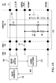
- Figure 1A shows an example charging system in either a private or a public location, comprising an EVSE 100 connected by a cordset 170 comprising a charging cable 140 and charging handle 150, to a power inlet of an EV 200, for charging the EV's rechargeable batteries.
- the EVSE's charging cable and charging handle provide AC charging current to the EV on high voltage conductor L1 and return conductor L2, which is converted to regulated direct current by a charger onboard the EV, for replenishing the charge of the rechargeable batteries.
- An equipment ground conductor G connects the non-current carrying metal parts of the EVSE to the chassis ground of the EV and provides a return path for current carried in the control pilot circuit.
- the EVSE generates a control pilot signal CP on control pilot line 115 of the charging cable and charging handle.
- the control pilot signal CP functions to verify that an EV is present and connected, permits energization/de-energization of the charging current, and provides a maximum available current rating to the EV.
- the rechargeable batteries power at least one electric motor to propel the EV, based on driver input to the EV's accelerator pedal.
- the invention provides temperature based protection in the cordset handle or charging handle 150 of the EVSE 100, with little or no modification required to EVSE control electronics 210 and minimal modification of the charging handle 150.
- the functional block diagram of Figure 1A illustrates an example EVSE 100 with an example embodiment of the charging handle temperature sensor 120 inside the charging handle or connector 150.
- the temperature sensor 120 includes a pair of series connected thermistor and resistor circuits.
- a first series connected circuit including thermistor R1-NTC and resistor R3 connects the high voltage conductor L1 to the ground conductor G.
- a second series connected circuit including thermistor R2-NTC and resistor R4 connects the return conductor L2 or N to the ground conductor G.
- a ground fault detector 160 in the EVSE 100 is tripped if either thermistor R1-NTC or R2-NTC senses an increased temperature and diverts current to the ground conductor G.
- thermistor R1-NTC in the first series connected circuit senses an increased temperature, it diverts a portion of the current in the high voltage conductor L1 to the ground conductor G, which causes the current in the return conductor L2 or N to be less than the current in the high voltage conductor L.
- This difference in the currents is detected by the ground fault detector 160.
- the ground fault detector 160 may be a conventional ground fault interrupter circuit designed to protect users from an electrical shock by interrupting the source of power on high voltage conductor L1 and return conductor L2, when there is a difference in the currents in these conductors.
- ground fault detector 160 when the ground fault detector 160 detects a difference in the currents in conductor L1 and conductor L2 or N, ground fault detector 160 outputs a detection signal to the control electronics 210, which then sends a tripping signal to the circuit interrupter 170, to thereby interrupt the source of power on conductor L1 and conductor L2.
- the ground fault detector 160 outputs a detection signal to the control electronics 210, which then sends a tripping signal to the circuit interrupter 170, to thereby interrupt the source of power on conductor L1 and conductor L2.
- thermistor R2-NTC in the second series connected circuit senses an increased temperature, it diverts a portion of the current in the return conductor L2 to the ground conductor G, which causes the current in the return conductor L2 or N to be less than the current in the high voltage conductor L. This difference in the currents is detected by the ground fault detector 160.
- the ground fault detector 160, control electronics 210, and circuit interrupter 170 components in the EVSE are existing components. Little or no modification is required to the EVSE to automatically shut down charging operations in response to a temperature increase in the charging handle. Temperature based protection within the charging handle is achieved without significant added cost or complexity and minimal modification of the handle.
- the EVSE 100 may operate based on the SAE J1772 standard, to provide 208 to 240 volt AC, single phase power for a maximum continuous current of 30 Amperes, on the high voltage conductor L1 and return conductor L2 of the EVSE cordset 170.
- the SAE J1772 standard specifies the control pilot signal CP functions on the control pilot line 115 of the EVSE cordset 170.
- the thermistors respond to temperature rise with lower resistance, resulting in some current from L1/L2 to ground.
- Regional standards require that the EVSE provide ground current detection and protection according to a trip curve with current response time characteristics. In the United States, for example, UL2231 requires, as one option, the EVSE disconnect the L1 and L2/N conductors if leakage to ground above a nominal threshold of 18-20mA is measured.
- the EVSE disconnect the L1 and L2/N conductors if leakage to ground above a nominal threshold of 18-20mA is measured.
- the invention reuses the function of ground current protection function provided by the EVSE to interrupt charging based on a chosen temperature.
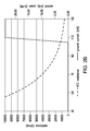
- Figure 1B is an example graph of measured ground current (mA), power dissipation in the thermistor (W), and negative temperature coefficient (NTC) thermistor resistance (Ohms) vs temperature, for the temperature sensor of Figure 1A .
- the NTC thermistor adds some power dissipation to the system, even during normal operation. It may be desirable to reduce the heating added by the thermistor.
- An alternative embodiment shown in Figure 2A adds an active component controlled by the thermistor resistance, to minimize power dissipation during normal operation.
- the functional block diagram of Figure 2A illustrates an example EVSE 100 with an example alternate embodiment of the charging handle temperature sensor 120 inside the charging handle or connector 150.
- the temperature sensor 120 includes a thermistor R1-NTC and a first resistor R2 connected in series between a control pilot conductor 115 and the ground conductor G.
- a thyristor Q1 and a second resistor R3 connect the high voltage conductor L1 to the ground conductor G.
- the gate of the thyristor Q1 is configured to receive a signal from the node between the thermistor R1-NTC and the resistor R2, causing the thyristor Q1 to divert current from the high voltage conductor L1, in response to the thermistor R1-NTC sensing an increase in temperature.
- the ground fault detector 160 in the EVSE 100 is thereby tripped when the thermistor R1-NTC senses an increased temperature. If thermistor R1-NTC senses an increased temperature, it diverts a portion of the current in the high voltage conductor L1 to the ground conductor G, which causes the current in the return conductor L2 or N to be less than the current in the high voltage conductor L. This difference in the currents is detected by the ground fault detector 160.
- Figure 2B is an example graph of measured ground current (mA) and negative temperature coefficient (NTC) thermistor resistance (Ohms) vs temperature, for the temperature sensor of Figure 2A .
- the control pilot signal specified in the SAE J1772 standard is a 1 kHz square wave signal in the range of +12 and -12 volts. Prior to the commencement of charging the EV, the control pilot signal uses its voltage to define the state of the charging transaction. If the control pilot signal is a steady voltage of +12 volts DC, this indicates State A, that an EV is not connected. If the control pilot is a 1 kHz square wave signal with positive voltage of +9 volts and negative voltage of -12 volts, this indicates State B, that an EV is connected, but is not ready to receive a charge.
- the SAE J1772 standard specifies that a control pilot 1 kHz square wave signal positive voltage of +6 volts and negative voltage of -12 volts indicates State C, that the EV is ready to accept charge.
- the signal is generated in the EVSE and the EV puts an impedance on the line and the voltage on control pilot drops. After detecting the control pilot signal in State C, the EVSE proceeds to deliver the charging current to the EV over its power lines L1 and L2.
- the thermistor R1-NTC in Figure 2A reduces its resistance, allowing a small current to flow through the series connected thermistor and resistor R2, thereby raising the voltage of the node between the thermistor and the resistor R2.
- the node is connected to the gate of the thyristor Q1. When the voltage on the gate rises above a threshold voltage, the thyristor Q1 becomes conductive.
- the gate of the thyristor Q1 is configured to receive the increased voltage as a signal from the node between the thermistor R1-NTC and the resistor R2, causing the thyristor Q1 to divert current from the high voltage conductor L1, in response to the thermistor R1-NTC sensing an increase in temperature.
- the ground fault detector 160 in the EVSE 100 is thereby tripped when the thermistor R1-NTC senses an increased temperature.
- the placement of the temperature sensor 120 determines the components in the handle which will be monitored for temperature based protection. Depending on the design of the EVSE cordset and charging handle, it may be desireable to detect temperature increases of a specific conductor or nonconducting part of the handle. Connecting the temperature sensor 120 thermally, but not electrically, to a specific part of interest, allows detection at the desired element in the handle.
- Figure 3 shows a temperature sensor with a pair of series connected thermistor, diode, and resistor circuits.
- a first series connected thermistor, diode, and resistor circuit connects the high voltage conductor to the ground conductor.
- a second series connected thermistor, diode, and resistor circuit connects the return conductor to the ground conductor.
- the ground fault detector in the EVSE is tripped if either thermistor senses an increased temperature and diverts current to the ground conductor.
- the diodes prevent currents in the two circuits from cancelling each other in the event that the thermistor resistances would be equal.
- the temperature sensor 120 includes a pair of series connected thermistor, diode, and resistor circuits.
- a first series connected thermistor R1-NTC, diode D1, and resistor R3 circuit connects the high voltage conductor L1 to the ground conductor.
- a second series connected thermistor R2-NTC, diode D2, and resistor R4 circuit connects the return conductor L2 to the ground conductor.
- the ground fault detector 160 in the EVSE 100 is tripped if either thermistor R1-NTC or R2-NTC senses an increased temperature and diverts current to the ground conductor.
- the diodes D1 and D2 prevent currents in the two circuits from cancelling each other in the event that the thermistor R1-NTC or R2-NTC resistances would be equal.
- the temperature based protection is provided without modification of the EVSE control electronics or firmware, by reusing the ground fault protection function already implemented in the EVSE.
- the invention may be implemented with the EVSE further modified to provide differentiation between the ground fault current signature of current leakage through personnel and through the temperature sensor circuit. Detecting the ground fault characteristics of the temperature sensor circuit allows the EVSE to take specific action in response to the temperature based protection function.
- the EVSE may reduce the charging rate offered to the EV to decrease resistive heating of conductors and contact points within the charging handle. This may allow the EV to continue charging, at a reduced rate, while reducing the temperature to within nominal limits.
- the EVSE may also completely discontinue charging the EV, and inhibit automatic reset of the ground fault interrupter.
- the EVSE may indicate the temperature rise problem to the user, or signal an undesired operating condition to the owner or operator of the EVSE to initiate maintenance of the cordset.
- the invention provides temperature based protection of hot spots within the EVSE handle without significant added cost or complexity.
- the invention makes novel reuse of existing infrastructure in the EVSE to achieve temperature based protection, with little or no modification required at the EVSE control electronics, and minimal modification required at the handle.
- the invention does not require significant additional infrastructure in the EVSE.
- Reusing the existing ground fault protection function of the EVSE minimizes the required modification of the EVSE to implement the invention and provide a temperature based protection.
- the invention may be implemented using the existing charging handle with a small hardware modification, using the existing cord without any modification, and using the existing EVSE without any hardware or firmware modification. The resulting invention reduces the chances of overheating and possibly melting the charging handle while the handle is fastened to the EV during charging operations.
Landscapes
- Engineering & Computer Science (AREA)
- Power Engineering (AREA)
- Transportation (AREA)
- Mechanical Engineering (AREA)
- Life Sciences & Earth Sciences (AREA)
- Sustainable Development (AREA)
- Sustainable Energy (AREA)
- Charge And Discharge Circuits For Batteries Or The Like (AREA)
- Emergency Protection Circuit Devices (AREA)
Abstract
Description
- The invention disclosed relates to electric vehicle supply equipment.
- Plug-in electric vehicles (EVs), including all-electric cars, neighborhood electric vehicles and plug-in hybrids, are becoming a popular mode for personal transportation, in part because they are less expensive to operate and have a reduced carbon footprint. Electric vehicle charging stations, also called Electric Vehicle Supply Equipment (EVSE), provide power to an EV through a standardized interface. The interface is defined by industry standard SAE J1772. The interface includes defined control signals, ground, and a high ampere current path. In the Level 2 alternating current (AC) charging standard, the EVSE may provide up to 80A charging current to the connected EV.
- The high ampere current path includes multiple junctions between conductors. The connection point between the cordset handle or charging handle of the EVSE and the receptacle of the EV is an example of a pin and socket junction. The construction of the EVSE charging handle commonly includes junctions that connect the wires of the cordset cable and the pins of the handle.
- These multiple junctions represent opportunities for resistive heating along the current path between the EVSE and EV. For example, with manufacturing tolerances, mechanical ageing and reduction of contact pressure, chemical corrosion or oxidation of mating surfaces, or misuse and abuse leading to degraded performance, the current path within the EVSE charging handle can become increasingly resistive. Increased resistance may lead to overheating and possibly melting the charging handle while the handle is fastened to the EV during charging operations.
- The present version of J1772 does not require any monitoring of the temperature in the current path, or any protection based on temperature increase along the current path. However, with the possibility of degraded performance at the junctions in the EVSE cordset caused by heating, it would be advantageous to provide temperature based protection, such as automatically shutting down charging operations in response to a temperature increase in the charging handle.
- Present solutions for temperature based protections within the EVSE charging handle require additional, dedicated connection components between a temperature measurement device and the EVSE electronics. These include using additional conductors within the EVSE cord beyond those specified by the J1772 standard, or alternately using a wireless data transmission from the measurement device in the handle to the electronics of the EVSE.
- The subject invention reduces the chances of overheating and possibly melting the charging handle while the handle is fastened to the EV during charging operations. The subject invention achieves the benefit of temperature based protection of the charging handle of an electric vehicle charging station or EVSE, without significant added cost or complexity. The invention utilizes existing components in the EVSE to achieve temperature based protection, with little or no modification required to the EVSE control electronics, and minimal modification required to the charging handle.
- The invention provides a temperature sensor in a charging handle of an EVSE. The temperature sensor automatically shuts down charging operations in response to a temperature increase in a charging handle of the EVSE. The temperature sensor is connected between a ground conductor and a high voltage conductor in the charging handle. The charging handle includes a return conductor. The temperature sensor includes a thermistor that changes its resistance in response to an increase in temperature in the charging handle. A portion of current in the high voltage conductor is diverted to the ground conductor, instead of the return conductor, in response to the thermistor sensing a temperature increase, thereby causing a standard ground fault detector to trip in the EVSE.
- In one example embodiment, the temperature sensor includes a pair of series connected thermistor and resistor circuits. A first series connected thermistor and resistor circuit connects the high voltage conductor to the ground conductor. A second series connected thermistor and resistor circuit connects the return conductor to the ground conductor. The ground fault detector in the EVSE is tripped if either thermistor senses an increased temperature and diverts current to the ground conductor.
- In another example embodiment, the temperature sensor includes a thermistor and a first resistor connected in series between a control pilot conductor and the ground conductor. A thyristor and a second resistor connect the high voltage conductor to the ground conductor. The gate of the thyristor is configured to receive a signal from the thermistor, causing the thyristor to divert current from the high voltage conductor, in response to the thermistor sensing an increase in temperature. The ground fault detector in the EVSE is thereby tripped when the thermistor senses an increased temperature.
- In still another example embodiment, the temperature sensor includes a pair of series connected thermistor, diode, and resistor circuits. A first series connected thermistor, diode, and resistor circuit connects the high voltage conductor to the ground conductor. A second series connected thermistor, diode, and resistor circuit connects the return conductor to the ground conductor. The ground fault detector in the EVSE is tripped if either thermistor senses an increased temperature and diverts current to the ground conductor. The diodes prevent currents in the two circuits from cancelling each other in the event that the thermistor resistances would be equal.
- The EVSE utilizes existing components, with little or no modification required to automatically shut down charging operations in response to a temperature increase in a charging handle. Temperature sensing within the charging handle is achieved without significant added cost or complexity and minimal modification of the handle. The chances of overheating and possibly melting the charging handle while the handle is fastened to the EV during charging operations are thus reduced.
-
-
Figure 1A shows a temperature sensor with a pair of series connected thermistor and resistor circuits. A first series connected thermistor and resistor circuit connects the high voltage conductor to the ground conductor. A second series connected thermistor and resistor circuit connects the return conductor to the ground conductor. The ground fault detector in the EVSE is tripped if either thermistor senses an increased temperature and diverts current to the ground conductor. -
Figure 1B is an example graph of measured ground current (mA), power dissipation in the thermistor (W), and negative temperature coefficient (NTC) thermistor resistance (Ohms) vs temperature, for the temperature sensor ofFigure 1A . -
Figure 2A shows a temperature sensor with a thermistor and a first resistor connected in series between a control pilot conductor and the ground conductor. A thyristor and a second resistor connect the high voltage conductor to the ground conductor. The gate of the thyristor is configured to receive a signal from the thermistor, causing the thyristor to divert current from the high voltage conductor, in response to the thermistor sensing an increase in temperature. The ground fault detector in the EVSE is thereby tripped when the thermistor senses an increased temperature. -
Figure 2B is an example graph of measured ground current (mA) and negative temperature coefficient (NTC) thermistor resistance (Ohms) vs temperature, for the temperature sensor ofFigure 2A . -
Figure 3 shows a temperature sensor with a pair of series connected thermistor, diode, and resistor circuits. A first series connected thermistor, diode, and resistor circuit connects the high voltage conductor to the ground conductor. A second series connected thermistor, diode, and resistor circuit connects the return conductor to the ground conductor. The ground fault detector in the EVSE is tripped if either thermistor senses an increased temperature and diverts current to the ground conductor. The diodes prevent currents in the two circuits from cancelling each other in the event that the thermistor resistances would be equal. -
Figure 1A shows an example charging system in either a private or a public location, comprising anEVSE 100 connected by acordset 170 comprising acharging cable 140 andcharging handle 150, to a power inlet of anEV 200, for charging the EV's rechargeable batteries. The EVSE's charging cable and charging handle provide AC charging current to the EV on high voltage conductor L1 and return conductor L2, which is converted to regulated direct current by a charger onboard the EV, for replenishing the charge of the rechargeable batteries. An equipment ground conductor G connects the non-current carrying metal parts of the EVSE to the chassis ground of the EV and provides a return path for current carried in the control pilot circuit. The EVSE generates a control pilot signal CP oncontrol pilot line 115 of the charging cable and charging handle. The control pilot signal CP functions to verify that an EV is present and connected, permits energization/de-energization of the charging current, and provides a maximum available current rating to the EV. The rechargeable batteries power at least one electric motor to propel the EV, based on driver input to the EV's accelerator pedal. - The invention provides temperature based protection in the cordset handle or charging
handle 150 of theEVSE 100, with little or no modification required toEVSE control electronics 210 and minimal modification of the charginghandle 150. - The functional block diagram of
Figure 1A illustrates anexample EVSE 100 with an example embodiment of the charginghandle temperature sensor 120 inside the charging handle orconnector 150. Thetemperature sensor 120 includes a pair of series connected thermistor and resistor circuits. A first series connected circuit including thermistor R1-NTC and resistor R3 connects the high voltage conductor L1 to the ground conductor G. A second series connected circuit including thermistor R2-NTC and resistor R4 connects the return conductor L2 or N to the ground conductor G. Aground fault detector 160 in theEVSE 100 is tripped if either thermistor R1-NTC or R2-NTC senses an increased temperature and diverts current to the ground conductor G. - If thermistor R1-NTC in the first series connected circuit, senses an increased temperature, it diverts a portion of the current in the high voltage conductor L1 to the ground conductor G, which causes the current in the return conductor L2 or N to be less than the current in the high voltage conductor L. This difference in the currents is detected by the
ground fault detector 160. Theground fault detector 160 may be a conventional ground fault interrupter circuit designed to protect users from an electrical shock by interrupting the source of power on high voltage conductor L1 and return conductor L2, when there is a difference in the currents in these conductors. In an example embodiment, when theground fault detector 160 detects a difference in the currents in conductor L1 and conductor L2 or N,ground fault detector 160 outputs a detection signal to thecontrol electronics 210, which then sends a tripping signal to thecircuit interrupter 170, to thereby interrupt the source of power on conductor L1 and conductor L2. Theground fault detector 160 outputs a detection signal to thecontrol electronics 210, which then sends a tripping signal to thecircuit interrupter 170, to thereby interrupt the source of power on conductor L1 and conductor L2. - If thermistor R2-NTC in the second series connected circuit, senses an increased temperature, it diverts a portion of the current in the return conductor L2 to the ground conductor G, which causes the current in the return conductor L2 or N to be less than the current in the high voltage conductor L. This difference in the currents is detected by the
ground fault detector 160. - The
ground fault detector 160,control electronics 210, andcircuit interrupter 170 components in the EVSE are existing components. Little or no modification is required to the EVSE to automatically shut down charging operations in response to a temperature increase in the charging handle. Temperature based protection within the charging handle is achieved without significant added cost or complexity and minimal modification of the handle. - The
EVSE 100 may operate based on the SAE J1772 standard, to provide 208 to 240 volt AC, single phase power for a maximum continuous current of 30 Amperes, on the high voltage conductor L1 and return conductor L2 of theEVSE cordset 170. The SAE J1772 standard specifies the control pilot signal CP functions on thecontrol pilot line 115 of theEVSE cordset 170. - The thermistors respond to temperature rise with lower resistance, resulting in some current from L1/L2 to ground. Regional standards require that the EVSE provide ground current detection and protection according to a trip curve with current response time characteristics. In the United States, for example, UL2231 requires, as one option, the EVSE disconnect the L1 and L2/N conductors if leakage to ground above a nominal threshold of 18-20mA is measured. By choosing the appropriate NTC thermistor and series current limiting resistor values, the ground current through the thermistors and current limiting resistors will cross above this threshold at a specific temperature. In this way, the invention reuses the function of ground current protection function provided by the EVSE to interrupt charging based on a chosen temperature.
- The following table and the chart of
Figure 1B show an example implementation of the invention inFigure 1A , and the ground current through the thermistors is determined by the temperature.temp. (C) NTC resistance ground current (mA) power (0.1W) in NTC 25 200000 0.59 0.69 30 170000 0.69 0.81 40 119000 0.98 1.13 50 83300 1.37 1.57 60 58310 1.93 2.16 70 40817 2.68 2.93 80 28572 3.68 3.88 90 20000 5.00 5.00 95 17000 5.71 5.55 100 14450 6.50 6.11 105 12283 7.37 6.67 110 10440 8.31 7.21 115 8874 9.32 7.71 120 7543 10.40 8.15 125 6412 11.53 8.52 130 5450 12.70 8.79 135 4632 13.90 8.95 140 3938 15.12 9.00 145 3347 16.33 8.93 150 2845 17.53 8.74 -
Figure 1B is an example graph of measured ground current (mA), power dissipation in the thermistor (W), and negative temperature coefficient (NTC) thermistor resistance (Ohms) vs temperature, for the temperature sensor ofFigure 1A . As the example inFigure 1B shows, the NTC thermistor adds some power dissipation to the system, even during normal operation. It may be desirable to reduce the heating added by the thermistor. An alternative embodiment shown inFigure 2A adds an active component controlled by the thermistor resistance, to minimize power dissipation during normal operation. - The functional block diagram of
Figure 2A illustrates anexample EVSE 100 with an example alternate embodiment of the charginghandle temperature sensor 120 inside the charging handle orconnector 150. Thetemperature sensor 120 includes a thermistor R1-NTC and a first resistor R2 connected in series between acontrol pilot conductor 115 and the ground conductor G. A thyristor Q1 and a second resistor R3 connect the high voltage conductor L1 to the ground conductor G. The gate of the thyristor Q1 is configured to receive a signal from the node between the thermistor R1-NTC and the resistor R2, causing the thyristor Q1 to divert current from the high voltage conductor L1, in response to the thermistor R1-NTC sensing an increase in temperature. Theground fault detector 160 in theEVSE 100 is thereby tripped when the thermistor R1-NTC senses an increased temperature. If thermistor R1-NTC senses an increased temperature, it diverts a portion of the current in the high voltage conductor L1 to the ground conductor G, which causes the current in the return conductor L2 or N to be less than the current in the high voltage conductor L. This difference in the currents is detected by theground fault detector 160. - The following table and chart in
Figure 2B show the thermistor resistance, ground current and added power dissipation with the example embodiment.temp. (C) NTC resistance V thyristor gate ground current (mA) power dissipation (W) 25 200000 0.04 0.00 0 30 170000 0.05 0.00 0 40 119000 0.08 0.00 0 50 83300 0.11 0.00 0 60 58310 0.15 0.00 0 70 40817 0.22 0.00 0 80 28572 0.31 0.00 0 90 20000 0.43 0.00 0 95 17000 0.51 0.00 0 100 14450 0.59 0.00 0 105 12283 0.69 0.00 0 110 10440 0.80 23.80 2.856 115 8874 0.94 23.80 2.856 120 7543 1.09 23.80 2.856 125 6412 1.26 23.80 2.856 130 5450 1.45 23.80 2.856 -
Figure 2B is an example graph of measured ground current (mA) and negative temperature coefficient (NTC) thermistor resistance (Ohms) vs temperature, for the temperature sensor ofFigure 2A . - The control pilot signal specified in the SAE J1772 standard is a 1 kHz square wave signal in the range of +12 and -12 volts. Prior to the commencement of charging the EV, the control pilot signal uses its voltage to define the state of the charging transaction. If the control pilot signal is a steady voltage of +12 volts DC, this indicates State A, that an EV is not connected. If the control pilot is a 1 kHz square wave signal with positive voltage of +9 volts and negative voltage of -12 volts, this indicates State B, that an EV is connected, but is not ready to receive a charge. The SAE J1772 standard specifies that a
control pilot 1 kHz square wave signal positive voltage of +6 volts and negative voltage of -12 volts indicates State C, that the EV is ready to accept charge. The signal is generated in the EVSE and the EV puts an impedance on the line and the voltage on control pilot drops. After detecting the control pilot signal in State C, the EVSE proceeds to deliver the charging current to the EV over its power lines L1 and L2. - During the charging of the EV, if the temperature in the charging handle 150 increases, the thermistor R1-NTC in
Figure 2A reduces its resistance, allowing a small current to flow through the series connected thermistor and resistor R2, thereby raising the voltage of the node between the thermistor and the resistor R2. The node is connected to the gate of the thyristor Q1. When the voltage on the gate rises above a threshold voltage, the thyristor Q1 becomes conductive. The gate of the thyristor Q1 is configured to receive the increased voltage as a signal from the node between the thermistor R1-NTC and the resistor R2, causing the thyristor Q1 to divert current from the high voltage conductor L1, in response to the thermistor R1-NTC sensing an increase in temperature. Theground fault detector 160 in theEVSE 100 is thereby tripped when the thermistor R1-NTC senses an increased temperature. - The placement of the
temperature sensor 120 determines the components in the handle which will be monitored for temperature based protection. Depending on the design of the EVSE cordset and charging handle, it may be desireable to detect temperature increases of a specific conductor or nonconducting part of the handle. Connecting thetemperature sensor 120 thermally, but not electrically, to a specific part of interest, allows detection at the desired element in the handle. -
Figure 3 shows a temperature sensor with a pair of series connected thermistor, diode, and resistor circuits. A first series connected thermistor, diode, and resistor circuit connects the high voltage conductor to the ground conductor. A second series connected thermistor, diode, and resistor circuit connects the return conductor to the ground conductor. The ground fault detector in the EVSE is tripped if either thermistor senses an increased temperature and diverts current to the ground conductor. The diodes prevent currents in the two circuits from cancelling each other in the event that the thermistor resistances would be equal. - The
temperature sensor 120 includes a pair of series connected thermistor, diode, and resistor circuits. A first series connected thermistor R1-NTC, diode D1, and resistor R3 circuit connects the high voltage conductor L1 to the ground conductor. A second series connected thermistor R2-NTC, diode D2, and resistor R4 circuit connects the return conductor L2 to the ground conductor. Theground fault detector 160 in theEVSE 100 is tripped if either thermistor R1-NTC or R2-NTC senses an increased temperature and diverts current to the ground conductor. The diodes D1 and D2 prevent currents in the two circuits from cancelling each other in the event that the thermistor R1-NTC or R2-NTC resistances would be equal. - In an example embodiment, the temperature based protection is provided without modification of the EVSE control electronics or firmware, by reusing the ground fault protection function already implemented in the EVSE. In an alternate example embodiment, the invention may be implemented with the EVSE further modified to provide differentiation between the ground fault current signature of current leakage through personnel and through the temperature sensor circuit. Detecting the ground fault characteristics of the temperature sensor circuit allows the EVSE to take specific action in response to the temperature based protection function.The EVSE may reduce the charging rate offered to the EV to decrease resistive heating of conductors and contact points within the charging handle. This may allow the EV to continue charging, at a reduced rate, while reducing the temperature to within nominal limits. The EVSE may also completely discontinue charging the EV, and inhibit automatic reset of the ground fault interrupter. The EVSE may indicate the temperature rise problem to the user, or signal an undesired operating condition to the owner or operator of the EVSE to initiate maintenance of the cordset.
- The invention provides temperature based protection of hot spots within the EVSE handle without significant added cost or complexity. The invention makes novel reuse of existing infrastructure in the EVSE to achieve temperature based protection, with little or no modification required at the EVSE control electronics, and minimal modification required at the handle. The invention does not require significant additional infrastructure in the EVSE. Reusing the existing ground fault protection function of the EVSE minimizes the required modification of the EVSE to implement the invention and provide a temperature based protection. The invention may be implemented using the existing charging handle with a small hardware modification, using the existing cord without any modification, and using the existing EVSE without any hardware or firmware modification. The resulting invention reduces the chances of overheating and possibly melting the charging handle while the handle is fastened to the EV during charging operations.
- Although specific example embodiments of the invention have been disclosed, persons of skill in the art will appreciate that changes may be made to the details described for the specific example embodiments, without departing from the spirit and the scope of the invention.
Claims (5)
- A circuit for automatic shutdown of charging operations in response to a temperature increase in a charging handle of an electric vehicle charging station, comprising:a temperature sensor connected between a ground conductor and a high voltage conductor in a charging handle of an electric vehicle charging station, the charging handle including a return conductor, wherein when the temperature sensor is exposed to an increase in temperature in the charging handle, a portion of current in the high voltage conductor flows to the ground conductor, instead of the return conductor, thereby causing a ground fault detector to trip in the charging station.
- The circuit for automatic shutdown of charging operations in response to a temperature increase in a charging handle of an electric vehicle charging station of claim 1, further comprising:a thermistor in the temperature sensor, the thermistor being configured to change its resistance in response to an increase in temperature in the charging handle, thereby causing the portion of current in the high voltage conductor to flow to the ground conductor, instead of the return conductor.
- The circuit for automatic shutdown of charging operations in response to a temperature increase in a charging handle of an electric vehicle charging station of claim 1, further comprising:a thermistor and a resistor in the temperature sensor, the thermistor and resistor connected in series between the high voltage conductor and the ground conductor in the charging handle of the electric vehicle charging station, the thermistor being configured to reduce its resistance in response to an increase in temperature in the charging handle, thereby causing the portion of current in the high voltage conductor to flow through the thermistor and the resistor to the ground conductor, instead of the return conductor.
- The circuit for automatic shutdown of charging operations in response to a temperature increase in a charging handle of an electric vehicle charging station of claim 1, further comprising:a thermistor and a first resistor in the temperature sensor, the thermistor and first resistor connected in series between a control pilot conductor and the ground conductor in the charging handle of the electric vehicle charging station, the thermistor being configured to change its resistance in response to an increase in temperature in the charging handle, thereby causing a voltage to change at a node between the thermistor and the first resistor; anda thyristor and a second resistor in the temperature sensor, the thyristor and second resistor connected in series between the high voltage conductor and the ground conductor in the charging handle of the electric vehicle charging station, the thyristor having a gate electrode connected to the node between the thermistor and the first resistor so that a voltage at the node between the thermistor and the first resistor is applied to the gate, the thyristor being configured to become conductive in response to a voltage on its gate reaching a threshold voltage, the thyristor thereby conducting the portion of current in the high voltage conductor to flow through the thyristor and second resistor to the ground conductor, instead of the return conductor, in response to the increase in temperature in the charging handle.
- The circuit for automatic shutdown of charging operations in response to a temperature increase in a charging handle of an electric vehicle charging station of claim 1, further comprising:a first thermistor, a first diode, and a first resistor in the temperature sensor, the first thermistor, first diode, and first resistor connected in series between the high voltage conductor and the ground conductor in the charging handle of the electric vehicle charging station, the first thermistor being configured to reduce its resistance in response to an increase in temperature in the charging handle, thereby causing the portion of current in the high voltage conductor to flow through the first thermistor, the first diode, and the first resistor to the ground conductor, instead of the return conductor, thereby causing a ground fault detector to trip in the charging station; anda second thermistor, a second diode, and a second resistor in the temperature sensor, the second thermistor, second diode, and second resistor connected in series between the return conductor and the ground conductor in the charging handle of the electric vehicle charging station, the second thermistor being configured to reduce its resistance in response to an increase in temperature in the charging handle, thereby causing a portion of current in the return conductor to flow through the second thermistor, the second diode, and the second resistor to the ground conductor, instead of the high voltage conductor, thereby causing the ground fault detector to trip in the charging station.
Applications Claiming Priority (1)
| Application Number | Priority Date | Filing Date | Title |
|---|---|---|---|
| US14/546,334 US9707850B2 (en) | 2014-11-18 | 2014-11-18 | EVSE handle with automatic thermal shut down by NTC to ground |
Publications (2)
| Publication Number | Publication Date |
|---|---|
| EP3025902A1 true EP3025902A1 (en) | 2016-06-01 |
| EP3025902B1 EP3025902B1 (en) | 2023-05-17 |
Family
ID=54478606
Family Applications (1)
| Application Number | Title | Priority Date | Filing Date |
|---|---|---|---|
| EP15193312.4A Active EP3025902B1 (en) | 2014-11-18 | 2015-11-05 | Evse handle with automatic thermal shut down by ntc to ground |
Country Status (4)
| Country | Link |
|---|---|
| US (1) | US9707850B2 (en) |
| EP (1) | EP3025902B1 (en) |
| CN (1) | CN105610124B (en) |
| MX (1) | MX350107B (en) |
Cited By (2)
| Publication number | Priority date | Publication date | Assignee | Title |
|---|---|---|---|---|
| EP3246196A1 (en) * | 2016-05-18 | 2017-11-22 | Delta Electronics, Inc. | Charge gun and electric vehicle charging method |
| WO2022037842A1 (en) * | 2020-08-17 | 2022-02-24 | Bayerische Motoren Werke Aktiengesellschaft | Plug-in connection element, and a device for monitoring a plug-in connection element |
Families Citing this family (17)
| Publication number | Priority date | Publication date | Assignee | Title |
|---|---|---|---|---|
| US9804034B2 (en) * | 2014-11-14 | 2017-10-31 | Schneider Electric USA, Inc. | EVSE with cordset handle temperature measurement |
| CN107407704B (en) * | 2015-03-23 | 2021-05-18 | 伟巴斯特充电系统公司 | System for monitoring power connector and cable health |
| US12275308B1 (en) | 2015-09-25 | 2025-04-15 | Evercharge, Inc. | Electric vehicle supply equipment (EVSE) having internal current overage protection, and associated charging methods for multi-type electric vehicles and non-electric vehicle devices |
| US10183586B1 (en) | 2015-09-25 | 2019-01-22 | Evercharge, Inc. | Mixed-level electric vehicle supply equipment (EVSE) and associated charging methods for multi-type electric vehicles and non-electric vehicle devices |
| US11046186B1 (en) * | 2015-09-25 | 2021-06-29 | Evercharge, Inc. | Electric vehicle supply equipment (EVSE) having internal current overage protection, and associated charging methods for multi-type electric vehicles and non-electric vehicle |
| US11091054B1 (en) | 2018-03-14 | 2021-08-17 | Evercharge, Inc. | Smart load management apparatus and system for electric vehicle charging |
| FR3048387B1 (en) * | 2016-03-02 | 2019-06-21 | Alstom Transport Technologies | IMPROVED RECHARGE INSTALLATION BY CONDUCTING A VEHICLE |
| CN107404132B (en) * | 2016-05-18 | 2021-06-04 | 台达电子工业股份有限公司 | Charging gun and electric vehicle charging equipment |
| EP3582996A4 (en) * | 2017-02-15 | 2021-01-13 | Webasto Charging Systems, Inc. | THERMAL MANAGEMENT OF ELECTRIC VEHICLE COUPLER CONTACTS |
| CN207265713U (en) * | 2017-07-28 | 2018-04-20 | 特斯拉公司 | Charging system with thermal protection |
| US10768054B2 (en) | 2017-11-29 | 2020-09-08 | Te Connectivity Corporation | Temperature sensing electrical device |
| US12099084B2 (en) * | 2018-04-17 | 2024-09-24 | Maxim Integrated Products, Inc. | Systems and methods for real-time fault detection |
| US11186191B2 (en) * | 2018-12-07 | 2021-11-30 | Delta Electronics, Inc. | Charging device for electric vehicle |
| KR101996603B1 (en) * | 2018-12-19 | 2019-07-04 | 중앙제어 주식회사 | Apparatus for Sensing Temperature of Electric Vehicle Charger |
| CN112687866B (en) * | 2019-10-18 | 2025-02-18 | Ecoprobm有限公司 | Lithium secondary battery positive electrode active material, preparation method thereof and lithium secondary battery containing the same |
| US11472301B2 (en) * | 2020-08-10 | 2022-10-18 | Webasto Charging Systems, Inc. | Method and system for temperature regulation for a portable charger |
| CN118857499A (en) * | 2024-09-11 | 2024-10-29 | 卡图电子(昆山)有限公司 | A temperature sensing device with self-protection |
Citations (5)
| Publication number | Priority date | Publication date | Assignee | Title |
|---|---|---|---|---|
| US20090167537A1 (en) * | 2007-12-28 | 2009-07-02 | Feliss Norbert A | Minimizing electrical outlet safety failures due to over temperature condition |
| US20090316321A1 (en) * | 2008-06-18 | 2009-12-24 | Gm Global Technology Operations, Inc. | Thermal security for hybrid vehicle recharging cable plugs device and method |
| DE102009034886A1 (en) * | 2009-07-27 | 2011-02-03 | Rwe Ag | Charging cable plug for connecting an electric vehicle to a charging station |
| WO2012129104A1 (en) * | 2011-03-18 | 2012-09-27 | Aerovironment, Inc. | Electric vehicle supply equipment with temperature-controlled current |
| WO2014155947A1 (en) * | 2013-03-29 | 2014-10-02 | パナソニック株式会社 | Connector for electrical connection |
Family Cites Families (49)
| Publication number | Priority date | Publication date | Assignee | Title |
|---|---|---|---|---|
| US2991397A (en) | 1957-10-31 | 1961-07-04 | Femco Inc | Protective system for detecting breakdown resistance that would cause a short or ground of a power circuit |
| US3947759A (en) | 1974-09-16 | 1976-03-30 | Continental Engineering, Inc. | Leakage current monitoring system and method |
| JPH0630505A (en) | 1992-01-31 | 1994-02-04 | Fuji Electric Co Ltd | Electric system for electric automobile |
| US5351005A (en) | 1992-12-31 | 1994-09-27 | Honeywell Inc. | Resetting closed-loop magnetoresistive magnetic sensor |
| US5548200A (en) | 1994-07-06 | 1996-08-20 | Norvik Traction Inc. | Universal charging station and method for charging electric vehicle batteries |
| US6510793B1 (en) | 2001-06-28 | 2003-01-28 | Eastman Kodak Company | Imaging apparatus and printing plate mounting surface for use in an imaging apparatus having printing plate registration detection |
| CN2884639Y (en) * | 2005-11-25 | 2007-03-28 | 神讯电脑(昆山)有限公司 | Overheat protection circuit |
| US20080103552A1 (en) | 2006-10-31 | 2008-05-01 | Medtronic, Inc. | Controller for obtaining prescriptive analysis of functionality of implantable medical device leads, system and method therefore |
| JP4479768B2 (en) | 2007-09-10 | 2010-06-09 | トヨタ自動車株式会社 | Automobile and auto charging method |
| JP4453741B2 (en) | 2007-10-25 | 2010-04-21 | トヨタ自動車株式会社 | Electric vehicle and vehicle power supply device |
| JP4254894B1 (en) | 2007-11-29 | 2009-04-15 | トヨタ自動車株式会社 | Charging system and operating method thereof |
| EP2281333A2 (en) | 2008-04-09 | 2011-02-09 | Intellon Corporation | Transmission line directional awareness |
| EP2332771A4 (en) | 2008-09-22 | 2014-06-18 | Toyota Motor Co Ltd | ANOMALY DETECTOR OF A VEHICLE AND VEHICLE |
| US8106627B1 (en) | 2008-12-15 | 2012-01-31 | Comverge, Inc. | Method and system for co-operative charging of electric vehicles |
| US8781809B2 (en) | 2009-03-31 | 2014-07-15 | Gridpoint, Inc. | Software modeling systems for metering and translating measurements |
| EP2447106A4 (en) | 2009-06-24 | 2016-12-21 | Toyota Motor Co Ltd | CHARGE CONTROL DEVICE FOR ELECTRIC VEHICLE |
| US8013570B2 (en) | 2009-07-23 | 2011-09-06 | Coulomb Technologies, Inc. | Electrical circuit sharing for electric vehicle charging stations |
| US8890473B2 (en) | 2009-07-28 | 2014-11-18 | Bosch Automotive Service Solutions Llc | Sequential charging of multiple electric vehicles |
| US8498087B2 (en) | 2009-11-03 | 2013-07-30 | Apple Inc. | Thermal protection circuits for electronic device cables |
| JP5182434B2 (en) | 2009-11-26 | 2013-04-17 | トヨタ自動車株式会社 | Charger |
| US20110169447A1 (en) | 2010-01-11 | 2011-07-14 | Leviton Manufacturing Co., Inc. | Electric vehicle supply equipment |
| US8558504B2 (en) | 2010-01-11 | 2013-10-15 | Leviton Manufacturing Co., Inc. | Electric vehicle supply equipment with timer |
| US9156362B2 (en) | 2010-04-09 | 2015-10-13 | Aerovironment, Inc. | Portable charging cable with in-line controller |
| US8981716B2 (en) | 2010-08-09 | 2015-03-17 | Control Module, Inc. | Power share system for electric vehicle service equipment |
| WO2012099978A2 (en) * | 2011-01-19 | 2012-07-26 | Aerovironment, Inc. | Electric vehicle docking connector with embedded evse controller |
| WO2012122310A1 (en) | 2011-03-08 | 2012-09-13 | Trilliant Networks, Inc. | System and method for managing load distribution across a power grid |
| US9008992B2 (en) | 2011-03-25 | 2015-04-14 | Thomas & Betts International, Inc. | Testing and monitoring an electrical system |
| DE102011084362B4 (en) | 2011-03-30 | 2015-03-05 | Bender Gmbh & Co. Kg | Electrical protection and monitoring device in an electric vehicle for safe driving and safe charging and regenerative operation of the electric vehicle at a charging station |
| FR2973962B1 (en) | 2011-04-06 | 2013-05-31 | Peugeot Citroen Automobiles Sa | CHARGE SYSTEM FOR AN ELECTRIC OR HYBRID VEHICLE |
| US8731730B2 (en) | 2011-04-27 | 2014-05-20 | Ev Patent Holdings, Llc | Electric vehicle clustered charge distribution and prioritization method, system and apparatus |
| US8587911B2 (en) | 2011-05-12 | 2013-11-19 | Control Module, Inc. | Service line safety monitor |
| JP5796387B2 (en) | 2011-07-21 | 2015-10-21 | 日立金属株式会社 | Vehicle charging device and vehicle charging system |
| JP5758746B2 (en) | 2011-08-30 | 2015-08-05 | トヨタ自動車株式会社 | Power supply connector, vehicle, and vehicle control method |
| US8810198B2 (en) | 2011-09-02 | 2014-08-19 | Tesla Motors, Inc. | Multiport vehicle DC charging system with variable power distribution according to power distribution rules |
| JP6185472B2 (en) | 2011-09-09 | 2017-08-23 | ワイトリシティ コーポレーションWitricity Corporation | Foreign object detection in wireless energy transmission systems |
| DE102011084527A1 (en) | 2011-10-14 | 2013-04-18 | Siemens Aktiengesellschaft | Charging infrastructure for electric vehicles |
| US9233611B2 (en) | 2011-11-10 | 2016-01-12 | Lear Corporation | Proximity detection circuit having short protection |
| JP5517313B2 (en) | 2011-12-28 | 2014-06-11 | 株式会社豊田自動織機 | Vehicle charging system |
| IL218213A0 (en) | 2012-02-20 | 2012-07-31 | Better Place GmbH | Charging management method and system |
| US8929069B2 (en) | 2012-05-31 | 2015-01-06 | Bosch Automotive Service Solutions Llc | Electric vehicle charging system with robustness features and universal port |
| US9148027B2 (en) | 2012-07-30 | 2015-09-29 | General Electric Company | Method and system for charging of electric vehicles |
| WO2014036013A2 (en) | 2012-08-27 | 2014-03-06 | Aerovironment, Inc. | Portable electric vehicle supply equipment |
| JP6098007B2 (en) * | 2012-09-28 | 2017-03-22 | パナソニックIpマネジメント株式会社 | Connector for electrical connection |
| CN202905642U (en) * | 2012-10-29 | 2013-04-24 | 山东开泰石化股份有限公司 | Lightning protection leakage circuit breaker |
| JP5672356B2 (en) | 2012-12-21 | 2015-02-18 | 株式会社デンソー | Charging cable device |
| DE102013005507A1 (en) | 2013-04-02 | 2014-10-02 | Rwe Ag | Method for operating a charging station |
| KR101610102B1 (en) | 2014-04-14 | 2016-04-08 | 현대자동차 주식회사 | Slow charge method and on-board charger for environmentally-friendly vehicle |
| KR20160031809A (en) | 2014-09-15 | 2016-03-23 | 엘에스산전 주식회사 | Electic automobile recharge apparatus |
| KR20160033512A (en) | 2014-09-18 | 2016-03-28 | 엘에스산전 주식회사 | Cable installment type charging control apparatus and method thereof |
-
2014
- 2014-11-18 US US14/546,334 patent/US9707850B2/en active Active
-
2015
- 2015-10-27 MX MX2015014994A patent/MX350107B/en active IP Right Grant
- 2015-11-05 EP EP15193312.4A patent/EP3025902B1/en active Active
- 2015-11-18 CN CN201510796047.8A patent/CN105610124B/en active Active
Patent Citations (5)
| Publication number | Priority date | Publication date | Assignee | Title |
|---|---|---|---|---|
| US20090167537A1 (en) * | 2007-12-28 | 2009-07-02 | Feliss Norbert A | Minimizing electrical outlet safety failures due to over temperature condition |
| US20090316321A1 (en) * | 2008-06-18 | 2009-12-24 | Gm Global Technology Operations, Inc. | Thermal security for hybrid vehicle recharging cable plugs device and method |
| DE102009034886A1 (en) * | 2009-07-27 | 2011-02-03 | Rwe Ag | Charging cable plug for connecting an electric vehicle to a charging station |
| WO2012129104A1 (en) * | 2011-03-18 | 2012-09-27 | Aerovironment, Inc. | Electric vehicle supply equipment with temperature-controlled current |
| WO2014155947A1 (en) * | 2013-03-29 | 2014-10-02 | パナソニック株式会社 | Connector for electrical connection |
Cited By (3)
| Publication number | Priority date | Publication date | Assignee | Title |
|---|---|---|---|---|
| EP3246196A1 (en) * | 2016-05-18 | 2017-11-22 | Delta Electronics, Inc. | Charge gun and electric vehicle charging method |
| US10227014B2 (en) | 2016-05-18 | 2019-03-12 | Delta Electronics, Inc. | Charge gun, electric vehicle supply equipment, and electric vehicle charging method thereof |
| WO2022037842A1 (en) * | 2020-08-17 | 2022-02-24 | Bayerische Motoren Werke Aktiengesellschaft | Plug-in connection element, and a device for monitoring a plug-in connection element |
Also Published As
| Publication number | Publication date |
|---|---|
| US9707850B2 (en) | 2017-07-18 |
| MX350107B (en) | 2017-08-28 |
| EP3025902B1 (en) | 2023-05-17 |
| US20160137079A1 (en) | 2016-05-19 |
| CN105610124B (en) | 2021-03-05 |
| MX2015014994A (en) | 2016-05-17 |
| CN105610124A (en) | 2016-05-25 |
Similar Documents
| Publication | Publication Date | Title |
|---|---|---|
| EP3025902B1 (en) | Evse handle with automatic thermal shut down by ntc to ground | |
| EP3021098B1 (en) | Evse with cordset handle temperature measurement | |
| US8723477B2 (en) | Charging cable connector for connecting an electric vehicle to a charging station | |
| US9114715B2 (en) | Electronic control unit | |
| US9634435B1 (en) | Electric vehicle power supply equipment with interchangeable power supply cords conforming to different technical standards | |
| US20180050599A1 (en) | Thermally Monitored Charging Device | |
| US8922967B2 (en) | Thermal protection system for electrical device | |
| JP5369833B2 (en) | Electric vehicle charger and ground fault detection method | |
| CN109562693B (en) | Device for charging electric vehicle and method of verifying contact between device for charging electric vehicle and electric vehicle | |
| US20150171646A1 (en) | Temperature monitoring hev charger cord assembly and charging method | |
| CN106936177B (en) | Charging device and charging method for a high-voltage battery of a motor vehicle | |
| US20170334300A1 (en) | Charging System with Temperature Sensor | |
| KR102657722B1 (en) | Apparatus for detecting ground error and method thereof | |
| US20220376525A1 (en) | Temperature monitored charging connector part | |
| US20190375299A1 (en) | Dual temperature-monitoring hev charger cord and adapter assembly | |
| JP5837078B2 (en) | Apparatus and method for estimating contact current and protecting electrical equipment from the contact current | |
| CN104487277B (en) | Method for protecting charging line and charging device | |
| US9321360B2 (en) | Electronic control unit | |
| CN212685263U (en) | Charging plugs and charging stations for charging electric vehicles | |
| CN110488111B (en) | Method for controlling a charging process of an electric vehicle and charging cable | |
| KR20250085395A (en) | Electric vehicle charging controller and charging control method of the same | |
| US20250170911A1 (en) | Conversion adapter | |
| CN116194326A (en) | Plug connection element and device for monitoring plug connection element |
Legal Events
| Date | Code | Title | Description |
|---|---|---|---|
| PUAI | Public reference made under article 153(3) epc to a published international application that has entered the european phase |
Free format text: ORIGINAL CODE: 0009012 |
|
| AK | Designated contracting states |
Kind code of ref document: A1 Designated state(s): AL AT BE BG CH CY CZ DE DK EE ES FI FR GB GR HR HU IE IS IT LI LT LU LV MC MK MT NL NO PL PT RO RS SE SI SK SM TR |
|
| AX | Request for extension of the european patent |
Extension state: BA ME |
|
| STAA | Information on the status of an ep patent application or granted ep patent |
Free format text: STATUS: REQUEST FOR EXAMINATION WAS MADE |
|
| RIN1 | Information on inventor provided before grant (corrected) |
Inventor name: EDWARDS, BENJAMIN W. Inventor name: WHITE, MATTHEW L. Inventor name: FILIPPENKO, KONSTANTIN A. Inventor name: WEILER, RICHARD K. Inventor name: JEFFERIES, KEVIN M. |
|
| 17P | Request for examination filed |
Effective date: 20161123 |
|
| RBV | Designated contracting states (corrected) |
Designated state(s): AL AT BE BG CH CY CZ DE DK EE ES FI FR GB GR HR HU IE IS IT LI LT LU LV MC MK MT NL NO PL PT RO RS SE SI SK SM TR |
|
| STAA | Information on the status of an ep patent application or granted ep patent |
Free format text: STATUS: EXAMINATION IS IN PROGRESS |
|
| 17Q | First examination report despatched |
Effective date: 20201014 |
|
| REG | Reference to a national code |
Ref country code: DE Ref legal event code: R079 Free format text: PREVIOUS MAIN CLASS: B60L0011180000 Ipc: B60L0053000000 Ref country code: DE Ref legal event code: R079 Ref document number: 602015083606 Country of ref document: DE Free format text: PREVIOUS MAIN CLASS: B60L0011180000 Ipc: B60L0053000000 |
|
| GRAP | Despatch of communication of intention to grant a patent |
Free format text: ORIGINAL CODE: EPIDOSNIGR1 |
|
| STAA | Information on the status of an ep patent application or granted ep patent |
Free format text: STATUS: GRANT OF PATENT IS INTENDED |
|
| RIC1 | Information provided on ipc code assigned before grant |
Ipc: H02H 5/04 20060101ALI20221128BHEP Ipc: H02H 3/02 20060101ALI20221128BHEP Ipc: B60L 3/04 20060101ALI20221128BHEP Ipc: B60L 3/00 20060101ALI20221128BHEP Ipc: B60L 53/30 20190101ALI20221128BHEP Ipc: B60L 53/18 20190101ALI20221128BHEP Ipc: B60L 53/16 20190101ALI20221128BHEP Ipc: B60L 53/14 20190101ALI20221128BHEP Ipc: B60L 53/00 20190101AFI20221128BHEP |
|
| INTG | Intention to grant announced |
Effective date: 20221213 |
|
| GRAS | Grant fee paid |
Free format text: ORIGINAL CODE: EPIDOSNIGR3 |
|
| GRAA | (expected) grant |
Free format text: ORIGINAL CODE: 0009210 |
|
| STAA | Information on the status of an ep patent application or granted ep patent |
Free format text: STATUS: THE PATENT HAS BEEN GRANTED |
|
| RAP3 | Party data changed (applicant data changed or rights of an application transferred) |
Owner name: SCHNEIDER ELECTRIC USA, INC. |
|
| AK | Designated contracting states |
Kind code of ref document: B1 Designated state(s): AL AT BE BG CH CY CZ DE DK EE ES FI FR GB GR HR HU IE IS IT LI LT LU LV MC MK MT NL NO PL PT RO RS SE SI SK SM TR |
|
| REG | Reference to a national code |
Ref country code: GB Ref legal event code: FG4D |
|
| REG | Reference to a national code |
Ref country code: CH Ref legal event code: EP |
|
| REG | Reference to a national code |
Ref country code: DE Ref legal event code: R096 Ref document number: 602015083606 Country of ref document: DE |
|
| REG | Reference to a national code |
Ref country code: IE Ref legal event code: FG4D |
|
| REG | Reference to a national code |
Ref country code: AT Ref legal event code: REF Ref document number: 1568273 Country of ref document: AT Kind code of ref document: T Effective date: 20230615 |
|
| REG | Reference to a national code |
Ref country code: LT Ref legal event code: MG9D |
|
| REG | Reference to a national code |
Ref country code: NL Ref legal event code: MP Effective date: 20230517 |
|
| REG | Reference to a national code |
Ref country code: AT Ref legal event code: MK05 Ref document number: 1568273 Country of ref document: AT Kind code of ref document: T Effective date: 20230517 |
|
| PG25 | Lapsed in a contracting state [announced via postgrant information from national office to epo] |
Ref country code: SE Free format text: LAPSE BECAUSE OF FAILURE TO SUBMIT A TRANSLATION OF THE DESCRIPTION OR TO PAY THE FEE WITHIN THE PRESCRIBED TIME-LIMIT Effective date: 20230517 Ref country code: PT Free format text: LAPSE BECAUSE OF FAILURE TO SUBMIT A TRANSLATION OF THE DESCRIPTION OR TO PAY THE FEE WITHIN THE PRESCRIBED TIME-LIMIT Effective date: 20230918 Ref country code: NO Free format text: LAPSE BECAUSE OF FAILURE TO SUBMIT A TRANSLATION OF THE DESCRIPTION OR TO PAY THE FEE WITHIN THE PRESCRIBED TIME-LIMIT Effective date: 20230817 Ref country code: NL Free format text: LAPSE BECAUSE OF FAILURE TO SUBMIT A TRANSLATION OF THE DESCRIPTION OR TO PAY THE FEE WITHIN THE PRESCRIBED TIME-LIMIT Effective date: 20230517 Ref country code: ES Free format text: LAPSE BECAUSE OF FAILURE TO SUBMIT A TRANSLATION OF THE DESCRIPTION OR TO PAY THE FEE WITHIN THE PRESCRIBED TIME-LIMIT Effective date: 20230517 Ref country code: AT Free format text: LAPSE BECAUSE OF FAILURE TO SUBMIT A TRANSLATION OF THE DESCRIPTION OR TO PAY THE FEE WITHIN THE PRESCRIBED TIME-LIMIT Effective date: 20230517 |
|
| PG25 | Lapsed in a contracting state [announced via postgrant information from national office to epo] |
Ref country code: RS Free format text: LAPSE BECAUSE OF FAILURE TO SUBMIT A TRANSLATION OF THE DESCRIPTION OR TO PAY THE FEE WITHIN THE PRESCRIBED TIME-LIMIT Effective date: 20230517 Ref country code: PL Free format text: LAPSE BECAUSE OF FAILURE TO SUBMIT A TRANSLATION OF THE DESCRIPTION OR TO PAY THE FEE WITHIN THE PRESCRIBED TIME-LIMIT Effective date: 20230517 Ref country code: LV Free format text: LAPSE BECAUSE OF FAILURE TO SUBMIT A TRANSLATION OF THE DESCRIPTION OR TO PAY THE FEE WITHIN THE PRESCRIBED TIME-LIMIT Effective date: 20230517 Ref country code: LT Free format text: LAPSE BECAUSE OF FAILURE TO SUBMIT A TRANSLATION OF THE DESCRIPTION OR TO PAY THE FEE WITHIN THE PRESCRIBED TIME-LIMIT Effective date: 20230517 Ref country code: IS Free format text: LAPSE BECAUSE OF FAILURE TO SUBMIT A TRANSLATION OF THE DESCRIPTION OR TO PAY THE FEE WITHIN THE PRESCRIBED TIME-LIMIT Effective date: 20230917 Ref country code: HR Free format text: LAPSE BECAUSE OF FAILURE TO SUBMIT A TRANSLATION OF THE DESCRIPTION OR TO PAY THE FEE WITHIN THE PRESCRIBED TIME-LIMIT Effective date: 20230517 Ref country code: GR Free format text: LAPSE BECAUSE OF FAILURE TO SUBMIT A TRANSLATION OF THE DESCRIPTION OR TO PAY THE FEE WITHIN THE PRESCRIBED TIME-LIMIT Effective date: 20230818 |
|
| PG25 | Lapsed in a contracting state [announced via postgrant information from national office to epo] |
Ref country code: FI Free format text: LAPSE BECAUSE OF FAILURE TO SUBMIT A TRANSLATION OF THE DESCRIPTION OR TO PAY THE FEE WITHIN THE PRESCRIBED TIME-LIMIT Effective date: 20230517 |
|
| PG25 | Lapsed in a contracting state [announced via postgrant information from national office to epo] |
Ref country code: SK Free format text: LAPSE BECAUSE OF FAILURE TO SUBMIT A TRANSLATION OF THE DESCRIPTION OR TO PAY THE FEE WITHIN THE PRESCRIBED TIME-LIMIT Effective date: 20230517 |
|
| PG25 | Lapsed in a contracting state [announced via postgrant information from national office to epo] |
Ref country code: SM Free format text: LAPSE BECAUSE OF FAILURE TO SUBMIT A TRANSLATION OF THE DESCRIPTION OR TO PAY THE FEE WITHIN THE PRESCRIBED TIME-LIMIT Effective date: 20230517 Ref country code: SK Free format text: LAPSE BECAUSE OF FAILURE TO SUBMIT A TRANSLATION OF THE DESCRIPTION OR TO PAY THE FEE WITHIN THE PRESCRIBED TIME-LIMIT Effective date: 20230517 Ref country code: RO Free format text: LAPSE BECAUSE OF FAILURE TO SUBMIT A TRANSLATION OF THE DESCRIPTION OR TO PAY THE FEE WITHIN THE PRESCRIBED TIME-LIMIT Effective date: 20230517 Ref country code: EE Free format text: LAPSE BECAUSE OF FAILURE TO SUBMIT A TRANSLATION OF THE DESCRIPTION OR TO PAY THE FEE WITHIN THE PRESCRIBED TIME-LIMIT Effective date: 20230517 Ref country code: DK Free format text: LAPSE BECAUSE OF FAILURE TO SUBMIT A TRANSLATION OF THE DESCRIPTION OR TO PAY THE FEE WITHIN THE PRESCRIBED TIME-LIMIT Effective date: 20230517 Ref country code: CZ Free format text: LAPSE BECAUSE OF FAILURE TO SUBMIT A TRANSLATION OF THE DESCRIPTION OR TO PAY THE FEE WITHIN THE PRESCRIBED TIME-LIMIT Effective date: 20230517 |
|
| REG | Reference to a national code |
Ref country code: DE Ref legal event code: R097 Ref document number: 602015083606 Country of ref document: DE |
|
| PLBE | No opposition filed within time limit |
Free format text: ORIGINAL CODE: 0009261 |
|
| STAA | Information on the status of an ep patent application or granted ep patent |
Free format text: STATUS: NO OPPOSITION FILED WITHIN TIME LIMIT |
|
| 26N | No opposition filed |
Effective date: 20240220 |
|
| PG25 | Lapsed in a contracting state [announced via postgrant information from national office to epo] |
Ref country code: SI Free format text: LAPSE BECAUSE OF FAILURE TO SUBMIT A TRANSLATION OF THE DESCRIPTION OR TO PAY THE FEE WITHIN THE PRESCRIBED TIME-LIMIT Effective date: 20230517 |
|
| PG25 | Lapsed in a contracting state [announced via postgrant information from national office to epo] |
Ref country code: SI Free format text: LAPSE BECAUSE OF FAILURE TO SUBMIT A TRANSLATION OF THE DESCRIPTION OR TO PAY THE FEE WITHIN THE PRESCRIBED TIME-LIMIT Effective date: 20230517 Ref country code: IT Free format text: LAPSE BECAUSE OF FAILURE TO SUBMIT A TRANSLATION OF THE DESCRIPTION OR TO PAY THE FEE WITHIN THE PRESCRIBED TIME-LIMIT Effective date: 20230517 |
|
| REG | Reference to a national code |
Ref country code: CH Ref legal event code: PL |
|
| PG25 | Lapsed in a contracting state [announced via postgrant information from national office to epo] |
Ref country code: MC Free format text: LAPSE BECAUSE OF FAILURE TO SUBMIT A TRANSLATION OF THE DESCRIPTION OR TO PAY THE FEE WITHIN THE PRESCRIBED TIME-LIMIT Effective date: 20230517 |
|
| PG25 | Lapsed in a contracting state [announced via postgrant information from national office to epo] |
Ref country code: LU Free format text: LAPSE BECAUSE OF NON-PAYMENT OF DUE FEES Effective date: 20231105 |
|
| PG25 | Lapsed in a contracting state [announced via postgrant information from national office to epo] |
Ref country code: CH Free format text: LAPSE BECAUSE OF NON-PAYMENT OF DUE FEES Effective date: 20231130 |
|
| PG25 | Lapsed in a contracting state [announced via postgrant information from national office to epo] |
Ref country code: MC Free format text: LAPSE BECAUSE OF FAILURE TO SUBMIT A TRANSLATION OF THE DESCRIPTION OR TO PAY THE FEE WITHIN THE PRESCRIBED TIME-LIMIT Effective date: 20230517 Ref country code: LU Free format text: LAPSE BECAUSE OF NON-PAYMENT OF DUE FEES Effective date: 20231105 Ref country code: CH Free format text: LAPSE BECAUSE OF NON-PAYMENT OF DUE FEES Effective date: 20231130 |
|
| REG | Reference to a national code |
Ref country code: BE Ref legal event code: MM Effective date: 20231130 |
|
| REG | Reference to a national code |
Ref country code: IE Ref legal event code: MM4A |
|
| PG25 | Lapsed in a contracting state [announced via postgrant information from national office to epo] |
Ref country code: IE Free format text: LAPSE BECAUSE OF NON-PAYMENT OF DUE FEES Effective date: 20231105 |
|
| PG25 | Lapsed in a contracting state [announced via postgrant information from national office to epo] |
Ref country code: BE Free format text: LAPSE BECAUSE OF NON-PAYMENT OF DUE FEES Effective date: 20231130 |
|
| PG25 | Lapsed in a contracting state [announced via postgrant information from national office to epo] |
Ref country code: IE Free format text: LAPSE BECAUSE OF NON-PAYMENT OF DUE FEES Effective date: 20231105 Ref country code: BE Free format text: LAPSE BECAUSE OF NON-PAYMENT OF DUE FEES Effective date: 20231130 |
|
| PG25 | Lapsed in a contracting state [announced via postgrant information from national office to epo] |
Ref country code: BG Free format text: LAPSE BECAUSE OF FAILURE TO SUBMIT A TRANSLATION OF THE DESCRIPTION OR TO PAY THE FEE WITHIN THE PRESCRIBED TIME-LIMIT Effective date: 20230517 |
|
| PG25 | Lapsed in a contracting state [announced via postgrant information from national office to epo] |
Ref country code: BG Free format text: LAPSE BECAUSE OF FAILURE TO SUBMIT A TRANSLATION OF THE DESCRIPTION OR TO PAY THE FEE WITHIN THE PRESCRIBED TIME-LIMIT Effective date: 20230517 |
|
| PG25 | Lapsed in a contracting state [announced via postgrant information from national office to epo] |
Ref country code: CY Free format text: LAPSE BECAUSE OF FAILURE TO SUBMIT A TRANSLATION OF THE DESCRIPTION OR TO PAY THE FEE WITHIN THE PRESCRIBED TIME-LIMIT; INVALID AB INITIO Effective date: 20151105 |
|
| PG25 | Lapsed in a contracting state [announced via postgrant information from national office to epo] |
Ref country code: HU Free format text: LAPSE BECAUSE OF FAILURE TO SUBMIT A TRANSLATION OF THE DESCRIPTION OR TO PAY THE FEE WITHIN THE PRESCRIBED TIME-LIMIT; INVALID AB INITIO Effective date: 20151105 |
|
| PG25 | Lapsed in a contracting state [announced via postgrant information from national office to epo] |
Ref country code: TR Free format text: LAPSE BECAUSE OF FAILURE TO SUBMIT A TRANSLATION OF THE DESCRIPTION OR TO PAY THE FEE WITHIN THE PRESCRIBED TIME-LIMIT Effective date: 20230517 |
|
| PGFP | Annual fee paid to national office [announced via postgrant information from national office to epo] |
Ref country code: DE Payment date: 20251126 Year of fee payment: 11 |
|
| PGFP | Annual fee paid to national office [announced via postgrant information from national office to epo] |
Ref country code: GB Payment date: 20251125 Year of fee payment: 11 |
|
| PGFP | Annual fee paid to national office [announced via postgrant information from national office to epo] |
Ref country code: FR Payment date: 20251124 Year of fee payment: 11 |