EP3025876A1 - Pneumatic tire - Google Patents
Pneumatic tire Download PDFInfo
- Publication number
- EP3025876A1 EP3025876A1 EP14828927.5A EP14828927A EP3025876A1 EP 3025876 A1 EP3025876 A1 EP 3025876A1 EP 14828927 A EP14828927 A EP 14828927A EP 3025876 A1 EP3025876 A1 EP 3025876A1
- Authority
- EP
- European Patent Office
- Prior art keywords
- portions
- tire
- width direction
- protrusion
- block
- Prior art date
- Legal status (The legal status is an assumption and is not a legal conclusion. Google has not performed a legal analysis and makes no representation as to the accuracy of the status listed.)
- Granted
Links
- 238000000638 solvent extraction Methods 0.000 claims abstract description 5
- 230000000694 effects Effects 0.000 description 9
- 230000001133 acceleration Effects 0.000 description 3
- 238000010586 diagram Methods 0.000 description 1
- 238000004519 manufacturing process Methods 0.000 description 1
- 238000000034 method Methods 0.000 description 1
- 238000010998 test method Methods 0.000 description 1
Images


Classifications
-
- B—PERFORMING OPERATIONS; TRANSPORTING
- B60—VEHICLES IN GENERAL
- B60C—VEHICLE TYRES; TYRE INFLATION; TYRE CHANGING; CONNECTING VALVES TO INFLATABLE ELASTIC BODIES IN GENERAL; DEVICES OR ARRANGEMENTS RELATED TO TYRES
- B60C11/00—Tyre tread bands; Tread patterns; Anti-skid inserts
- B60C11/03—Tread patterns
- B60C11/13—Tread patterns characterised by the groove cross-section, e.g. for buttressing or preventing stone-trapping
- B60C11/1376—Three dimensional block surfaces departing from the enveloping tread contour
-
- B—PERFORMING OPERATIONS; TRANSPORTING
- B60—VEHICLES IN GENERAL
- B60C—VEHICLE TYRES; TYRE INFLATION; TYRE CHANGING; CONNECTING VALVES TO INFLATABLE ELASTIC BODIES IN GENERAL; DEVICES OR ARRANGEMENTS RELATED TO TYRES
- B60C11/00—Tyre tread bands; Tread patterns; Anti-skid inserts
- B60C11/03—Tread patterns
- B60C11/0302—Tread patterns directional pattern, i.e. with main rolling direction
-
- B—PERFORMING OPERATIONS; TRANSPORTING
- B60—VEHICLES IN GENERAL
- B60C—VEHICLE TYRES; TYRE INFLATION; TYRE CHANGING; CONNECTING VALVES TO INFLATABLE ELASTIC BODIES IN GENERAL; DEVICES OR ARRANGEMENTS RELATED TO TYRES
- B60C11/00—Tyre tread bands; Tread patterns; Anti-skid inserts
- B60C11/03—Tread patterns
- B60C11/11—Tread patterns in which the raised area of the pattern consists only of isolated elements, e.g. blocks
-
- B—PERFORMING OPERATIONS; TRANSPORTING
- B60—VEHICLES IN GENERAL
- B60C—VEHICLE TYRES; TYRE INFLATION; TYRE CHANGING; CONNECTING VALVES TO INFLATABLE ELASTIC BODIES IN GENERAL; DEVICES OR ARRANGEMENTS RELATED TO TYRES
- B60C11/00—Tyre tread bands; Tread patterns; Anti-skid inserts
- B60C11/03—Tread patterns
- B60C11/12—Tread patterns characterised by the use of narrow slits or incisions, e.g. sipes
- B60C11/1204—Tread patterns characterised by the use of narrow slits or incisions, e.g. sipes with special shape of the sipe
- B60C11/1218—Three-dimensional shape with regard to depth and extending direction
-
- B—PERFORMING OPERATIONS; TRANSPORTING
- B60—VEHICLES IN GENERAL
- B60C—VEHICLE TYRES; TYRE INFLATION; TYRE CHANGING; CONNECTING VALVES TO INFLATABLE ELASTIC BODIES IN GENERAL; DEVICES OR ARRANGEMENTS RELATED TO TYRES
- B60C11/00—Tyre tread bands; Tread patterns; Anti-skid inserts
- B60C11/03—Tread patterns
- B60C11/12—Tread patterns characterised by the use of narrow slits or incisions, e.g. sipes
- B60C11/1204—Tread patterns characterised by the use of narrow slits or incisions, e.g. sipes with special shape of the sipe
- B60C2011/1213—Tread patterns characterised by the use of narrow slits or incisions, e.g. sipes with special shape of the sipe sinusoidal or zigzag at the tread surface
Definitions
- the present invention relates to a pneumatic tire including a land portion on a tread face.
- Patent Document 1 Japanese Patent Application Laid-Open ( JP-A) No. 2009-196442
- an object of the present invention is to provide a pneumatic tire with increased edge effect and improved gripping performance, even when the groove length is the same.
- a pneumatic tire according to a first aspect of the present invention is a pneumatic tire, including: a land portion that is formed at a tread and that is partitioned by a tire circumferential direction groove; plural tire width direction grooves that divide the land portion and that extend along a tire width direction; a block portion that is formed by partitioning by the tire width direction grooves; and, a protrusion portion that protrudes from the block portion, and a recessed portion that is recessed, with respect to an extension direction of the tire width direction grooves in plan view, which configure a portion of the block portion, wherein a block height of the protrusion portion is higher than a block height of the recessed portion formed along the same tire width direction groove.
- the pneumatic tire according to the first aspect of the present invention includes the land portion that is partitioned by the plural tire circumferential direction grooves on the tread.
- the land portion is divided by the plural tire width direction grooves extending along the tire width direction.
- “land portion” is a portion of the tread that mainly forms a tread face, and refers at least to ribs or blocks that are partitioned by the tire circumferential direction grooves.
- the tire width direction grooves encompass lug grooves, these being grooves that do not close up during ground contact, and fine grooves, these being grooves that do close up during ground contact, such as what are referred to as sipes.
- “divided” referred to herein encompasses cases that are not completely divided in plan view, and have a continuous portion, as well as cases that are completely divided in plan view.
- “extend along the tire width direction” refers to extension directions including a component in the tire width direction, as well as cases extending parallel to the tire width direction.
- the block portion is formed by partitioning by the tire width direction grooves, and includes the protrusion portion that protrudes out from the block portion, and the recessed portion that is recessed, with respect to the extension direction of the tire width direction grooves in plan view.
- the block height of the protrusion portion is formed higher than the block height of the recessed portion formed by partitioning by the same tire width direction groove.
- protrusion portion is a portion of the land portion that protrudes out from the block portion
- recessed portion is conversely a portion of the land portion that retreats into the block portion, with respect to the extension direction of the tire width direction grooves.
- the protrusion portions and the recessed portions are divided with a center position of the amplitude of the waved shaped portion as a boundary.
- the block portion includes the protrusion portion at both sides in the tire circumferential direction, and the protrusion portion at a tread-in end side of the block portion has a higher block height than the protrusion portion at a kick-off end side of the block portion.
- the tire width direction grooves are zigzag shaped with amplitude in the tire circumferential direction.
- Configuring the zigzag shaped tire width direction grooves in this manner enables repeatedly alternating protrusion portions and recessed portions to be formed inside a single block portion, and enables the gripping performance to be further improved by the height difference therebetween.
- the tire width direction grooves are sipes that close during ground contact.
- the present invention has the above configuration, thereby enabling the edge effect to be increased and gripping performance to be improved, even when the groove length of the land portion is the same.
- Fig. 1 is an opened-out view of a tread 12 of the pneumatic tire 10.
- the tread 12 of the pneumatic tire 10 of the present exemplary embodiment is shaped with left-right symmetry about a tire equatorial plane CL (a plane that divides the pneumatic tire 10 in two at the tire width direction center of the tread 12).
- tire ground contact edges 12E of the tread 12 are the tire ground contact edges when the pneumatic tire 10 is fitted to a standard rim, as defined in the JATMAYEAR BOOK (2012 edition, Japan Automobile Tire Manufacturers Association standards ), inflated to an internal pressure of 100% air pressure (maximum air pressure) corresponding to the maximum load capacity (load shown in bold in the internal pressure-load capacity correspondence table) for the applicable JATMAYEAR BOOK size/ply rating, and loaded to the maximum load capacity.
- maximum air pressure 100% air pressure
- the respective standards are adhered to.
- the rotation direction of the pneumatic tire 10 is predetermined.
- the rotation direction is indicated by the arrow S
- the tire width direction that is orthogonal thereto is indicated by the arrow W, respectively.
- the circumferential direction of the pneumatic tire 10 is the rotation direction and the opposite direction thereto.
- the height of a land portion corresponds to the distance from the tire axis, such that the further the distance from the tire axis the higher the height of the block, and the closer the distance from the tire axis the lower the height of the block
- Three tire circumferential direction grooves 20A, 20B, 20C running around the tire circumferential direction are formed to the tread 12 of the pneumatic tire 10 of the present exemplary embodiment.
- the tire circumferential direction groove 20B is formed on the tire equatorial plane CL.
- the tire circumferential direction grooves 20A, 20C are formed in symmetrical positions on either side of the tire circumferential direction groove 20B.
- Lug grooves 22 running along the tire width direction are also formed to the tread 12.
- Plural lug grooves 22 are formed at specific intervals in the tire circumferential direction.
- the tread 12 is formed with plural blocks 24 that are partitioned by the tire circumferential direction grooves 20A to 20C and the lug grooves 22.
- Sipes 26A to 26C extending along the tire width direction are formed to the blocks 24.
- the sipes 26A to 26C are each formed in a zigzag shape with amplitude in the tire circumferential direction.
- the region of each block 24 is divided by the sipes 26A to 26C.
- the sipes 26A to 26C each have a groove width of an amount so as to close up during ground contact, and are formed inside each single block 24 at intervals along the tire circumferential direction.
- the block 24 is partitioned into four small block portions 28A to 28D by the sipes 26A to 26C.
- the sipes 26A to 26C are also formed in zigzag shapes along the tire radial direction, and are what are referred to as three dimensional sipes (3D sipes).
- each small block portion 28B includes protrusion portions 30 that each protrude out from the small block portion 28B with respect to the extension direction of the sipe 26A, namely, which each protrude in the tire circumferential direction when viewed in plan view.
- the small block portion 28B also includes recessed portions 32 that are each recessed into the small block portion 28B with respect to the extension direction of the sipe 26A, namely, which are each recessed in the tire circumferential direction when viewed in plan view.
- the protrusion portions 30 and the recessed portions 32 at a tread-in end side of the small block portion 28B respectively configure protrusion portions 30B and recessed portions 32B
- the protrusion portions 30 and the recessed portions 32 at a kick-off end side respectively configure protrusion portions 30A and recessed portions 32A.
- the protrusion portions 30A, 30B are collectively referred to as the protrusion portions 30, and the recessed portions 32A, 32B are collectively referred to as the recessed portions 32. As illustrated in Fig.
- the block height inside the small block portion 28B is not uniform, and has a difference in height in which the height gradually changes.
- the block height inside the small block portion 28B is highest at the peak points 30BP, and lowest at the trough points 32AP.
- the height slopes from each peak point 30BP across to the trough point 32AP that faces this peak point 30BP in the tire circumferential direction, so as to gradually become lower on progression from the peak point 30BP toward the trough point 32AP.
- Fig. 4A the height slopes from each peak point 30BP across to the trough point 32AP that faces this peak point 30BP in the tire circumferential direction, so as to gradually become lower on progression from the peak point 30BP toward the trough point 32AP.
- the height also slopes from each peak point 30AP across to the trough point 32BP that faces this peak point 30AP in the tire circumferential direction, so as to gradually become lower on progression from the peak point 30AP toward the trough point 32BP.
- the height of peak points 34AP formed along the sipe 26B is lower than that of the peak points 30BP, and the height of the trough points 32AP is lower than the trough points BP.
- the height of the peak points 30AP is higher than the trough points BP.
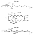
- Fig. 5B is a plan view illustrating the small block portion 28B
- Fig. 5A and Fig. 5C are opened out side views illustrating edge portions along the sipes 26A, 26B.
- an edge upper portion of the small block portion 28B along the sipe 26A slopes so as to gradually become lower on progression from the protrusion portions 30A toward the adjacent recessed portions 32A.
- an edge upper portion along the sipe 26B also slopes so as to gradually become lower on progression from the protrusion portions 30B toward the adjacent recessed portions 32B.
- a height difference G1 between the peak points 30BP and the trough points 32BP is preferably within a range from 0.1 mm to 1.0 mm, and more preferably within a range from 0.25 mm to 0.5 mm.
- a height difference G2 between the peak points 30AP and the trough points 32AP is also preferably within a range from 0.1 mm to 1.0 mm, and more preferably within a range from 0.25 mm to 0.5 mm.
- a height difference G3 between the peak points 30BP and the trough points 32AP is preferably within a range from 0.2 mm to 2.0 mm, and more preferably within a range from 0.5 mm to 1.0 mm.
- a height difference G4 between the peak points 30AP and the trough points 32BP is preferably within a range from 0.5 mm to 0.5 mm.
- the small block portion 28B and the small block portion 28C have the same shape as each other.
- portions corresponding to the protrusion portions 30A, 30B, the recessed portions 32A, 32B, the peak points 30AP, 30BP, and the trough points 32AP, 32BP of the small block portion 28B respectively configure protrusion portions 34A, 34B, recessed portions 36A, 36B, peak points 34AP, 34BP, and trough points 36AP, 36BP.
- the small block portion 28A has substantially the same shape as a portion of the small block portion 28B that is further toward the small block portion 28C side than toward the line M.
- An edge portion of the small block portion 28A running along the lug groove 22 has a straight line shape.
- portions corresponding to the protrusion portions 30B, the recessed portions 32B, the peak points 30BP, and the trough points 32BP of the small block portion 28B respectively configure protrusion portions 42, recessed portions 40, peak points 42P, and trough points 40P.
- the small block portion 28D has substantially the same shape as a portion of the small block portion 28B that is further toward the small block portion 28A side than toward the line M.
- An edge portion of the small block portion 28D running along the lug groove 22 has a straight line shape.
- portions corresponding to the protrusion portions 30A, the recessed portions 32A, the peak points 30AP, and the trough points 32AP of the small block portion 28B respectively configure protrusion portions 46, recessed portions 44, peak points 46P, and trough points 44P.
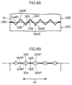
- Fig. 6A is a plan view illustrating portions of the small block portions 28B, 28C that are adjacent to each other on either side of the sipe 26B.
- Fig. 6B is a diagram illustrating the height of edge portions running along the sipe 26B, viewed from the tire circumferential direction. Steps in the tire width direction W are formed by the height difference between the protrusion portions 30B, the recessed portions 32B, the protrusion portions 34A, and the recessed portions 36A on either side of the sipe 26B.
- steps in the tire width direction W are formed between the small block portion 28A and the small block portion 28B disposed on either side of the sipe 26A, by the height difference between the protrusion portions 42, the recessed portions 40, the protrusion portions 30A, and the recessed portions 32A. Furthermore, steps in the tire width direction W are formed between the small block portion 28C and the small block portion 28D disposed on either side of the sipe 26C, by the height difference between the protrusion portions 34B, the recessed portions 36B, the protrusion portions 46, and the recessed portions 44.
- the protrusion portions disposed at the kick-off side of the sipe are higher than the protrusion portions disposed at the tread-in side. Note that the protrusion portions disposed at the kick-off side of the sipe are disposed inside a single small block portion at the tread-in end thereof, and the protrusion portions disposed at the tread-in side of the sipe are disposed inside a single small block portion at the kick-off end thereof.
- the tread-in ends of the small block portions 28A to 28D are higher in a cross-section around the tire circumferential direction of each block 24 along line A-A linking the peak points 42P, the trough points 32A, the peak points 30BP, the trough points 36AP, the peak points 34BP, and the trough points 44P.
- the kick-off ends of the small block portions 28A to 28D are higher in a cross-section of each block 24 along line D-D linking the trough points 40P, the peak points 30AP, the trough points 32BP, the peak points 34AP, the trough points 36BP, and the peak points 46P.
- Each block 24 of the pneumatic tire 10 includes the zigzag shaped sipes 26A to 26C extending along the tire width direction.
- the protrusion portions are higher than the recessed portions in the protrusion portions 42 and the recessed portions 40, the protrusion portions 30 and the recessed portions 32, the protrusion portions 34 and the recessed portions 36, and the protrusion portions 46 and the recessed portions 44 running along these sipes.
- the ground contact pressure of the edge portions of the protrusion portions that are relatively high accordingly increases due to the height difference between the protrusion portions and the recessed portions, thereby enabling the gripping performance to be improved.
- the protrusion portions and the recessed portions of the small block portions 28A to 28D respectively disposed on other either side of the sipes 26A to 26C are higher than the protrusion portions at the tread-in side. There is accordingly a height difference between the height of the protrusion portions disposed at the tread-in side, and the height of the protrusion portions of the block portions at the kick-off side on either side of the sipes 26A to 26C, with the protrusion portions at the kick-off side being higher.
- the ground contact pressure of the edge portions of the protrusion portions at the kick-off side on either side of the sipes 26A to 26C is thereby higher, thereby enabling the gripping performance to be further improved.
- the effect of the edge portions of the protrusion portions at the kick-off side catching enables the gripping performance on snowy roads to be improved.
- the protrusion portions at the kick-off side of the sipes are higher than the protrusion portions at the tread-in side; however, the height of the protrusion portions may be the same at the kick-off side as at the tread-in side of the sipes.
- three dimensional sipes that are zigzag shaped along the tire radial direction have been explained as an example of sipes; however, the sipes are not necessarily three dimensional sipes.
- Employing three dimensional sipes as in the present exemplary embodiment enables the rigidity of the small block portions 28 to be secured.
- sipes have been explained as an example of tire width direction grooves; however, the tire width direction grooves of the present invention may be fine grooves or lug grooves rather than sipes.
- the sipes extend parallel to the tire width direction; however, the sipes may extend at an angle to the tire width direction.
- the sipes 26 are formed as tire width direction grooves to the blocks; however, the tire width direction grooves of the present invention may be formed to ribs that are continuous land portions around the tire circumferential direction.
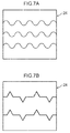
- the protrusion portions and the recessed portions are formed by the zigzag shaped sipes; however, the protrusion portions and the recessed portions of the present invention are not limited to being formed by zigzag shapes, and other shapes may be employed.
- wave shapes may be employed, or, as illustrated in Fig. 7B , shapes may be employed that include portions parallel to the tire width direction between the protrusion portions and the recessed portions.
- each small block portion 28B, 28C are different in height at both the tread-in end and the kick-off end sides; however, a configuration may be applied in which only the protrusion portions and the recessed portions at one side are different in height.
- the end side of each small block portion 28 further toward the block kick-off side than toward the line M may be configured in a flat shape that has entirely the same height.
- the heights of corresponding portions of the respective small block portions 28A to 28D are the same height; however, variation may be given to the height of each small block portion for small block portions that are adjacent to each other around the tire circumferential direction.
- high small block portions that have a higher overall block height and low block portions that have a lower overall block height may be disposed alternately to each other.
- a pneumatic tire of the present invention has been explained with a studless tire as an example; however, the present invention is not limited to a studless tire, and may also be applied to other pneumatic tires.
- a pneumatic tire including the tread pattern of the present exemplary embodiment illustrated in Fig. 1 was fitted to a vehicle, and the acceleration generated along the vehicle lateral direction was measured.
- the height difference between the peak points of the protrusion portions and the trough points of the recessed portions adjacent to each other along the sipes (hereafter simply referred to as "height difference") was varied, while other conditions were left the same.
- the tire size, test conditions, and method are given below. The test results are shown in Table 1.
Abstract
Description
- The present invention relates to a pneumatic tire including a land portion on a tread face.
- Generally in pneumatic tires, plural grooves are formed to a tread in order to exhibit an edge effect (see, for example, Patent Document 1). The edge effect is increased by forming a large number of the grooves, changing the direction of the grooves to form zigzag shapes, and lengthening the length of the grooves. However, increasing the density of grooves on the land portion of the tread lowers the rigidity of the land portion and results in an inward collapsing, such that it is difficult to effectively obtain gripping force.
- Patent Document 1 Japanese Patent Application Laid-Open (
JP-A) No. 2009-196442 - In consideration of the above circumstances, an object of the present invention is to provide a pneumatic tire with increased edge effect and improved gripping performance, even when the groove length is the same.
- A pneumatic tire according to a first aspect of the present invention is a pneumatic tire, including: a land portion that is formed at a tread and that is partitioned by a tire circumferential direction groove; plural tire width direction grooves that divide the land portion and that extend along a tire width direction; a block portion that is formed by partitioning by the tire width direction grooves; and, a protrusion portion that protrudes from the block portion, and a recessed portion that is recessed, with respect to an extension direction of the tire width direction grooves in plan view, which configure a portion of the block portion, wherein a block height of the protrusion portion is higher than a block height of the recessed portion formed along the same tire width direction groove.
- The pneumatic tire according to the first aspect of the present invention includes the land portion that is partitioned by the plural tire circumferential direction grooves on the tread. The land portion is divided by the plural tire width direction grooves extending along the tire width direction.
- Note that "land portion" is a portion of the tread that mainly forms a tread face, and refers at least to ribs or blocks that are partitioned by the tire circumferential direction grooves. The tire width direction grooves encompass lug grooves, these being grooves that do not close up during ground contact, and fine grooves, these being grooves that do close up during ground contact, such as what are referred to as sipes. Moreover, "divided" referred to herein encompasses cases that are not completely divided in plan view, and have a continuous portion, as well as cases that are completely divided in plan view. Furthermore, "extend along the tire width direction" refers to extension directions including a component in the tire width direction, as well as cases extending parallel to the tire width direction.
- In the pneumatic tire according to the first aspect, the block portion is formed by partitioning by the tire width direction grooves, and includes the protrusion portion that protrudes out from the block portion, and the recessed portion that is recessed, with respect to the extension direction of the tire width direction grooves in plan view. The block height of the protrusion portion is formed higher than the block height of the recessed portion formed by partitioning by the same tire width direction groove.
- Note that that protrusion portion is a portion of the land portion that protrudes out from the block portion, and the recessed portion is conversely a portion of the land portion that retreats into the block portion, with respect to the extension direction of the tire width direction grooves. In cases of a wave shape formed by contiguous protrusion portions and recessed portions, the protrusion portions and the recessed portions are divided with a center position of the amplitude of the waved shaped portion as a boundary.
- In the above configuration, there is a height difference between the protrusion portion and the recessed portion, such that an edge of the protrusion portion is relatively higher. This enables the ground contact pressure of the protrusion portion to be increased, and the gripping performance to be improved. Since the edge of the protrusion portion includes components in the tire circumferential direction and in the tire width direction, gripping performance can be improved not only when proceeding straight ahead, but also when turning.
- In a pneumatic tire according to a second aspect of the present invention, the block portion includes the protrusion portion at both sides in the tire circumferential direction, and the protrusion portion at a tread-in end side of the block portion has a higher block height than the protrusion portion at a kick-off end side of the block portion.
- In the pneumatic tire according to the second aspect, there is also a difference in height between the height of the protrusion portions disposed on both sides in the tire circumferential direction, and the protrusion portion at the tread-in end side is higher. The edge portion of the protrusion portion at the tread-in end side of the block portion is thereby higher, enabling gripping performance to be further improved.
- In a pneumatic tire according to a third aspect of the present invention, the tire width direction grooves are zigzag shaped with amplitude in the tire circumferential direction.
- Configuring the zigzag shaped tire width direction grooves in this manner enables repeatedly alternating protrusion portions and recessed portions to be formed inside a single block portion, and enables the gripping performance to be further improved by the height difference therebetween.
- In a pneumatic tire according to a fourth aspect of the present invention, the tire width direction grooves are sipes that close during ground contact.
- Making the height of the protrusion portion higher than the height of the recessed portion partitioned by the sipes in this manner enables gripping performance to be effectively improved using the sipes, which are relatively less liable to cause a reduction in the rigidity of the land portion, and which exhibit the edge effect.
- The present invention has the above configuration, thereby enabling the edge effect to be increased and gripping performance to be improved, even when the groove length of the land portion is the same.
-
-
Fig. 1 is an opened out view of a tread, illustrating a surface of a pneumatic tire according to an exemplary embodiment. -
Fig. 2 is an enlarged plan view of a block of a pneumatic tire according to the present exemplary embodiment. -
Fig. 3 is a perspective view of a block of a pneumatic tire according to the present exemplary embodiment. -
Fig. 4A is a cross-section along line A-A inFig. 2 . -
Fig. 4B is a cross-section along line B-B inFig. 2 . -
Fig. 5A is an opened out view of an edge portion of a small block portion. -
Fig. 5B is a plan view of a small block portion. -
Fig. 5C is an opened out view of an edge portion of a small block portion. -
Fig. 6A is a plan view of small block portions that are adjacent to each other on either side of a sipe. -
Fig. 6B is a drawing illustrating the height of edge portions of small block portions that are adjacent to each other on either side of a sipe. -
Fig. 7A is a plan view illustrating a block according to a modified example of a pneumatic tire of the present exemplary embodiment. -
Fig. 7B is a plan view illustrating a block according to a modified example of a pneumatic tire of the present exemplary embodiment. - Explanation follows regarding a
pneumatic tire 10 according to an exemplary embodiment of the present invention, with reference to the drawings. In the present exemplary embodiment, a studless tire that exhibits gripping force on snowy roads is explained as an example of thepneumatic tire 10. -
Fig. 1 is an opened-out view of atread 12 of thepneumatic tire 10. Thetread 12 of thepneumatic tire 10 of the present exemplary embodiment is shaped with left-right symmetry about a tire equatorial plane CL (a plane that divides thepneumatic tire 10 in two at the tire width direction center of the tread 12). Note that tire ground contact edges 12E of thetread 12 are the tire ground contact edges when thepneumatic tire 10 is fitted to a standard rim, as defined in the JATMAYEAR BOOK (2012 edition, Japan Automobile Tire Manufacturers Association standards), inflated to an internal pressure of 100% air pressure (maximum air pressure) corresponding to the maximum load capacity (load shown in bold in the internal pressure-load capacity correspondence table) for the applicable JATMAYEAR BOOK size/ply rating, and loaded to the maximum load capacity. In cases in which the location of use or manufacturing location applies TRA standards or ETRTO standards, then the respective standards are adhered to. - The rotation direction of the
pneumatic tire 10 is predetermined. In the drawings, the rotation direction is indicated by the arrow S, and the tire width direction that is orthogonal thereto is indicated by the arrow W, respectively. Note that the circumferential direction of thepneumatic tire 10 is the rotation direction and the opposite direction thereto. - The height of a land portion (block) corresponds to the distance from the tire axis, such that the further the distance from the tire axis the higher the height of the block, and the closer the distance from the tire axis the lower the height of the block
- Three tire
circumferential direction grooves tread 12 of thepneumatic tire 10 of the present exemplary embodiment. The tirecircumferential direction groove 20B is formed on the tire equatorial plane CL. The tirecircumferential direction grooves circumferential direction groove 20B.Lug grooves 22 running along the tire width direction are also formed to thetread 12.Plural lug grooves 22 are formed at specific intervals in the tire circumferential direction. - The
tread 12 is formed withplural blocks 24 that are partitioned by the tirecircumferential direction grooves 20A to 20C and thelug grooves 22.Sipes 26A to 26C extending along the tire width direction are formed to theblocks 24. Thesipes 26A to 26C are each formed in a zigzag shape with amplitude in the tire circumferential direction. The region of eachblock 24 is divided by thesipes 26A to 26C. Thesipes 26A to 26C each have a groove width of an amount so as to close up during ground contact, and are formed inside eachsingle block 24 at intervals along the tire circumferential direction. Theblock 24 is partitioned into foursmall block portions 28A to 28D by thesipes 26A to 26C. As illustrated inFig. 3 , thesipes 26A to 26C are also formed in zigzag shapes along the tire radial direction, and are what are referred to as three dimensional sipes (3D sipes). - As illustrated in
Fig. 2 , eachsmall block portion 28B includes protrusion portions 30 that each protrude out from thesmall block portion 28B with respect to the extension direction of thesipe 26A, namely, which each protrude in the tire circumferential direction when viewed in plan view. Thesmall block portion 28B also includes recessed portions 32 that are each recessed into thesmall block portion 28B with respect to the extension direction of thesipe 26A, namely, which are each recessed in the tire circumferential direction when viewed in plan view. The protrusion portions 30 and the recessed portions 32 at a tread-in end side of thesmall block portion 28B respectively configureprotrusion portions 30B and recessedportions 32B, and the protrusion portions 30 and the recessed portions 32 at a kick-off end side respectively configureprotrusion portions 30A and recessedportions 32A. Theprotrusion portions portions Fig. 2 , supposing that there are lines M that are each in a tire circumferential direction center position with respect to an amplitude A of thesipes small block portion 28B further than the lines M configure the protrusion portions 30, and portions entering (retreating to) thesmall block portion 28B side configure the recessed portions 32. Similar applies to the protrusion portions and recessed portions of the small block portions described below when viewed in plan view. Peak points of theprotrusion portions portions - The block height inside the
small block portion 28B is not uniform, and has a difference in height in which the height gradually changes. The block height inside thesmall block portion 28B is highest at the peak points 30BP, and lowest at the trough points 32AP. As illustrated inFig. 4A , the height slopes from each peak point 30BP across to the trough point 32AP that faces this peak point 30BP in the tire circumferential direction, so as to gradually become lower on progression from the peak point 30BP toward the trough point 32AP. As illustrated inFig. 4B , the height also slopes from each peak point 30AP across to the trough point 32BP that faces this peak point 30AP in the tire circumferential direction, so as to gradually become lower on progression from the peak point 30AP toward the trough point 32BP. As illustrated inFig. 6B , the height of peak points 34AP formed along thesipe 26B is lower than that of the peak points 30BP, and the height of the trough points 32AP is lower than the trough points BP. The height of the peak points 30AP is higher than the trough points BP. -
Fig. 5B is a plan view illustrating thesmall block portion 28B, andFig. 5A and Fig. 5C are opened out side views illustrating edge portions along thesipes Fig. 5A , an edge upper portion of thesmall block portion 28B along thesipe 26A slopes so as to gradually become lower on progression from theprotrusion portions 30A toward the adjacent recessedportions 32A. As illustrated inFig. 5C , an edge upper portion along thesipe 26B also slopes so as to gradually become lower on progression from theprotrusion portions 30B toward the adjacent recessedportions 32B. - A height difference G1 between the peak points 30BP and the trough points 32BP is preferably within a range from 0.1 mm to 1.0 mm, and more preferably within a range from 0.25 mm to 0.5 mm. A height difference G2 between the peak points 30AP and the trough points 32AP is also preferably within a range from 0.1 mm to 1.0 mm, and more preferably within a range from 0.25 mm to 0.5 mm. A height difference G3 between the peak points 30BP and the trough points 32AP (see
Fig. 4A ) is preferably within a range from 0.2 mm to 2.0 mm, and more preferably within a range from 0.5 mm to 1.0 mm. A height difference G4 between the peak points 30AP and the trough points 32BP (seeFig. 4B ) is preferably within a range from 0.5 mm to 0.5 mm. - The
small block portion 28B and thesmall block portion 28C have the same shape as each other. In thesmall block portion 28C, portions corresponding to theprotrusion portions portions small block portion 28B respectively configureprotrusion portions portions - The
small block portion 28A has substantially the same shape as a portion of thesmall block portion 28B that is further toward thesmall block portion 28C side than toward the line M. An edge portion of thesmall block portion 28A running along thelug groove 22 has a straight line shape. In thesmall block portion 28A, portions corresponding to theprotrusion portions 30B, the recessedportions 32B, the peak points 30BP, and the trough points 32BP of thesmall block portion 28B respectively configureprotrusion portions 42, recessedportions 40,peak points 42P, andtrough points 40P. - The
small block portion 28D has substantially the same shape as a portion of thesmall block portion 28B that is further toward thesmall block portion 28A side than toward the line M. An edge portion of thesmall block portion 28D running along thelug groove 22 has a straight line shape. In thesmall block portion 28D, portions corresponding to theprotrusion portions 30A, the recessedportions 32A, the peak points 30AP, and the trough points 32AP of thesmall block portion 28B respectively configureprotrusion portions 46, recessedportions 44, peak points 46P, andtrough points 44P. -
Fig. 6A is a plan view illustrating portions of thesmall block portions sipe 26B.Fig. 6B is a diagram illustrating the height of edge portions running along thesipe 26B, viewed from the tire circumferential direction. Steps in the tire width direction W are formed by the height difference between theprotrusion portions 30B, the recessedportions 32B, theprotrusion portions 34A, and the recessedportions 36A on either side of thesipe 26B. Similarly, steps in the tire width direction W are formed between thesmall block portion 28A and thesmall block portion 28B disposed on either side of thesipe 26A, by the height difference between theprotrusion portions 42, the recessedportions 40, theprotrusion portions 30A, and the recessedportions 32A. Furthermore, steps in the tire width direction W are formed between thesmall block portion 28C and thesmall block portion 28D disposed on either side of thesipe 26C, by the height difference between theprotrusion portions 34B, the recessedportions 36B, theprotrusion portions 46, and the recessedportions 44. - In each of the small block portions that are adjacent to each other on either side of the
sipes 26A to 26C, the protrusion portions disposed at the kick-off side of the sipe are higher than the protrusion portions disposed at the tread-in side. Note that the protrusion portions disposed at the kick-off side of the sipe are disposed inside a single small block portion at the tread-in end thereof, and the protrusion portions disposed at the tread-in side of the sipe are disposed inside a single small block portion at the kick-off end thereof. - As illustrated in
Fig. 4A , the tread-in ends of thesmall block portions 28A to 28D are higher in a cross-section around the tire circumferential direction of eachblock 24 along line A-A linking the peak points 42P, the trough points 32A, the peak points 30BP, the trough points 36AP, the peak points 34BP, and the trough points 44P. As illustrated inFig. 4B , the kick-off ends of thesmall block portions 28A to 28D are higher in a cross-section of eachblock 24 along line D-D linking the trough points 40P, the peak points 30AP, the trough points 32BP, the peak points 34AP, the trough points 36BP, and the peak points 46P. - Explanation follows regarding effects of the
pneumatic tire 10 of the present exemplary embodiment. - Each
block 24 of thepneumatic tire 10 includes the zigzag shapedsipes 26A to 26C extending along the tire width direction. The protrusion portions are higher than the recessed portions in theprotrusion portions 42 and the recessedportions 40, the protrusion portions 30 and the recessed portions 32, the protrusion portions 34 and the recessed portions 36, and theprotrusion portions 46 and the recessedportions 44 running along these sipes. The ground contact pressure of the edge portions of the protrusion portions that are relatively high accordingly increases due to the height difference between the protrusion portions and the recessed portions, thereby enabling the gripping performance to be improved. - In the protrusion portions and the recessed portions of the
small block portions 28A to 28D respectively disposed on other either side of thesipes 26A to 26C, the protrusion portions at the kick-off side of the sipes are higher than the protrusion portions at the tread-in side. There is accordingly a height difference between the height of the protrusion portions disposed at the tread-in side, and the height of the protrusion portions of the block portions at the kick-off side on either side of thesipes 26A to 26C, with the protrusion portions at the kick-off side being higher. The ground contact pressure of the edge portions of the protrusion portions at the kick-off side on either side of thesipes 26A to 26C is thereby higher, thereby enabling the gripping performance to be further improved. The effect of the edge portions of the protrusion portions at the kick-off side catching enables the gripping performance on snowy roads to be improved. - Note that, as previously described, at the protrusion portions and the recessed portions of the
small block portions 28A to 28D that are respectively disposed on either side of thesipes 26A to 26C in the present exemplary embodiment, the protrusion portions at the kick-off side of the sipes are higher than the protrusion portions at the tread-in side; however, the height of the protrusion portions may be the same at the kick-off side as at the tread-in side of the sipes. - In the present exemplary embodiment, three dimensional sipes that are zigzag shaped along the tire radial direction have been explained as an example of sipes; however, the sipes are not necessarily three dimensional sipes. Employing three dimensional sipes as in the present exemplary embodiment enables the rigidity of the small block portions 28 to be secured.
- In the present exemplary embodiment, sipes have been explained as an example of tire width direction grooves; however, the tire width direction grooves of the present invention may be fine grooves or lug grooves rather than sipes. In the present exemplary embodiment, an example has been explained in which the sipes extend parallel to the tire width direction; however, the sipes may extend at an angle to the tire width direction.
- In the present exemplary embodiment, an example has been explained in which the sipes 26 are formed as tire width direction grooves to the blocks; however, the tire width direction grooves of the present invention may be formed to ribs that are continuous land portions around the tire circumferential direction.
- In the present exemplary embodiment, an example has been explained in which the protrusion portions and the recessed portions are formed by the zigzag shaped sipes; however, the protrusion portions and the recessed portions of the present invention are not limited to being formed by zigzag shapes, and other shapes may be employed. For example, as illustrated in
Fig. 7A , wave shapes may be employed, or, as illustrated inFig. 7B , shapes may be employed that include portions parallel to the tire width direction between the protrusion portions and the recessed portions. - In the present exemplary embodiment, an example has been explained in which the protrusion portions and the recessed portions of the
small block portions - In the present exemplary embodiment, the heights of corresponding portions of the respective
small block portions 28A to 28D are the same height; however, variation may be given to the height of each small block portion for small block portions that are adjacent to each other around the tire circumferential direction. For example, in the small block portions 28 that are adjacent to each other around the tire circumferential direction, high small block portions that have a higher overall block height and low block portions that have a lower overall block height may be disposed alternately to each other. By making such variations, the height difference between adjacent small block portions increases, enabling the ground contact pressure to be further increased. - Note that, in the present exemplary embodiment, a pneumatic tire with a predetermined rotation direction has been explained; however, the present invention may be applied to a pneumatic tire without a prescribed rotation direction.
- In the present exemplary embodiment, a pneumatic tire of the present invention has been explained with a studless tire as an example; however, the present invention is not limited to a studless tire, and may also be applied to other pneumatic tires.
- In order to confirm the advantageous effects of the present invention, a pneumatic tire including the tread pattern of the present exemplary embodiment illustrated in
Fig. 1 was fitted to a vehicle, and the acceleration generated along the vehicle lateral direction was measured. The height difference between the peak points of the protrusion portions and the trough points of the recessed portions adjacent to each other along the sipes (hereafter simply referred to as "height difference") was varied, while other conditions were left the same. The tire size, test conditions, and method are given below. The test results are shown in Table 1. -
- Tire size: 225/45R17
- Rim: 7.5J
- Internal pressure:230/230 kPa
- Load: Weight of driver + 60 kg (588N)
- Speed: 45 km/h, constant
- Steering angle: 135°/0.5 sec
- Test method: The maximum acceleration was averaged over 20 cycles and indexed. In the index, higher values indicate larger gripping force.
- As shown in Table 1, it was confirmed that a superior gripping force can be obtained when the height difference is within a range from 0.15 mm to 1.0 mm, compared to cases in which there is no height difference.
| Height difference (mm) | 0 | 0.15 | 0.25 | 0.28 | 0.50 | 1.00 |
| Average acceleration | 3.7 | 3.9 | 4.1 | 4.3 | 4.2 | 3.8 |
Claims (4)
- A pneumatic tire, comprising:a land portion that is formed at a tread and that is partitioned by a tire circumferential direction groove;a plurality of tire width direction grooves that divide the land portion and that extend along a tire width direction;a block portion that is formed by partitioning by the tire width direction grooves; and,a protrusion portion that protrudes from the block portion, and a recessed portion that is recessed, with respect to an extension direction of the tire width direction grooves in plan view, which configure a portion of the block portion,wherein a block height of the protrusion portion is higher than a block height of the recessed portion formed along the same tire width direction groove.
- The pneumatic tire of claim 1, wherein:the block portion includes the protrusion portion at both sides in the tire circumferential direction; andthe protrusion portion at a tread-in end side of the block portion has a higher block height than the protrusion portion at a kick-off end side of the block portion.
- The pneumatic tire of claim 1 or claim 2, wherein the tire width direction grooves are zigzag shaped with amplitude in the tire circumferential direction.
- The pneumatic tire of any one of claim 1 to claim 3, wherein the tire width direction grooves are sipes that close during ground contact.
Applications Claiming Priority (2)
| Application Number | Priority Date | Filing Date | Title |
|---|---|---|---|
| JP2013155049A JP5925735B2 (en) | 2013-07-25 | 2013-07-25 | Pneumatic tire |
| PCT/JP2014/066719 WO2015012048A1 (en) | 2013-07-25 | 2014-06-24 | Pneumatic tire |
Publications (3)
| Publication Number | Publication Date |
|---|---|
| EP3025876A1 true EP3025876A1 (en) | 2016-06-01 |
| EP3025876A4 EP3025876A4 (en) | 2016-08-03 |
| EP3025876B1 EP3025876B1 (en) | 2018-12-12 |
Family
ID=52393100
Family Applications (1)
| Application Number | Title | Priority Date | Filing Date |
|---|---|---|---|
| EP14828927.5A Active EP3025876B1 (en) | 2013-07-25 | 2014-06-24 | Pneumatic tire |
Country Status (4)
| Country | Link |
|---|---|
| EP (1) | EP3025876B1 (en) |
| JP (1) | JP5925735B2 (en) |
| CN (1) | CN105408133B (en) |
| WO (1) | WO2015012048A1 (en) |
Families Citing this family (2)
| Publication number | Priority date | Publication date | Assignee | Title |
|---|---|---|---|---|
| WO2018044305A1 (en) * | 2016-08-31 | 2018-03-08 | Compagnie Generale Des Etablissements Michelin | Tire tread |
| KR101849232B1 (en) * | 2016-09-07 | 2018-04-16 | 넥센타이어 주식회사 | Pneumatic snow tire |
Family Cites Families (7)
| Publication number | Priority date | Publication date | Assignee | Title |
|---|---|---|---|---|
| JPH071919A (en) * | 1993-06-15 | 1995-01-06 | Ohtsu Tire & Rubber Co Ltd :The | Tire with rugged tread surface |
| JP3656731B2 (en) * | 2000-08-24 | 2005-06-08 | 横浜ゴム株式会社 | Pneumatic tire |
| JP2003191716A (en) * | 2001-12-27 | 2003-07-09 | Bridgestone Corp | Pneumatic tire |
| JP2006131021A (en) * | 2004-11-04 | 2006-05-25 | Bridgestone Corp | Pneumatic tire |
| JP2007022242A (en) * | 2005-07-14 | 2007-02-01 | Yokohama Rubber Co Ltd:The | Pneumatic tire |
| JP4892889B2 (en) * | 2005-08-18 | 2012-03-07 | 横浜ゴム株式会社 | Pneumatic tire |
| JP2009196442A (en) | 2008-02-20 | 2009-09-03 | Bridgestone Corp | Pneumatic tire |
-
2013
- 2013-07-25 JP JP2013155049A patent/JP5925735B2/en active Active
-
2014
- 2014-06-24 CN CN201480041435.9A patent/CN105408133B/en active Active
- 2014-06-24 EP EP14828927.5A patent/EP3025876B1/en active Active
- 2014-06-24 WO PCT/JP2014/066719 patent/WO2015012048A1/en active Application Filing
Also Published As
| Publication number | Publication date |
|---|---|
| JP2015024732A (en) | 2015-02-05 |
| EP3025876B1 (en) | 2018-12-12 |
| EP3025876A4 (en) | 2016-08-03 |
| CN105408133B (en) | 2017-10-03 |
| CN105408133A (en) | 2016-03-16 |
| JP5925735B2 (en) | 2016-05-25 |
| WO2015012048A1 (en) | 2015-01-29 |
Similar Documents
| Publication | Publication Date | Title |
|---|---|---|
| EP2314464B1 (en) | Pneumatic tire | |
| EP3153334B1 (en) | Tire | |
| EP2163405B1 (en) | Pneumatic tire | |
| JP5971280B2 (en) | Pneumatic tire | |
| CN107539030B (en) | Tyre for vehicle wheels | |
| EP3421263A1 (en) | Tire | |
| CN109070655B (en) | Pneumatic tire | |
| EP3025877B1 (en) | Pneumatic tire | |
| US11027579B2 (en) | Pneumatic tire | |
| EP3130480B1 (en) | Pneumatic tire | |
| US11407255B2 (en) | Pneumatic tire | |
| EP3115229B1 (en) | Heavy duty pneumatic tire | |
| EP2540526A1 (en) | Pneumatic tire | |
| JP2018001941A (en) | Pneumatic tire | |
| EP3015289A1 (en) | Pneumatic tire | |
| JP2018134992A (en) | Pneumatic tire | |
| EP3025876B1 (en) | Pneumatic tire | |
| JP6416024B2 (en) | Pneumatic tire | |
| JP2021138346A (en) | tire | |
| CN114746290B (en) | Pneumatic tire | |
| JP7420541B2 (en) | pneumatic tires | |
| EP2987654B1 (en) | Pneumatic tire | |
| WO2023074032A1 (en) | Tire | |
| JP2024008620A (en) | tire | |
| JP2015020721A (en) | Pneumatic tire |
Legal Events
| Date | Code | Title | Description |
|---|---|---|---|
| PUAI | Public reference made under article 153(3) epc to a published international application that has entered the european phase |
Free format text: ORIGINAL CODE: 0009012 |
|
| 17P | Request for examination filed |
Effective date: 20160203 |
|
| AK | Designated contracting states |
Kind code of ref document: A1 Designated state(s): AL AT BE BG CH CY CZ DE DK EE ES FI FR GB GR HR HU IE IS IT LI LT LU LV MC MK MT NL NO PL PT RO RS SE SI SK SM TR |
|
| AX | Request for extension of the european patent |
Extension state: BA ME |
|
| A4 | Supplementary search report drawn up and despatched |
Effective date: 20160701 |
|
| RIC1 | Information provided on ipc code assigned before grant |
Ipc: B60C 11/12 20060101AFI20160627BHEP Ipc: B60C 11/11 20060101ALI20160627BHEP Ipc: B60C 11/04 20060101ALI20160627BHEP Ipc: B60C 11/03 20060101ALI20160627BHEP Ipc: B60C 11/13 20060101ALI20160627BHEP |
|
| DAX | Request for extension of the european patent (deleted) | ||
| STAA | Information on the status of an ep patent application or granted ep patent |
Free format text: STATUS: EXAMINATION IS IN PROGRESS |
|
| 17Q | First examination report despatched |
Effective date: 20171124 |
|
| GRAP | Despatch of communication of intention to grant a patent |
Free format text: ORIGINAL CODE: EPIDOSNIGR1 |
|
| STAA | Information on the status of an ep patent application or granted ep patent |
Free format text: STATUS: GRANT OF PATENT IS INTENDED |
|
| INTG | Intention to grant announced |
Effective date: 20180709 |
|
| GRAS | Grant fee paid |
Free format text: ORIGINAL CODE: EPIDOSNIGR3 |
|
| GRAA | (expected) grant |
Free format text: ORIGINAL CODE: 0009210 |
|
| STAA | Information on the status of an ep patent application or granted ep patent |
Free format text: STATUS: THE PATENT HAS BEEN GRANTED |
|
| AK | Designated contracting states |
Kind code of ref document: B1 Designated state(s): AL AT BE BG CH CY CZ DE DK EE ES FI FR GB GR HR HU IE IS IT LI LT LU LV MC MK MT NL NO PL PT RO RS SE SI SK SM TR |
|
| REG | Reference to a national code |
Ref country code: GB Ref legal event code: FG4D |
|
| REG | Reference to a national code |
Ref country code: CH Ref legal event code: EP |
|
| REG | Reference to a national code |
Ref country code: AT Ref legal event code: REF Ref document number: 1075447 Country of ref document: AT Kind code of ref document: T Effective date: 20181215 |
|
| REG | Reference to a national code |
Ref country code: DE Ref legal event code: R096 Ref document number: 602014037953 Country of ref document: DE |
|
| REG | Reference to a national code |
Ref country code: IE Ref legal event code: FG4D |
|
| REG | Reference to a national code |
Ref country code: NL Ref legal event code: MP Effective date: 20181212 |
|
| REG | Reference to a national code |
Ref country code: LT Ref legal event code: MG4D |
|
| PG25 | Lapsed in a contracting state [announced via postgrant information from national office to epo] |
Ref country code: BG Free format text: LAPSE BECAUSE OF FAILURE TO SUBMIT A TRANSLATION OF THE DESCRIPTION OR TO PAY THE FEE WITHIN THE PRESCRIBED TIME-LIMIT Effective date: 20190312 Ref country code: FI Free format text: LAPSE BECAUSE OF FAILURE TO SUBMIT A TRANSLATION OF THE DESCRIPTION OR TO PAY THE FEE WITHIN THE PRESCRIBED TIME-LIMIT Effective date: 20181212 Ref country code: ES Free format text: LAPSE BECAUSE OF FAILURE TO SUBMIT A TRANSLATION OF THE DESCRIPTION OR TO PAY THE FEE WITHIN THE PRESCRIBED TIME-LIMIT Effective date: 20181212 Ref country code: LV Free format text: LAPSE BECAUSE OF FAILURE TO SUBMIT A TRANSLATION OF THE DESCRIPTION OR TO PAY THE FEE WITHIN THE PRESCRIBED TIME-LIMIT Effective date: 20181212 Ref country code: HR Free format text: LAPSE BECAUSE OF FAILURE TO SUBMIT A TRANSLATION OF THE DESCRIPTION OR TO PAY THE FEE WITHIN THE PRESCRIBED TIME-LIMIT Effective date: 20181212 Ref country code: NO Free format text: LAPSE BECAUSE OF FAILURE TO SUBMIT A TRANSLATION OF THE DESCRIPTION OR TO PAY THE FEE WITHIN THE PRESCRIBED TIME-LIMIT Effective date: 20190312 Ref country code: LT Free format text: LAPSE BECAUSE OF FAILURE TO SUBMIT A TRANSLATION OF THE DESCRIPTION OR TO PAY THE FEE WITHIN THE PRESCRIBED TIME-LIMIT Effective date: 20181212 |
|
| REG | Reference to a national code |
Ref country code: AT Ref legal event code: MK05 Ref document number: 1075447 Country of ref document: AT Kind code of ref document: T Effective date: 20181212 |
|
| PG25 | Lapsed in a contracting state [announced via postgrant information from national office to epo] |
Ref country code: RS Free format text: LAPSE BECAUSE OF FAILURE TO SUBMIT A TRANSLATION OF THE DESCRIPTION OR TO PAY THE FEE WITHIN THE PRESCRIBED TIME-LIMIT Effective date: 20181212 Ref country code: SE Free format text: LAPSE BECAUSE OF FAILURE TO SUBMIT A TRANSLATION OF THE DESCRIPTION OR TO PAY THE FEE WITHIN THE PRESCRIBED TIME-LIMIT Effective date: 20181212 Ref country code: GR Free format text: LAPSE BECAUSE OF FAILURE TO SUBMIT A TRANSLATION OF THE DESCRIPTION OR TO PAY THE FEE WITHIN THE PRESCRIBED TIME-LIMIT Effective date: 20190313 Ref country code: AL Free format text: LAPSE BECAUSE OF FAILURE TO SUBMIT A TRANSLATION OF THE DESCRIPTION OR TO PAY THE FEE WITHIN THE PRESCRIBED TIME-LIMIT Effective date: 20181212 |
|
| PG25 | Lapsed in a contracting state [announced via postgrant information from national office to epo] |
Ref country code: NL Free format text: LAPSE BECAUSE OF FAILURE TO SUBMIT A TRANSLATION OF THE DESCRIPTION OR TO PAY THE FEE WITHIN THE PRESCRIBED TIME-LIMIT Effective date: 20181212 |
|
| PG25 | Lapsed in a contracting state [announced via postgrant information from national office to epo] |
Ref country code: IT Free format text: LAPSE BECAUSE OF FAILURE TO SUBMIT A TRANSLATION OF THE DESCRIPTION OR TO PAY THE FEE WITHIN THE PRESCRIBED TIME-LIMIT Effective date: 20181212 Ref country code: PL Free format text: LAPSE BECAUSE OF FAILURE TO SUBMIT A TRANSLATION OF THE DESCRIPTION OR TO PAY THE FEE WITHIN THE PRESCRIBED TIME-LIMIT Effective date: 20181212 Ref country code: PT Free format text: LAPSE BECAUSE OF FAILURE TO SUBMIT A TRANSLATION OF THE DESCRIPTION OR TO PAY THE FEE WITHIN THE PRESCRIBED TIME-LIMIT Effective date: 20190412 Ref country code: CZ Free format text: LAPSE BECAUSE OF FAILURE TO SUBMIT A TRANSLATION OF THE DESCRIPTION OR TO PAY THE FEE WITHIN THE PRESCRIBED TIME-LIMIT Effective date: 20181212 |
|
| PG25 | Lapsed in a contracting state [announced via postgrant information from national office to epo] |
Ref country code: SM Free format text: LAPSE BECAUSE OF FAILURE TO SUBMIT A TRANSLATION OF THE DESCRIPTION OR TO PAY THE FEE WITHIN THE PRESCRIBED TIME-LIMIT Effective date: 20181212 Ref country code: EE Free format text: LAPSE BECAUSE OF FAILURE TO SUBMIT A TRANSLATION OF THE DESCRIPTION OR TO PAY THE FEE WITHIN THE PRESCRIBED TIME-LIMIT Effective date: 20181212 Ref country code: SK Free format text: LAPSE BECAUSE OF FAILURE TO SUBMIT A TRANSLATION OF THE DESCRIPTION OR TO PAY THE FEE WITHIN THE PRESCRIBED TIME-LIMIT Effective date: 20181212 Ref country code: IS Free format text: LAPSE BECAUSE OF FAILURE TO SUBMIT A TRANSLATION OF THE DESCRIPTION OR TO PAY THE FEE WITHIN THE PRESCRIBED TIME-LIMIT Effective date: 20190412 Ref country code: RO Free format text: LAPSE BECAUSE OF FAILURE TO SUBMIT A TRANSLATION OF THE DESCRIPTION OR TO PAY THE FEE WITHIN THE PRESCRIBED TIME-LIMIT Effective date: 20181212 |
|
| REG | Reference to a national code |
Ref country code: DE Ref legal event code: R097 Ref document number: 602014037953 Country of ref document: DE |
|
| PLBE | No opposition filed within time limit |
Free format text: ORIGINAL CODE: 0009261 |
|
| STAA | Information on the status of an ep patent application or granted ep patent |
Free format text: STATUS: NO OPPOSITION FILED WITHIN TIME LIMIT |
|
| PG25 | Lapsed in a contracting state [announced via postgrant information from national office to epo] |
Ref country code: DK Free format text: LAPSE BECAUSE OF FAILURE TO SUBMIT A TRANSLATION OF THE DESCRIPTION OR TO PAY THE FEE WITHIN THE PRESCRIBED TIME-LIMIT Effective date: 20181212 Ref country code: AT Free format text: LAPSE BECAUSE OF FAILURE TO SUBMIT A TRANSLATION OF THE DESCRIPTION OR TO PAY THE FEE WITHIN THE PRESCRIBED TIME-LIMIT Effective date: 20181212 Ref country code: SI Free format text: LAPSE BECAUSE OF FAILURE TO SUBMIT A TRANSLATION OF THE DESCRIPTION OR TO PAY THE FEE WITHIN THE PRESCRIBED TIME-LIMIT Effective date: 20181212 |
|
| 26N | No opposition filed |
Effective date: 20190913 |
|
| PG25 | Lapsed in a contracting state [announced via postgrant information from national office to epo] |
Ref country code: MC Free format text: LAPSE BECAUSE OF FAILURE TO SUBMIT A TRANSLATION OF THE DESCRIPTION OR TO PAY THE FEE WITHIN THE PRESCRIBED TIME-LIMIT Effective date: 20181212 |
|
| REG | Reference to a national code |
Ref country code: CH Ref legal event code: PL |
|
| GBPC | Gb: european patent ceased through non-payment of renewal fee |
Effective date: 20190624 |
|
| REG | Reference to a national code |
Ref country code: BE Ref legal event code: MM Effective date: 20190630 |
|
| PG25 | Lapsed in a contracting state [announced via postgrant information from national office to epo] |
Ref country code: TR Free format text: LAPSE BECAUSE OF FAILURE TO SUBMIT A TRANSLATION OF THE DESCRIPTION OR TO PAY THE FEE WITHIN THE PRESCRIBED TIME-LIMIT Effective date: 20181212 |
|
| PG25 | Lapsed in a contracting state [announced via postgrant information from national office to epo] |
Ref country code: GB Free format text: LAPSE BECAUSE OF NON-PAYMENT OF DUE FEES Effective date: 20190624 Ref country code: IE Free format text: LAPSE BECAUSE OF NON-PAYMENT OF DUE FEES Effective date: 20190624 |
|
| PG25 | Lapsed in a contracting state [announced via postgrant information from national office to epo] |
Ref country code: CH Free format text: LAPSE BECAUSE OF NON-PAYMENT OF DUE FEES Effective date: 20190630 Ref country code: BE Free format text: LAPSE BECAUSE OF NON-PAYMENT OF DUE FEES Effective date: 20190630 Ref country code: LI Free format text: LAPSE BECAUSE OF NON-PAYMENT OF DUE FEES Effective date: 20190630 Ref country code: LU Free format text: LAPSE BECAUSE OF NON-PAYMENT OF DUE FEES Effective date: 20190624 |
|
| PG25 | Lapsed in a contracting state [announced via postgrant information from national office to epo] |
Ref country code: CY Free format text: LAPSE BECAUSE OF FAILURE TO SUBMIT A TRANSLATION OF THE DESCRIPTION OR TO PAY THE FEE WITHIN THE PRESCRIBED TIME-LIMIT Effective date: 20181212 |
|
| PG25 | Lapsed in a contracting state [announced via postgrant information from national office to epo] |
Ref country code: HU Free format text: LAPSE BECAUSE OF FAILURE TO SUBMIT A TRANSLATION OF THE DESCRIPTION OR TO PAY THE FEE WITHIN THE PRESCRIBED TIME-LIMIT; INVALID AB INITIO Effective date: 20140624 Ref country code: MT Free format text: LAPSE BECAUSE OF FAILURE TO SUBMIT A TRANSLATION OF THE DESCRIPTION OR TO PAY THE FEE WITHIN THE PRESCRIBED TIME-LIMIT Effective date: 20181212 |
|
| PG25 | Lapsed in a contracting state [announced via postgrant information from national office to epo] |
Ref country code: MK Free format text: LAPSE BECAUSE OF FAILURE TO SUBMIT A TRANSLATION OF THE DESCRIPTION OR TO PAY THE FEE WITHIN THE PRESCRIBED TIME-LIMIT Effective date: 20181212 |
|
| PGFP | Annual fee paid to national office [announced via postgrant information from national office to epo] |
Ref country code: DE Payment date: 20220620 Year of fee payment: 9 |
|
| PGFP | Annual fee paid to national office [announced via postgrant information from national office to epo] |
Ref country code: FR Payment date: 20220628 Year of fee payment: 9 |
|
| P01 | Opt-out of the competence of the unified patent court (upc) registered |
Effective date: 20230531 |
|
| REG | Reference to a national code |
Ref country code: DE Ref legal event code: R119 Ref document number: 602014037953 Country of ref document: DE |
|
| PG25 | Lapsed in a contracting state [announced via postgrant information from national office to epo] |
Ref country code: DE Free format text: LAPSE BECAUSE OF NON-PAYMENT OF DUE FEES Effective date: 20240103 |