EP3025853A1 - Composite laminate including interlayers with through-plane regions fused to fiber beds - Google Patents
Composite laminate including interlayers with through-plane regions fused to fiber beds Download PDFInfo
- Publication number
- EP3025853A1 EP3025853A1 EP15192574.0A EP15192574A EP3025853A1 EP 3025853 A1 EP3025853 A1 EP 3025853A1 EP 15192574 A EP15192574 A EP 15192574A EP 3025853 A1 EP3025853 A1 EP 3025853A1
- Authority
- EP
- European Patent Office
- Prior art keywords
- fiber
- beds
- interlayer
- fused
- fiber beds
- Prior art date
- Legal status (The legal status is an assumption and is not a legal conclusion. Google has not performed a legal analysis and makes no representation as to the accuracy of the status listed.)
- Ceased
Links
Images


Classifications
-
- B—PERFORMING OPERATIONS; TRANSPORTING
- B32—LAYERED PRODUCTS
- B32B—LAYERED PRODUCTS, i.e. PRODUCTS BUILT-UP OF STRATA OF FLAT OR NON-FLAT, e.g. CELLULAR OR HONEYCOMB, FORM
- B32B5/00—Layered products characterised by the non- homogeneity or physical structure, i.e. comprising a fibrous, filamentary, particulate or foam layer; Layered products characterised by having a layer differing constitutionally or physically in different parts
- B32B5/02—Layered products characterised by the non- homogeneity or physical structure, i.e. comprising a fibrous, filamentary, particulate or foam layer; Layered products characterised by having a layer differing constitutionally or physically in different parts characterised by structural features of a fibrous or filamentary layer
-
- B—PERFORMING OPERATIONS; TRANSPORTING
- B32—LAYERED PRODUCTS
- B32B—LAYERED PRODUCTS, i.e. PRODUCTS BUILT-UP OF STRATA OF FLAT OR NON-FLAT, e.g. CELLULAR OR HONEYCOMB, FORM
- B32B5/00—Layered products characterised by the non- homogeneity or physical structure, i.e. comprising a fibrous, filamentary, particulate or foam layer; Layered products characterised by having a layer differing constitutionally or physically in different parts
- B32B5/14—Layered products characterised by the non- homogeneity or physical structure, i.e. comprising a fibrous, filamentary, particulate or foam layer; Layered products characterised by having a layer differing constitutionally or physically in different parts characterised by a layer differing constitutionally or physically in different parts, e.g. denser near its faces
- B32B5/142—Variation across the area of the layer
-
- B—PERFORMING OPERATIONS; TRANSPORTING
- B32—LAYERED PRODUCTS
- B32B—LAYERED PRODUCTS, i.e. PRODUCTS BUILT-UP OF STRATA OF FLAT OR NON-FLAT, e.g. CELLULAR OR HONEYCOMB, FORM
- B32B1/00—Layered products having a non-planar shape
-
- B—PERFORMING OPERATIONS; TRANSPORTING
- B32—LAYERED PRODUCTS
- B32B—LAYERED PRODUCTS, i.e. PRODUCTS BUILT-UP OF STRATA OF FLAT OR NON-FLAT, e.g. CELLULAR OR HONEYCOMB, FORM
- B32B27/00—Layered products comprising a layer of synthetic resin
-
- B—PERFORMING OPERATIONS; TRANSPORTING
- B32—LAYERED PRODUCTS
- B32B—LAYERED PRODUCTS, i.e. PRODUCTS BUILT-UP OF STRATA OF FLAT OR NON-FLAT, e.g. CELLULAR OR HONEYCOMB, FORM
- B32B27/00—Layered products comprising a layer of synthetic resin
- B32B27/06—Layered products comprising a layer of synthetic resin as the main or only constituent of a layer, which is next to another layer of the same or of a different material
- B32B27/08—Layered products comprising a layer of synthetic resin as the main or only constituent of a layer, which is next to another layer of the same or of a different material of synthetic resin
-
- B—PERFORMING OPERATIONS; TRANSPORTING
- B32—LAYERED PRODUCTS
- B32B—LAYERED PRODUCTS, i.e. PRODUCTS BUILT-UP OF STRATA OF FLAT OR NON-FLAT, e.g. CELLULAR OR HONEYCOMB, FORM
- B32B27/00—Layered products comprising a layer of synthetic resin
- B32B27/12—Layered products comprising a layer of synthetic resin next to a fibrous or filamentary layer
-
- B—PERFORMING OPERATIONS; TRANSPORTING
- B32—LAYERED PRODUCTS
- B32B—LAYERED PRODUCTS, i.e. PRODUCTS BUILT-UP OF STRATA OF FLAT OR NON-FLAT, e.g. CELLULAR OR HONEYCOMB, FORM
- B32B27/00—Layered products comprising a layer of synthetic resin
- B32B27/18—Layered products comprising a layer of synthetic resin characterised by the use of special additives
- B32B27/26—Layered products comprising a layer of synthetic resin characterised by the use of special additives using curing agents
-
- B—PERFORMING OPERATIONS; TRANSPORTING
- B32—LAYERED PRODUCTS
- B32B—LAYERED PRODUCTS, i.e. PRODUCTS BUILT-UP OF STRATA OF FLAT OR NON-FLAT, e.g. CELLULAR OR HONEYCOMB, FORM
- B32B27/00—Layered products comprising a layer of synthetic resin
- B32B27/28—Layered products comprising a layer of synthetic resin comprising synthetic resins not wholly covered by any one of the sub-groups B32B27/30 - B32B27/42
-
- B—PERFORMING OPERATIONS; TRANSPORTING
- B32—LAYERED PRODUCTS
- B32B—LAYERED PRODUCTS, i.e. PRODUCTS BUILT-UP OF STRATA OF FLAT OR NON-FLAT, e.g. CELLULAR OR HONEYCOMB, FORM
- B32B27/00—Layered products comprising a layer of synthetic resin
- B32B27/38—Layered products comprising a layer of synthetic resin comprising epoxy resins
-
- B—PERFORMING OPERATIONS; TRANSPORTING
- B32—LAYERED PRODUCTS
- B32B—LAYERED PRODUCTS, i.e. PRODUCTS BUILT-UP OF STRATA OF FLAT OR NON-FLAT, e.g. CELLULAR OR HONEYCOMB, FORM
- B32B37/00—Methods or apparatus for laminating, e.g. by curing or by ultrasonic bonding
- B32B37/14—Methods or apparatus for laminating, e.g. by curing or by ultrasonic bonding characterised by the properties of the layers
-
- B—PERFORMING OPERATIONS; TRANSPORTING
- B32—LAYERED PRODUCTS
- B32B—LAYERED PRODUCTS, i.e. PRODUCTS BUILT-UP OF STRATA OF FLAT OR NON-FLAT, e.g. CELLULAR OR HONEYCOMB, FORM
- B32B5/00—Layered products characterised by the non- homogeneity or physical structure, i.e. comprising a fibrous, filamentary, particulate or foam layer; Layered products characterised by having a layer differing constitutionally or physically in different parts
- B32B5/02—Layered products characterised by the non- homogeneity or physical structure, i.e. comprising a fibrous, filamentary, particulate or foam layer; Layered products characterised by having a layer differing constitutionally or physically in different parts characterised by structural features of a fibrous or filamentary layer
- B32B5/022—Non-woven fabric
-
- B—PERFORMING OPERATIONS; TRANSPORTING
- B32—LAYERED PRODUCTS
- B32B—LAYERED PRODUCTS, i.e. PRODUCTS BUILT-UP OF STRATA OF FLAT OR NON-FLAT, e.g. CELLULAR OR HONEYCOMB, FORM
- B32B5/00—Layered products characterised by the non- homogeneity or physical structure, i.e. comprising a fibrous, filamentary, particulate or foam layer; Layered products characterised by having a layer differing constitutionally or physically in different parts
- B32B5/02—Layered products characterised by the non- homogeneity or physical structure, i.e. comprising a fibrous, filamentary, particulate or foam layer; Layered products characterised by having a layer differing constitutionally or physically in different parts characterised by structural features of a fibrous or filamentary layer
- B32B5/10—Layered products characterised by the non- homogeneity or physical structure, i.e. comprising a fibrous, filamentary, particulate or foam layer; Layered products characterised by having a layer differing constitutionally or physically in different parts characterised by structural features of a fibrous or filamentary layer characterised by a fibrous or filamentary layer reinforced with filaments
-
- B—PERFORMING OPERATIONS; TRANSPORTING
- B32—LAYERED PRODUCTS
- B32B—LAYERED PRODUCTS, i.e. PRODUCTS BUILT-UP OF STRATA OF FLAT OR NON-FLAT, e.g. CELLULAR OR HONEYCOMB, FORM
- B32B5/00—Layered products characterised by the non- homogeneity or physical structure, i.e. comprising a fibrous, filamentary, particulate or foam layer; Layered products characterised by having a layer differing constitutionally or physically in different parts
- B32B5/02—Layered products characterised by the non- homogeneity or physical structure, i.e. comprising a fibrous, filamentary, particulate or foam layer; Layered products characterised by having a layer differing constitutionally or physically in different parts characterised by structural features of a fibrous or filamentary layer
- B32B5/12—Layered products characterised by the non- homogeneity or physical structure, i.e. comprising a fibrous, filamentary, particulate or foam layer; Layered products characterised by having a layer differing constitutionally or physically in different parts characterised by structural features of a fibrous or filamentary layer characterised by the relative arrangement of fibres or filaments of different layers, e.g. the fibres or filaments being parallel or perpendicular to each other
-
- B—PERFORMING OPERATIONS; TRANSPORTING
- B32—LAYERED PRODUCTS
- B32B—LAYERED PRODUCTS, i.e. PRODUCTS BUILT-UP OF STRATA OF FLAT OR NON-FLAT, e.g. CELLULAR OR HONEYCOMB, FORM
- B32B5/00—Layered products characterised by the non- homogeneity or physical structure, i.e. comprising a fibrous, filamentary, particulate or foam layer; Layered products characterised by having a layer differing constitutionally or physically in different parts
- B32B5/14—Layered products characterised by the non- homogeneity or physical structure, i.e. comprising a fibrous, filamentary, particulate or foam layer; Layered products characterised by having a layer differing constitutionally or physically in different parts characterised by a layer differing constitutionally or physically in different parts, e.g. denser near its faces
-
- B—PERFORMING OPERATIONS; TRANSPORTING
- B32—LAYERED PRODUCTS
- B32B—LAYERED PRODUCTS, i.e. PRODUCTS BUILT-UP OF STRATA OF FLAT OR NON-FLAT, e.g. CELLULAR OR HONEYCOMB, FORM
- B32B5/00—Layered products characterised by the non- homogeneity or physical structure, i.e. comprising a fibrous, filamentary, particulate or foam layer; Layered products characterised by having a layer differing constitutionally or physically in different parts
- B32B5/22—Layered products characterised by the non- homogeneity or physical structure, i.e. comprising a fibrous, filamentary, particulate or foam layer; Layered products characterised by having a layer differing constitutionally or physically in different parts characterised by the presence of two or more layers which are next to each other and are fibrous, filamentary, formed of particles or foamed
- B32B5/24—Layered products characterised by the non- homogeneity or physical structure, i.e. comprising a fibrous, filamentary, particulate or foam layer; Layered products characterised by having a layer differing constitutionally or physically in different parts characterised by the presence of two or more layers which are next to each other and are fibrous, filamentary, formed of particles or foamed one layer being a fibrous or filamentary layer
- B32B5/26—Layered products characterised by the non- homogeneity or physical structure, i.e. comprising a fibrous, filamentary, particulate or foam layer; Layered products characterised by having a layer differing constitutionally or physically in different parts characterised by the presence of two or more layers which are next to each other and are fibrous, filamentary, formed of particles or foamed one layer being a fibrous or filamentary layer another layer next to it also being fibrous or filamentary
-
- B—PERFORMING OPERATIONS; TRANSPORTING
- B32—LAYERED PRODUCTS
- B32B—LAYERED PRODUCTS, i.e. PRODUCTS BUILT-UP OF STRATA OF FLAT OR NON-FLAT, e.g. CELLULAR OR HONEYCOMB, FORM
- B32B7/00—Layered products characterised by the relation between layers; Layered products characterised by the relative orientation of features between layers, or by the relative values of a measurable parameter between layers, i.e. products comprising layers having different physical, chemical or physicochemical properties; Layered products characterised by the interconnection of layers
- B32B7/02—Physical, chemical or physicochemical properties
- B32B7/022—Mechanical properties
-
- B—PERFORMING OPERATIONS; TRANSPORTING
- B32—LAYERED PRODUCTS
- B32B—LAYERED PRODUCTS, i.e. PRODUCTS BUILT-UP OF STRATA OF FLAT OR NON-FLAT, e.g. CELLULAR OR HONEYCOMB, FORM
- B32B7/00—Layered products characterised by the relation between layers; Layered products characterised by the relative orientation of features between layers, or by the relative values of a measurable parameter between layers, i.e. products comprising layers having different physical, chemical or physicochemical properties; Layered products characterised by the interconnection of layers
- B32B7/04—Interconnection of layers
- B32B7/05—Interconnection of layers the layers not being connected over the whole surface, e.g. discontinuous connection or patterned connection
-
- B—PERFORMING OPERATIONS; TRANSPORTING
- B32—LAYERED PRODUCTS
- B32B—LAYERED PRODUCTS, i.e. PRODUCTS BUILT-UP OF STRATA OF FLAT OR NON-FLAT, e.g. CELLULAR OR HONEYCOMB, FORM
- B32B7/00—Layered products characterised by the relation between layers; Layered products characterised by the relative orientation of features between layers, or by the relative values of a measurable parameter between layers, i.e. products comprising layers having different physical, chemical or physicochemical properties; Layered products characterised by the interconnection of layers
- B32B7/04—Interconnection of layers
- B32B7/10—Interconnection of layers at least one layer having inter-reactive properties
-
- B—PERFORMING OPERATIONS; TRANSPORTING
- B32—LAYERED PRODUCTS
- B32B—LAYERED PRODUCTS, i.e. PRODUCTS BUILT-UP OF STRATA OF FLAT OR NON-FLAT, e.g. CELLULAR OR HONEYCOMB, FORM
- B32B7/00—Layered products characterised by the relation between layers; Layered products characterised by the relative orientation of features between layers, or by the relative values of a measurable parameter between layers, i.e. products comprising layers having different physical, chemical or physicochemical properties; Layered products characterised by the interconnection of layers
- B32B7/04—Interconnection of layers
- B32B7/12—Interconnection of layers using interposed adhesives or interposed materials with bonding properties
- B32B7/14—Interconnection of layers using interposed adhesives or interposed materials with bonding properties applied in spaced arrangements, e.g. in stripes
-
- B—PERFORMING OPERATIONS; TRANSPORTING
- B32—LAYERED PRODUCTS
- B32B—LAYERED PRODUCTS, i.e. PRODUCTS BUILT-UP OF STRATA OF FLAT OR NON-FLAT, e.g. CELLULAR OR HONEYCOMB, FORM
- B32B38/00—Ancillary operations in connection with laminating processes
- B32B2038/0052—Other operations not otherwise provided for
- B32B2038/0076—Curing, vulcanising, cross-linking
-
- B—PERFORMING OPERATIONS; TRANSPORTING
- B32—LAYERED PRODUCTS
- B32B—LAYERED PRODUCTS, i.e. PRODUCTS BUILT-UP OF STRATA OF FLAT OR NON-FLAT, e.g. CELLULAR OR HONEYCOMB, FORM
- B32B2250/00—Layers arrangement
-
- B—PERFORMING OPERATIONS; TRANSPORTING
- B32—LAYERED PRODUCTS
- B32B—LAYERED PRODUCTS, i.e. PRODUCTS BUILT-UP OF STRATA OF FLAT OR NON-FLAT, e.g. CELLULAR OR HONEYCOMB, FORM
- B32B2250/00—Layers arrangement
- B32B2250/40—Symmetrical or sandwich layers, e.g. ABA, ABCBA, ABCCBA
-
- B—PERFORMING OPERATIONS; TRANSPORTING
- B32—LAYERED PRODUCTS
- B32B—LAYERED PRODUCTS, i.e. PRODUCTS BUILT-UP OF STRATA OF FLAT OR NON-FLAT, e.g. CELLULAR OR HONEYCOMB, FORM
- B32B2260/00—Layered product comprising an impregnated, embedded, or bonded layer wherein the layer comprises an impregnation, embedding, or binder material
- B32B2260/02—Composition of the impregnated, bonded or embedded layer
- B32B2260/021—Fibrous or filamentary layer
-
- B—PERFORMING OPERATIONS; TRANSPORTING
- B32—LAYERED PRODUCTS
- B32B—LAYERED PRODUCTS, i.e. PRODUCTS BUILT-UP OF STRATA OF FLAT OR NON-FLAT, e.g. CELLULAR OR HONEYCOMB, FORM
- B32B2260/00—Layered product comprising an impregnated, embedded, or bonded layer wherein the layer comprises an impregnation, embedding, or binder material
- B32B2260/04—Impregnation, embedding, or binder material
- B32B2260/046—Synthetic resin
-
- B—PERFORMING OPERATIONS; TRANSPORTING
- B32—LAYERED PRODUCTS
- B32B—LAYERED PRODUCTS, i.e. PRODUCTS BUILT-UP OF STRATA OF FLAT OR NON-FLAT, e.g. CELLULAR OR HONEYCOMB, FORM
- B32B2262/00—Composition or structural features of fibres which form a fibrous or filamentary layer or are present as additives
-
- B—PERFORMING OPERATIONS; TRANSPORTING
- B32—LAYERED PRODUCTS
- B32B—LAYERED PRODUCTS, i.e. PRODUCTS BUILT-UP OF STRATA OF FLAT OR NON-FLAT, e.g. CELLULAR OR HONEYCOMB, FORM
- B32B2264/00—Composition or properties of particles which form a particulate layer or are present as additives
-
- B—PERFORMING OPERATIONS; TRANSPORTING
- B32—LAYERED PRODUCTS
- B32B—LAYERED PRODUCTS, i.e. PRODUCTS BUILT-UP OF STRATA OF FLAT OR NON-FLAT, e.g. CELLULAR OR HONEYCOMB, FORM
- B32B2264/00—Composition or properties of particles which form a particulate layer or are present as additives
- B32B2264/02—Synthetic macromolecular particles
- B32B2264/0214—Particles made of materials belonging to B32B27/00
- B32B2264/0221—Thermoplastic elastomer particles
-
- B—PERFORMING OPERATIONS; TRANSPORTING
- B32—LAYERED PRODUCTS
- B32B—LAYERED PRODUCTS, i.e. PRODUCTS BUILT-UP OF STRATA OF FLAT OR NON-FLAT, e.g. CELLULAR OR HONEYCOMB, FORM
- B32B2305/00—Condition, form or state of the layers or laminate
- B32B2305/07—Parts immersed or impregnated in a matrix
-
- B—PERFORMING OPERATIONS; TRANSPORTING
- B32—LAYERED PRODUCTS
- B32B—LAYERED PRODUCTS, i.e. PRODUCTS BUILT-UP OF STRATA OF FLAT OR NON-FLAT, e.g. CELLULAR OR HONEYCOMB, FORM
- B32B2305/00—Condition, form or state of the layers or laminate
- B32B2305/08—Reinforcements
-
- B—PERFORMING OPERATIONS; TRANSPORTING
- B32—LAYERED PRODUCTS
- B32B—LAYERED PRODUCTS, i.e. PRODUCTS BUILT-UP OF STRATA OF FLAT OR NON-FLAT, e.g. CELLULAR OR HONEYCOMB, FORM
- B32B2307/00—Properties of the layers or laminate
- B32B2307/50—Properties of the layers or laminate having particular mechanical properties
- B32B2307/552—Fatigue strength
-
- B—PERFORMING OPERATIONS; TRANSPORTING
- B32—LAYERED PRODUCTS
- B32B—LAYERED PRODUCTS, i.e. PRODUCTS BUILT-UP OF STRATA OF FLAT OR NON-FLAT, e.g. CELLULAR OR HONEYCOMB, FORM
- B32B2307/00—Properties of the layers or laminate
- B32B2307/50—Properties of the layers or laminate having particular mechanical properties
- B32B2307/558—Impact strength, toughness
-
- B—PERFORMING OPERATIONS; TRANSPORTING
- B32—LAYERED PRODUCTS
- B32B—LAYERED PRODUCTS, i.e. PRODUCTS BUILT-UP OF STRATA OF FLAT OR NON-FLAT, e.g. CELLULAR OR HONEYCOMB, FORM
- B32B2307/00—Properties of the layers or laminate
- B32B2307/70—Other properties
- B32B2307/72—Density
- B32B2307/722—Non-uniform density
-
- B—PERFORMING OPERATIONS; TRANSPORTING
- B32—LAYERED PRODUCTS
- B32B—LAYERED PRODUCTS, i.e. PRODUCTS BUILT-UP OF STRATA OF FLAT OR NON-FLAT, e.g. CELLULAR OR HONEYCOMB, FORM
- B32B2605/00—Vehicles
-
- B—PERFORMING OPERATIONS; TRANSPORTING
- B32—LAYERED PRODUCTS
- B32B—LAYERED PRODUCTS, i.e. PRODUCTS BUILT-UP OF STRATA OF FLAT OR NON-FLAT, e.g. CELLULAR OR HONEYCOMB, FORM
- B32B2605/00—Vehicles
- B32B2605/18—Aircraft
Definitions
- An impact to a composite laminate can cause cracks to initiate and propagate in or between fiber beds of the laminate.
- the cracks may be characterized as mode I cracks, mode II cracks, and mode III cracks.
- Interlayers between fiber beds may be used to impede the propagation of mode I, mode II and mode III cracks.
- the interlayers may include thermoplastic spheres or resin with a high thermoplastic content.
- a composite laminate comprises first and second fiber beds, and an interlayer between the fiber beds.
- the interlayer includes toughened regions that extend between the fiber beds and are fused to the fiber beds.
- a method comprises fabricating a composite laminate including fusing a plurality of thermoplastic regions of an interlayer to adjacent dry fiber beds.
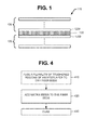
- a composite laminate 110 includes a plurality of fiber beds 120.
- a fiber bed 120 contains one or more rows of fibrous media.
- a fiber bed 120 includes one or more rows of continuous unidirectional reinforcing fibers.
- a fiber bed 120 includes a weave of continuous reinforcing fibers having different orientations.
- a fiber bed 120 includes a random mat, whose reinforcing fibers are discontinuous, randomly oriented, and overlapping.
- the composite laminate 110 may include one or more fiber beds 120 having fibers oriented at zero degrees with respect to a reference direction, and one or more fiber beds 120 having fibers oriented at a non-zero degree angle (e.g., 45 degrees, 90 degrees) with respect to the reference direction.
- Different fiber beds 120 of the composite laminate 110 may have the same types of fibers or different types of fibers. Fiber types may differ by size, modulus, composition, etc.
- the reinforcing fibers are embedded in a matrix.
- Different fiber beds 120 may have the same matrix composition or different compositions.
- the composite laminate 110 further includes at least one interlayer 130 (although only one interlayer 130 is illustrated, the composite laminate 110 may include at least one additional interlayer 130).
- An interlayer 130 is located between two adjacent fiber beds 120, which will be referred to as first and second fiber beds 120A and 120B.
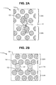
- FIGS. 2A and 2B both of which illustrate details of the first and second fiber beds 120A and 120B.
- Each fiber bed 120A and 120B includes reinforcing fibers 122 embedded in a matrix 124.
- FIGS. 2A and 2B also illustrate details of the interlayer 130.
- the interlayer 130 includes toughened regions 132 that extend between (i.e., bridge) the adjacent first and second fiber beds 120A and 120B in a through-plane direction.
- the toughened regions 132 are continuous in the through-plane direction.
- the toughened regions 132 are discontinuous in an in-plane direction ( FIGS. 2A and 2B both show toughened regions 132 that are discontinuous in the in-plane direction).
- the toughened regions 132 may have a size on the order of a few microns to a size on the order of a few millimeters. In other configurations described below (e.g., toughened regions 132 formed by films), the toughened regions 132 may be substantially larger and they may even be continuous.
- the toughened regions 132 are characterized as "toughened” because they are made of a material that is more resistant to crack propagation than the matrix 124. Toughness is a measure of the energy that can be absorbed in resistance to crack propagation. Toughness may be characterized by the GI and GII properties. As a first example, the composition of the matrix 124 is a thermoset, and the composition of the toughened regions 132 is a thermoplastic.
- the toughened regions 132 are fused to the fiber beds 120A and 120B. That is, each toughened region 132 has first and second ends fused to the first and second fiber beds 120A and 120B, respectively.
- FIG. 2A illustrates a configuration in which the toughened regions 132 are fused by mechanical interlocking. Opposite ends of the toughened regions 132 are mechanically interlocked with the first and second fiber beds 120A and 120B.
- the toughened regions 132 may infiltrate the fiber beds 120A and 120B and move around the reinforcing fibers 122.
- the thermoplastic material of the toughened regions 132 may fill spaces between reinforcing fibers 122 of the fiber beds 120A and 120B.
- FIG. 2B illustrates a configuration in which the toughened regions 132 are fused by bonding. Opposite ends of the toughened regions 132 are bonded to the first and second fiber beds 120A and 120B.
- the bonding may be covalent or non-covalent (e.g., hydrogen bonding).
- the toughened regions 132 may impede the propagation of through-plane cracks through the interlayer 130.
- the toughened regions 132 may impede the propagation of in-plane mode I cracks and in-plane mode II cracks.
- the in-plane mode I and mode II cracks include cracks along the edge of a fiber bed 120 (that is, the fiber-matrix interface at the interlayer 130), and cracks through the center of the fiber bed 120.
- Toughened regions 132 that are fused appear to be better at impeding in-plane crack propagation than toughened regions that are not fused.
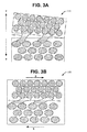
- FIG. 3A illustrates an in-plane mode I crack, where a tensile stress (T) is normal to the plane of the crack.
- FIG. 3B illustrates an in-plane mode II crack, where a shear stress (S) acts parallel to the plane of the crack and perpendicular to the crack front.
- the toughened regions 132 absorb energy and thereby impede crack propagation, thereby improving mode I and mode II performance of the composite laminate 110. Consequently, the toughened regions improve interlaminar toughness and impact properties.
- the toughened regions 132 are not limited to any particular configurations. Some configurations will be described below in connection with different methods of fabricating the composite laminate 110. These configurations include toughened regions 132 formed from particles, toughened regions 132 formed from filaments, and toughened regions 132 formed from films.
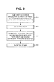
- FIG. 4 illustrates a general method of fabricating a composite laminate.
- a plurality of toughened regions of an interlayer are fused to dry fiber beds.
- the toughened regions are bonded to and/or mechanically interlocking with their fiber beds.
- matrix resin is added to the fiber beds after the fusing. That is, the fiber beds are impregnated with matrix resin.
- fusing to resin-impregnated fibers beds is ineffective. Therefore, the fusing is performed on the dry fiber beds, and the dry fiber beds are impregnated with resin after fusing. Moreover, fusing prior to curing reduces fiber bed distortion. Bending or otherwise distorting the reinforcing fibers can reduce the strength of the composite laminate. During curing, toughened regions made of thermoplastic may become soft and, therefore, will not push against the fiber beds to move the reinforcing fibers significantly.
- the form of the interlayer may also have an effect on fiber bending. Films, for instance, are flat and will apply even pressure during curing, resulting in minimal fiber bed distortion.
- the method of FIG. 4 may be implemented by forming a stack of dry fiber beds and interlayers, fusing the toughened regions to their adjacent dry fiber beds, impregnating the stack with matrix resin, and curing the stack.
- FIG. 5 illustrates a different implementation.
- the interlayer is formed by first and second portions.
- the first portion is fused to the first fiber bed, and the second portion is fused to the second fiber bed.
- matrix resin is added to the first and second fiber beds.
- a stack is formed with the first and second fiber beds.
- the first and second fiber beds are adjacent, with their fused portions in contact. That is, the first interlayer portion is in contact with the second interlayer portion.
- the stack may include a plurality of additional fiber beds.
- the stack may also include additional interlayers.
- the stack is cured. During curing, the first and second interlayer portions are fused together.
- FIG. 6 illustrates an example of an interlayer formed by first and second portions.
- Each interlayer portion 600 includes at least one partially soluble thermoplastic film 614 and an insoluble film 612.
- an interlayer portion 600 is placed on a fiber bed 120A, with the insoluble film 612 on the fiber bed 120A, and the partially soluble thermoplastic film 614 on the insoluble film 612. These two films 612 and 614 have through-holes 616, which are aligned.
- the insoluble film 612 is fused to its dry fiber bed 120A.
- Heat and pressure may be applied by a heated nip roller or other source.
- Heat without pressure may be applied by an infrared heater or other source.
- the fiber bed 120A is impregnated with matrix resin 632.
- the matrix resin 632 may be placed on the partially soluble film 614 and forced into the through-holes 616 and into the fiber bed 120A.
- Blocks 610-630 are repeated for the second fiber bed 120B.
- an uncured stack 642 is formed.
- the first and second fiber beds 120A and 120B are stacked up with their partially soluble thermoplastic films 614 in contact. Additional fiber beds and interlayers (not shown) may be added to the stack 642. At this stage, the stack 642 is ready for curing.
- the stack is cured to produce a composite laminate 110.
- the partially soluble films 614 blend with the matrix resin 632.
- each insoluble film 612 creates a region of high thermoplastic content
- each partially soluble film 614 creates a surrounding region of lower thermoplastic content.
- Interlayer thickness is controlled by thickness of the insoluble film 612 and the partially soluble film 614. The more that the partially soluble film 614 is dissolved, the thinner the interlayer 130 will be.
- the partially soluble film of a first portion of the interlayer may fuse to the first fiber bed during cure as autoclave pressure drives the materials together and the resin in the first fiber bed is slightly displaced.
- the partially soluble film of a second portion of the interlayer may fuse in the same way to a second fiber bed. In some regions the partially soluble film of a first portion of the interlayer will fuse to the partially soluble film of a second portion of the interlayer forming a toughened region extending between the first and second fiber beds and fused to the fiber beds.
- the partially soluble film may be omitted. Only insoluble films are formed on dry fibers beds, the insoluble films are fused to their dry fiber beds, the dry fiber beds are impregnated with matrix resin, a stack is formed, and the stack is cured. A thin layer of the impregnated matrix resin may form a bond between the two insoluble films, thus creating a continuous toughened region.
- thermoplastic particles are applied to a surface of each of the first and second dry fiber beds.
- the particles may be applied by dispersing the particles in a solvent, applying the solvent to both surfaces of the each fiber bed, and flashing off the solvent. Instead, the particles may be applied by a powder coating process or electrostatic deposition.
- the particles are fused to their first and second fiber beds.
- Heat and pressure may be applied by a heated nip roller.
- Heat without pressure may be applied by an infrared heater or other source.
- matrix resin is applied to the first and second fiber beds.
- an uncured stack is formed.
- the first and second fiber beds are stacked up with at least some of the particles fused to the first fiber bed making contact with particles fused to the second fiber bed.
- the stack may include additional fiber beds.
- the additional fiber beds may be pre-impregnated with matrix resin, or matrix resin may be impregnated with resin after stack up.
- the stack is cured. During curing, the contacting particles of the first and second fiber beds are fused together.
- FIG. 8 illustrates an example of an interlayer including filaments of thermoplastic material.
- one or more layers of thermoplastic filaments are deposited on each of first and second dry fiber beds.
- the filaments may be in the form of a veil, or they may be deposited as individual filaments.
- the filaments on the first fiber bed may have different angular orientations than the filaments on the second fiber bed.
- the filaments are fused to their respective fiber beds.
- the first and second fiber beds are impregnated with matrix resin.
- Matrix resin may also fill the spaces between the filaments in the interlayer.
- a stack is formed.
- the first and second fiber beds are stacked with the filaments on the first fiber bed making contact with the filaments on the second fiber bed.
- the stack may include additional fiber beds and interlayers.
- the stack is cured.
- the filaments on the opposing first and second fiber beds are fused together at their points of contact.
- FIG. 9A illustrates an example in which the filaments 910 on the first fiber bed 120A are oriented at 0 degrees, and the filaments 920 on the second fiber bed 120B are oriented at a different angle (e.g., 45 degrees).
- FIG. 9B illustrates that the filaments 910 and 920 are fused together at their points 930 of contact.
- the fiber beds 120A and 120B may have the same orientation as their filaments 910 and 920.
- the first fiber bed 120A may be oriented at 0 degrees
- the second fiber bed 120B may be oriented at that different angle.
- thermoplastic veil may be fused between the fiber beds.
- characteristics of an interlayer may be tailored. Interlayer characteristics may be tailored according to size and composition. Toughened regions formed by films may be tailored according to thickness and composition of the insoluble films and solubility of the partially soluble films.
- Interlayer characteristics may also be tailored according to spatial density of the toughened regions (the spatial density refers to the number of particles or filaments per unit area) and/or different compositions for the toughened regions.
- FIG. 10 illustrates one of many possible patterns for an interlayer 130: a checkerboard pattern.
- the darker portions 1010 represent a high density of toughened regions
- the lighter portions 1020 represent a low density of toughened regions.
- the darker portions 1010 provide maximum toughness while the lighter portions 1020 provide less toughness.
- FIG. 10 shows the portions 1010 and 1020 having rectangular shapes. Other shapes include, but are not limited to squares, diamonds, circles, and rectangles.
- FIG. 10 shows roughly fifty percent of the darker (higher density) portions 1010, and fifty percent of the lighter (lower density) portions 1020.
- the pattern is not limited to two distinct densities in equal proportions. Other patterns may have different relative percentages of the densities. Other patterns may have more than two distinct densities. Other patterns may provide progressive levels of densities.
- Different toughened regions may be made of different compositions by using different materials for the soluble coatings.
- the different coatings may have different inherent toughness values.
- An interlayer portion having higher toughness may be formed by using a higher density of filaments or particles having tougher coatings.
- an interlayer may include a pattern of high strength portions, lower strength, and high toughness portions.
- portions may be embedded within other portions.
- a high toughness portion may be surrounded by a high strength portion, which may be adjacent a lower strength portion.
Landscapes
- Engineering & Computer Science (AREA)
- Mechanical Engineering (AREA)
- Textile Engineering (AREA)
- Laminated Bodies (AREA)
Abstract
Description
- An impact to a composite laminate can cause cracks to initiate and propagate in or between fiber beds of the laminate. The cracks may be characterized as mode I cracks, mode II cracks, and mode III cracks.
- Interlayers between fiber beds may be used to impede the propagation of mode I, mode II and mode III cracks. For instance, the interlayers may include thermoplastic spheres or resin with a high thermoplastic content.
- According to an embodiment herein, a composite laminate comprises first and second fiber beds, and an interlayer between the fiber beds. The interlayer includes toughened regions that extend between the fiber beds and are fused to the fiber beds.
- According to another embodiment herein, a method comprises fabricating a composite laminate including fusing a plurality of thermoplastic regions of an interlayer to adjacent dry fiber beds.
- These features and functions may be achieved independently in various embodiments or may be combined in other embodiments. Further details of the embodiments can be seen with reference to the following description and drawings.
- Further, the disclosure comprises embodiments according to the following clauses:
- Clause 1. A composite laminate comprising: first and second fiber beds; and an interlayer between the fiber beds, the interlayer including toughened regions that extend between the fiber beds and are fused to the fiber beds.
- Clause 2. The laminate of clause 1, wherein the toughened regions are continuous in a through-plane direction and discontinuous in an in-plane direction.
- Clause 3. The laminate of any preceding claim, wherein the fiber beds include reinforcing fibers embedded in a matrix; and wherein the toughened regions are made of a material that is more resistant to crack propagation than the matrix.
- Clause 4. The laminate of clause 3, wherein composition of the matrix includes a thermoset, and composition of the toughened regions includes a thermoplastic.
- Clause 5. The laminate of any preceding claim, wherein the toughened regions are mechanically interlocked to the first and second fiber beds.
- Clause 6. The laminate of any preceding claim, wherein the toughened regions are bonded to the first and second fiber beds.
- Clause 7. The laminate of any preceding claim, wherein the toughened regions are formed by at least one thermoplastic film.
- Clause 8. The laminate of any preceding claim, wherein the toughened regions include thermoplastic particles.
- Clause 9. The laminate of any preceding claim, wherein the toughened regions include thermoplastic filaments.
- Clause 10. The laminate of any preceding claim, wherein the interlayer is patterned to provide a plurality of portions having different levels of resistance to crack propagation, the different portions having at least one of different spatial densities of toughened regions and different compositions for the toughened regions.
- Clause 11. A method comprising fabricating a composite laminate including fusing a plurality of thermoplastic regions of an interlayer to adjacent dry first and second fiber beds.
- Clause 12. The method of clause 11, wherein fabricating the composite laminate further includes adding matrix resin to the fiber beds after fusing the thermoplastic regions, and thereafter curing the matrix resin.
- Clause 13. The method of clauses 11-12, wherein the interlayer includes first and second portions; and the first portion is fused to the first fiber bed, the second portion is fused to the second fiber bed; and the fiber beds are stacked with the first and second portions making contact.
- Clause 14. The method of clause 13, wherein the first and second fiber beds are impregnated with matrix resin after the fusing but before the stacking.
- Clause 15. The method of clause 14, wherein fabricating the composite laminate further includes curing the stack, whereby the first and second portions of the interlayer are fused together.
- Clause 16. The method of clauses 14-15, wherein each portion includes an insoluble thermoplastic film, and a soluble thermoplastic film on the insoluble film; wherein each insoluble film is fused to its fiber bed; wherein matrix resin is infused into the fiber beds via through-holes in the films; and wherein the fiber beds are stacked with the soluble films making contact.
- Clause 17. The method of clause 16, further comprising curing the stack, whereby the soluble films blend with the matrix resin.
- Clause 18. The method of clauses 13-17, wherein the first portion includes first thermoplastic particles that are fused to the first fiber bed, and the second portion includes second thermoplastic particles that are fused to the second fiber bed; and wherein at least some of the first and second particles make contact when the first and second fiber beds are stacked.
- Clause 19. The method of clauses 13-18, wherein the first portion includes first thermoplastic filaments that are fused to the first fiber bed, and the second portion includes second thermoplastic filaments that are fused to the second fiber bed; and wherein the first and second filaments make contact when the first and second fiber beds are stacked.
- Clause 20. The method of clause 19, wherein the first filaments and the first fiber bed are oriented at a first angle, and the second filaments and the second fiber bed are oriented at a second angle.
-
-
FIG. 1 is an illustration of a composite laminate including first and second fiber beds, and an interlayer between the fiber beds. -
FIG. 2A is an illustration of an interlayer having toughened regions that are mechanically interlocked with adjacent fiber beds. -
FIG. 2B is an illustration of an interlayer having toughened regions that are bonded to adjacent fiber beds. -
FIGS. 3A and 3B are illustrations of toughened regions in the interlayer with respect to mode I and mode II cracks. -
FIG. 4 is an illustration of a general method of fabricating a composite laminate including an interlayer having toughened regions. -
FIG. 5 is an illustration of an example of a method of fabricating a composite laminate including an interlayer having toughened regions. -
FIG. 6 is an illustration of a method of fabricating a composite laminate including an interlayer from partially soluble thermoplastic films and insoluble thermoplastic films. -
FIG. 7 is an illustration of a method of fabricating a composite laminate including an interlayer from particles of thermoplastic material. -
FIG. 8 is an illustration of a method of fabricating a composite laminate including an interlayer from filaments of thermoplastic material. -
FIGS. 9A and 9B are illustrations of an interlayer including first and second layers of filaments oriented at different angles. -
FIG. 10 is an illustration of a composite laminate having interlayers patterned for selective toughness. - Referring to
FIG. 1 , acomposite laminate 110 includes a plurality offiber beds 120. Afiber bed 120 contains one or more rows of fibrous media. As a first example, afiber bed 120 includes one or more rows of continuous unidirectional reinforcing fibers. As a second example, afiber bed 120 includes a weave of continuous reinforcing fibers having different orientations. As a third example, afiber bed 120 includes a random mat, whose reinforcing fibers are discontinuous, randomly oriented, and overlapping. - In some configurations, all reinforcing fibers in all of the
fiber beds 120 extend in the same direction. In other configurations, the reinforcing fibers of somefiber beds 120 extend in different directions than the reinforcing fibers ofother fiber beds 120. For example, thecomposite laminate 110 may include one ormore fiber beds 120 having fibers oriented at zero degrees with respect to a reference direction, and one ormore fiber beds 120 having fibers oriented at a non-zero degree angle (e.g., 45 degrees, 90 degrees) with respect to the reference direction. -
Different fiber beds 120 of thecomposite laminate 110 may have the same types of fibers or different types of fibers. Fiber types may differ by size, modulus, composition, etc. - The reinforcing fibers are embedded in a matrix.
Different fiber beds 120 may have the same matrix composition or different compositions. - The
composite laminate 110 further includes at least one interlayer 130 (although only oneinterlayer 130 is illustrated, thecomposite laminate 110 may include at least one additional interlayer 130). Aninterlayer 130 is located between twoadjacent fiber beds 120, which will be referred to as first andsecond fiber beds - Additional reference is made to
FIGS. 2A and 2B , both of which illustrate details of the first andsecond fiber beds fiber bed fibers 122 embedded in amatrix 124. -
FIGS. 2A and 2B also illustrate details of theinterlayer 130. Theinterlayer 130 includes toughenedregions 132 that extend between (i.e., bridge) the adjacent first andsecond fiber beds regions 132 are continuous in the through-plane direction. In some configurations, the toughenedregions 132 are discontinuous in an in-plane direction (FIGS. 2A and 2B both show toughenedregions 132 that are discontinuous in the in-plane direction). In some configurations described below (e.g., toughenedregions 132 formed by fused particles, and toughenedregions 132 formed by overlapping filaments), the toughenedregions 132 may have a size on the order of a few microns to a size on the order of a few millimeters. In other configurations described below (e.g., toughenedregions 132 formed by films), the toughenedregions 132 may be substantially larger and they may even be continuous. - The toughened
regions 132 are characterized as "toughened" because they are made of a material that is more resistant to crack propagation than thematrix 124. Toughness is a measure of the energy that can be absorbed in resistance to crack propagation. Toughness may be characterized by the GI and GII properties. As a first example, the composition of thematrix 124 is a thermoset, and the composition of the toughenedregions 132 is a thermoplastic. - The toughened
regions 132 are fused to thefiber beds region 132 has first and second ends fused to the first andsecond fiber beds -
FIG. 2A illustrates a configuration in which the toughenedregions 132 are fused by mechanical interlocking. Opposite ends of the toughenedregions 132 are mechanically interlocked with the first andsecond fiber beds regions 132 may infiltrate thefiber beds fibers 122. For example, the thermoplastic material of the toughenedregions 132 may fill spaces between reinforcingfibers 122 of thefiber beds -
FIG. 2B illustrates a configuration in which the toughenedregions 132 are fused by bonding. Opposite ends of the toughenedregions 132 are bonded to the first andsecond fiber beds - The toughened
regions 132 may impede the propagation of through-plane cracks through theinterlayer 130. The toughenedregions 132 may impede the propagation of in-plane mode I cracks and in-plane mode II cracks. The in-plane mode I and mode II cracks include cracks along the edge of a fiber bed 120 (that is, the fiber-matrix interface at the interlayer 130), and cracks through the center of thefiber bed 120. - The applicants have found that fusing the toughened
regions 132 to thefiber beds 120 improves the mode I and mode II performance with respect to in-plane cracks. Toughenedregions 132 that are fused appear to be better at impeding in-plane crack propagation than toughened regions that are not fused. -
FIG. 3A illustrates an in-plane mode I crack, where a tensile stress (T) is normal to the plane of the crack.FIG. 3B illustrates an in-plane mode II crack, where a shear stress (S) acts parallel to the plane of the crack and perpendicular to the crack front. The toughenedregions 132 absorb energy and thereby impede crack propagation, thereby improving mode I and mode II performance of thecomposite laminate 110. Consequently, the toughened regions improve interlaminar toughness and impact properties. - The toughened
regions 132 are not limited to any particular configurations. Some configurations will be described below in connection with different methods of fabricating thecomposite laminate 110. These configurations include toughenedregions 132 formed from particles, toughenedregions 132 formed from filaments, and toughenedregions 132 formed from films. - Reference is made to
FIG. 4 , which illustrates a general method of fabricating a composite laminate. Atblock 410, a plurality of toughened regions of an interlayer are fused to dry fiber beds. The toughened regions are bonded to and/or mechanically interlocking with their fiber beds. - At
block 420, matrix resin is added to the fiber beds after the fusing. That is, the fiber beds are impregnated with matrix resin. - At
block 430, curing is performed. As a result of curing, the reinforcing fibers of the fiber beds are embedded in a matrix. The toughened regions are more resistant to crack propagation than the matrix. - The applicants have found that fusing to resin-impregnated fibers beds is ineffective. Therefore, the fusing is performed on the dry fiber beds, and the dry fiber beds are impregnated with resin after fusing. Moreover, fusing prior to curing reduces fiber bed distortion. Bending or otherwise distorting the reinforcing fibers can reduce the strength of the composite laminate. During curing, toughened regions made of thermoplastic may become soft and, therefore, will not push against the fiber beds to move the reinforcing fibers significantly.
- The form of the interlayer may also have an effect on fiber bending. Films, for instance, are flat and will apply even pressure during curing, resulting in minimal fiber bed distortion.
- The method of
FIG. 4 may be implemented by forming a stack of dry fiber beds and interlayers, fusing the toughened regions to their adjacent dry fiber beds, impregnating the stack with matrix resin, and curing the stack. However,FIG. 5 illustrates a different implementation. - Referring to
FIG. 5 , the interlayer is formed by first and second portions. Atblock 510, the first portion is fused to the first fiber bed, and the second portion is fused to the second fiber bed. Atblock 520, matrix resin is added to the first and second fiber beds. - At
block 530, a stack is formed with the first and second fiber beds. The first and second fiber beds are adjacent, with their fused portions in contact. That is, the first interlayer portion is in contact with the second interlayer portion. - The stack may include a plurality of additional fiber beds. The stack may also include additional interlayers.
- At
block 540, the stack is cured. During curing, the first and second interlayer portions are fused together. -
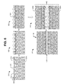
FIG. 6 illustrates an example of an interlayer formed by first and second portions. Eachinterlayer portion 600 includes at least one partiallysoluble thermoplastic film 614 and aninsoluble film 612. - At
block 610, aninterlayer portion 600 is placed on afiber bed 120A, with theinsoluble film 612 on thefiber bed 120A, and the partiallysoluble thermoplastic film 614 on theinsoluble film 612. These twofilms holes 616, which are aligned. - At
block 620, theinsoluble film 612 is fused to itsdry fiber bed 120A. Heat and pressure may be applied by a heated nip roller or other source. Heat without pressure may be applied by an infrared heater or other source. - At
block 630, thefiber bed 120A is impregnated withmatrix resin 632. Thematrix resin 632 may be placed on the partiallysoluble film 614 and forced into the through-holes 616 and into thefiber bed 120A. - Blocks 610-630 are repeated for the
second fiber bed 120B. - At
block 640, anuncured stack 642 is formed. The first andsecond fiber beds thermoplastic films 614 in contact. Additional fiber beds and interlayers (not shown) may be added to thestack 642. At this stage, thestack 642 is ready for curing. - At
block 650, the stack is cured to produce acomposite laminate 110. During curing, the partiallysoluble films 614 blend with thematrix resin 632. Thus, eachinsoluble film 612 creates a region of high thermoplastic content, and each partiallysoluble film 614 creates a surrounding region of lower thermoplastic content. - Interlayer thickness is controlled by thickness of the
insoluble film 612 and the partiallysoluble film 614. The more that the partiallysoluble film 614 is dissolved, the thinner theinterlayer 130 will be. - In another example, the partially soluble film of a first portion of the interlayer may fuse to the first fiber bed during cure as autoclave pressure drives the materials together and the resin in the first fiber bed is slightly displaced. The partially soluble film of a second portion of the interlayer may fuse in the same way to a second fiber bed. In some regions the partially soluble film of a first portion of the interlayer will fuse to the partially soluble film of a second portion of the interlayer forming a toughened region extending between the first and second fiber beds and fused to the fiber beds.
- In another example, the partially soluble film may be omitted. Only insoluble films are formed on dry fibers beds, the insoluble films are fused to their dry fiber beds, the dry fiber beds are impregnated with matrix resin, a stack is formed, and the stack is cured. A thin layer of the impregnated matrix resin may form a bond between the two insoluble films, thus creating a continuous toughened region.
- Reference is made to
FIG. 7 , which illustrates an example of an interlayer including particles of thermoplastic material. Atblock 710, thermoplastic particles are applied to a surface of each of the first and second dry fiber beds. The particles may be applied by dispersing the particles in a solvent, applying the solvent to both surfaces of the each fiber bed, and flashing off the solvent. Instead, the particles may be applied by a powder coating process or electrostatic deposition. - At
block 720, the particles are fused to their first and second fiber beds. Heat and pressure may be applied by a heated nip roller. Heat without pressure may be applied by an infrared heater or other source. - At
block 730, matrix resin is applied to the first and second fiber beds. - At
block 740, an uncured stack is formed. The first and second fiber beds are stacked up with at least some of the particles fused to the first fiber bed making contact with particles fused to the second fiber bed. - The stack may include additional fiber beds. The additional fiber beds may be pre-impregnated with matrix resin, or matrix resin may be impregnated with resin after stack up.
- At
block 750, the stack is cured. During curing, the contacting particles of the first and second fiber beds are fused together. - Reference is made to
FIG. 8 , which illustrates an example of an interlayer including filaments of thermoplastic material. Atblock 810, one or more layers of thermoplastic filaments are deposited on each of first and second dry fiber beds. The filaments may be in the form of a veil, or they may be deposited as individual filaments. The filaments on the first fiber bed may have different angular orientations than the filaments on the second fiber bed. - At
block 820, the filaments are fused to their respective fiber beds. Atblock 830, the first and second fiber beds are impregnated with matrix resin. Matrix resin may also fill the spaces between the filaments in the interlayer. - At
block 840, a stack is formed. The first and second fiber beds are stacked with the filaments on the first fiber bed making contact with the filaments on the second fiber bed. The stack may include additional fiber beds and interlayers. - At
block 850, the stack is cured. The filaments on the opposing first and second fiber beds are fused together at their points of contact. -
FIG. 9A illustrates an example in which thefilaments 910 on thefirst fiber bed 120A are oriented at 0 degrees, and thefilaments 920 on thesecond fiber bed 120B are oriented at a different angle (e.g., 45 degrees).FIG. 9B illustrates that thefilaments points 930 of contact. Thefiber beds filaments FIG. 9A , thefirst fiber bed 120A may be oriented at 0 degrees, and thesecond fiber bed 120B may be oriented at that different angle. - In another example, a single ply of thermoplastic veil may be fused between the fiber beds.
- In each of the examples above, characteristics of an interlayer may be tailored. Interlayer characteristics may be tailored according to size and composition. Toughened regions formed by films may be tailored according to thickness and composition of the insoluble films and solubility of the partially soluble films.
- Interlayer characteristics may also be tailored according to spatial density of the toughened regions (the spatial density refers to the number of particles or filaments per unit area) and/or different compositions for the toughened regions.
- An interlayer may be patterned to provide different levels of toughness. Consider the example in
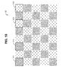
FIG. 10. FIG. 10 illustrates one of many possible patterns for an interlayer 130: a checkerboard pattern. For theinterlayer 130 ofFIG. 10 , thedarker portions 1010 represent a high density of toughened regions, and thelighter portions 1020 represent a low density of toughened regions. Thedarker portions 1010 provide maximum toughness while thelighter portions 1020 provide less toughness. -
FIG. 10 shows theportions -
FIG. 10 shows roughly fifty percent of the darker (higher density)portions 1010, and fifty percent of the lighter (lower density)portions 1020. However, the pattern is not limited to two distinct densities in equal proportions. Other patterns may have different relative percentages of the densities. Other patterns may have more than two distinct densities. Other patterns may provide progressive levels of densities. - Different toughened regions may be made of different compositions by using different materials for the soluble coatings. The different coatings may have different inherent toughness values. An interlayer portion having higher toughness may be formed by using a higher density of filaments or particles having tougher coatings.
- Some patterns may have portions that are also tailored according to modulus and/or strength. For example, an interlayer may include a pattern of high strength portions, lower strength, and high toughness portions.
- In some patterns, portions may be embedded within other portions. For instance, a high toughness portion may be surrounded by a high strength portion, which may be adjacent a lower strength portion.
Claims (15)
- A composite laminate comprising:first and second fiber beds; andan interlayer between the fiber beds, the interlayer including toughened regions that extend between the fiber beds and are fused to the fiber beds.
- The laminate of claim 1, wherein the toughened regions are continuous in a through-plane direction and discontinuous in an in-plane direction.
- The laminate of any preceding claim, wherein the fiber beds include reinforcing fibers embedded in a matrix; and wherein the toughened regions are made of a material that is more resistant to crack propagation than the matrix.
- The laminate of any preceding claim, wherein the toughened regions are mechanically interlocked to the first and second fiber beds.
- The laminate of any preceding claim, wherein the toughened regions are bonded to the first and second fiber beds.
- The laminate of any preceding claim, wherein the toughened regions include thermoplastic particles.
- The laminate of any preceding claim, wherein the toughened regions include thermoplastic filaments.
- A method comprising fabricating a composite laminate including fusing a plurality of thermoplastic regions of an interlayer to adjacent dry first and second fiber beds.
- The method of claim 8, wherein fabricating the composite laminate further includes adding matrix resin to the fiber beds after fusing the thermoplastic regions, and thereafter curing the matrix resin.
- The method of claims 8-9, wherein the interlayer includes first and second portions; and the first portion is fused to the first fiber bed, the second portion is fused to the second fiber bed; and the fiber beds are stacked with the first and second portions making contact.
- The method of claims 8-10, wherein the first and second fiber beds are impregnated with matrix resin after the fusing but before the stacking.
- The method of claim 11, wherein fabricating the composite laminate further includes curing the stack, whereby the first and second portions of the interlayer are fused together.
- The method of claim 10, wherein the first portion includes first thermoplastic particles that are fused to the first fiber bed, and the second portion includes second thermoplastic particles that are fused to the second fiber bed; and wherein at least some of the first and second particles make contact when the first and second fiber beds are stacked.
- The method of claim 10, wherein the first portion includes first thermoplastic filaments that are fused to the first fiber bed, and the second portion includes second thermoplastic filaments that are fused to the second fiber bed; and wherein the first and second filaments make contact when the first and second fiber beds are stacked.
- The method of claim 14, wherein the first filaments and the first fiber bed are oriented at a first angle, and the second filaments and the second fiber bed are oriented at a second angle.
Applications Claiming Priority (1)
| Application Number | Priority Date | Filing Date | Title |
|---|---|---|---|
| US14/553,553 US9821530B2 (en) | 2014-11-25 | 2014-11-25 | Composite laminate including interlayers with through-plane regions fused to fiber beds |
Publications (1)
| Publication Number | Publication Date |
|---|---|
| EP3025853A1 true EP3025853A1 (en) | 2016-06-01 |
Family
ID=54557230
Family Applications (1)
| Application Number | Title | Priority Date | Filing Date |
|---|---|---|---|
| EP15192574.0A Ceased EP3025853A1 (en) | 2014-11-25 | 2015-11-02 | Composite laminate including interlayers with through-plane regions fused to fiber beds |
Country Status (4)
| Country | Link |
|---|---|
| US (1) | US9821530B2 (en) |
| EP (1) | EP3025853A1 (en) |
| JP (1) | JP6646974B2 (en) |
| CN (1) | CN105619905B (en) |
Families Citing this family (4)
| Publication number | Priority date | Publication date | Assignee | Title |
|---|---|---|---|---|
| CN113767007A (en) | 2019-05-23 | 2021-12-07 | 东丽株式会社 | Method for producing fiber-reinforced resin base material, and integrated molded article thereof |
| CN114761468B (en) * | 2019-12-11 | 2024-10-15 | 东丽株式会社 | Prepregs, laminates and integrated moldings |
| US20230001651A1 (en) * | 2019-12-11 | 2023-01-05 | Toray Industries, Inc. | Prepreg, laminate, and integrated product |
| CN117719220B (en) * | 2024-01-24 | 2026-03-17 | 北京理工大学 | An impact-resistant composite laminate and its preparation method |
Citations (4)
| Publication number | Priority date | Publication date | Assignee | Title |
|---|---|---|---|---|
| US20100086764A1 (en) * | 2008-10-07 | 2010-04-08 | The Boeing Company | Composite Material Structure with Interlayer Electrical Conductance |
| US20120156422A1 (en) * | 2010-12-15 | 2012-06-21 | The Boeing Company | Selectively coupled fibers in composites |
| EP2653293A1 (en) * | 2012-04-19 | 2013-10-23 | The Boeing Company | Composite articles having fibers with longitudinally-varying geometry |
| US20140151507A1 (en) * | 2012-12-03 | 2014-06-05 | The Boeing Company | Split Resistant Composite Laminate |
Family Cites Families (15)
| Publication number | Priority date | Publication date | Assignee | Title |
|---|---|---|---|---|
| EP0327142B1 (en) * | 1984-03-30 | 1996-01-10 | Cytec Technology Corp. | Resin matrix composites |
| US4537610A (en) * | 1984-05-24 | 1985-08-27 | Owens-Corning Fiberglas Corporation | Method and apparatus for producing chopped strands |
| DE19647671A1 (en) * | 1996-11-19 | 1998-05-28 | Deutsch Zentr Luft & Raumfahrt | Fibre reinforced composite material useful for production of press moulded structural elements |
| GB0024060D0 (en) * | 2000-10-02 | 2000-11-15 | Matrice Material Systems Ltd | A composite |
| US6989197B2 (en) * | 2002-11-04 | 2006-01-24 | The Boeing Company | Polymer composite structure reinforced with shape memory alloy and method of manufacturing same |
| JP4333178B2 (en) * | 2003-03-26 | 2009-09-16 | 東レ株式会社 | Manufacturing method of fiber reinforced composite material |
| JP5077731B2 (en) * | 2005-03-25 | 2012-11-21 | 東レ株式会社 | Energy absorbing member |
| JP5029072B2 (en) * | 2006-03-15 | 2012-09-19 | 東レ株式会社 | Reinforced fiber substrate laminate and method for producing the same |
| GB0805640D0 (en) | 2008-03-28 | 2008-04-30 | Hexcel Composites Ltd | Improved composite materials |
| US8470923B2 (en) | 2010-04-21 | 2013-06-25 | Hexcel Corporation | Composite material for structural applications |
| US8686069B2 (en) | 2010-10-12 | 2014-04-01 | Hexcel Corporation | Solvent resistance of epoxy resins toughened with polyethersulfone |
| US8796164B2 (en) | 2010-12-28 | 2014-08-05 | Cytec Technology Corp. | Multilayer and composition gradient structures with improved damping properties |
| US9187636B2 (en) * | 2012-08-26 | 2015-11-17 | Hexcel Corporation | Composite material with polyamide particle mixtures |
| IN2015DN04167A (en) * | 2012-11-16 | 2015-10-16 | Bayer Materialscience Llc | |
| TWI504510B (en) * | 2012-12-20 | 2015-10-21 | Compal Electronics Inc | Composite material and method of forming the same |
-
2014
- 2014-11-25 US US14/553,553 patent/US9821530B2/en active Active
-
2015
- 2015-08-07 JP JP2015156864A patent/JP6646974B2/en active Active
- 2015-11-02 EP EP15192574.0A patent/EP3025853A1/en not_active Ceased
- 2015-11-24 CN CN201510825045.7A patent/CN105619905B/en active Active
Patent Citations (4)
| Publication number | Priority date | Publication date | Assignee | Title |
|---|---|---|---|---|
| US20100086764A1 (en) * | 2008-10-07 | 2010-04-08 | The Boeing Company | Composite Material Structure with Interlayer Electrical Conductance |
| US20120156422A1 (en) * | 2010-12-15 | 2012-06-21 | The Boeing Company | Selectively coupled fibers in composites |
| EP2653293A1 (en) * | 2012-04-19 | 2013-10-23 | The Boeing Company | Composite articles having fibers with longitudinally-varying geometry |
| US20140151507A1 (en) * | 2012-12-03 | 2014-06-05 | The Boeing Company | Split Resistant Composite Laminate |
Also Published As
| Publication number | Publication date |
|---|---|
| JP6646974B2 (en) | 2020-02-14 |
| JP2016097676A (en) | 2016-05-30 |
| US20160144595A1 (en) | 2016-05-26 |
| CN105619905A (en) | 2016-06-01 |
| CN105619905B (en) | 2019-08-13 |
| US9821530B2 (en) | 2017-11-21 |
Similar Documents
| Publication | Publication Date | Title |
|---|---|---|
| US12188160B2 (en) | Filament network for a composite structure | |
| US8916252B2 (en) | Structural longitudinal composite joint for aircraft structure | |
| JP5320742B2 (en) | Method for producing composite prepreg substrate, laminated substrate and fiber reinforced plastic | |
| JP7393852B2 (en) | Placement of modified materials within resin-rich pockets to reduce microcrack formation in composite structures | |
| CN113427841B (en) | Hybrid Veils as Interlayers in Composite Materials | |
| JP7182845B2 (en) | Addition of polymer nanoparticles in the field of resin modification | |
| JP2006501085A (en) | Manufacturing method of composite material | |
| US20160159998A1 (en) | Prepreg for manufacturing composite materials | |
| JP2021502272A5 (en) | ||
| US9821530B2 (en) | Composite laminate including interlayers with through-plane regions fused to fiber beds | |
| CN105751659B (en) | Method of manufacturing a composite laminate and article for manufacturing a composite laminate | |
| JP7466468B2 (en) | Ultra-thin prepreg sheet and its composite material | |
| JPH0583072B2 (en) | ||
| CN116194278A (en) | Fiber-reinforced plastic and method for producing fiber-reinforced plastic | |
| JP2005262818A (en) | Reinforcing fiber substrate, preform and method for producing reinforcing fiber substrate | |
| JP2006138031A (en) | Reinforcing fiber substrate, preform, and production method thereof | |
| WO2025249368A1 (en) | Blade, method for manufacturing same, and flying body | |
| GB2621380A (en) | A resin layer for use in composite materials | |
| JP2003311863A (en) | Glass fiber substrate for smooth surface laminate, and method for producing the same |
Legal Events
| Date | Code | Title | Description |
|---|---|---|---|
| PUAI | Public reference made under article 153(3) epc to a published international application that has entered the european phase |
Free format text: ORIGINAL CODE: 0009012 |
|
| 17P | Request for examination filed |
Effective date: 20151102 |
|
| AK | Designated contracting states |
Kind code of ref document: A1 Designated state(s): AL AT BE BG CH CY CZ DE DK EE ES FI FR GB GR HR HU IE IS IT LI LT LU LV MC MK MT NL NO PL PT RO RS SE SI SK SM TR |
|
| AX | Request for extension of the european patent |
Extension state: BA ME |
|
| STAA | Information on the status of an ep patent application or granted ep patent |
Free format text: STATUS: EXAMINATION IS IN PROGRESS |
|
| 17Q | First examination report despatched |
Effective date: 20180607 |
|
| STAA | Information on the status of an ep patent application or granted ep patent |
Free format text: STATUS: THE APPLICATION HAS BEEN REFUSED |
|
| 18R | Application refused |
Effective date: 20220718 |