EP3025677A1 - Intraocular-lens-inserting instrument - Google Patents
Intraocular-lens-inserting instrument Download PDFInfo
- Publication number
- EP3025677A1 EP3025677A1 EP14828661.0A EP14828661A EP3025677A1 EP 3025677 A1 EP3025677 A1 EP 3025677A1 EP 14828661 A EP14828661 A EP 14828661A EP 3025677 A1 EP3025677 A1 EP 3025677A1
- Authority
- EP
- European Patent Office
- Prior art keywords
- intraocular lens
- fore
- nozzle body
- insertion apparatus
- axis
- Prior art date
- Legal status (The legal status is an assumption and is not a legal conclusion. Google has not performed a legal analysis and makes no representation as to the accuracy of the status listed.)
- Withdrawn
Links
Images










Classifications
-
- A—HUMAN NECESSITIES
- A61—MEDICAL OR VETERINARY SCIENCE; HYGIENE
- A61F—FILTERS IMPLANTABLE INTO BLOOD VESSELS; PROSTHESES; DEVICES PROVIDING PATENCY TO, OR PREVENTING COLLAPSING OF, TUBULAR STRUCTURES OF THE BODY, e.g. STENTS; ORTHOPAEDIC, NURSING OR CONTRACEPTIVE DEVICES; FOMENTATION; TREATMENT OR PROTECTION OF EYES OR EARS; BANDAGES, DRESSINGS OR ABSORBENT PADS; FIRST-AID KITS
- A61F2/00—Filters implantable into blood vessels; Prostheses, i.e. artificial substitutes or replacements for parts of the body; Appliances for connecting them with the body; Devices providing patency to, or preventing collapsing of, tubular structures of the body, e.g. stents
- A61F2/02—Prostheses implantable into the body
- A61F2/14—Eye parts, e.g. lenses or corneal implants; Artificial eyes
- A61F2/16—Intraocular lenses
- A61F2/1662—Instruments for inserting intraocular lenses into the eye
- A61F2/167—Instruments for inserting intraocular lenses into the eye with pushable plungers
-
- A—HUMAN NECESSITIES
- A61—MEDICAL OR VETERINARY SCIENCE; HYGIENE
- A61F—FILTERS IMPLANTABLE INTO BLOOD VESSELS; PROSTHESES; DEVICES PROVIDING PATENCY TO, OR PREVENTING COLLAPSING OF, TUBULAR STRUCTURES OF THE BODY, e.g. STENTS; ORTHOPAEDIC, NURSING OR CONTRACEPTIVE DEVICES; FOMENTATION; TREATMENT OR PROTECTION OF EYES OR EARS; BANDAGES, DRESSINGS OR ABSORBENT PADS; FIRST-AID KITS
- A61F2/00—Filters implantable into blood vessels; Prostheses, i.e. artificial substitutes or replacements for parts of the body; Appliances for connecting them with the body; Devices providing patency to, or preventing collapsing of, tubular structures of the body, e.g. stents
- A61F2/02—Prostheses implantable into the body
- A61F2/14—Eye parts, e.g. lenses or corneal implants; Artificial eyes
- A61F2/16—Intraocular lenses
- A61F2/1662—Instruments for inserting intraocular lenses into the eye
-
- A—HUMAN NECESSITIES
- A61—MEDICAL OR VETERINARY SCIENCE; HYGIENE
- A61F—FILTERS IMPLANTABLE INTO BLOOD VESSELS; PROSTHESES; DEVICES PROVIDING PATENCY TO, OR PREVENTING COLLAPSING OF, TUBULAR STRUCTURES OF THE BODY, e.g. STENTS; ORTHOPAEDIC, NURSING OR CONTRACEPTIVE DEVICES; FOMENTATION; TREATMENT OR PROTECTION OF EYES OR EARS; BANDAGES, DRESSINGS OR ABSORBENT PADS; FIRST-AID KITS
- A61F2/00—Filters implantable into blood vessels; Prostheses, i.e. artificial substitutes or replacements for parts of the body; Appliances for connecting them with the body; Devices providing patency to, or preventing collapsing of, tubular structures of the body, e.g. stents
- A61F2/02—Prostheses implantable into the body
- A61F2/14—Eye parts, e.g. lenses or corneal implants; Artificial eyes
- A61F2/16—Intraocular lenses
- A61F2/1662—Instruments for inserting intraocular lenses into the eye
- A61F2/1678—Instruments for inserting intraocular lenses into the eye with a separate cartridge or other lens setting part for storage of a lens, e.g. preloadable for shipping
Definitions
- the embodiments discussed herein pertain to an intraocular lens insertion apparatus.
- Intraocular lenses are widely used to be replaced with human opacity crystalline lenses in cataract treatments ornormal human crystalline lenses for compensating the optical powers of the lenses.
- intraocular lens insertion surgeries for the cataract treatments a discission wound which is several millimeters in length is produced at the edge of the cornea, the human crystalline lens is crushed and removed by phacoemulsification and aspiration etc. and the intraocular lens is inserted and fixed in the eye, for example.
- Polymethyl methacrylate (PMMA), acrylic resin, silicon resin etc. are used as the material of the intraocular lens.
- the structure of the intraocular lens can be divided into an optical member and a supporting member.
- the intraocular lens is enclosed in a dedicated intraocular lens insertion apparatus.
- the intraocular lens insertion apparatus is taken out from the package of the apparatus in an asepticmanner, and the tip of the insertion apparatus is inserted into the eye from the discission wound and the insertion apparatus is handled to guide the intraocular lens into the human crystalline lens capsule.
- the insertion apparatus is configured to eject the intraocular lens into the eye in a folded state.
- patent document 1 discloses a structure in which the opening of the tip of the insertion apparatus is configured to have an oblique surface oblique to the longitudinal direction of the opening.
- a roof is provided for the tip of the opening. The roof functions to open the wound when the tip of the insertion apparatus is inserted into the wound.
- patent document 2 discloses a structure in which the end surface of the opening of the tip of the insertion apparatus is formed in a curved shape. Therefore, the possibility that the insertion apparatus unnecessarily stimulates the eye tissues can be reduced since the opening in the curved shape can make a smooth contact with the wound etc. when the tip of the insertion apparatus is inserted into the wound.
- the insertion apparatus with the opening having the shape as described in the above patent documents may face a difficulty in insert the opening into a predetermined position in the discission wound.
- the intraocular lens may go out from a part of the opening which is located outside of the discission wound and then the intraocular lens cannot be inserted into the eye.
- One aspect of the present invention lies in providing an insertion apparatus which prevents an intraocular lens from going out to the outside of the eye and ensures a secure insertion of the intraocular lens into the eye when the insertion apparatus is inserted a discission wound which is smaller than that of conventional discission wounds.
- an intraocular lens insertion apparatus including a cylindrical body member configured to retain an intraocular lens, a fore-end opening provided for a tip of the body member, and a planate protrusion provided for a tip of the fore-end opening, wherein an end surface of the fore-end opening is an oblique surface which is oblique to a plane perpendicular to a central axis of the body member, and a fore-end area including a pair of lateral walls which are parallel to each other across the central axis is formed on a side of the tip of the fore-end opening.
- the insertion apparatus can be inserted into a discission wound smaller than conventional discission wounds, can prevent the intraocular lens from going out of the eye from the insertion apparatus and can stably retain and guide the intraocular lens into the human crystalline capsule.
- the intraocular lens insertion apparatus can be configured to achieve that a back-end area which is connected with a back end of the fore-end area is formed on a side of a back end of the fore-end opening, and an angle of gradient of an oblique surface in the fore-end area to a plane perpendicular to the central axis is smaller than an angle of gradient of an oblique surface in the back-end area to a plane perpendicular to the central axis.
- the contour of the fore-end opening in a side view can include an inflection point between the fore-end area and the back-end area.
- the lateral walls in the fore-end area in the side view are configured to rise at a steep angle and therefore the intraocular lens can be more stably retained by the lateral walls than the conventional insertion apparatus. Therefore, the intraocular lens can be prevented from going out of the eye from the fore-end opening when the intraocular lens is guided into the human crystalline capsule.
- the intraocular lens insertion apparatus can be configured to achieve that the shape of the fore-end opening is tapering toward the tip of the fore-end opening. Therefore, the tip of the fore-end opening can be more easily inserted into the eye than conventional insertion apparatuses after the insertion apparatus is inserted into the small discission wound.
- the body member can include a positioning member for positioning the intraocular lens, and the intraocular lens can be positioned by the positioning member in the body member in advance.
- an insertion apparatus which prevents an intraocular lens from going out to the outside of the eye and ensures a secure insertion of the intraocular lens into the eye when the insertion apparatus is inserted a discission wound which is smaller than that of a conventional discission wound can be achieved.
- the intraocular lens insertion apparatus 1 includes a nozzle body 100, a stage member 200 and a plunger 300.
- the nozzle body 100 is formed into a shape similar to an elongated tube and a hollow space is provided over the entire length of the nozzle body 100. It is noted that the nozzle body 100 corresponds to an example of the body of the intraocular lens insertion apparatus.
- the cross-section of the nozzle body 100 formed by a surface which is vertical to the longitudinal direction of the nozzle body 100 is approximately rectangular.
- an intraocular lens 2 is retained in the nozzle body 100 by the stage member.
- the plunger 300 is a bar member which is elongated tube in shape. The plunger 300 is partially inserted into the tube portion of the nozzle body 100.
- the plunger 300 is used as a push member used for guiding the intraocular lens 2 into the human crystalline lens capsule.
- the Z axis is set so that the direction of the Z axis is parallel to the longitude direction of the insertion apparatus 1 and the direction of the Z axis going from the back end to the front end of the nozzle body 100 is the positive direction.
- the X axis and the Y axis are set to bisect each other at right angles and to be perpendicular to the Z axis.
- the X axis corresponds to the optic axis of the intraocular lens 2 which is set by the positioning member 210 in the nozzle body 100.
- the Z axis is parallel to the direction in which the plunger 300 inserted into the nozzle body 100 is pushed.
- a surface provided in the negative side of the X axis is referred to as a bottom surface and that a surface provided in the positive side of the X axis is referred to an upper surface in some cases.
- the positive side of the X axis, the negative side of the X axis, the positive side of the Z axis and the negative side of the Z axis are referred to as an upward direction, a downward direction, a forward direction and a backward direction, respectively in some cases.
- a holding member 110 which is planate in shape is provided near the back end 100b of the nozzle body 100 to protrude from the nozzle body 100 in the X axis direction and Y axis direction.
- the user of the insertion apparatus places a finger on the holding member 110 when the user pushes the plunger 300 toward the tip 100a of the nozzle body 100.
- a latching hole 120 is provided for the nozzle body 100 on the side of the back end 100b to the holding member 110. The latching hole 120 is used as retaining member for retaining the plunger 300 in the nozzle body 100.
- a stage member 200 is provided near the tip 100a of the nozzle body 100.
- the stage member 200 includes a positioning member 210 and a stage lid member 220.
- the positioning member 210 is a member for settling the intraocular lens 2 on the stage member 200 while the insertion apparatus 1 is being transported and before the insertion apparatus is used.
- the stage lid member 220 is opened and the intraocular lens 2 is set on the stage member 200 with the positioning member 210 attached to the stage member 200. And then, the user detaches the positioning member 210 from the stage member 200 with the stage lid member 220 closed.
- the user move the plunger 300 toward the tip 100a of the nozzle body 100 to thrust the intraocular lens 2 from the insertion tube 130 while the intraocular lens 2 is pushed by the plunger 300.
- the nozzle body 100, the stage member 200 and the plunger 300 is formed from resin such aspolypropylene.
- Polypropylene has been proven as a material used for medical apparatuses.
- polypropylene demonstrates an advantageous biocompatibility and is reliable in chemical resistance etc.
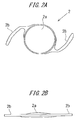
- FIGS. 2A and 2B are diagrams schematically illustrating the configuration of the intraocular lens 2.
- FIG. 2A is a plan diagram of the intraocular lens 2
- FIG. 2B is a side diagram of the intraocular lens 2.
- the intraocular lens 2 includes an optical member 2a with a predetermined power and supporting members 2b provided for the optical member 2a.
- the supporting member 2b is a member for settling the optical member 2a in the eye.
- the optical member 2a and the supporting members 2b are formed from a flexible resin material.
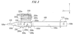
- FIG. 3 is a plane diagram of the nozzle body 100.
- the intraocular lens 2 is set on the stage member 200 of the nozzle body 100. And the intraocular lens 2 is pushed by the plunger 300 and thrust from the insertion tube 130. It is noted that a through-hole 100c is provided for the nozzle body 100.
- the cross-section shape of the through-hole 100c varies according to the change of the contour of the nozzle body 100.
- the intraocular lens 2 is thrust from the insertion tube 130, the intraocular lens 2 is deformed according to the change of the cross-section shape of the through-hole 100c of the nozzle body 100 into a shape in which the intraocular lens 2 can be easily inserted into the discission wound of the patient's eye.
- a stage groove 200a is formed on the stage member 200.
- the width of the stage groove 200a is slightly larger than the outside diameter of the optical member 2a of the intraocular lens 2.
- the dimension of the stage groove 200a in the Z axis direction is configured to be larger than the whole length of the intraocular lens 2 including the supporting members 2b which extend from the both sides of the intraocular lens 2.
- the bottom surface of the stage groove 200a forms a setting surface 200b.
- the position of the setting surface 200b in the X axis direction is set to be on the positive side of the X axis to the position of the bottom surface of the through-hole 100c of the nozzle body 100.
- the bottom surface of the through-hole 100c is a surface which is parallel to the Y-Z plane and is provided on the negative side of the X axis in the internal surface of the through-hole 100c in FIG. 3 . It is noted in the following descriptions of other members that the bottom surfaces have similar meanings.
- the setting surface 200b and the bottom surface of the through-hole 100c are connected with each other by the bottom slant surface 100d.
- the stage member 200 and the stage lid member 220 are formed as a unit.
- the dimension of the stage lid member 220 in the Z axis direction is similar to the dimension of the stage member 200.
- the stage lid member 220 is connected with the stage member 200 by a laminated connection member 230 which is formed by extending the side surface of the stage member 200 toward stage lid member 220.
- the connection member 230 is configured to fold in half and the stage lid member 220 can overlap the stage member 200 from the positive side of the X axis by folding the connection member 230.
- Ribs 220a and 220b are provided on the surface which the setting surface 200b faces when the stage lid member 220 is closed for reinforcing the stage lid member 220 and settling the intraocular lens 2 in the stage member 200.
- a guide protrusion 220c is provided as a guide of the plunger 300 when the plunger 300 is pushed toward the tip 100a of the nozzle body 100.
- the positioning member 210 is detachably provided beneath the setting surface 220b of the stage member 200, that is on the negative side of the X axis.
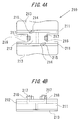
- FIGS. 4A and 4B schematically illustrate the configurations of the positioning member 210.
- FIG. 4A is a plane diagram illustrating the positioning member 210
- FIG. 4B is a side diagram thereof.
- the positioning member 210 is configured as a member separated from the nozzle body 100.
- Side wall members 211 are connected with each other by a connection member 212 to form a pair.
- a retaining member 213 extending outward is provided at the lower end of each side wall member 211.
- a pair of first settling members 214 protruding upward is formed on the upper end of each side wall member 211.
- the shape of the first settling member 214 when the member is viewed from above is arc.
- a first positioning member 215 protruding upward is formed on the side of the outer circumference of the upper end surface of the first settling member 214. The distance between internal circles of the first positioning members 215 is slightly larger than the diameter of the optical member 2a of the intraocular lens 2.
- a pair of the second settling members 216 protruding upward is formed on both ends in the front-back direction of the connecting member 212.
- the shape of the first settling member 216 when the member is viewed from above is rectangular.
- the height of the second settling member 216 is similar to the height of the upper end surface of the first settling member 214.
- a second positioning member 217 protruding upward as a whole is formed on the side of the outer circumference of the second settling member 216 from the right end to the left end of the second settling member 216.
- the distance between the second positioning members 217 is slightly larger than the diameter of the optical member 2a of the Intraocular lens 2.
- a latching protrusion 218 slightly protruding in the forward and backward direction is formed on the upper end of the second settling member 216 from the right end to the left end of the second settling member 216.
- the positioning member 210 is assembled from the underside of the setting surface 200b of the nozzle body 100, that is from the negative side of the X axis.
- Four setting surface through-holes are formed on the setting surface 200b of the nozzle body 100 to penetrating the nozzle body 100 through in the thickness direction of the nozzle body 100.
- the shape of the setting surface through-hole 200c is similar to and slightly larger than the shape of the first settling member 214 and the shape of the second settling member 216 of the positioning member 210 when the first settling member 214 and the second settling member 216 are viewed from above, that is, from the positive side of the X axis.
- the positioning member 210 when the positioning member 210 is attached to the nozzle body 100, the first settling member 214 and the second settling member 216 are inserted into the setting surface through-holes 200c from beneath the setting surface 200b to protrude upward from the setting surface 200b.
- the latching protrusion 218 provided for the second settling member 216 is protruding from the setting surface 200b through the setting surface through-hole 200c and is fixed at the position above the setting surface 200b. Therefore, the positioning member 210 is assembled from beneath the nozzle body 100, and the first settling member 214 and the second settling member 216 are fixed with protruding from the setting surface 200b.
- the bottom surface of the optical member 2a in the peripheral area of the optical member 2a is set on the upper surface of the first settling member 214 and the second settling member 216.
- the position of the optical member 2a in the Z axis direction is determined by the first positioning member 215 and the second positioning member 217.
- FIG. 5 schematically illustrates the configuration of the plunger 300.
- the length of the plunger in the Z axis direction is slightly larger than the length of the nozzle body 100.
- the plunger 300 includes an action member 310 on the fore-end side of the plunger 300, that is on the positive side of the Z axis the shape of which is cylinder and an insertion member 320 on the back-end side of the plunger 300, that is on the negative side of the Z axis the shape of which is similar to a rectangular rod.
- the action member 310 includes a cylindrical member 310a and a flattened member 310b which forms a sheet expanding in the Y axis direction from the cylindrical member 310a.
- a notch member 310c is formed at the tip of the action member 310.
- the notch member 310c is configured to be a groove which opens toward the positive side of the X axis and penetrates the action member 310 through in the Y axis direction.
- the end surface of the notch member 310c provided on the side of the tip of the action member 310 is configured to be an oblique surface which is ascending toward the positive side of the X axis as the position on the oblique surface becomes close to the tip of the action member 310.
- the cross section of the insertion member 320 as a whole is H-shaped and the dimension of the insertion member 320 in the X axis direction and the Y axis direction is slightly smaller than the dimension of the through-hole 100c of the nozzle body 100.
- the pressing plate member 330 expanding in the x-y plane the shape of which is disk is provided at the back-end of the insertion member 320.
- a notch 320a protruding toward the positive side of the X axis is formed at a part on the forward side to the center of the insertion member 320 in the Z axis direction.
- the notch 320a can be moved to ward the X axis direction due to the flexibility of the material used for the plunger 300.
- the positions where the notch 320a and the latching hole 120a are provided are determined to achieve that the tip of the action member 310 is positioned posterior to the optical member 2a of the intraocular lens 2 set on the stage member 200 and that the segment member 310c support the supporting member 2b of the optical member 2a from beneath.
- the plunger 300 is inserted into the nozzle body 100 and set in the initial position before the insertion apparatus 1 as described above is used.
- the positioningmember 210 is attached to the stage member 200 from beneath setting surface 200b as described above. Therefore, the first settling member 214 and the second settling member 216 of the positioning member 210 are fixed to protruding from the setting surface 200b.
- the intraocular lens 2 is settled on the first settling member 214 and the second settling member 216 in the state in which the supporting member 2b is positioned in the Z axis direction. In this state, since the peripheral part of the optical member is in contact with the first settling member 214 and the second settling member 216, the central part of the intraocular lens 2 is supported in an unloaded state. In addition, in this state, the supporting member 2b of the intraocular lens 2 is supported by the bottom surface of the segment member 310c of the plunger 300.
- the second settling member 216 functions as a stopper for preventing the plunger 300 from moving toward the tip 100a of the nozzle body 100. Therefore, the plunger 300 cannot move unless the positioning member 210 is detached from the nozzle body 100.
- the positioning member 210 is detached from the nozzle body 100 first.
- the first settling member 214 and the second settling member 216 supporting the optical member 2a of the intraocular lens 2 is receded from the setting surface 200b and then the intraocular lens 2 is settled on the setting surface 200b.
- the setting surface 200b is flat, the intraocular lens 2 can be securely settled on the setting surface 200b.
- the width of the stage groove 200a is configured to be slightly larger than the diameter of the optical member 2a of the intraocular lens 2, the intraocular lens 2 can be effectively prevented from rotating in its circumferential direction on the setting surface 200b.
- the insertion tube 130 of the nozzle body 100 is inserted into the eye from the discission wound of the eye.
- the pressing plate member 330 of the plunger 300 is pressed toward the tip 100a of the nozzle body 100.
- the tip of the action member 310 of the plunger 300 comes into contact with the circumference part of the optical member 2b of the intraocular lens 2 settled on the setting surface 200a, and then the intraocular lens 2 is guided toward the insertion tube 130 by the plunger 300.
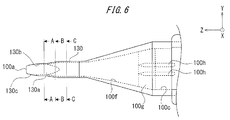
- FIG. 6 is a plane diagram illustrating the details of the part around the insertion tube 130 of the nozzle body 100.
- the contour of the nozzle body 100 is tapering from the stage member 200 toward the tip of the nozzle body 100.
- a diameter-reducing part 100f is provided for the through-hole 100c.
- the diameter-reducing part 100f is configured to achieve that the dimension of the bottom surface and the upper surface becomes smaller as the position on the diameter-reducing part 100f becomes closer to the tip 100a. Therefore, the cross-section of the diameter-reducing part 100f becomes also smaller along with the dimension of the bottom surface and the upper surface.
- the thickness of the wall of the diameter-reducing part 100f is set to achieve that the diameter-reducing part 100f is not folded when the insertion apparatus 1 is used. It is noted that the bottom surface at the back end of the diameter-reducing part 100f is formed as an oblique surface 100g which rises up toward the positive side of the X axis as the position on the diameter-reducing part 100f becomes closer to the tip 100a.
- the oblique surface 100g functions an uneven surface.
- a pair of introduction protrusions 100h which extends in the Z axis direction of the nozzle body 100 at the bottom surface of the through-hole 100c is formed near the diameter-reducing part 100f.
- Each introduction protrusion 100h faces each other across the center of the bottom surface of the through-hole 100c.
- the introduction protrusion 100h runs from before backward on the oblique surface 100.
- the introduction protrusions 100h are formed to protrude upward slightly from the bottom surface of the diameter-reducing part 100f and extend in parallel to each other.
- the height of the introduction protrusion 100h is the same as the height of the oblique surface 100g since the oblique surface 100g rises up as the position on the diameter-reducing part 100f becomes closer to the tip 100a.
- the distance between the introduction protrusions 100h is slightly larger than the width of the action member 310 of the plunger 300.
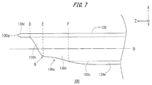
- the through-hole 100c is formed to extend in a linear arrangement with the almost the same cross section in the insertion tube 130 as illustrated in FIG. 7 .
- the through-hole 100c functions as a fore-end opening 130a of the insertion tube 130.
- a fore-end area 130b is provided for the fore-end side of the fore-end opening 130a.
- a planate protrusion 130c is provided for the fore-endarea 130b.
- the planate protrusion 130c is formed to extend the direction toward which the plunger 300 is pushed in the nozzle body 100, that is the direction of the movement of the intraocular lens 2 (Z axis direction in FIG. 7 ).
- the fore-end opening 130a is formed by a plane which descends toward the negative side of the Z axis as the position on the insertion tube 130 moves toward the negative side of the X axis.
- the upper side of the insertion tube 130 is formed to be longer in the Z axis direction than the lower side of the insertion tube 130.
- the fore-end opening 130a is configured to have an inflection point G at which the curvature of the contour of the fore-end opening 130a changes more dynamically than the curvatures at the other points of the fore-end opening 130a.
- the side of the fore-end opening 130a closer to the tip 100a than the inflection point G is referred to as the fore-end area 130b of the fore-end opening 130a and the side of the fore-end opening 130a closer to the back-end 100b than the inflection point G is referred to as the back-end area 130d of the fore-end opening 130a.
- the central axis O is defined in the direction which is parallel to the Z axis of the nozzle body 100.
- the fore-end opening 130a includes the fore-end area 130b and the back-end area 130d.
- the end surface of the fore-end opening 130a is the oblique surface oblique to the plane which is perpendicular to the central axis O.
- the angle of gradient of the oblique surface in the fore-end area 130b to the plane which is perpendicular to the central axis O is smaller than the angle of gradient of the oblique surface in the back-end area 130d to the plane which is perpendicular to the central axis O.
- the side wall in the fore-end area 130b rises in the X axis direction in the lateral diagram of the fore-end opening 130a.
- the back-end area 130d is connected with the body member 130e while the height of the side wall in the fore-end area 130b progressively increases in the X axis direction.
- the side wall in the fore-end area 130b extends in the direction of the optical axis, that is the X axis direction in FIG. 7 , of the intraocular lens 2 settled on the stage member 210.
- the direction which the side wall in the fore-end area 130b extends that is the X axis direction in FIG. 7 is perpendicular to the direction toward which the plunger 300 is pushed in the nozzle body 100, the direction toward which the intraocular lens 2 moves in the nozzle body 100 and the direction toward which the protrusion 130c extends.
- the contour of the fore-end opening 130a is a shape which is tapering toward the tip 100a. It is noted that although the contour of the fore-end opening 130a in the fore-end area 130b is not a taper in the present embodiment, the contour of the fore-end opening 130a can be configured to be a which is tapering from the back-end area 130d to the fore-end area 130b. With configuration in which the contour of the fore-end opening 130a is tapering, the fore-end opening can be more easily inserted into the discission wound the width of which is smaller than conventional discission wounds.
- the contour of the nozzle body 100 includes a tapering part 100i which is tapering toward the tip 100a of the nozzle body 100.
- the fore-end opening 130a of the insertion tube 130 of the nozzle body 100 includes an opening which opens toward the negative side of the X axis.
- the insertion tube 130 includes the body member 130e, the back-end area 130d, the fore-end area 130b and the protrusion 130c in this order from the back end 100b to the tip 100a of the nozzle body 100. Additionally, when the insertion tube 130 is divided into portions by planes perpendicular to the Z axis as illustrated in FIG.
- the part from the plane F to the back end 100b is referred to as the body member 130e
- the part from the plane E to the plane F is referred to as the back-end area 130d
- the part from the plane D to the plane E is referred to as the fore-end area 130c
- the part from the plane D to the tip 100a is referred to as the protrusion 130c.
- the body member 130e is a tube member. As illustrated in FIG. 7 , the thickness on the bottom side of the body member 130e progressively decreases as the position on the body member 130e is closer to the tip 100a.
- the body member 130e and the back-end area 130d are smoothly connected with each other at the position indicated by the plane F.
- the cross-section of the back-end area 130d with respect to the XY plane is configured to be smaller and the contour is a taper.
- the height of the side wall in the back-end area 130d in the X axis direction progressively decreases. Therefore, the back-end area 130d is smoothly connected with the body member 130e and the fore-end area 130b.
- the fore-end area 130b is configured to have an upper surface which is almost parallel to the YZ plane and a lateral wall which is perpendicular to the upper surface and is almost parallel to the XZ plane.
- the upper surface in the fore-end area 130b is connected with the protrusion 130c on the side of the tip 100a.
- FIG. 7 illustrates that the height of the lateral wall in the fore-end area 130b in the X axis direction rapidly increases from the plane D to the plane E. Since the lateral wall in the fore-end area 130b is configured to be elevated just after the protrusion 130c, the intraocular lens 2 can be stably retained and guided into the human crystalline capsule.
- the protrusion 130c is a planate member which is almost parallel to the YZ plane.
- the protrusion 130c is configured by extending the upper surface of the fore-end area 130b toward the tip 100a.
- FIG. 9 illustrates three cross-sections of the insertion tube 130 of the nozzle body 100.
- FIG. 9A is a sectional diagram taken along A-A of FIG. 6
- FIG. 9B is a sectional diagram taken along B-B of FIG. 6
- FIG. 9C is a sectional diagram taken along C-C of FIG. 6 .
- FIGS. 9A to 9C illustrate cross-sections of the insertion tube 130 when the insertion tube 130 is viewed from the negative side of the Z axis to the positive side of the Z axis, that is from the back end 100b of the nozzle body 100 to the tip 100a of the nozzle body 100.
- the fore-end area 130b of the fore-end opening 130a in the cross section thereof is configured by providing a pair of lateral walls which are parallel to the XZ plane and an upper surface which are parallel to the YZ plane and connecting the pair of lateral walls and the upper surface with each other smoothly.
- the back-end area 130d of the fore-end opening 130a in the cross section thereof is configured by changing the planate lateral wall of the fore-end area 130b into a curved lateral wall. Further, as illustrated in FIG.
- the body member 130e in the cross section thereof is configured by providing the upper surface and the lateral wall in the back-end area 130d and a lower surface which faces the upper surface across the central axis O. Moreover, the upper surface, the lower surface and the pair of lateral walls encloses the through-hole 100c.
- the intraocular lens 2 moves through the tapering part 100i and the body member 130e of the insertion tube 130 and reach the fore-end opening 130a.
- the intraocular lens 2 moves through the back-end area 130d to the fore-end area 130b, and further moves to the human crystalline capsule with retained by the lateral walls in the fore-end area 130b. Therefore, the intraocular lens 2 can be prevented from going out from the eye when the intraocular lens 2 is moved to the fore-end opening 130a for guiding the intraocular lens 2 into the human crystalline capsule.
- the intraocular lens 2 can be stably retained and guided into the human crystalline capsule after the insertion tube 130 is inserted into the eye until the insertion tube 130 reaches a predetermined position. And with the configuration as described above, the intraocular lens 2 can be prevented from going out of the eye without the operator's intention.
- the insertion tube 130 can be more easily inserted into a discission wound than conventional insertion tubes and the intraocular lens 2 canbemore stably retained and guided into the human crystalline capsule than conventional insertion tubes.
- the insertion apparatus 1 is configured to achieve that the length of the protrusion 130c in the Z axis direction is about 1.0 mm, the width of the protrusion 130c in the Y axis direction is from about 1.1 mm to about 1.6 mm, the length of the fore-end area 130b in the Z axis direction is about 1.0 mm, the length of the back-end area 130d is about 1. 5 mm, and the width of the insertion tube 130 in the Y axis direction is from about 1.6 mm to about 2.4 mm.
- the insertion apparatus 1 can be more easily inserted into a discission wound than conventional insertion apparatuses and the Intraocular lens can be more stably retained and guided into the human crystalline capsule than conventional insertion apparatuses.
- the fore-end opening 130a is configured to have the inflection point G in the side diagram of the insertion tube 130.
- another inflection point can be provided for the fore-end area 130b and/or the back-end area 130d.
- the contours of the fore-end area 130b and the back-end area 130d can be configured sorely with curves or with combination of linear lines.
- the protrusion 130c is a planate member which is almost parallel to the YZ plane in the above descriptions, the protrusion 130c can be a member which is, for example, curved in an arc in the cross section by the XY plane.
- the lateral walls which forms the fore-end area 130b is a pair of lateral walls which is almost parallel to the XZ plane, the lateral walls can be walls which are, for example, curved in an arc in the cross section by the XY plane.
- the lateral walls can be configured to achieve that the cross section of the lateral walls by the XY plane becomes a V shape or an inverted V shape as long as the lateral walls can retain the intraocular lens.
- a variation of the insertion apparatus according to the above embodiment is described below.
- An fore-end opening, protrusion, an oblique surface, fore-end area and the like the configurations of which are similar to those in the above embodiment are provided for the insertion apparatus according to the variation. Therefore, when the insertion apparatus according to the variation can also be more easily inserted into a discission wound than conventional insertion apparatuses and the intraocular lens can be more stably retained and guided into the human crystalline capsule than conventional insertion apparatuses.
- the contour of the nozzle body of the insertion apparatus is modified within the technical scope of the above embodiment.
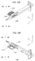
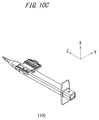
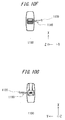
- a needle hole 1200 into which a tip of a needle of a syringe filled with viscoelastic material is inserted and a guide wall 1110 for guiding the tip of the needle of the syringe to the needle hole 1200 are provided for the stage lid member 1120 of the nozzle body 1100 as illustrated in FIG. 10 .
- a three-piece intraocular lens 1002 is set instead of the one-piece intraocular lens 2 of the above embodiment.
- the fore-end side of the nozzle body 1100 is configured similar to the fore-end side of the nozzle body 100 as described above, the modifications of the configurations of the insertion apparatus in the present variation still achieve the effect achieved by the insertion apparatus according to the above embodiment.
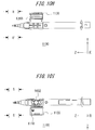
- FIGS. 10A to 10C are perspective diagrams illustrating the nozzle body 1100 of the insertion apparatus according to the variation.
- FIG. 10D is a diagram of the nozzle body 1100 when the nozzle body 1100 is viewed in the direction from the negative side of the Y axis to the positive side of the Y axis.
- FIG. 10E is a diagram of the nozzle body 1100 when the nozzle body 1100 is viewed in the direction from the positive side of the X axis to the negative side of the X axis.
- FIG. 10F is a diagram of the nozzle body 1100 when the nozzle body 1100 is viewed in the direction from the negative side of the Z axis to the positive side of the Z axis.
- FIG. 10D is a diagram of the nozzle body 1100 when the nozzle body 1100 is viewed in the direction from the negative side of the Y axis to the positive side of the Y axis.
- FIG. 10E is a diagram of the nozzle
- FIG. 10G is a diagram of the nozzle body 1100 when the nozzle body 1100 is viewed in the direction from the positive side of the Z axis to the negative side of the Z axis.
- FIG. 10H is a diagram of the nozzle body 1100 when the nozzle body 1100 is viewed in the direction from the positive side of the X axis to the negative side of the X axis.
- FIG. 10I is a diagram of the nozzle body 1100 when the nozzle body 1100 is viewed in the direction from the negative side of the X axis to the positive side of the X axis.
- FIG. 10J is a partial enlarged diagram illustrating the area of the nozzle body 1100 indicated by "N” and “N'” in FIG. 10A .
- FIG. 10K is a partial enlarged diagram illustrating the area of the nozzle body 1100 indicated by “P” and “P'” in FIG. 10B .
- FIG. 10L is a partial enlarged diagram illustrating the area of the nozzle body 1100 indicated by “Q” and “Q'” in FIG. 10D .
- FIG. 10M is a partial enlarged diagram illustrating the area of the nozzle body 1100 indicated by “R” and “R'” in FIG. 10H .
- FIG. 10N is a partial enlarged diagram illustrating the area of the nozzle body 1100 indicated by "S” and “S'” in FIG. 10I .
- FIG. 10P is a cross-section diagram of the nozzle body 1100 taken along T-T of FIG. 10L .
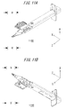
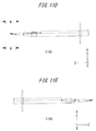
- FIGS. 11A to 11C are perspective diagrams illustrating the nozzle body of the insertion apparatus according to the variation.
- FIG. 11D is a diagram of the nozzle body 1100 when the nozzle body 1100 is viewed in the direction from the negative side of the Y axis to the positive side of the Y axis.
- FIG. 11E is a diagram of the nozzle body 1100 when the nozzle body 1100 is viewed in the direction from the positive side of the X axis to the negative side of the X axis.
- FIG. 11G is a diagram of the nozzle body 1100 when the nozzle body 1100 is viewed in the direction from the positive side of the Z axis to the negative side of the Z axis.
- FIG. 11D is a diagram of the nozzle body 1100 when the nozzle body 1100 is viewed in the direction from the negative side of the Y axis to the positive side of the Y axis.
- FIG. 11E is a diagram of the nozzle body 1
- FIG. 11H is a diagram of the nozzle body 1100 when the nozzle body 1100 is viewed in the direction from the positive side of the X axis to the negative side of the X axis.
- FIG. 11I is a diagram of the nozzle body 1100 when the nozzle body 1100 is viewed in the direction from the negative side of the X axis to the positive side of the X axis.
- FIG. 11J is a partial enlarged diagram illustrating the area of the nozzle body 1100 indicated by “U” and “U'” in FIG. 11A .
- FIG. 11K is a partial enlarged diagram illustrating the area of the nozzle body 1100 indicated by “V” and “V'” in FIG. 11B .
- FIG. 11L is a partial enlarged diagram illustrating the area of the nozzle body 1100 indicated by “W” and “W' “ in FIG. 11D .
- FIG. 11M is a partial enlarged diagram illustrating the area of the nozzle body 1100 indicated by "X” and “X'” in FIG. 11H .
- FIG. 11N is a partial enlarged diagram illustrating the area of the nozzle body 1100 indicated by "Y” and “Y'” in FIG. 11I .
- FIG. 11P is a cross-section diagram of the nozzle body 1100 taken along Z-Z of FIG. 11L .
Landscapes
- Health & Medical Sciences (AREA)
- Ophthalmology & Optometry (AREA)
- Cardiology (AREA)
- Oral & Maxillofacial Surgery (AREA)
- Transplantation (AREA)
- Engineering & Computer Science (AREA)
- Biomedical Technology (AREA)
- Heart & Thoracic Surgery (AREA)
- Vascular Medicine (AREA)
- Life Sciences & Earth Sciences (AREA)
- Animal Behavior & Ethology (AREA)
- General Health & Medical Sciences (AREA)
- Public Health (AREA)
- Veterinary Medicine (AREA)
- Prostheses (AREA)
Abstract
Description
- The embodiments discussed herein pertain to an intraocular lens insertion apparatus.
- Intraocular lenses are widely used to be replaced with human opacity crystalline lenses in cataract treatments ornormal human crystalline lenses for compensating the optical powers of the lenses. In intraocular lens insertion surgeries for the cataract treatments, a discission wound which is several millimeters in length is produced at the edge of the cornea, the human crystalline lens is crushed and removed by phacoemulsification and aspiration etc. and the intraocular lens is inserted and fixed in the eye, for example.
- Polymethyl methacrylate (PMMA), acrylic resin, silicon resin etc. are used as the material of the intraocular lens. The structure of the intraocular lens can be divided into an optical member and a supporting member. The intraocular lens is enclosed in a dedicated intraocular lens insertion apparatus. When the intraocular lens is used, the intraocular lens insertion apparatus is taken out from the package of the apparatus in an asepticmanner, and the tip of the insertion apparatus is inserted into the eye from the discission wound and the insertion apparatus is handled to guide the intraocular lens into the human crystalline lens capsule.
- It is desirable that the discission wound be as small as possible in order to mitigate the burden of the patient. Therefore, the insertion apparatus is configured to eject the intraocular lens into the eye in a folded state.
- For example,
patent document 1 discloses a structure in which the opening of the tip of the insertion apparatus is configured to have an oblique surface oblique to the longitudinal direction of the opening. In addition, a roof is provided for the tip of the opening. The roof functions to open the wound when the tip of the insertion apparatus is inserted into the wound. Further,patent document 2 discloses a structure in which the end surface of the opening of the tip of the insertion apparatus is formed in a curved shape. Therefore, the possibility that the insertion apparatus unnecessarily stimulates the eye tissues can be reduced since the opening in the curved shape can make a smooth contact with the wound etc. when the tip of the insertion apparatus is inserted into the wound. -
- [PTL 1]
Japanese Patent Application Laid-Open Publication No.2008-307376 - [PTL 2]
Japanese Patent Application Laid-Open Publication No.2009-160153 - However, when the discission wound becomes smaller, the insertion apparatus with the opening having the shape as described in the above patent documents may face a difficulty in insert the opening into a predetermined position in the discission wound. In addition, when the opening is not completely inserted into the discission wound and the insertion apparatus is handled to eject the Intraocular lens into the human crystalline lens capsule, the intraocular lens may go out from a part of the opening which is located outside of the discission wound and then the intraocular lens cannot be inserted into the eye.
- One aspect of the present invention lies in providing an insertion apparatus which prevents an intraocular lens from going out to the outside of the eye and ensures a secure insertion of the intraocular lens into the eye when the insertion apparatus is inserted a discission wound which is smaller than that of conventional discission wounds.
- According to an embodiment, it is provided an intraocular lens insertion apparatus, including a cylindrical body member configured to retain an intraocular lens, a fore-end opening provided for a tip of the body member, and a planate protrusion provided for a tip of the fore-end opening, wherein an end surface of the fore-end opening is an oblique surface which is oblique to a plane perpendicular to a central axis of the body member, and a fore-end area including a pair of lateral walls which are parallel to each other across the central axis is formed on a side of the tip of the fore-end opening. Therefore, the insertion apparatus can be inserted into a discission wound smaller than conventional discission wounds, can prevent the intraocular lens from going out of the eye from the insertion apparatus and can stably retain and guide the intraocular lens into the human crystalline capsule.
- In addition, the intraocular lens insertion apparatus can be configured to achieve that a back-end area which is connected with a back end of the fore-end area is formed on a side of a back end of the fore-end opening, and an angle of gradient of an oblique surface in the fore-end area to a plane perpendicular to the central axis is smaller than an angle of gradient of an oblique surface in the back-end area to a plane perpendicular to the central axis. Further, the contour of the fore-end opening in a side view can include an inflection point between the fore-end area and the back-end area. With such configurations, the lateral walls in the fore-end area in the side view are configured to rise at a steep angle and therefore the intraocular lens can be more stably retained by the lateral walls than the conventional insertion apparatus. Therefore, the intraocular lens can be prevented from going out of the eye from the fore-end opening when the intraocular lens is guided into the human crystalline capsule.
- Further, the intraocular lens insertion apparatus can be configured to achieve that the shape of the fore-end opening is tapering toward the tip of the fore-end opening. Therefore, the tip of the fore-end opening can be more easily inserted into the eye than conventional insertion apparatuses after the insertion apparatus is inserted into the small discission wound. In addition, the body member can include a positioning member for positioning the intraocular lens, and the intraocular lens can be positioned by the positioning member in the body member in advance.
- According to an embodiment, an insertion apparatus which prevents an intraocular lens from going out to the outside of the eye and ensures a secure insertion of the intraocular lens into the eye when the insertion apparatus is inserted a discission wound which is smaller than that of a conventional discission wound can be achieved.
-
-
FIGS. 1A and 1B are diagrams schematically illustrating an intraocular lens insertion apparatus according to an embodiment; -
FIGS. 2A and 2B are diagrams schematically illustrating an intraocular lens according to an embodiment; -
FIG. 3 is a diagram schematically illustrating a nozzle body of an intraocular lens insertion apparatus according to an embodiment; -
FIG. 4 is a diagram schematically illustrating a positioning member of an intraocular lens insertion apparatus according to an embodiment; -
FIGS. 5A and 5B are diagrams schematically illustrating a plunger for an intraocular lens according to an embodiment; -
FIG. 6 is a plan detail diagram illustrating a tip of an intraocular lens insertion apparatus according to an embodiment; -
FIG. 7 is a side detail diagram illustrating a tip of an intraocular lens insertion apparatus according to an embodiment; -
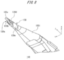
FIG. 8 is a perspective diagram illustrating a tip of an intraocular lens insertion apparatus according to an embodiment; -
FIGS. 9A to 9C are cross-section diagrams illustrating a insertion tube of an intraocular lens insertion apparatus according to an embodiment; -
FIG. 10A is a perspective diagram illustrating a nozzle body of an intraocular lens insertion apparatus according to a variation example; -
FIG. 10B is a perspective diagram illustrating a nozzle body of an intraocular lens insertion apparatus according to a variation example; -
FIG. 10C is a perspective diagram illustrating a nozzle body of an intraocular lens insertion apparatus according to a variation example; -
FIG. 10D is a diagram illustrating a nozzle body of an intraocular lens insertion apparatus according to a variation example; -
FIG. 10E is a diagram illustrating a nozzle body of an intraocular lens insertion apparatus according to a variation example; -
FIG. 10F is a diagram illustrating a nozzle body of an intraocular lens insertion apparatus according to a variation example; -
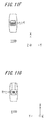
FIG. 10G is a diagram illustrating a nozzle body of an intraocular lens insertion apparatus according to a variation example; -
FIG. 10H is a diagram illustrating a nozzle body of an intraocular lens insertion apparatus according to a variation example; -
FIG. 10I is a diagram illustrating a nozzle body of an Intraocular lens insertion apparatus according to a variation example; -
FIG. 10J is a partial enlarged diagram illustrating a nozzle body of an intraocular lens insertion apparatus according to a variation example; -
FIG. 10K is a partial enlarged diagram illustrating a nozzle body of an intraocular lens insertion apparatus according to a variation example; -
FIG. 10L is a partial enlarged diagram illustrating a nozzle body of an intraocular lens insertion apparatus according to a variation example; -
FIG. 10M is a partial enlarged diagram illustrating a nozzle body of an intraocular lens insertion apparatus according to a variation example; -
FIG. 10N is a partial enlarged diagram illustrating a nozzle body of an intraocular lens insertion apparatus according to a variation example; -
FIG. 10P is a cross-section diagram illustrating a nozzle body of an intraocular lens insertion apparatus according to a variation example; -
FIG. 11A is a perspective diagram illustrating a nozzle body of an intraocular lens insertion apparatus according to a variation example; -
FIG. 11B is a perspective diagram illustrating a nozzle body of an intraocular lens insertion apparatus according to a variation example; -
FIG. 11C is a perspective diagram illustrating a nozzle body of an intraocular lens insertion apparatus according to a variation example; -
FIG. 11D is a diagram illustrating a nozzle body of an intraocular lens insertion apparatus according to a variation example; -
FIG. 11E is a diagram illustrating a nozzle body of an intraocular lens insertion apparatus according to a variation example; -
FIG. 11F is a diagram illustrating a nozzle body of an intraocular lens insertion apparatus according to a variation example; -
FIG. 11G is a diagram illustrating a nozzle body of an intraocular lens insertion apparatus according to a variation example; -
FIG. 11H is a diagram illustrating a nozzle body of an intraocular lens insertion apparatus according to a variation example; -
FIG. 11I is a diagram illustrating a nozzle body of an intraocular lens insertion apparatus according to a variation example; -
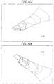
FIG. 11J is a partial enlarged diagram illustrating a nozzle body of an intraocular lens insertion apparatus according to a variation example; -
FIG. 11K is a partial enlarged diagram illustrating a nozzle body of an intraocular lens insertion apparatus according to a variation example; -
FIG. 11L is a partial enlarged diagram illustrating a nozzle body of an intraocular lens insertion apparatus according to a variation example; -
FIG. 11M is a partial enlarged diagram illustrating a nozzle body of an intraocular lens insertion apparatus according to a variation example; -
FIG. 11N is a partial enlarged diagram illustrating a nozzle body of an intraocular lens insertion apparatus according to a variation example; and -
FIG. 11P is a cross-section diagram illustrating a nozzle body of an intraocular lens insertion apparatus according to a variation example. - First, an intraocular lens insertion apparatus according to one embodiment is described below with reference to the drawings. However, it is to be understood that the following descriptions are exemplary and explanatory for the intraocular lens insertion apparatus, and are not restrictive of the invention, as claimed.
- As illustrated in
FIGS. 1A and 1B , the intraocularlens insertion apparatus 1 according to the first embodiment includes anozzle body 100, astage member 200 and aplunger 300. Thenozzle body 100 is formed into a shape similar to an elongated tube and a hollow space is provided over the entire length of thenozzle body 100. It is noted that thenozzle body 100 corresponds to an example of the body of the intraocular lens insertion apparatus. The cross-section of thenozzle body 100 formed by a surface which is vertical to the longitudinal direction of thenozzle body 100 is approximately rectangular. Further, anintraocular lens 2 is retained in thenozzle body 100 by the stage member. Theplunger 300 is a bar member which is elongated tube in shape. Theplunger 300 is partially inserted into the tube portion of thenozzle body 100. Theplunger 300 is used as a push member used for guiding theintraocular lens 2 into the human crystalline lens capsule. - As illustrated in
FIGS. 1A and 1B , the Z axis is set so that the direction of the Z axis is parallel to the longitude direction of theinsertion apparatus 1 and the direction of the Z axis going from the back end to the front end of thenozzle body 100 is the positive direction. And the X axis and the Y axis are set to bisect each other at right angles and to be perpendicular to the Z axis. As described below, the X axis corresponds to the optic axis of theintraocular lens 2 which is set by the positioningmember 210 in thenozzle body 100. In addition, the Z axis is parallel to the direction in which theplunger 300 inserted into thenozzle body 100 is pushed. It is noted in the following descriptions of each member that a surface provided in the negative side of the X axis is referred to as a bottom surface and that a surface provided in the positive side of the X axis is referred to an upper surface in some cases. Moreover, it is also noted that the positive side of the X axis, the negative side of the X axis, the positive side of the Z axis and the negative side of the Z axis are referred to as an upward direction, a downward direction, a forward direction and a backward direction, respectively in some cases. - A holding
member 110 which is planate in shape is provided near theback end 100b of thenozzle body 100 to protrude from thenozzle body 100 in the X axis direction and Y axis direction. The user of the insertion apparatus places a finger on the holdingmember 110 when the user pushes theplunger 300 toward thetip 100a of thenozzle body 100. In addition, a latchinghole 120 is provided for thenozzle body 100 on the side of theback end 100b to the holdingmember 110. The latchinghole 120 is used as retaining member for retaining theplunger 300 in thenozzle body 100. When a protruding member which protrudes from theplunger 300 in the positive direction of the X axis engage with the latchinghole 120 with theplunger 300 inserted into thenozzle body 100, the relative position of theplunger 300 to thenozzle body 100 is fixed. When the user pushes theplunger 300 toward thetip 100a of thenozzle body 100, the protruding member of theplunger 300 moves toward thetip 100a of thenozzle body 100 to be released from the engagement with the latchinghole 120. - Further, a
stage member 200 is provided near thetip 100a of thenozzle body 100. Thestage member 200 includes apositioning member 210 and astage lid member 220. The positioningmember 210 is a member for settling theintraocular lens 2 on thestage member 200 while theinsertion apparatus 1 is being transported and before the insertion apparatus is used. When theinsertion apparatus 1 is manufactured, thestage lid member 220 is opened and theintraocular lens 2 is set on thestage member 200 with the positioningmember 210 attached to thestage member 200. And then, the user detaches thepositioning member 210 from thestage member 200 with thestage lid member 220 closed. And, the user move theplunger 300 toward thetip 100a of thenozzle body 100 to thrust theintraocular lens 2 from theinsertion tube 130 while theintraocular lens 2 is pushed by theplunger 300. It is noted that thenozzle body 100, thestage member 200 and theplunger 300 is formed from resin such aspolypropylene. Polypropylene has been proven as a material used for medical apparatuses. In addition, polypropylene demonstrates an advantageous biocompatibility and is reliable in chemical resistance etc. -
FIGS. 2A and 2B are diagrams schematically illustrating the configuration of theintraocular lens 2.FIG. 2A is a plan diagram of theintraocular lens 2, andFIG. 2B is a side diagram of theintraocular lens 2. Theintraocular lens 2 includes anoptical member 2a with a predetermined power and supportingmembers 2b provided for theoptical member 2a. The supportingmember 2b is a member for settling theoptical member 2a in the eye. Theoptical member 2a and the supportingmembers 2b are formed from a flexible resin material. -
FIG. 3 is a plane diagram of thenozzle body 100. Theintraocular lens 2 is set on thestage member 200 of thenozzle body 100. And theintraocular lens 2 is pushed by theplunger 300 and thrust from theinsertion tube 130. It is noted that a through-hole 100c is provided for thenozzle body 100. The cross-section shape of the through-hole 100c varies according to the change of the contour of thenozzle body 100. When theintraocular lens 2 is thrust from theinsertion tube 130, theintraocular lens 2 is deformed according to the change of the cross-section shape of the through-hole 100c of thenozzle body 100 into a shape in which theintraocular lens 2 can be easily inserted into the discission wound of the patient's eye. - A
stage groove 200a is formed on thestage member 200. The width of thestage groove 200a is slightly larger than the outside diameter of theoptical member 2a of theintraocular lens 2. The dimension of thestage groove 200a in the Z axis direction is configured to be larger than the whole length of theintraocular lens 2 including the supportingmembers 2b which extend from the both sides of theintraocular lens 2. In addition, the bottom surface of thestage groove 200a forms asetting surface 200b. The position of the settingsurface 200b in the X axis direction is set to be on the positive side of the X axis to the position of the bottom surface of the through-hole 100c of thenozzle body 100. It is assumed here that the bottom surface of the through-hole 100c is a surface which is parallel to the Y-Z plane and is provided on the negative side of the X axis in the internal surface of the through-hole 100c inFIG. 3 . It is noted in the following descriptions of other members that the bottom surfaces have similar meanings. The settingsurface 200b and the bottom surface of the through-hole 100c are connected with each other by thebottom slant surface 100d. - The
stage member 200 and thestage lid member 220 are formed as a unit. The dimension of thestage lid member 220 in the Z axis direction is similar to the dimension of thestage member 200. Thestage lid member 220 is connected with thestage member 200 by alaminated connection member 230 which is formed by extending the side surface of thestage member 200 towardstage lid member 220. Theconnection member 230 is configured to fold in half and thestage lid member 220 can overlap thestage member 200 from the positive side of the X axis by folding theconnection member 230. -
Ribs setting surface 200b faces when thestage lid member 220 is closed for reinforcing thestage lid member 220 and settling theintraocular lens 2 in thestage member 200. In addition, aguide protrusion 220c is provided as a guide of theplunger 300 when theplunger 300 is pushed toward thetip 100a of thenozzle body 100. - The positioning
member 210 is detachably provided beneath the settingsurface 220b of thestage member 200, that is on the negative side of the X axis.FIGS. 4A and 4B schematically illustrate the configurations of thepositioning member 210.FIG. 4A is a plane diagram illustrating thepositioning member 210, andFIG. 4B is a side diagram thereof. The positioningmember 210 is configured as a member separated from thenozzle body 100.Side wall members 211 are connected with each other by aconnection member 212 to form a pair. A retainingmember 213 extending outward is provided at the lower end of eachside wall member 211. - A pair of first settling
members 214 protruding upward is formed on the upper end of eachside wall member 211. The shape of thefirst settling member 214 when the member is viewed from above is arc. In addition, afirst positioning member 215 protruding upward is formed on the side of the outer circumference of the upper end surface of thefirst settling member 214. The distance between internal circles of thefirst positioning members 215 is slightly larger than the diameter of theoptical member 2a of theintraocular lens 2. - In addition, a pair of the
second settling members 216 protruding upward is formed on both ends in the front-back direction of the connectingmember 212. The shape of thefirst settling member 216 when the member is viewed from above is rectangular. The height of thesecond settling member 216 is similar to the height of the upper end surface of thefirst settling member 214. Further, asecond positioning member 217 protruding upward as a whole is formed on the side of the outer circumference of thesecond settling member 216 from the right end to the left end of thesecond settling member 216. The distance between thesecond positioning members 217 is slightly larger than the diameter of theoptical member 2a of theIntraocular lens 2. Moreover, as illustrated inFIG. 4B , a latchingprotrusion 218 slightly protruding in the forward and backward direction is formed on the upper end of thesecond settling member 216 from the right end to the left end of thesecond settling member 216. - In the present embodiment, the positioning
member 210 is assembled from the underside of the settingsurface 200b of thenozzle body 100, that is from the negative side of the X axis. Four setting surface through-holes are formed on thesetting surface 200b of thenozzle body 100 to penetrating thenozzle body 100 through in the thickness direction of thenozzle body 100. The shape of the setting surface through-hole 200c is similar to and slightly larger than the shape of thefirst settling member 214 and the shape of thesecond settling member 216 of thepositioning member 210 when thefirst settling member 214 and thesecond settling member 216 are viewed from above, that is, from the positive side of the X axis. Further, when thepositioning member 210 is attached to thenozzle body 100, thefirst settling member 214 and thesecond settling member 216 are inserted into the setting surface through-holes 200c from beneath the settingsurface 200b to protrude upward from the settingsurface 200b. - Moreover, the latching
protrusion 218 provided for thesecond settling member 216 is protruding from the settingsurface 200b through the setting surface through-hole 200c and is fixed at the position above the settingsurface 200b. Therefore, the positioningmember 210 is assembled from beneath thenozzle body 100, and thefirst settling member 214 and thesecond settling member 216 are fixed with protruding from the settingsurface 200b. When theintraocular lens 2 is set on thesetting surface 200b, the bottom surface of theoptical member 2a in the peripheral area of theoptical member 2a is set on the upper surface of thefirst settling member 214 and thesecond settling member 216. In addition, the position of theoptical member 2a in the Z axis direction is determined by thefirst positioning member 215 and thesecond positioning member 217. -
FIG. 5 schematically illustrates the configuration of theplunger 300. The length of the plunger in the Z axis direction is slightly larger than the length of thenozzle body 100. Theplunger 300 includes anaction member 310 on the fore-end side of theplunger 300, that is on the positive side of the Z axis the shape of which is cylinder and aninsertion member 320 on the back-end side of theplunger 300, that is on the negative side of the Z axis the shape of which is similar to a rectangular rod. Theaction member 310 includes acylindrical member 310a and a flattenedmember 310b which forms a sheet expanding in the Y axis direction from thecylindrical member 310a. - A
notch member 310c is formed at the tip of theaction member 310. As illustrated inFIGS. 5A and 5B , thenotch member 310c is configured to be a groove which opens toward the positive side of the X axis and penetrates theaction member 310 through in the Y axis direction. Further, as illustrated inFIG. 5B , the end surface of thenotch member 310c provided on the side of the tip of theaction member 310 is configured to be an oblique surface which is ascending toward the positive side of the X axis as the position on the oblique surface becomes close to the tip of theaction member 310. - On the other hand, the cross section of the
insertion member 320 as a whole is H-shaped and the dimension of theinsertion member 320 in the X axis direction and the Y axis direction is slightly smaller than the dimension of the through-hole 100c of thenozzle body 100. In addition, thepressing plate member 330 expanding in the x-y plane the shape of which is disk is provided at the back-end of theinsertion member 320. - A
notch 320a protruding toward the positive side of the X axis is formed at a part on the forward side to the center of theinsertion member 320 in the Z axis direction. Thenotch 320a can be moved to ward the X axis direction due to the flexibility of the material used for theplunger 300. When theplunger 300 is inserted into thenozzle body 100, thenotch 320a is engaged with thelatching hole 120a which is formed on the upper surface of the nozzle body and penetrates in the thickness direction of thenozzle body 100. And then, the relative position of thenozzle body 100 and theplunger 300 in their default positions is determined. It is noted that the positions where thenotch 320a and thelatching hole 120a are provided are determined to achieve that the tip of theaction member 310 is positioned posterior to theoptical member 2a of theintraocular lens 2 set on thestage member 200 and that thesegment member 310c support the supportingmember 2b of theoptical member 2a from beneath. - The
plunger 300 is inserted into thenozzle body 100 and set in the initial position before theinsertion apparatus 1 as described above is used. In addition, thepositioningmember 210 is attached to thestage member 200 from beneath settingsurface 200b as described above. Therefore, thefirst settling member 214 and thesecond settling member 216 of thepositioning member 210 are fixed to protruding from the settingsurface 200b. - Further, the
intraocular lens 2 is settled on thefirst settling member 214 and thesecond settling member 216 in the state in which the supportingmember 2b is positioned in the Z axis direction. In this state, since the peripheral part of the optical member is in contact with thefirst settling member 214 and thesecond settling member 216, the central part of theintraocular lens 2 is supported in an unloaded state. In addition, in this state, the supportingmember 2b of theintraocular lens 2 is supported by the bottom surface of thesegment member 310c of theplunger 300. - Moreover, the
second settling member 216 functions as a stopper for preventing theplunger 300 from moving toward thetip 100a of thenozzle body 100. Therefore, theplunger 300 cannot move unless thepositioning member 210 is detached from thenozzle body 100. - When the
intraocular lens 2 is guided into the eye of the patient by theinsertion apparatus 1, the positioningmember 210 is detached from thenozzle body 100 first. As a result, thefirst settling member 214 and thesecond settling member 216 supporting theoptical member 2a of theintraocular lens 2 is receded from the settingsurface 200b and then theintraocular lens 2 is settled on thesetting surface 200b. Since the settingsurface 200b is flat, theintraocular lens 2 can be securely settled on thesetting surface 200b. In addition, since the width of thestage groove 200a is configured to be slightly larger than the diameter of theoptical member 2a of theintraocular lens 2, theintraocular lens 2 can be effectively prevented from rotating in its circumferential direction on thesetting surface 200b. - Next, the
insertion tube 130 of thenozzle body 100 is inserted into the eye from the discission wound of the eye. After theinsertion tube 130 is inserted into the eye from the discission wound, thepressing plate member 330 of theplunger 300 is pressed toward thetip 100a of thenozzle body 100. As a result, the tip of theaction member 310 of theplunger 300 comes into contact with the circumference part of theoptical member 2b of theintraocular lens 2 settled on thesetting surface 200a, and then theintraocular lens 2 is guided toward theinsertion tube 130 by theplunger 300. - Next, the details of the configuration of the part around the tip of the
nozzle body 100 are described below.FIG. 6 is a plane diagram illustrating the details of the part around theinsertion tube 130 of thenozzle body 100. The contour of thenozzle body 100 is tapering from thestage member 200 toward the tip of thenozzle body 100. A diameter-reducingpart 100f is provided for the through-hole 100c. The diameter-reducingpart 100f is configured to achieve that the dimension of the bottom surface and the upper surface becomes smaller as the position on the diameter-reducingpart 100f becomes closer to thetip 100a. Therefore, the cross-section of the diameter-reducingpart 100f becomes also smaller along with the dimension of the bottom surface and the upper surface. And the thickness of the wall of the diameter-reducingpart 100f is set to achieve that the diameter-reducingpart 100f is not folded when theinsertion apparatus 1 is used. It is noted that the bottom surface at the back end of the diameter-reducingpart 100f is formed as anoblique surface 100g which rises up toward the positive side of the X axis as the position on the diameter-reducingpart 100f becomes closer to thetip 100a. Theoblique surface 100g functions an uneven surface. - A pair of
introduction protrusions 100h which extends in the Z axis direction of thenozzle body 100 at the bottom surface of the through-hole 100c is formed near the diameter-reducingpart 100f. Eachintroduction protrusion 100h faces each other across the center of the bottom surface of the through-hole 100c. Theintroduction protrusion 100h runs from before backward on theoblique surface 100. And theintroduction protrusions 100h are formed to protrude upward slightly from the bottom surface of the diameter-reducingpart 100f and extend in parallel to each other. The height of theintroduction protrusion 100h is the same as the height of theoblique surface 100g since theoblique surface 100g rises up as the position on the diameter-reducingpart 100f becomes closer to thetip 100a. In addition, the distance between theintroduction protrusions 100h is slightly larger than the width of theaction member 310 of theplunger 300. - Further, in the present embodiment, the through-
hole 100c is formed to extend in a linear arrangement with the almost the same cross section in theinsertion tube 130 as illustrated inFIG. 7 . In addition, the through-hole 100c functions as a fore-end opening 130a of theinsertion tube 130. Moreover, a fore-end area 130b is provided for the fore-end side of the fore-end opening 130a. And aplanate protrusion 130c is provided for the fore-endarea 130b. Theplanate protrusion 130c is formed to extend the direction toward which theplunger 300 is pushed in thenozzle body 100, that is the direction of the movement of the intraocular lens 2 (Z axis direction inFIG. 7 ). - As illustrated in
FIG. 7 , the fore-end opening 130a is formed by a plane which descends toward the negative side of the Z axis as the position on theinsertion tube 130 moves toward the negative side of the X axis. Namely, the upper side of theinsertion tube 130 is formed to be longer in the Z axis direction than the lower side of theinsertion tube 130. In addition, the fore-end opening 130a is configured to have an inflection point G at which the curvature of the contour of the fore-end opening 130a changes more dynamically than the curvatures at the other points of the fore-end opening 130a. It is noted here that the side of the fore-end opening 130a closer to thetip 100a than the inflection point G is referred to as the fore-end area 130b of the fore-end opening 130a and the side of the fore-end opening 130a closer to the back-end 100b than the inflection point G is referred to as the back-end area 130d of the fore-end opening 130a. - Further, as illustrated in
FIG. 7 , the central axis O is defined in the direction which is parallel to the Z axis of thenozzle body 100. The fore-end opening 130a includes the fore-end area 130b and the back-end area 130d. The end surface of the fore-end opening 130a is the oblique surface oblique to the plane which is perpendicular to the central axis O. The angle of gradient of the oblique surface in the fore-end area 130b to the plane which is perpendicular to the central axis O is smaller than the angle of gradient of the oblique surface in the back-end area 130d to the plane which is perpendicular to the central axis O. Therefore, the side wall in the fore-end area 130b rises in the X axis direction in the lateral diagram of the fore-end opening 130a. In addition, the back-end area 130d is connected with thebody member 130e while the height of the side wall in the fore-end area 130b progressively increases in the X axis direction. The side wall in the fore-end area 130b extends in the direction of the optical axis, that is the X axis direction inFIG. 7 , of theintraocular lens 2 settled on thestage member 210. In addition, the direction which the side wall in the fore-end area 130b extends, that is the X axis direction inFIG. 7 is perpendicular to the direction toward which theplunger 300 is pushed in thenozzle body 100, the direction toward which theintraocular lens 2 moves in thenozzle body 100 and the direction toward which theprotrusion 130c extends. - Further, as illustrated in
FIG. 6 , the contour of the fore-end opening 130a is a shape which is tapering toward thetip 100a. It is noted that although the contour of the fore-end opening 130a in the fore-end area 130b is not a taper in the present embodiment, the contour of the fore-end opening 130a can be configured to be a which is tapering from the back-end area 130d to the fore-end area 130b. With configuration in which the contour of the fore-end opening 130a is tapering, the fore-end opening can be more easily inserted into the discission wound the width of which is smaller than conventional discission wounds. - In addition, as illustrated in
FIG. 6 , the contour of thenozzle body 100 includes a taperingpart 100i which is tapering toward thetip 100a of thenozzle body 100. Further, as illustrated inFIG. 8 , the fore-end opening 130a of theinsertion tube 130 of thenozzle body 100 includes an opening which opens toward the negative side of the X axis. As illustrated inFIGS. 7 and8 , theinsertion tube 130 includes thebody member 130e, the back-end area 130d, the fore-end area 130b and theprotrusion 130c in this order from theback end 100b to thetip 100a of thenozzle body 100. Additionally, when theinsertion tube 130 is divided into portions by planes perpendicular to the Z axis as illustrated inFIG. 7 , the part from the plane F to theback end 100b is referred to as thebody member 130e, the part from the plane E to the plane F is referred to as the back-end area 130d, the part from the plane D to the plane E is referred to as the fore-end area 130c and the part from the plane D to thetip 100a is referred to as theprotrusion 130c. - The
body member 130e is a tube member. As illustrated inFIG. 7 , the thickness on the bottom side of thebody member 130e progressively decreases as the position on thebody member 130e is closer to thetip 100a. Thebody member 130e and the back-end area 130d are smoothly connected with each other at the position indicated by the plane F. The cross-section of the back-end area 130d with respect to the XY plane is configured to be smaller and the contour is a taper. In addition, as illustrated inFIGS. 7 and8 , the height of the side wall in the back-end area 130d in the X axis direction progressively decreases. Therefore, the back-end area 130d is smoothly connected with thebody member 130e and the fore-end area 130b. - The fore-
end area 130b is configured to have an upper surface which is almost parallel to the YZ plane and a lateral wall which is perpendicular to the upper surface and is almost parallel to the XZ plane. The upper surface in the fore-end area 130b is connected with theprotrusion 130c on the side of thetip 100a.FIG. 7 illustrates that the height of the lateral wall in the fore-end area 130b in the X axis direction rapidly increases from the plane D to the plane E. Since the lateral wall in the fore-end area 130b is configured to be elevated just after theprotrusion 130c, theintraocular lens 2 can be stably retained and guided into the human crystalline capsule. Further, as illustrated inFIGS. 7 and8 , theprotrusion 130c is a planate member which is almost parallel to the YZ plane. Theprotrusion 130c is configured by extending the upper surface of the fore-end area 130b toward thetip 100a. -
FIG. 9 illustrates three cross-sections of theinsertion tube 130 of thenozzle body 100. Specifically,FIG. 9A is a sectional diagram taken along A-A ofFIG. 6 ,FIG. 9B is a sectional diagram taken along B-B ofFIG. 6 andFIG. 9C is a sectional diagram taken along C-C ofFIG. 6 . In addition,FIGS. 9A to 9C illustrate cross-sections of theinsertion tube 130 when theinsertion tube 130 is viewed from the negative side of the Z axis to the positive side of the Z axis, that is from theback end 100b of thenozzle body 100 to thetip 100a of thenozzle body 100. - As illustrated in
FIG. 9A , the fore-end area 130b of the fore-end opening 130a in the cross section thereof is configured by providing a pair of lateral walls which are parallel to the XZ plane and an upper surface which are parallel to the YZ plane and connecting the pair of lateral walls and the upper surface with each other smoothly. In addition, as illustrated inFIG. 9B , the back-end area 130d of the fore-end opening 130a in the cross section thereof is configured by changing the planate lateral wall of the fore-end area 130b into a curved lateral wall. Further, as illustrated inFIG. 9C , thebody member 130e in the cross section thereof is configured by providing the upper surface and the lateral wall in the back-end area 130d and a lower surface which faces the upper surface across the central axis O. Moreover, the upper surface, the lower surface and the pair of lateral walls encloses the through-hole 100c. - With the
insertion tube 130 configured as described above, when theplunger 300 is pushed, theintraocular lens 2 moves through the taperingpart 100i and thebody member 130e of theinsertion tube 130 and reach the fore-end opening 130a. Theintraocular lens 2 moves through the back-end area 130d to the fore-end area 130b, and further moves to the human crystalline capsule with retained by the lateral walls in the fore-end area 130b. Therefore, theintraocular lens 2 can be prevented from going out from the eye when theintraocular lens 2 is moved to the fore-end opening 130a for guiding theintraocular lens 2 into the human crystalline capsule. - In addition, since the
protrusion 130c is provided of the tip of theinsertion tube 130, the insertion of theinsertion tube 130 through a discission wound smaller than a conventional discission wound into the eye can be more easily achieved. Further, since the fore-end area 130b and the back-end area 130d are provided after theprotrusion 130c, theintraocular lens 2 can be stably retained and guided into the human crystalline capsule after theinsertion tube 130 is inserted into the eye until theinsertion tube 130 reaches a predetermined position. And with the configuration as described above, theintraocular lens 2 can be prevented from going out of the eye without the operator's intention. Therefore, according to the intraocularlens insertion apparatus 1 of the present embodiment, theinsertion tube 130 can be more easily inserted into a discission wound than conventional insertion tubes and theintraocular lens 2 canbemore stably retained and guided into the human crystalline capsule than conventional insertion tubes. - As an example, the
insertion apparatus 1 according to the present embodiment is configured to achieve that the length of theprotrusion 130c in the Z axis direction is about 1.0 mm, the width of theprotrusion 130c in the Y axis direction is from about 1.1 mm to about 1.6 mm, the length of the fore-end area 130b in the Z axis direction is about 1.0 mm, the length of the back-end area 130d is about 1. 5 mm, and the width of theinsertion tube 130 in the Y axis direction is from about 1.6 mm to about 2.4 mm. In this example, theinsertion apparatus 1 can be more easily inserted into a discission wound than conventional insertion apparatuses and the Intraocular lens can be more stably retained and guided into the human crystalline capsule than conventional insertion apparatuses. - Although the present embodiment is described as above, the configurations and the processes of the information processing apparatus are not limited to those as described above and various variations may be made to the embodiment described herein within the technical scope of the above embodiment. For example, the fore-
end opening 130a is configured to have the inflection point G in the side diagram of theinsertion tube 130. In addition to this configuration, another inflection point can be provided for the fore-end area 130b and/or the back-end area 130d. Moreover, the contours of the fore-end area 130b and the back-end area 130d can be configured sorely with curves or with combination of linear lines. - In addition, although the
protrusion 130c is a planate member which is almost parallel to the YZ plane in the above descriptions, theprotrusion 130c can be a member which is, for example, curved in an arc in the cross section by the XY plane. Similarly, although the lateral walls which forms the fore-end area 130b is a pair of lateral walls which is almost parallel to the XZ plane, the lateral walls can be walls which are, for example, curved in an arc in the cross section by the XY plane. Additionally, although the pair of lateral walls is almost parallel to the XZ plane in the above descriptions, the lateral walls can be configured to achieve that the cross section of the lateral walls by the XY plane becomes a V shape or an inverted V shape as long as the lateral walls can retain the intraocular lens. - A variation of the insertion apparatus according to the above embodiment is described below. An fore-end opening, protrusion, an oblique surface, fore-end area and the like the configurations of which are similar to those in the above embodiment are provided for the insertion apparatus according to the variation. Therefore, when the insertion apparatus according to the variation can also be more easily inserted into a discission wound than conventional insertion apparatuses and the intraocular lens can be more stably retained and guided into the human crystalline capsule than conventional insertion apparatuses.
- In addition, the contour of the nozzle body of the insertion apparatus according to the variation is modified within the technical scope of the above embodiment. As an example, a
needle hole 1200 into which a tip of a needle of a syringe filled with viscoelastic material is inserted and aguide wall 1110 for guiding the tip of the needle of the syringe to theneedle hole 1200 are provided for thestage lid member 1120 of thenozzle body 1100 as illustrated inFIG. 10 . In addition, a three-piece intraocular lens 1002 is set instead of the one-pieceintraocular lens 2 of the above embodiment. However, since the fore-end side of thenozzle body 1100 is configured similar to the fore-end side of thenozzle body 100 as described above, the modifications of the configurations of the insertion apparatus in the present variation still achieve the effect achieved by the insertion apparatus according to the above embodiment. -
FIGS. 10A to 10C are perspective diagrams illustrating thenozzle body 1100 of the insertion apparatus according to the variation.FIG. 10D is a diagram of thenozzle body 1100 when thenozzle body 1100 is viewed in the direction from the negative side of the Y axis to the positive side of the Y axis.FIG. 10E is a diagram of thenozzle body 1100 when thenozzle body 1100 is viewed in the direction from the positive side of the X axis to the negative side of the X axis.FIG. 10F is a diagram of thenozzle body 1100 when thenozzle body 1100 is viewed in the direction from the negative side of the Z axis to the positive side of the Z axis.FIG. 10G is a diagram of thenozzle body 1100 when thenozzle body 1100 is viewed in the direction from the positive side of the Z axis to the negative side of the Z axis.FIG. 10H is a diagram of thenozzle body 1100 when thenozzle body 1100 is viewed in the direction from the positive side of the X axis to the negative side of the X axis.FIG. 10I is a diagram of thenozzle body 1100 when thenozzle body 1100 is viewed in the direction from the negative side of the X axis to the positive side of the X axis. -
FIG. 10J is a partial enlarged diagram illustrating the area of thenozzle body 1100 indicated by "N" and "N'" inFIG. 10A .FIG. 10K is a partial enlarged diagram illustrating the area of thenozzle body 1100 indicated by "P" and "P'" inFIG. 10B .FIG. 10L is a partial enlarged diagram illustrating the area of thenozzle body 1100 indicated by "Q" and "Q'" inFIG. 10D .FIG. 10M is a partial enlarged diagram illustrating the area of thenozzle body 1100 indicated by "R" and "R'" inFIG. 10H .FIG. 10N is a partial enlarged diagram illustrating the area of thenozzle body 1100 indicated by "S" and "S'" inFIG. 10I .FIG. 10P is a cross-section diagram of thenozzle body 1100 taken along T-T ofFIG. 10L . - And
FIGS. 11A to 11C are perspective diagrams illustrating the nozzle body of the insertion apparatus according to the variation.FIG. 11D is a diagram of thenozzle body 1100 when thenozzle body 1100 is viewed in the direction from the negative side of the Y axis to the positive side of the Y axis.FIG. 11E is a diagram of thenozzle body 1100 when thenozzle body 1100 is viewed in the direction from the positive side of the X axis to the negative side of the X axis.FIG. 11G is a diagram of thenozzle body 1100 when thenozzle body 1100 is viewed in the direction from the positive side of the Z axis to the negative side of the Z axis.FIG. 11H is a diagram of thenozzle body 1100 when thenozzle body 1100 is viewed in the direction from the positive side of the X axis to the negative side of the X axis.FIG. 11I is a diagram of thenozzle body 1100 when thenozzle body 1100 is viewed in the direction from the negative side of the X axis to the positive side of the X axis. -
FIG. 11J is a partial enlarged diagram illustrating the area of thenozzle body 1100 indicated by "U" and "U'" inFIG. 11A .FIG. 11K is a partial enlarged diagram illustrating the area of thenozzle body 1100 indicated by "V" and "V'" inFIG. 11B .FIG. 11L is a partial enlarged diagram illustrating the area of thenozzle body 1100 indicated by "W" and "W' " inFIG. 11D .FIG. 11M is a partial enlarged diagram illustrating the area of thenozzle body 1100 indicated by "X" and "X'" inFIG. 11H .FIG. 11N is a partial enlarged diagram illustrating the area of thenozzle body 1100 indicated by "Y" and "Y'" inFIG. 11I .FIG. 11P is a cross-section diagram of thenozzle body 1100 taken along Z-Z ofFIG. 11L . -
- 1
- Insertion Apparatus
- 2, 1002
- Intraocular Lens
- 100, 1100
- Nozzle Body
- 100a
- Tip of the Nozzle Body
- 100b
- Back End of the Nozzle Body
- 100c
- Through Hole
- 130
- Insertion Tube
- 130a
- Fore-end Opening
- 130b
- Fore-end Area
- 130c
- Protrusion
- 130d
- Back-end Area
- 130e
- Body Member
- 200
- Stage Member
- 210
- Positioning Member
- 220, 1120
- Stage Lid Member
- 300
- Plunger
- 1110
- Guide Wall
- 1200
- Needle Hole
Claims (5)
- Intraocular lens insertion apparatus, comprising:a cylindrical body member configured to retain an intraocular lens;a fore-end opening provided for a tip of the body member; anda planate protrusion provided for a tip of the fore-end opening,characterized in that an end surface of the fore-end opening is an oblique surface which is oblique to a plane perpendicular to a central axis of the body member, anda fore-end area including a pair of lateral walls which are parallel to each other across the central axis is formed on a side of the tip of the fore-end opening.
- The intraocular lens insertion apparatus according to claim 1, wherein
a back-end area which is connected with a back end of the fore-end area is formed on a side of a back end of the fore-end opening, and
an angle of gradient of an oblique surface in the fore-end area to a plane perpendicular to the central axis is smaller than an angle of gradient of an oblique surface in the back-end area to a plane perpendicular to the central axis. - The intraocular lens insertion apparatus according to claim 2, wherein a contour of the fore-end opening in a side view includes an inflection point between the fore-end area and the back-end area.
- The intraocular lens insertion apparatus according to any one of claims 1 to 3, wherein a shape of the fore-end opening is tapering toward the tip of the fore-end opening.
- The intraocular lens insertion apparatus according to any one of claims 1 to 4, wherein
the body member includes a positioning member for positioning the intraocular lens, and
the intraocular lens is positioned by the positioning member in the body member in advance.
Applications Claiming Priority (2)
| Application Number | Priority Date | Filing Date | Title |
|---|---|---|---|
| JP2013153752 | 2013-07-24 | ||
| PCT/JP2014/069573 WO2015012355A1 (en) | 2013-07-24 | 2014-07-24 | Intraocular-lens-inserting instrument |
Publications (2)
| Publication Number | Publication Date |
|---|---|
| EP3025677A1 true EP3025677A1 (en) | 2016-06-01 |
| EP3025677A4 EP3025677A4 (en) | 2017-03-15 |
Family
ID=52393388
Family Applications (1)
| Application Number | Title | Priority Date | Filing Date |
|---|---|---|---|
| EP14828661.0A Withdrawn EP3025677A4 (en) | 2013-07-24 | 2014-07-24 | Intraocular-lens-inserting instrument |
Country Status (4)
| Country | Link |
|---|---|
| US (1) | US10213295B2 (en) |
| EP (1) | EP3025677A4 (en) |
| JP (1) | JP6524588B2 (en) |
| WO (1) | WO2015012355A1 (en) |
Families Citing this family (2)
| Publication number | Priority date | Publication date | Assignee | Title |
|---|---|---|---|---|
| EP3068341B1 (en) * | 2013-11-15 | 2019-08-28 | Medicel AG | Device for receiving an intraocular lens |
| BE1024131B1 (en) * | 2016-04-21 | 2017-11-20 | Physiol S.A. | Soft intraocular lens injection device and storage shuttle for its implementation |
Family Cites Families (5)
| Publication number | Priority date | Publication date | Assignee | Title |
|---|---|---|---|---|
| GB0010871D0 (en) * | 2000-05-06 | 2000-06-28 | Duckworth & Kent Ltd | Opthalmic injector |
| JP4927473B2 (en) * | 2006-08-11 | 2012-05-09 | 興和株式会社 | Intraocular lens insertion device |
| US20080312661A1 (en) * | 2007-06-12 | 2008-12-18 | Downer David A | Lens Injector Lumen Tip for Wound Assisted Delivery |
| JP5189357B2 (en) * | 2007-12-28 | 2013-04-24 | 興和株式会社 | Intraocular lens insertion device |
| JP5658992B2 (en) | 2010-12-14 | 2015-01-28 | 興和株式会社 | Intraocular lens insertion device |
-
2014
- 2014-07-24 EP EP14828661.0A patent/EP3025677A4/en not_active Withdrawn
- 2014-07-24 JP JP2015528334A patent/JP6524588B2/en active Active
- 2014-07-24 WO PCT/JP2014/069573 patent/WO2015012355A1/en not_active Ceased
- 2014-07-24 US US14/907,184 patent/US10213295B2/en active Active
Non-Patent Citations (1)
| Title |
|---|
| See references of WO2015012355A1 * |
Also Published As
| Publication number | Publication date |
|---|---|
| WO2015012355A1 (en) | 2015-01-29 |
| US20160175090A1 (en) | 2016-06-23 |
| JPWO2015012355A1 (en) | 2017-03-02 |
| US10213295B2 (en) | 2019-02-26 |
| EP3025677A4 (en) | 2017-03-15 |
| JP6524588B2 (en) | 2019-06-05 |
Similar Documents
| Publication | Publication Date | Title |
|---|---|---|
| EP2177178B1 (en) | Intraocular lens insertion device for controlling movement of the intraocular lens | |
| US8535375B2 (en) | Intraocular lens insertion device | |
| AU714145B2 (en) | Disposable intraocular lens insertion system | |
| US6406481B2 (en) | Method preloading a deformable intraocular lens into injecting apparatus for storage and/or shipment | |
| US10195019B2 (en) | Intraocular lens insertion apparatus | |
| US20160151150A1 (en) | Intraocular lens-inserting instrument | |
| JP2006230707A (en) | Intraocular lens insertion device | |
| JP6027535B2 (en) | Intraocular lens insertion device | |
| JP2012011250A (en) | Instrument for inserting intraocular lens | |
| EP3025677A1 (en) | Intraocular-lens-inserting instrument | |
| EP2599460A2 (en) | Intraocular lens injection system | |
| JP2011087976A (en) | Intraocular lens inserter | |
| WO2013038688A1 (en) | Intraocular lens insertion tool | |
| US11116627B2 (en) | Intraocular lens injector | |
| JP4557938B2 (en) | Intraocular lens insertion device | |
| JP6669346B2 (en) | Intraocular lens insertion device | |
| US11678978B2 (en) | Lens case and lens delivery system | |
| HK1137640A1 (en) | Intraocular lens inserting instrument | |
| JPWO2017030139A1 (en) | Intraocular lens insertion device |
Legal Events
| Date | Code | Title | Description |
|---|---|---|---|
| PUAI | Public reference made under article 153(3) epc to a published international application that has entered the european phase |
Free format text: ORIGINAL CODE: 0009012 |
|
| 17P | Request for examination filed |
Effective date: 20160125 |
|
| AK | Designated contracting states |
Kind code of ref document: A1 Designated state(s): AL AT BE BG CH CY CZ DE DK EE ES FI FR GB GR HR HU IE IS IT LI LT LU LV MC MK MT NL NO PL PT RO RS SE SI SK SM TR |
|
| AX | Request for extension of the european patent |
Extension state: BA ME |
|
| DAX | Request for extension of the european patent (deleted) | ||
| A4 | Supplementary search report drawn up and despatched |
Effective date: 20170209 |
|
| RIC1 | Information provided on ipc code assigned before grant |
Ipc: A61F 2/16 20060101AFI20170203BHEP |
|
| STAA | Information on the status of an ep patent application or granted ep patent |
Free format text: STATUS: THE APPLICATION HAS BEEN WITHDRAWN |
|
| 18W | Application withdrawn |
Effective date: 20190606 |