EP3025672A1 - Medical system and control method for same - Google Patents
Medical system and control method for same Download PDFInfo
- Publication number
- EP3025672A1 EP3025672A1 EP14829493.7A EP14829493A EP3025672A1 EP 3025672 A1 EP3025672 A1 EP 3025672A1 EP 14829493 A EP14829493 A EP 14829493A EP 3025672 A1 EP3025672 A1 EP 3025672A1
- Authority
- EP
- European Patent Office
- Prior art keywords
- arm
- slave arm
- control mode
- slave
- joint
- Prior art date
- Legal status (The legal status is an assumption and is not a legal conclusion. Google has not performed a legal analysis and makes no representation as to the accuracy of the status listed.)
- Withdrawn
Links
Images



Classifications
-
- B—PERFORMING OPERATIONS; TRANSPORTING
- B25—HAND TOOLS; PORTABLE POWER-DRIVEN TOOLS; MANIPULATORS
- B25J—MANIPULATORS; CHAMBERS PROVIDED WITH MANIPULATION DEVICES
- B25J9/00—Program-controlled manipulators
- B25J9/16—Program controls
- B25J9/1679—Program controls characterised by the tasks executed
- B25J9/1689—Teleoperation
-
- A—HUMAN NECESSITIES
- A61—MEDICAL OR VETERINARY SCIENCE; HYGIENE
- A61B—DIAGNOSIS; SURGERY; IDENTIFICATION
- A61B34/00—Computer-aided surgery; Manipulators or robots specially adapted for use in surgery
- A61B34/30—Surgical robots
-
- A—HUMAN NECESSITIES
- A61—MEDICAL OR VETERINARY SCIENCE; HYGIENE
- A61B—DIAGNOSIS; SURGERY; IDENTIFICATION
- A61B34/00—Computer-aided surgery; Manipulators or robots specially adapted for use in surgery
- A61B34/30—Surgical robots
- A61B34/37—Leader-follower robots
-
- B—PERFORMING OPERATIONS; TRANSPORTING
- B25—HAND TOOLS; PORTABLE POWER-DRIVEN TOOLS; MANIPULATORS
- B25J—MANIPULATORS; CHAMBERS PROVIDED WITH MANIPULATION DEVICES
- B25J3/00—Manipulators of leader-follower type, i.e. both controlling unit and controlled unit perform corresponding spatial movements
- B25J3/04—Manipulators of leader-follower type, i.e. both controlling unit and controlled unit perform corresponding spatial movements involving servo mechanisms
-
- B—PERFORMING OPERATIONS; TRANSPORTING
- B25—HAND TOOLS; PORTABLE POWER-DRIVEN TOOLS; MANIPULATORS
- B25J—MANIPULATORS; CHAMBERS PROVIDED WITH MANIPULATION DEVICES
- B25J9/00—Program-controlled manipulators
- B25J9/06—Program-controlled manipulators characterised by multi-articulated arms
-
- A—HUMAN NECESSITIES
- A61—MEDICAL OR VETERINARY SCIENCE; HYGIENE
- A61B—DIAGNOSIS; SURGERY; IDENTIFICATION
- A61B34/00—Computer-aided surgery; Manipulators or robots specially adapted for use in surgery
- A61B34/30—Surgical robots
- A61B2034/301—Surgical robots for introducing or steering flexible instruments inserted into the body, e.g. catheters or endoscopes
-
- Y—GENERAL TAGGING OF NEW TECHNOLOGICAL DEVELOPMENTS; GENERAL TAGGING OF CROSS-SECTIONAL TECHNOLOGIES SPANNING OVER SEVERAL SECTIONS OF THE IPC; TECHNICAL SUBJECTS COVERED BY FORMER USPC CROSS-REFERENCE ART COLLECTIONS [XRACs] AND DIGESTS
- Y10—TECHNICAL SUBJECTS COVERED BY FORMER USPC
- Y10S—TECHNICAL SUBJECTS COVERED BY FORMER USPC CROSS-REFERENCE ART COLLECTIONS [XRACs] AND DIGESTS
- Y10S901/00—Robots
- Y10S901/02—Arm motion controller
Definitions
- the present invention relates to a medical system and a method for controlling the same.
- the present invention has been conceived in light of the above-described circumstances, and an object thereof is to provide a medical system and a method for controlling the same that are capable of satisfying both coarse operation and intricate operation of the slave arm to enhance usability while still maintaining intuitive operability of the slave arm using a master arm that is structurally similar to the slave arm.
- the present invention provides the following solutions.
- a first aspect of the present invention is a medical system including: a multi-joint slave arm; a master arm that has a joint structure structurally similar to the slave arm and is operated by an operator; and a control unit that controls the slave arm on the basis of an operation applied to the master arm, wherein the control unit can switch between a first control mode for controlling a rotational motion of each joint of the slave arm on the basis of an amount of rotation of each joint of the master arm so that the slave arm takes a shape similar to the master arm and a second control mode for controlling the rotational motion of each joint of the slave arm on the basis of a displacement of a predetermined region of a distal end section of the master arm so that a predetermined region of a distal end section of the slave arm follows a movement of the predetermined region of the distal end section of the master arm.
- the slave arm and the master arm are similar to each other in the joint structure, the slave arm can be intuitively operated using the master arm.
- the control unit causes the entire slave arm to follow the overall motion of the master arm in the first control mode. Therefore, the first control mode is suitable for coarse operation in which the slave arm is moved by a comparatively great amount.
- the control unit causes the predetermined region at the distal end section of the slave arm to follow the motion of the predetermined region at the distal end section of the master arm. Therefore, the second control mode is suitable for an intricate operation in which the predetermined region at the distal end section of the slave arm is accurately operated. In this manner, both coarse operation and intricate operation can be satisfied to enhance usability.
- control unit may control the slave arm so as to minimize an amount of change in a shape of the slave arm in the second control mode.
- the operator can further focus attention on the operation of the predetermined region at the distal end section of the slave arm.
- the slave arm may be controlled so as to minimize the motion of a pre-registered particular joint (e.g., a joint highly likely to interfere with tissues due to its structure).
- control unit may control a rotational motion of any number of joints starting from a distal end of the slave arm so that these joints take a shape similar to the master arm in the second control mode.
- the distal end section of the slave arm can be operated more intuitively.
- a ratio of an amount of motion of the slave arm to an amount of operation applied to the master arm may be a predetermined constant value in the first control mode and may be smaller than the predetermined constant value in the second control mode.
- the amount of motion of the slave arm in the second control mode becomes smaller than that in the first control mode. Because of this, the second control mode can be made even more suitable for an intricate operation.
- a ratio of an amount of motion of the slave arm to an amount of operation applied to the master arm may be a predetermined constant value in the first control mode and may be smaller than the predetermined constant value in the second control mode, and in the second mode, the control unit may calculate reverse kinematics of the slave arm on the basis of a position of the predetermined region of the distal end section of the master arm and may select, from among an obtained plurality of solutions, a solution that causes the shape of the slave arm to be closest to the shape of the master arm.
- the second control mode be made more suitable for intricate operation, but also the shape and the orientation of the slave arm can be coarsely recognized on the basis of the master arm.
- control unit may select a solution that minimizes a total of differences between an amount of displacement of each joint of the master arm and an amount of displacement of each joint of the slave arm in the second control mode.
- the control unit may select a solution that causes the slave arm to be positioned in a space corresponding to a space in which the master arm is positioned.
- control unit may control the slave arm so as to place a most distal joint of the slave arm at a position and an orientation corresponding to a position and an orientation of a most distal joint of the master arm.
- the above-described first aspect may include a motion-ratio change unit that changes the ratio of the amount of motion to the amount of operation.
- the ratio can be changed to an appropriate value, as required, to further enhance usability.
- the above-described first aspect may include a control-mode manual change unit that allows the operator to select one of the first control mode and the second control mode.
- the control-mode manual change unit may be an input device like a switch.
- the above-described first aspect may include a control-mode automatic change unit that switches the control mode depending on a condition, circumstance, or environment of use of the slave arm.
- control-mode automatic change unit may switch between the first control mode and the second control mode depending on a type of the slave arm.
- control unit when switching from the second control mode to the first control mode, may perform a reset flow for moving at least one of the master arm and the slave arm before the first control mode is started so as to match the amounts of displacements of individual joints of the master arm and the slave arm.
- the first control mode can be smoothly started in a state where the overall positions and orientations of the master arm and the slave arm are matched.
- a second aspect of the present invention is a method for controlling a medical system including a multi-joint slave arm and a master arm that has a joint structure structurally similar to the slave arm and that is operated by an operator, wherein a control mode for controlling the slave arm can be switched between a first control mode for controlling a rotational motion of each joint of the slave arm on the basis of an amount of rotation of each joint of the master arm so that the slave arm takes a shape similar to the master arm and a second control mode for controlling a rotational motion of each joint of the slave arm on the basis of a displacement of a predetermined region of a distal end section of the master arm so that a predetermined region of a distal end section of the slave arm follows a movement of the predetermined region of the distal end section of the master arm.
- the present invention affords an advantage in that both coarse operation and intricate operation can be satisfied to enhance usability using a master arm that is structurally similar to the slave arm, while still maintaining intuitive operability of the slave arm.
- a medical system 100 according to a first embodiment of the present invention will now be described with reference to the drawings.
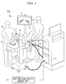
- the medical system 100 of this embodiment includes a manipulator 1 that is inserted into the body of a patient P, as well as an operation input unit 2 and a control unit 3 that are disposed surrounding an operating table on which the patient P lies.
- An endoscope 5 and slave arms 6, as described below, are provided at a distal end of the manipulator 1.
- the control unit 3 controls the manipulator 1 on the basis of the operation applied to the operation input unit 2.
- the operator Op remotely operates the manipulator 1 positioned in the body and can administer treatment to the inside of the body by means of the slave arms 6 provided in the manipulator 1.
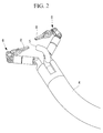
- the manipulator 1 includes an elongated flexible part 4 that is inserted into the body and the endoscope 5 and the slave arms 6 provided at a distal end of the flexible part 4.
- Figs. 1 and 2 show a two-armed manipulator 1 having two slave arms 6, the manipulator 1 may be single-armed, having a single slave arm 6, or may have three or more slave arms 6.
- the slave arms 6 have a plurality of joints and, at the distal end thereof, are provided with a treatment part 8 such as a forceps or an electrocauter.
- the operation input unit 2 includes master arms 9 operated by the operator Op and the display unit 10.
- a master arm 9 is provided for each of the slave arms 6.
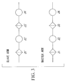
- Fig. 3 schematically shows joint structures of a slave arm 6 and a master arm 9.
- the master arm 9 has a joint structure similar to that of the slave arm 6.
- the slave arm 6 includes a roll joint J1', a yaw joint J2', a roll joint J3', and a yaw joint J4' in that order from the basal end.
- the master arm 9 includes a roll joint J1, a yaw joint J2, a roll joint J3, and a yaw joint J4 in that order from the basal end.
- the roll joints J1', J3', J1, and J3 rotate about a roll axis extending in the longitudinal direction of the arms 6 and 9 from the base to the distal end of each of the arms 6 and 9, and the yaw joints J2', J4', J2, and J4 rotate about a yaw axis orthogonal to the roll axis (orthogonal to the drawing of FIG. 3 ).
- the ratios of the distances between contiguous joints of both the arms 6 and 9 are identical.
- the manipulator 1 rotates each joint Ji' by means of a control signal to move the slave arm 6.
- the medical system 100 of this embodiment further includes a motion-scale-ratio change unit (motion-ratio change unit) 11.
- the motion-scale-ratio change unit 11 is provided, for example, at the operation input unit 2, so that the operator Op can set an arbitrary value as a motion scale ratio.
- the motion-scale-ratio change unit 11 may be provided so as to be capable of switching the motion scale ratio in a step-by-step manner between the scale ratio established by a structure ratio between the master arm 9 and the slave arm 6 and a predetermined value smaller than that scale ratio.
- the motion scale ratio selected by the motion-scale-ratio change unit 11 is transmitted to the control unit 3.
- the control unit 3 switches a control mode for controlling the slave arm 6 between a "first control mode” and a "second control mode" on the basis of the received motion scale ratio.
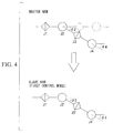
- the "first control mode” is a mode in which the entire slave arm 6 is made to follow the overall motion of the master arm 9. More specifically, as shown in Fig. 4 , the control unit 3 rotates each joint Ji' of the slave arm 6 by the amount equal to the amount of change ⁇ i in each joint Ji of the master arm 9. At this time, the ratio between the amount of operation applied to the master arm 9 and the amount of motion of the slave arm 6 (motion scale ratio) is the structure ratio between the master arm 9 and the slave arm 6. This structure ratio is set in the motion-scale-ratio change unit 11 as a default ratio for the motion scale ratio.
- the "second control mode” is a mode that is selected by the control unit 3 when the received motion scale ratio is below the aforementioned default ratio structurally established in the first control mode and is a mode in which the distal end of the slave arm 6 is made to follow the motion of the distal end of the master arm 9.
- control unit 3 calculates forward kinematics of the master arm 9 using the amount of change ⁇ i in each joint Ji received from the operation input unit 2, thereby calculating displacements dx, dy, dz of the distal end of the master arm 9 in each direction of the motion coordinate system for the master arm 9, as shown in Fig. 5 .
- control unit 3 converts the obtained displacements dx, dy, dz into the displacements dx', dy', dz' in each direction of the operating coordinate system for the slave arm 6.
- control unit 3 calculates reverse kinematics of the slave arm 6 on the basis of the obtained displacements dx', dy', dz' to obtain the amount of rotation ⁇ i' in each joint Ji' of the slave arm 6 as a solution, thereby rotating each joint Ji' by the obtained amount of rotation ⁇ i'.
- the displacements dx', dy', dz' be converted into displacements after having been converted into the coordinate system of the display unit 10 so that the motion direction of the slave arm 6 displayed on the display unit 10 coincides with the operating direction of the master arm 9.
- control unit 3 multiplies the displacements dx', dy', dz' by the motion scale ratio k and uses the obtained displacements kdx', kdy', kdz' for calculating the reverse kinematics.
- This motion scale ratio k is a motion scale ratio set by the operator Op in the motion-scale-ratio change unit 11.
- the displacement of the distal end of the slave arm 6 controlled in this "second control mode" moves in a direction corresponding to the movement direction of the distal end of the master arm 9, the displacement thereof is reduced relative to the displacement of the distal end of the master arm 9. If the motion scale ratio is set, for example, to "0.2,” the displacement of the distal end of the slave arm 6 is one-fifth of the displacement of the master arm 9.
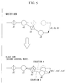
- Fig. 5 shows, for example, two solutions (solution 1, solution 2). If a plurality of solutions are obtained, the control unit 3 adopts the solution that causes the overall shape of the slave arm 6 to be closest to the overall shape of the master arm 9 (solution 2 in the example of Fig. 5 ), for example, the solution that minimizes the total of differences between rotational angles of the corresponding joints Ji and Ji'.
- the flexible part 4 of the manipulator 1 is inserted into the body of the patient P, and the distal end of the manipulator 1 is moved close to an affected area while a video image of the inside of the body acquired by the endoscope 5 is being observed on the display unit 10.
- the operator Op operates the master arm 9 to move the slave arm 6 and administers, to the affected area or a peripheral area thereof, for example, pre-treatment required for treatment of the affected area.
- the operator Op normally causes the slave arm 6 to move in the "first control mode" by means of the motion-scale-ratio change unit 11 (YES in step S1), as shown in Fig. 6 (step S2).
- each joint Ji' of the slave arm 6 is rotated by the amount equal to the amount of change ⁇ i in each joint Ji of the master arm 9 (steps S21, S22), and consequently, the entire slave arm 6 follows the motion of the entire master arm 9 (step S23).
- the operator Op can directly recognize the current shape and orientation of the slave arm 6 from the master arm 9.
- the operator Op can properly operate the slave arm 6, while paying attention to the overall shape of the slave arm 6, for example, checking to see if a cubital part (joints J2, J4) of the slave arm 6 compresses the intraluminal wall.
- the operator positions the treatment part 8 close to the affected area and then causes the motion-scale-ratio change unit 11 to set the motion scale ratio as a value smaller than the default ratio established in the "first control mode," for example, to "0.2" (NO in step S1). By doing so, the slave arm 6 becomes controlled in the "second control mode" (step S3).
- the slave arm 6 is controlled (step S36) so that the distal end of the slave arm 6 follows the motion of the distal end of the master arm 9 (steps S33, S35), on the basis of the movement of the distal end of the master arm 9 (steps S31, S32).
- the amount of motion of the distal end of the slave arm 6 at this time is one-tenth of the amount of operation of the distal end of the master arm 9 (step S34), thus micro-moving the distal end of the slave arm 6 at low speed. Therefore, the operator Op can easily realize minute motion of the treatment part 8 at the distal end of the slave arm 6 and can accurately administer intricate treatment by means of the treatment part 8.
- the entire slave arm 6 can be prevented from moving by a great amount.
- the operator Op can focus attention only on the operation of the distal end of the slave arm 6 without having to pay attention to the overall shape of the slave arm 6.
- a solution that gives a shape close to a right master arm 11R is selected, and the overall shape and orientation of the slave arm 6 roughly correspond to the overall shape and orientation of the master arm 9. Therefore, the operator Op can coarsely recognize the shape and orientation of the slave arm 6 from the master arm 9.
- this embodiment affords an advantage in that the motion scale ratio is changed between a situation requiring a large motion and a situation requiring a minute motion of the slave arm 6, so that the slave arm 6 is allowed to move under a condition appropriate for each of the situations, thereby enhancing usability.
- the slave arm 6 is driven with a motion scale ratio equal to or smaller than the motion scale ratio determined by the structure ratio between both arms 6 and 9, it may be possible that the slave arm 6 is driven with a motion scale ratio greater than the above-described structure ratio.
- the motion scale ratio can be set as a value larger than the above-described structure ratio to allow the entire slave arm 6 to move by a greater amount, which is useful, for example, for coarse treatment of a wide area.
- control unit 3 when the "second control mode" is switched to the "first control mode,” it is preferable that the control unit 3 perform a reset flow before the "first control mode" is started. In the reset flow, the control unit 3 moves at least one of the slave arm 6 and the master arm 9 to allow the positions and the orientations of both arms 6 and 9 to correspond to each other.
- control unit 3 may be performed manually by allowing the operator Op to operate the master arm 9. In this case, because it is difficult to achieve a perfect match between the positions and the orientations of both arms 6 and 9, the control unit 3 may end the reset flow when the shifts of the rotational angles between corresponding joints Ji, Ji' of both arms 6 and 9 fall within a predetermined range. Furthermore, in this case, the control unit 3 may display on the display unit 10 an indication for prompting the operator Op to operate the master arm 9.
- the solution that causes the overall shapes of both arms 6 and 9 to be closest to each other is adopted if a plurality of solutions are obtained as a result of calculating the reverse kinematics, the method for selecting a solution is not limited to this.
- a solution with which the positions of the most distal corresponding joints J4, J4' are matched may be selected.
- the orientation of the treatment part 8 corresponds to the orientation of the distal portion of the master arm 9, the operator Op can operate the treatment part 8 more intuitively.
- first through fourth spaces are four spaces that are obtained by defining a central axis A of a basal part of each of the arms 6 and 9 and that are divided by two planes that pass through the axis A and are orthogonal to each other.
- the overall orientation of the slave arm 6 can be made to correspond to the overall orientation of the master arm 9.
- a medical system 200 according to a second embodiment of the present invention will now be described with reference to Figs. 10 through 16 .
- the medical system 200 differs from that in the first embodiment mainly in that a control-mode manual change unit 12 is provided and in the "second control mode."
- the control-mode manual change unit 12 and the "second control mode" will mainly be described, and structures in common with those in the first embodiment will be denoted with the same reference signs, and descriptions thereof will be omitted.
- the control-mode manual change unit 12 is provided, for example, at the operation input unit 2 such that one of the "first control mode” and the "second control mode” can be selected by the operator Op.
- a signal indicating the control mode selected by the control-mode manual change unit 12 is transmitted to the control unit 3, which then controls the slave arm 6 in the control mode specified by the received signal.
- the "first control mode” is the same as the “first control mode” described in the first embodiment, except in the number of joints, and descriptions thereof will be omitted.
- the procedure up to positioning of the treatment part 8 close to the affected area is the same as in the first embodiment, except that the "first control mode" is selected by the control-mode manual change unit 12 (YES in step S1').
- the operator Op switches the "first control mode” to the "second control mode” with the control-mode manual change unit 12 (NO in step S1').
- the slave arm 6 is controlled (step S36) so that the distal end of the slave arm 6 accurately follows the motion of the distal end of the master arm 9 (steps S33, S35') on the basis of movement of the distal end of the master arm 9 (steps S31, S32).
- the amount of overall motion of the slave arm 6 is suppressed to a minimum (step S35'). Therefore, the operator Op can focus attention only on the operation of the distal end of the slave arm 6 without having to pay attention to the overall shape of the slave arm 6.
- this embodiment affords an advantage in that the entire slave arm 6 is moved normally in a situation requiring a large motion of the slave arm 6, whereas motions of parts other than the distal end of the slave arm 6 are restricted in a situation requiring a minute motion, so that the slave arm 6 can be operated under an operating condition appropriate for each of the situations, thereby enhancing usability.
- the motion-scale-ratio change unit 11 described in the first embodiment may also be provided.
- the control unit 3 may retain a predetermined motion scale ratio k to minutely move the distal end of the slave arm 6 at all times in the "second control mode.”
- reverse kinematics in the "second control mode" are calculated with reference only to the position of the distal end of the slave arm 6.
- the positions and the orientations of some joints at the distal end of the slave arm 6 may be used as a reference.
- a constraint condition may be attached such that an arbitrary number of joints from the distal end of the slave arm 6 take a shape similar to that of the master arm 9, and the reverse kinematics may be calculated so that displacements in the positions and the orientations of the corresponding joints of the master arm 9 are followed.
- a constraint condition like that described above may be attached to all joints J1' to J7' to geometrically calculate the reverse kinematics according to the displacement of the distal end of the master arm 9.
- reverse kinematics of the slave arm 6 may be calculated according to the displacement in the position and orientation of the distal end of the master arm 9, and thereafter, the slave arm 6 may be moved so that any number of joints at the distal end of the slave arm 6 match the motion of the corresponding joints of the master arm 9. If the distal end has undesirably moved when the orientations of the joints were matched, the position thereof is restored to the original position by calculating the reverse kinematics once again. By repeating these operations for calculating displacements, in response to the entered instruction value, in the position and orientation of the distal end of the slave arm 6 until convergence is reached, reverse kinematics can be calculated with the constraint condition applied.
- control unit (control-mode automatic change unit) 3 may automatically switch between the "first control mode” and the “second control mode” depending on the condition, circumstance, or environment in which the slave arm 6 is used.
- the condition of use etc. of the slave arm 6 includes, for example, the type of the slave arm 6, whether or not the movement speed of a joint of the slave arm 6 is within a predetermined threshold, and whether or not the amount of displacement in a joint of the slave arm 6 is within a predetermined threshold.
- the control unit 3 when the slave arm 6 is connected to the control unit 3, the control unit 3 reads out a memory chip provided in the slave arm 6 to recognize the type of the slave arm 6 (e.g., the treatment part 8 as a gripping forceps). The control unit 3 can acquire the control mode corresponding to the recognized type on the basis of prestored table information about types of the slave arm 6 and control modes to switch to an appropriate control mode.
- the type of the slave arm 6 e.g., the treatment part 8 as a gripping forceps.
- the control unit 3 can acquire the control mode corresponding to the recognized type on the basis of prestored table information about types of the slave arm 6 and control modes to switch to an appropriate control mode.
- control unit 3 determines whether or not the region reached by the distal end section of the slave arm 6 is a narrow space, and if this region is a narrow space on the basis of the result of determination, may forcibly select the "second control mode." Whether the space in which the distal end section of the slave arm 6 is positioned is large or small is determined by using, for example, image analysis of video images captured by the endoscope 5.
- control unit 3 may switch the control mode according to the type of the slave arm 6 associated with the master arm 9. For example, the control unit 3 may select the "first control mode” if the slave arm 6 is a retractor surgical instrument used for the purpose of a large motion such as traction or may select the "second control mode” if the slave arm 6 is a surgical energy device used mainly for the purpose of precise operations.
- control unit 3 may recognize the surgical situation on the basis of information including images, the surgical instrument employed, the operative technique, elapsed time, and the circumstances of the operating theater, thereby switching to the most appropriate control mode.
- control unit 3 may determine whether coarse-motion operation of the entire slave arm 6 or minute-motion operation of the distal end of the slave arm 6 is performed by the operator Op on the basis of the amount of change ⁇ i in each joint Ji of the master arm 9, thereby switching between the "first control mode” and the "second control mode” on the basis of the determination result.
- control unit 3 may switch to the "second control mode.”
Landscapes
- Engineering & Computer Science (AREA)
- Health & Medical Sciences (AREA)
- Robotics (AREA)
- Life Sciences & Earth Sciences (AREA)
- Surgery (AREA)
- Mechanical Engineering (AREA)
- Heart & Thoracic Surgery (AREA)
- Biomedical Technology (AREA)
- Nuclear Medicine, Radiotherapy & Molecular Imaging (AREA)
- Medical Informatics (AREA)
- Molecular Biology (AREA)
- Animal Behavior & Ethology (AREA)
- General Health & Medical Sciences (AREA)
- Public Health (AREA)
- Veterinary Medicine (AREA)
- Manipulator (AREA)
Abstract
Description
- The present invention relates to a medical system and a method for controlling the same.
- As an operation input apparatus for remotely operating a slave arm having a joint, in the related art there is a known medical system provided with a master arm having a joint structure similar to the joint structure of the slave arm is known (e.g., refer to Patent Literatures PTL 1 and
PTL 2 below). In such a system, because the slave arm can be made to reproduce a motion corresponding to the motion of the master arm, an operator can intuitively operate the slave arm while directly recognizing the shape and motion of the slave arm from the shape and motion of the master arm. -
- {PTL 1} Publication of Japanese Patent No.
3583777 - {PTL 2} Publication of Japanese Patent No.
4608601 - {PTL 3} Publication of Japanese Patent No.
4176126 - During an actual surgical operation, it is necessary to move the slave arm not only minutely but also by a comparatively great amount when, for example, pulling an affected area or tying a knot after hooking a needle. In this case, because an operator needs to pay attention to the positional relationship between the slave arm and peripheral tissues inside the body of the patient, he or she wishes to accurately perceive the shape and orientation of the entire slave arm, including the joint part. Meanwhile, when performing intricate treatment of, for example, the affected area, it is necessary to accurately move a distal end of the slave arm provided with a distal treatment part. In this case, the operator wishes to focus attention only on the operation of the distal end of the slave arm without paying attention to the overall shape or orientation of the slave arm.
- On the other hand, scale conversion techniques between a master and a slave that differ in structure are generally well known (e.g., refer to Patent Literature PTL 3). In contrast, for a master and a slave that are similar in structure, such as for the system of
Patent Literatures PTL 1 andPTL 2, the ratio of the amount of motion of the slave arm to the amount of operation of the master arm (motion scale ratio) is uniquely determined according to the structure ratio between the master arm and the slave arm, and it may not be possible to change the operating condition of the slave arm, depending on the circumstances. Thus, contradictory demands, such as coarse treatment and minute treatment of the affected area, in different situations cannot be satisfied, leading to a problem of poor usability. - The present invention has been conceived in light of the above-described circumstances, and an object thereof is to provide a medical system and a method for controlling the same that are capable of satisfying both coarse operation and intricate operation of the slave arm to enhance usability while still maintaining intuitive operability of the slave arm using a master arm that is structurally similar to the slave arm.
- In order to achieve the above-described object, the present invention provides the following solutions.
- A first aspect of the present invention is a medical system including: a multi-joint slave arm; a master arm that has a joint structure structurally similar to the slave arm and is operated by an operator; and a control unit that controls the slave arm on the basis of an operation applied to the master arm, wherein the control unit can switch between a first control mode for controlling a rotational motion of each joint of the slave arm on the basis of an amount of rotation of each joint of the master arm so that the slave arm takes a shape similar to the master arm and a second control mode for controlling the rotational motion of each joint of the slave arm on the basis of a displacement of a predetermined region of a distal end section of the master arm so that a predetermined region of a distal end section of the slave arm follows a movement of the predetermined region of the distal end section of the master arm.
- According to the first aspect of the present invention, because the slave arm and the master arm are similar to each other in the joint structure, the slave arm can be intuitively operated using the master arm.
- In this case, the control unit causes the entire slave arm to follow the overall motion of the master arm in the first control mode. Therefore, the first control mode is suitable for coarse operation in which the slave arm is moved by a comparatively great amount. In contrast, in the second control mode, the control unit causes the predetermined region at the distal end section of the slave arm to follow the motion of the predetermined region at the distal end section of the master arm. Therefore, the second control mode is suitable for an intricate operation in which the predetermined region at the distal end section of the slave arm is accurately operated. In this manner, both coarse operation and intricate operation can be satisfied to enhance usability.
- In the above-described first aspect, the control unit may control the slave arm so as to minimize an amount of change in a shape of the slave arm in the second control mode.
- By doing so, because the amount of overall motion of the slave arm is suppressed to a minimum, the operator can further focus attention on the operation of the predetermined region at the distal end section of the slave arm.
- Furthermore, in the above-described first aspect, the slave arm may be controlled so as to minimize the motion of a pre-registered particular joint (e.g., a joint highly likely to interfere with tissues due to its structure).
- In the above-described first aspect, the control unit may control a rotational motion of any number of joints starting from a distal end of the slave arm so that these joints take a shape similar to the master arm in the second control mode.
- By doing so, the distal end section of the slave arm can be operated more intuitively.
- In the above-described first aspect, a ratio of an amount of motion of the slave arm to an amount of operation applied to the master arm may be a predetermined constant value in the first control mode and may be smaller than the predetermined constant value in the second control mode.
- By doing so, the amount of motion of the slave arm in the second control mode becomes smaller than that in the first control mode. Because of this, the second control mode can be made even more suitable for an intricate operation.
- In the above-described first aspect, a ratio of an amount of motion of the slave arm to an amount of operation applied to the master arm may be a predetermined constant value in the first control mode and may be smaller than the predetermined constant value in the second control mode, and in the second mode, the control unit may calculate reverse kinematics of the slave arm on the basis of a position of the predetermined region of the distal end section of the master arm and may select, from among an obtained plurality of solutions, a solution that causes the shape of the slave arm to be closest to the shape of the master arm.
- By doing so, not only can the second control mode be made more suitable for intricate operation, but also the shape and the orientation of the slave arm can be coarsely recognized on the basis of the master arm.
- In the above-described first aspect, the control unit may select a solution that minimizes a total of differences between an amount of displacement of each joint of the master arm and an amount of displacement of each joint of the slave arm in the second control mode.
- Furthermore, in the above-described first aspect, if four spaces defined by two planes that pass through a central axis of a basal part of each of the slave arm and the master arm and that are orthogonal to each other on the central axis are assumed, the control unit may select a solution that causes the slave arm to be positioned in a space corresponding to a space in which the master arm is positioned.
- By doing so, a solution that causes the shape and the orientation of the slave arm to approximate to the shape and the orientation of the master arm can be selected via a simple calculation.
- In the above-described first aspect, in the second control mode, the control unit may control the slave arm so as to place a most distal joint of the slave arm at a position and an orientation corresponding to a position and an orientation of a most distal joint of the master arm.
- The above-described first aspect may include a motion-ratio change unit that changes the ratio of the amount of motion to the amount of operation.
- By doing so, the ratio can be changed to an appropriate value, as required, to further enhance usability.
- The above-described first aspect may include a control-mode manual change unit that allows the operator to select one of the first control mode and the second control mode.
- By doing so, the operator can switch the control mode with an arbitrary timing. The control-mode manual change unit may be an input device like a switch.
- The above-described first aspect may include a control-mode automatic change unit that switches the control mode depending on a condition, circumstance, or environment of use of the slave arm.
- By doing so, it is possible to automatically switch to an appropriate control mode with an appropriate timing.
- In the above-described first aspect, the control-mode automatic change unit may switch between the first control mode and the second control mode depending on a type of the slave arm.
- By doing so, it is possible to automatically switch to a control mode suitable for the application of individual slave arms.
- In the above-described first aspect, when switching from the second control mode to the first control mode, the control unit may perform a reset flow for moving at least one of the master arm and the slave arm before the first control mode is started so as to match the amounts of displacements of individual joints of the master arm and the slave arm.
- By doing so, the first control mode can be smoothly started in a state where the overall positions and orientations of the master arm and the slave arm are matched.
- A second aspect of the present invention is a method for controlling a medical system including a multi-joint slave arm and a master arm that has a joint structure structurally similar to the slave arm and that is operated by an operator, wherein a control mode for controlling the slave arm can be switched between a first control mode for controlling a rotational motion of each joint of the slave arm on the basis of an amount of rotation of each joint of the master arm so that the slave arm takes a shape similar to the master arm and a second control mode for controlling a rotational motion of each joint of the slave arm on the basis of a displacement of a predetermined region of a distal end section of the master arm so that a predetermined region of a distal end section of the slave arm follows a movement of the predetermined region of the distal end section of the master arm.
- The present invention affords an advantage in that both coarse operation and intricate operation can be satisfied to enhance usability using a master arm that is structurally similar to the slave arm, while still maintaining intuitive operability of the slave arm.
-
- {
Fig. 1} Fig. 1 is a block diagram depicting the overall structure of a medical system according to a first embodiment of the present invention. - {
Fig. 2} Fig. 2 is an outside view depicting the structure of a distal portion of a manipulator provided in the medical system inFig. 1 . - {
Fig. 3} Fig. 3 is a diagram schematically depicting joint structures of a slave arm and a master arm provided in the medical system inFig. 1 . - {
Fig. 4} Fig. 4 is a diagram for explaining an operation in a first control mode of the slave arm inFig. 3 . - {
Fig. 5} Fig. 5 is a diagram for explaining an operation in a second control mode of the slave arm inFig. 3 . - {
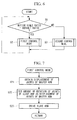
Fig. 6} Fig. 6 is a flowchart illustrating a method for controlling the manipulator with a control unit of the medical system inFig. 1 . - {
Fig. 7} Fig. 7 is a flowchart illustrating a routine for the first control mode inFig. 6 . - {
Fig. 8} Fig. 8 is a flowchart illustrating a routine for the second control mode inFig. 6 . - {
Fig. 9} Fig. 9 is a diagram for explaining a modification of a method for selecting a solution to reverse kinematics. - {
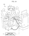
Fig. 10} Fig. 10 is a block diagram depicting the overall structure of a medical system according to a second embodiment of the present invention. - {
Fig. 11} Fig. 11 is a diagram schematically depicting a joint structure of a slave arm and a master arm provided in the medical system inFig. 10 . - {
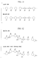
Fig. 12} Fig. 12 is a diagram for explaining an operation in a first control mode of the slave arm inFig. 11 . - {
Fig. 13} Fig. 13 is a diagram for explaining an operation in a second control mode of the slave arm inFig. 11 . - {
Fig. 14} Fig. 14 is a flowchart illustrating a method for controlling a manipulator with a control unit of the medical system inFig. 10 . - {
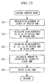
Fig. 15} Fig. 15 is a flowchart illustrating a routine for the second control mode inFig. 14 . - {
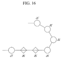
Fig. 16} Fig. 16 is a diagram for explaining a modification of a method for switching the control mode. - A
medical system 100 according to a first embodiment of the present invention will now be described with reference to the drawings. - As shown in
Fig. 1 , themedical system 100 of this embodiment includes amanipulator 1 that is inserted into the body of a patient P, as well as anoperation input unit 2 and acontrol unit 3 that are disposed surrounding an operating table on which the patient P lies. - First of all, the outline of the
medical system 100 will be described. Anendoscope 5 andslave arms 6, as described below, are provided at a distal end of themanipulator 1. When an operator Op inserts themanipulator 1 into the body of the patient P via the anus and operates theoperation input unit 2 while observing an intracorporeal image acquired by theendoscope 5, on adisplay unit 10 provided at theoperation input unit 2, thecontrol unit 3 controls themanipulator 1 on the basis of the operation applied to theoperation input unit 2. By doing so, the operator Op remotely operates themanipulator 1 positioned in the body and can administer treatment to the inside of the body by means of theslave arms 6 provided in themanipulator 1. - Each structure of the
medical system 100 will now be described. - As shown in
Fig. 2 , themanipulator 1 includes an elongated flexible part 4 that is inserted into the body and theendoscope 5 and theslave arms 6 provided at a distal end of the flexible part 4. AlthoughFigs. 1 and2 show a two-armed manipulator 1 having twoslave arms 6, themanipulator 1 may be single-armed, having asingle slave arm 6, or may have three ormore slave arms 6. - The
slave arms 6 have a plurality of joints and, at the distal end thereof, are provided with atreatment part 8 such as a forceps or an electrocauter. - The
operation input unit 2 includesmaster arms 9 operated by the operator Op and thedisplay unit 10. Amaster arm 9 is provided for each of theslave arms 6. -
Fig. 3 schematically shows joint structures of aslave arm 6 and amaster arm 9. As shown inFig. 3 , themaster arm 9 has a joint structure similar to that of theslave arm 6. In the present example, theslave arm 6 includes a roll joint J1', a yaw joint J2', a roll joint J3', and a yaw joint J4' in that order from the basal end. Likewise, themaster arm 9 includes a roll joint J1, a yaw joint J2, a roll joint J3, and a yaw joint J4 in that order from the basal end. The roll joints J1', J3', J1, and J3 rotate about a roll axis extending in the longitudinal direction of thearms arms FIG. 3 ). In addition, the ratios of the distances between contiguous joints of both thearms - Each joint Ji (i=1, 2, 3, 4) of the
master arm 9 is provided with an angle detector, such as an encoder. Theoperation input unit 2 detects the amount of change θi (i=1, 2, 3, 4) in the angle of each joint Ji with the angle detector and outputs the detected four amounts of change θi to thecontrol unit 3 as operation signals. - The
control unit 3 generates a drive signal for driving each joint Ji' (i=1, 2, 3, 4) of theslave arm 6 on the basis of the operation signals received from theoperation input unit 2 and transmits the generated drive signal to themanipulator 1. Themanipulator 1 rotates each joint Ji' by means of a control signal to move theslave arm 6. - The
medical system 100 of this embodiment further includes a motion-scale-ratio change unit (motion-ratio change unit) 11. The motion-scale-ratio change unit 11 is provided, for example, at theoperation input unit 2, so that the operator Op can set an arbitrary value as a motion scale ratio. Here, the motion scale ratio is defined by the following expression, as described in detail below.
- The motion-scale-
ratio change unit 11 may be provided so as to be capable of switching the motion scale ratio in a step-by-step manner between the scale ratio established by a structure ratio between themaster arm 9 and theslave arm 6 and a predetermined value smaller than that scale ratio. - The motion scale ratio selected by the motion-scale-
ratio change unit 11 is transmitted to thecontrol unit 3. Thecontrol unit 3 switches a control mode for controlling theslave arm 6 between a "first control mode" and a "second control mode" on the basis of the received motion scale ratio. - A method for controlling the
slave arm 6 by thiscontrol unit 3 will now be described in detail. - The "first control mode" is a mode in which the
entire slave arm 6 is made to follow the overall motion of themaster arm 9. More specifically, as shown inFig. 4 , thecontrol unit 3 rotates each joint Ji' of theslave arm 6 by the amount equal to the amount of change θi in each joint Ji of themaster arm 9. At this time, the ratio between the amount of operation applied to themaster arm 9 and the amount of motion of the slave arm 6 (motion scale ratio) is the structure ratio between themaster arm 9 and theslave arm 6. This structure ratio is set in the motion-scale-ratio change unit 11 as a default ratio for the motion scale ratio. - The "second control mode" is a mode that is selected by the
control unit 3 when the received motion scale ratio is below the aforementioned default ratio structurally established in the first control mode and is a mode in which the distal end of theslave arm 6 is made to follow the motion of the distal end of themaster arm 9. - More specifically, the
control unit 3 calculates forward kinematics of themaster arm 9 using the amount of change θi in each joint Ji received from theoperation input unit 2, thereby calculating displacements dx, dy, dz of the distal end of themaster arm 9 in each direction of the motion coordinate system for themaster arm 9, as shown inFig. 5 . Next, thecontrol unit 3 converts the obtained displacements dx, dy, dz into the displacements dx', dy', dz' in each direction of the operating coordinate system for theslave arm 6. Then, thecontrol unit 3 calculates reverse kinematics of theslave arm 6 on the basis of the obtained displacements dx', dy', dz' to obtain the amount of rotation θi' in each joint Ji' of theslave arm 6 as a solution, thereby rotating each joint Ji' by the obtained amount of rotation θi'. - It is desirable that the displacements dx', dy', dz' be converted into displacements after having been converted into the coordinate system of the
display unit 10 so that the motion direction of theslave arm 6 displayed on thedisplay unit 10 coincides with the operating direction of themaster arm 9. - Here, the
control unit 3 multiplies the displacements dx', dy', dz' by the motion scale ratio k and uses the obtained displacements kdx', kdy', kdz' for calculating the reverse kinematics. This motion scale ratio k is a motion scale ratio set by the operator Op in the motion-scale-ratio change unit 11. - Although the distal end of the
slave arm 6 controlled in this "second control mode" moves in a direction corresponding to the movement direction of the distal end of themaster arm 9, the displacement thereof is reduced relative to the displacement of the distal end of themaster arm 9. If the motion scale ratio is set, for example, to "0.2," the displacement of the distal end of theslave arm 6 is one-fifth of the displacement of themaster arm 9. - Here, in reverse kinematics, because two or more combinations of the amounts of rotation θi' are possible for moving the distal end of the
slave arm 6 by displacements kdx', kdy', kdz', as shown inFig. 5 , two or more solutions to reverse kinematics are possible, accordingly.Fig. 5 shows, for example, two solutions (solution 1, solution 2). If a plurality of solutions are obtained, thecontrol unit 3 adopts the solution that causes the overall shape of theslave arm 6 to be closest to the overall shape of the master arm 9 (solution 2 in the example ofFig. 5 ), for example, the solution that minimizes the total of differences between rotational angles of the corresponding joints Ji and Ji'. - Next, the operation of the
medical system 100 with the aforementioned structure will now be described with reference toFigs. 6 through 8 . - In order to administer treatment to the inside of the body of the patient P using the
medical system 100 of this embodiment, the flexible part 4 of themanipulator 1 is inserted into the body of the patient P, and the distal end of themanipulator 1 is moved close to an affected area while a video image of the inside of the body acquired by theendoscope 5 is being observed on thedisplay unit 10. Next, while observing the video image displayed on thedisplay unit 10, the operator Op operates themaster arm 9 to move theslave arm 6 and administers, to the affected area or a peripheral area thereof, for example, pre-treatment required for treatment of the affected area. - At this time, the operator Op normally causes the
slave arm 6 to move in the "first control mode" by means of the motion-scale-ratio change unit 11 (YES in step S1), as shown inFig. 6 (step S2). - As shown in
Fig. 7 , in the "first control mode," each joint Ji' of theslave arm 6 is rotated by the amount equal to the amount of change θi in each joint Ji of the master arm 9 (steps S21, S22), and consequently, theentire slave arm 6 follows the motion of the entire master arm 9 (step S23). In other words, because the shape and orientation of theentire master arm 9 correspond to the shape and orientation of theentire slave arm 6, the operator Op can directly recognize the current shape and orientation of theslave arm 6 from themaster arm 9. For this reason, while operating theslave arm 6 in a narrow lumen, the operator Op can properly operate theslave arm 6, while paying attention to the overall shape of theslave arm 6, for example, checking to see if a cubital part (joints J2, J4) of theslave arm 6 compresses the intraluminal wall. - Next, for the treatment of the affected area, the operator Op positions the
treatment part 8 close to the affected area and then causes the motion-scale-ratio change unit 11 to set the motion scale ratio as a value smaller than the default ratio established in the "first control mode," for example, to "0.2" (NO in step S1). By doing so, theslave arm 6 becomes controlled in the "second control mode" (step S3). - As shown in
Fig. 8 , in the "second control mode," theslave arm 6 is controlled (step S36) so that the distal end of theslave arm 6 follows the motion of the distal end of the master arm 9 (steps S33, S35), on the basis of the movement of the distal end of the master arm 9 (steps S31, S32). The amount of motion of the distal end of theslave arm 6 at this time is one-tenth of the amount of operation of the distal end of the master arm 9 (step S34), thus micro-moving the distal end of theslave arm 6 at low speed. Therefore, the operator Op can easily realize minute motion of thetreatment part 8 at the distal end of theslave arm 6 and can accurately administer intricate treatment by means of thetreatment part 8. - Furthermore, in the "second control mode," as long as the distal end of the
slave arm 6 is moved within a restricted range of the affected area and surroundings thereof, theentire slave arm 6 can be prevented from moving by a great amount. As a result, the operator Op can focus attention only on the operation of the distal end of theslave arm 6 without having to pay attention to the overall shape of theslave arm 6. Furthermore, when a plurality of solutions are obtained as a result of calculating the reverse kinematics in step S33, a solution that gives a shape close to a right master arm 11R is selected, and the overall shape and orientation of theslave arm 6 roughly correspond to the overall shape and orientation of themaster arm 9. Therefore, the operator Op can coarsely recognize the shape and orientation of theslave arm 6 from themaster arm 9. - In this manner, this embodiment affords an advantage in that the motion scale ratio is changed between a situation requiring a large motion and a situation requiring a minute motion of the
slave arm 6, so that theslave arm 6 is allowed to move under a condition appropriate for each of the situations, thereby enhancing usability. - Although, in this embodiment, the
slave arm 6 is driven with a motion scale ratio equal to or smaller than the motion scale ratio determined by the structure ratio between botharms slave arm 6 is driven with a motion scale ratio greater than the above-described structure ratio. - By doing so, the motion scale ratio can be set as a value larger than the above-described structure ratio to allow the
entire slave arm 6 to move by a greater amount, which is useful, for example, for coarse treatment of a wide area. - Furthermore, in this embodiment, when the "second control mode" is switched to the "first control mode," it is preferable that the
control unit 3 perform a reset flow before the "first control mode" is started. In the reset flow, thecontrol unit 3 moves at least one of theslave arm 6 and themaster arm 9 to allow the positions and the orientations of botharms - Instead of automatically executing the above-described reset flow by the
control unit 3, it may be performed manually by allowing the operator Op to operate themaster arm 9. In this case, because it is difficult to achieve a perfect match between the positions and the orientations of botharms control unit 3 may end the reset flow when the shifts of the rotational angles between corresponding joints Ji, Ji' of botharms control unit 3 may display on thedisplay unit 10 an indication for prompting the operator Op to operate themaster arm 9. - Although, in this embodiment, the solution that causes the overall shapes of both
arms - For example, a solution with which the positions of the most distal corresponding joints J4, J4' are matched may be selected. In this case, because the orientation of the
treatment part 8 corresponds to the orientation of the distal portion of themaster arm 9, the operator Op can operate thetreatment part 8 more intuitively. - Alternatively, from among first through fourth spaces as shown in
Fig. 9 , a solution that ensures that theslave arm 6 is located in the quadrant identical to that in which themaster arm 9 is located may be adopted. The first through fourth spaces are four spaces that are obtained by defining a central axis A of a basal part of each of thearms slave arm 6 can be made to correspond to the overall orientation of themaster arm 9. - A
medical system 200 according to a second embodiment of the present invention will now be described with reference toFigs. 10 through 16 . - As shown in
Fig. 10 , themedical system 200 according to this embodiment differs from that in the first embodiment mainly in that a control-modemanual change unit 12 is provided and in the "second control mode." For this reason, in this embodiment, the control-modemanual change unit 12 and the "second control mode" will mainly be described, and structures in common with those in the first embodiment will be denoted with the same reference signs, and descriptions thereof will be omitted. - In this embodiment, as shown in
Fig. 11 , theslave arm 6 and themaster arm 9 having comparatively many (seven in the present example) joints Ji', Ji (i=1, 2, ..., 7) will be described. Also in this embodiment, theslave arm 6 and themaster arm 9 have a joint structure similar to each other. In this embodiment, theslave arm 6 and themaster arm 9 having a comparatively small number of joints, as described in the first embodiment, may also be used. - The control-mode
manual change unit 12 is provided, for example, at theoperation input unit 2 such that one of the "first control mode" and the "second control mode" can be selected by the operator Op. A signal indicating the control mode selected by the control-modemanual change unit 12 is transmitted to thecontrol unit 3, which then controls theslave arm 6 in the control mode specified by the received signal. - Next, a method for controlling the
slave arm 6 by thiscontrol unit 3 will be described in detail. As shown inFig. 12 , the "first control mode" is the same as the "first control mode" described in the first embodiment, except in the number of joints, and descriptions thereof will be omitted. - The "second control mode" is a mode that causes the distal end of the
slave arm 6 to follow the motion of the distal end of themaster arm 9. More specifically, as shown inFig. 13 , thecontrol unit 3 uses the amount of change θi (i=1, 2, ..., 7) in each joint Ji received from theoperation input unit 2 to obtain the displacements dx', dy', dz' of the distal end of theslave arm 6 via a procedure similar to that in the first embodiment and by the use of these displacements dx', dy', dz', calculates the reverse kinematics of theslave arm 6. Here, if a plurality of solutions are obtained, thecontrol unit 3 adopts the solution that minimizes the total of the amounts of rotation θi' (i=1, 2, ..., 7) of the joints Ji', namely, the solution that minimizes the amount of the overall motion of theslave arm 6. - The operation of the
medical system 200 with this structure will now be described with reference toFigs. 14 and15 . In this embodiment, the procedure up to positioning of thetreatment part 8 close to the affected area is the same as in the first embodiment, except that the "first control mode" is selected by the control-mode manual change unit 12 (YES in step S1'). - As shown in
Fig. 14 , after positioning thetreatment part 8 close to the affected area, the operator Op switches the "first control mode" to the "second control mode" with the control-mode manual change unit 12 (NO in step S1'). As shown inFig. 15 , in the "second control mode" of this embodiment, theslave arm 6 is controlled (step S36) so that the distal end of theslave arm 6 accurately follows the motion of the distal end of the master arm 9 (steps S33, S35') on the basis of movement of the distal end of the master arm 9 (steps S31, S32). At this time, however, the amount of overall motion of theslave arm 6 is suppressed to a minimum (step S35'). Therefore, the operator Op can focus attention only on the operation of the distal end of theslave arm 6 without having to pay attention to the overall shape of theslave arm 6. - In this manner, this embodiment affords an advantage in that the
entire slave arm 6 is moved normally in a situation requiring a large motion of theslave arm 6, whereas motions of parts other than the distal end of theslave arm 6 are restricted in a situation requiring a minute motion, so that theslave arm 6 can be operated under an operating condition appropriate for each of the situations, thereby enhancing usability. - Also in this embodiment, it is preferable to perform the reset flow in the same manner as in the first embodiment when the
control unit 3 is to switch the "second control mode" to the "first control mode." - Furthermore, in this embodiment, the motion-scale-
ratio change unit 11 described in the first embodiment may also be provided. In this case, for calculating the reverse kinematics in the "second control mode," it is sufficient to use displacements kdx', kdy', kdz' instead of the displacements dx', dy', dz'. Alternatively, thecontrol unit 3 may retain a predetermined motion scale ratio k to minutely move the distal end of theslave arm 6 at all times in the "second control mode." - In this embodiment, reverse kinematics in the "second control mode" are calculated with reference only to the position of the distal end of the
slave arm 6. Instead of this, the positions and the orientations of some joints at the distal end of theslave arm 6 may be used as a reference. - More specifically, a constraint condition may be attached such that an arbitrary number of joints from the distal end of the
slave arm 6 take a shape similar to that of themaster arm 9, and the reverse kinematics may be calculated so that displacements in the positions and the orientations of the corresponding joints of themaster arm 9 are followed. - In this case, a constraint condition like that described above may be attached to all joints J1' to J7' to geometrically calculate the reverse kinematics according to the displacement of the distal end of the
master arm 9. - Alternatively, reverse kinematics of the
slave arm 6 may be calculated according to the displacement in the position and orientation of the distal end of themaster arm 9, and thereafter, theslave arm 6 may be moved so that any number of joints at the distal end of theslave arm 6 match the motion of the corresponding joints of themaster arm 9. If the distal end has undesirably moved when the orientations of the joints were matched, the position thereof is restored to the original position by calculating the reverse kinematics once again. By repeating these operations for calculating displacements, in response to the entered instruction value, in the position and orientation of the distal end of theslave arm 6 until convergence is reached, reverse kinematics can be calculated with the constraint condition applied. - In this embodiment, the operator Op manually switches between the "first control mode" and the "second control mode." Instead of or in addition to this, the control unit (control-mode automatic change unit) 3 may automatically switch between the "first control mode" and the "second control mode" depending on the condition, circumstance, or environment in which the
slave arm 6 is used. - The condition of use etc. of the
slave arm 6 includes, for example, the type of theslave arm 6, whether or not the movement speed of a joint of theslave arm 6 is within a predetermined threshold, and whether or not the amount of displacement in a joint of theslave arm 6 is within a predetermined threshold. - For example, in
Fig. 1 , when theslave arm 6 is connected to thecontrol unit 3, thecontrol unit 3 reads out a memory chip provided in theslave arm 6 to recognize the type of the slave arm 6 (e.g., thetreatment part 8 as a gripping forceps). Thecontrol unit 3 can acquire the control mode corresponding to the recognized type on the basis of prestored table information about types of theslave arm 6 and control modes to switch to an appropriate control mode. - For example, when a U-turn motion for reconfiguring the
slave arm 6 into a U-shape is to be performed, as shown inFig. 16 , this motion may be followed by forcible selection of the "second control mode" by thecontrol unit 3. - Furthermore, the
control unit 3 determines whether or not the region reached by the distal end section of theslave arm 6 is a narrow space, and if this region is a narrow space on the basis of the result of determination, may forcibly select the "second control mode." Whether the space in which the distal end section of theslave arm 6 is positioned is large or small is determined by using, for example, image analysis of video images captured by theendoscope 5. - In addition, the
control unit 3 may switch the control mode according to the type of theslave arm 6 associated with themaster arm 9. For example, thecontrol unit 3 may select the "first control mode" if theslave arm 6 is a retractor surgical instrument used for the purpose of a large motion such as traction or may select the "second control mode" if theslave arm 6 is a surgical energy device used mainly for the purpose of precise operations. - Furthermore, the
control unit 3 may recognize the surgical situation on the basis of information including images, the surgical instrument employed, the operative technique, elapsed time, and the circumstances of the operating theater, thereby switching to the most appropriate control mode. - Alternatively, the
control unit 3 may determine whether coarse-motion operation of theentire slave arm 6 or minute-motion operation of the distal end of theslave arm 6 is performed by the operator Op on the basis of the amount of change θi in each joint Ji of themaster arm 9, thereby switching between the "first control mode" and the "second control mode" on the basis of the determination result. - Or alternatively, when one of the rotational angles of the joints Ji has reached the maximum angle during control in the "first control mode," the
control unit 3 may switch to the "second control mode." -
- 1
- Manipulator
- 2
- Operation input unit
- 3
- Control unit (control-mode automatic change unit)
- 4
- Insertion section
- 5
- Endoscope
- 6
- Slave arm
- 8
- Distal treatment part
- 9
- Master arm
- 10
- Display unit
- 11
- Motion-scale-ratio change unit (motion-ratio change unit)
- 12
- Control-mode manual change unit
- 100, 200
- Medical system
- J1 to J7, J1' to J7'
- Joint
- Op
- Operator
- P
- Patient
Claims (14)
- A medical system comprising:a multi-joint slave arm;a master arm that has a joint structure structurally similar to the slave arm and is operated by an operator; anda control unit that controls the slave arm on the basis of an operation applied to the master arm,wherein the control unit can switch between a first control mode for controlling a rotational motion of each joint of the slave arm on the basis of an amount of rotation of each joint of the master arm so that the slave arm takes a shape similar to the master arm and a second control mode for controlling the rotational motion of each joint of the slave arm on the basis of a displacement of a predetermined region of a distal end section of the master arm so that a predetermined region of a distal end section of the slave arm follows a movement of the predetermined region of the distal end section of the master arm.
- The medical system according to claim 1, wherein the control unit controls the slave arm so as to minimize an amount of change in a shape of the slave arm in the second control mode.
- The medical system according to claim 1 or claim 2, wherein the control unit controls a rotational motion of any number of joints starting from a distal end of the slave arm so that said joints take a shape similar to the master arm in the second control mode.
- The medical system according to one of claims 1 to 3, wherein a ratio of an amount of motion of the slave arm to an amount of operation applied to the master arm is a predetermined constant value in the first control mode and is smaller than the predetermined constant value in the second control mode.
- The medical system according to claim 1, wherein a ratio of an amount of motion of the slave arm to an amount of operation applied to the master arm is a predetermined constant value in the first control mode and is smaller than the predetermined constant value in the second control mode, and
in the second mode, the control unit calculates reverse kinematics of the slave arm on the basis of a position of the predetermined region of the distal end section of the master arm and selects, from among an obtained plurality of solutions, a solution that causes the shape of the slave arm to be closest to the shape of the master arm. - The medical system according to claim 5, wherein the control unit selects a solution that minimizes a total of differences between an amount of displacement of each joint of the master arm and an amount of displacement of each joint of the slave arm in the second control mode.
- The medical system according to claim 5, wherein if four spaces defined by two planes that pass through a central axis of a basal part of each of the slave arm and the master arm and that are orthogonal to each other on the central axis are assumed, the control unit selects a solution that causes the slave arm to be positioned in a space corresponding to a space in which the master arm is positioned.
- The medical system according to claim 5, wherein in the second control mode, the control unit controls the slave arm so as to place a most distal joint of the slave arm at a position and an orientation corresponding to a position and an orientation of a most distal joint of the master arm.
- The medical system according to one of claims 4 to 7, comprising a motion-ratio change unit that changes the ratio of the amount of motion to the amount of operation.
- The medical system according to one of claims 1 to 8, comprising a control-mode manual change unit that allows the operator to select one of the first control mode and the second control mode.
- The medical system according to one of claims 1 to 10, comprising a control-mode automatic change unit that switches between the first control mode and the second control mode depending on a condition, circumstance, or environment of use of the slave arm.
- The medical system according to claim 11, wherein the control-mode automatic change unit switches between the first control mode and the second control mode depending on a type of the slave arm.
- The medical system according to one of claims 1 to 12, wherein when switching from the second control mode to the first control mode, the control unit performs a reset flow for moving at least one of the master arm and the slave arm before the first control mode is started so as to match the amounts of displacements of individual joints of the master arm and the slave arm.
- A method for controlling a medical system including a multi-joint slave arm and a master arm that has a joint structure structurally similar to the slave arm and that is operated by an operator,
wherein a control mode for controlling the slave arm can be switched between a first control mode for controlling a rotational motion of each joint of the slave arm on the basis of an amount of rotation of each joint of the master arm so that the slave arm takes a shape similar to the master arm and a second control mode for controlling a rotational motion of each joint of slave arm on the basis of a displacement of a predetermined region of a distal end section of the master arm so that a predetermined region of a distal end section of the slave arm follows a movement of the predetermined region of the distal end section of the master arm.
Applications Claiming Priority (2)
| Application Number | Priority Date | Filing Date | Title |
|---|---|---|---|
| JP2013155885A JP6164964B2 (en) | 2013-07-26 | 2013-07-26 | Medical system and control method thereof |
| PCT/JP2014/069260 WO2015012241A1 (en) | 2013-07-26 | 2014-07-18 | Medical system and control method for same |
Publications (2)
| Publication Number | Publication Date |
|---|---|
| EP3025672A1 true EP3025672A1 (en) | 2016-06-01 |
| EP3025672A4 EP3025672A4 (en) | 2017-01-04 |
Family
ID=52393279
Family Applications (1)
| Application Number | Title | Priority Date | Filing Date |
|---|---|---|---|
| EP14829493.7A Withdrawn EP3025672A4 (en) | 2013-07-26 | 2014-07-18 | Medical system and control method for same |
Country Status (5)
| Country | Link |
|---|---|
| US (1) | US10155315B2 (en) |
| EP (1) | EP3025672A4 (en) |
| JP (1) | JP6164964B2 (en) |
| CN (1) | CN105407827B (en) |
| WO (1) | WO2015012241A1 (en) |
Cited By (3)
| Publication number | Priority date | Publication date | Assignee | Title |
|---|---|---|---|---|
| EP3263062A4 (en) * | 2015-02-26 | 2018-11-14 | Olympus Corporation | Medical manipulator system |
| EP3386421A4 (en) * | 2015-12-10 | 2019-11-20 | Covidien LP | ROBOTIC SURGICAL SYSTEMS WITH INDEPENDENT ROLLING SCALES, TANGING, AND LACET |
| GB2605808A (en) * | 2021-04-14 | 2022-10-19 | Prec Robotics Limited | An apparatus, computer-implemented method and computer program |
Families Citing this family (44)
| Publication number | Priority date | Publication date | Assignee | Title |
|---|---|---|---|---|
| US12402960B2 (en) | 2010-10-11 | 2025-09-02 | Ecole Polytechnique Federale De Lausanne (Epfl) | Mechanical manipulator for surgical instruments |
| JP6220085B2 (en) | 2014-02-03 | 2017-10-25 | ディスタルモーション エスエーDistalmotion Sa | Mechanical remote control device with replaceable distal device |
| JP6666249B2 (en) | 2014-08-01 | 2020-03-13 | ソニー・オリンパスメディカルソリューションズ株式会社 | Medical observation device |
| US20170231701A1 (en) | 2014-09-04 | 2017-08-17 | Memic Innovative Surgery Ltd. | Method and devices for hysterectomy |
| US10695142B2 (en) * | 2015-02-19 | 2020-06-30 | Covidien Lp | Repositioning method of input device for robotic surgical system |
| EP3273896A4 (en) * | 2015-03-26 | 2018-10-31 | Covidien LP | Input device assemblies for robotic surgical systems |
| US11096552B2 (en) * | 2015-06-30 | 2021-08-24 | Canon U.S.A., Inc. | Method and apparatus for controlling manipulator |
| DE112016003481T5 (en) * | 2015-07-31 | 2018-04-12 | Olympus Corporation | manipulator system |
| WO2017037723A1 (en) | 2015-09-04 | 2017-03-09 | Memic Innovative Surgery Ltd. | Actuation of a device comprising mechanical arms |
| JP2017099819A (en) * | 2015-12-04 | 2017-06-08 | リバーフィールド株式会社 | Operation system |
| CA2960354A1 (en) | 2016-03-09 | 2017-09-09 | Memic Innovative Surgery Ltd. | Modular device comprising mechanical arms |
| US10111719B2 (en) * | 2016-08-16 | 2018-10-30 | Ethicon Llc | Control of the rate of actuation of tool mechanism based on inherent parameters |
| US10973592B2 (en) | 2017-03-09 | 2021-04-13 | Memie Innovative Surgery Ltd. | Control console for surgical device with mechanical arms |
| US11779410B2 (en) | 2017-03-09 | 2023-10-10 | Momentis Surgical Ltd | Control console including an input arm for control of a surgical mechanical arm |
| JP6921602B2 (en) * | 2017-04-21 | 2021-08-18 | キヤノン株式会社 | Continuum robot control system, its control method, and program |
| WO2018216204A1 (en) * | 2017-05-26 | 2018-11-29 | オリンパス株式会社 | Master-slave manipulator and method for controlling same |
| US12029512B2 (en) | 2017-08-10 | 2024-07-09 | Intuitive Surgical Operations, Inc. | Increased usable instrument life in telesurgical systems |
| KR102607089B1 (en) | 2017-08-10 | 2023-11-29 | 인튜어티브 서지컬 오퍼레이션즈 인코포레이티드 | Increased usable instrument life in telesurgical systems |
| JP2020533061A (en) | 2017-09-06 | 2020-11-19 | コヴィディエン リミテッド パートナーシップ | Boundary scaling of surgical robots |
| CN107877517B (en) * | 2017-11-16 | 2021-03-30 | 哈尔滨工业大学 | Motion mapping method based on cyberporce remote operation mechanical arm |
| US12376927B2 (en) | 2018-02-07 | 2025-08-05 | Distalmotion Sa | Surgical robot systems comprising robotic telemanipulators and integrated laparoscopy |
| CA3089681A1 (en) | 2018-02-07 | 2019-08-15 | Distalmotion Sa | Surgical robot systems comprising robotic telemanipulators and integrated laparoscopy |
| KR102085751B1 (en) * | 2018-02-14 | 2020-04-29 | 경북대학교 산학협력단 | Remote control method for Robot manipulator using distance measurement and robot thereof |
| GB2571319B (en) * | 2018-02-23 | 2022-11-23 | Cmr Surgical Ltd | Concurrent control of an end effector in a master-slave robotic system using multiple input devices |
| JP7316762B2 (en) * | 2018-04-27 | 2023-07-28 | 川崎重工業株式会社 | Surgical system and method of controlling surgical system |
| US11559298B2 (en) | 2018-07-16 | 2023-01-24 | Cilag Gmbh International | Surgical visualization of multiple targets |
| KR102221089B1 (en) * | 2018-12-05 | 2021-02-26 | (주)미래컴퍼니 | Method and system for remotely controlling surgical slave arm |
| CA3125391A1 (en) * | 2019-01-05 | 2020-07-09 | Distalmotion Sa | Surgical robot systems comprising robotic telemanipulators and integrated laparoscopy |
| US20200289228A1 (en) * | 2019-03-15 | 2020-09-17 | Ethicon Llc | Dual mode controls for robotic surgery |
| US12257013B2 (en) * | 2019-03-15 | 2025-03-25 | Cilag Gmbh International | Robotic surgical systems with mechanisms for scaling camera magnification according to proximity of surgical tool to tissue |
| JP2020163522A (en) * | 2019-03-29 | 2020-10-08 | ソニー株式会社 | Control unit and master-slave system |
| CN115087407B (en) * | 2019-12-05 | 2025-05-30 | 摩门提斯外科有限公司 | Dual control of robotic surgical arms |
| US12453592B2 (en) | 2019-12-30 | 2025-10-28 | Cilag Gmbh International | Adaptive surgical system control according to surgical smoke cloud characteristics |
| US12002571B2 (en) | 2019-12-30 | 2024-06-04 | Cilag Gmbh International | Dynamic surgical visualization systems |
| US11896442B2 (en) | 2019-12-30 | 2024-02-13 | Cilag Gmbh International | Surgical systems for proposing and corroborating organ portion removals |
| US11284963B2 (en) | 2019-12-30 | 2022-03-29 | Cilag Gmbh International | Method of using imaging devices in surgery |
| US11759283B2 (en) | 2019-12-30 | 2023-09-19 | Cilag Gmbh International | Surgical systems for generating three dimensional constructs of anatomical organs and coupling identified anatomical structures thereto |
| US12053223B2 (en) | 2019-12-30 | 2024-08-06 | Cilag Gmbh International | Adaptive surgical system control according to surgical smoke particulate characteristics |
| US11776144B2 (en) | 2019-12-30 | 2023-10-03 | Cilag Gmbh International | System and method for determining, adjusting, and managing resection margin about a subject tissue |
| US11744667B2 (en) | 2019-12-30 | 2023-09-05 | Cilag Gmbh International | Adaptive visualization by a surgical system |
| US11648060B2 (en) | 2019-12-30 | 2023-05-16 | Cilag Gmbh International | Surgical system for overlaying surgical instrument data onto a virtual three dimensional construct of an organ |
| US11832996B2 (en) | 2019-12-30 | 2023-12-05 | Cilag Gmbh International | Analyzing surgical trends by a surgical system |
| US12207881B2 (en) | 2019-12-30 | 2025-01-28 | Cilag Gmbh International | Surgical systems correlating visualization data and powered surgical instrument data |
| CN114732527A (en) * | 2022-03-30 | 2022-07-12 | 深圳市爱博医疗机器人有限公司 | Master-slave follow-up control method and readable storage medium |
Family Cites Families (22)
| Publication number | Priority date | Publication date | Assignee | Title |
|---|---|---|---|---|
| ATE215430T1 (en) | 1992-01-21 | 2002-04-15 | Stanford Res Inst Int | ENDOSCOPIC SURGICAL INSTRUMENT |
| JP4176126B2 (en) | 1996-02-20 | 2008-11-05 | コンピュータ・モーション・インコーポレーテッド | Method and apparatus for performing cardiac surgery with minimal invasion |
| US6233504B1 (en) * | 1998-04-16 | 2001-05-15 | California Institute Of Technology | Tool actuation and force feedback on robot-assisted microsurgery system |
| US6096004A (en) * | 1998-07-10 | 2000-08-01 | Mitsubishi Electric Information Technology Center America, Inc. (Ita) | Master/slave system for the manipulation of tubular medical tools |
| US6424885B1 (en) | 1999-04-07 | 2002-07-23 | Intuitive Surgical, Inc. | Camera referenced control in a minimally invasive surgical apparatus |
| JP2001087281A (en) * | 1999-09-20 | 2001-04-03 | Olympus Optical Co Ltd | Multifunctional manipulator |
| US9002518B2 (en) * | 2003-06-30 | 2015-04-07 | Intuitive Surgical Operations, Inc. | Maximum torque driving of robotic surgical tools in robotic surgical systems |
| JP2005131417A (en) * | 2004-12-03 | 2005-05-26 | Toshiba Corp | Control method for medical manipulator |
| JP2006167867A (en) * | 2004-12-16 | 2006-06-29 | Fuji Heavy Ind Ltd | Remote control device |
| JP2006321027A (en) * | 2005-05-20 | 2006-11-30 | Hitachi Ltd | Master / slave manipulator system and its operation input device |
| US7841980B2 (en) * | 2006-05-11 | 2010-11-30 | Olympus Medical Systems Corp. | Treatment system, trocar, treatment method and calibration method |
| US20080064927A1 (en) * | 2006-06-13 | 2008-03-13 | Intuitive Surgical, Inc. | Minimally invasrive surgery guide tube |
| EP2324789B1 (en) | 2008-11-14 | 2017-06-21 | Olympus Corporation | Medical system |
| KR101038417B1 (en) * | 2009-02-11 | 2011-06-01 | 주식회사 이턴 | Surgical Robot System and Its Control Method |
| JP5612971B2 (en) * | 2010-09-07 | 2014-10-22 | オリンパス株式会社 | Master-slave manipulator |
| JP5744455B2 (en) * | 2010-09-29 | 2015-07-08 | オリンパス株式会社 | Master / slave manipulator control device and control method thereof |
| WO2012049623A1 (en) * | 2010-10-11 | 2012-04-19 | Ecole Polytechnique Federale De Lausanne (Epfl) | Mechanical manipulator for surgical instruments |
| CN103237633B (en) * | 2010-11-30 | 2015-07-22 | 奥林巴斯株式会社 | Master operation input device and master-slave manipulator |
| JP5669590B2 (en) * | 2011-01-20 | 2015-02-12 | オリンパス株式会社 | Master-slave manipulator and medical master-slave manipulator |
| KR20140037122A (en) * | 2011-05-12 | 2014-03-26 | 임페리얼 이노베이션스 리미티드 | Medical master/slave type device for minimally invasive surgery |
| JP5800616B2 (en) * | 2011-07-15 | 2015-10-28 | オリンパス株式会社 | Manipulator system |
| JP5715304B2 (en) * | 2011-07-27 | 2015-05-07 | エコール ポリテクニーク フェデラル デ ローザンヌ (イーピーエフエル) | Mechanical remote control device for remote control |
-
2013
- 2013-07-26 JP JP2013155885A patent/JP6164964B2/en active Active
-
2014
- 2014-07-18 CN CN201480041664.0A patent/CN105407827B/en active Active
- 2014-07-18 WO PCT/JP2014/069260 patent/WO2015012241A1/en not_active Ceased
- 2014-07-18 EP EP14829493.7A patent/EP3025672A4/en not_active Withdrawn
-
2016
- 2016-01-19 US US15/000,648 patent/US10155315B2/en active Active
Cited By (5)
| Publication number | Priority date | Publication date | Assignee | Title |
|---|---|---|---|---|
| EP3263062A4 (en) * | 2015-02-26 | 2018-11-14 | Olympus Corporation | Medical manipulator system |
| EP3386421A4 (en) * | 2015-12-10 | 2019-11-20 | Covidien LP | ROBOTIC SURGICAL SYSTEMS WITH INDEPENDENT ROLLING SCALES, TANGING, AND LACET |
| GB2605808A (en) * | 2021-04-14 | 2022-10-19 | Prec Robotics Limited | An apparatus, computer-implemented method and computer program |
| GB2605808B (en) * | 2021-04-14 | 2023-08-30 | Prec Robotics Limited | An apparatus, computer-implemented method and computer program |
| US12491640B2 (en) | 2021-04-14 | 2025-12-09 | Precision Robotics Limited | Apparatus, computer-implemented method and computer program for enabling the tracking of a robotic instrument to a passive controller |
Also Published As
| Publication number | Publication date |
|---|---|
| JP2015024036A (en) | 2015-02-05 |
| JP6164964B2 (en) | 2017-07-19 |
| WO2015012241A1 (en) | 2015-01-29 |
| EP3025672A4 (en) | 2017-01-04 |
| CN105407827A (en) | 2016-03-16 |
| US10155315B2 (en) | 2018-12-18 |
| CN105407827B (en) | 2018-08-17 |
| US20160135909A1 (en) | 2016-05-19 |
Similar Documents
| Publication | Publication Date | Title |
|---|---|---|
| EP3025672A1 (en) | Medical system and control method for same | |
| US9271797B2 (en) | Robotic surgery | |
| US11478133B2 (en) | Medical observation system, apparatus for controlling the same, and method for controlling the same | |
| US10638915B2 (en) | System for moving first insertable instrument and second insertable instrument, controller, and computer-readable storage device | |
| CN102614019B (en) | Surgical robot system and its adaptive control method | |
| EP2923669B1 (en) | Systems and devices for catheter driving instinctiveness | |
| KR102222124B1 (en) | Surgical support device, control method thereof, recording medium and surgical support system | |
| EP2819609B1 (en) | Manual control system for maneuvering an endoscope | |
| EP2822445B1 (en) | Overall endoscopic control system | |
| US20160361122A1 (en) | Apparatus and method for robot-assisted surgery | |
| US20160213884A1 (en) | Adaptive catheter control for planar user interface | |
| EP2085017A1 (en) | Medical instrument | |
| JP2005512626A (en) | Directional view end scope interface | |
| EP3104804A1 (en) | Robotic control of surgical instrument visibility | |
| JP4027876B2 (en) | Body cavity observation system | |
| CN113598959B (en) | Interventional robot system, operation method, master device, and readable storage medium | |
| CN110025337A (en) | A kind of locking mechanism that sterile adapter component is fixed to actuator | |
| CN116439636B (en) | Instrument, endoscope system, medical system and positioning control method of medical system | |
| JP6211232B1 (en) | Channel sheath and medical system | |
| CN104349739A (en) | Medical navigation system with wirelessly connected, touch-sensitive screen | |
| JPH10314104A (en) | Visual field converting device of endoscope | |
| JP3810165B2 (en) | Endoscope device | |
| US12573203B2 (en) | Medical observation system, information processing apparatus, and information processing method | |
| CN118436435A (en) | Master-slave motion control method, robot system, device and storage medium | |
| JP4703161B2 (en) | Nuclear magnetic resonance imaging system |
Legal Events
| Date | Code | Title | Description |
|---|---|---|---|
| PUAI | Public reference made under article 153(3) epc to a published international application that has entered the european phase |
Free format text: ORIGINAL CODE: 0009012 |
|
| 17P | Request for examination filed |
Effective date: 20160210 |
|
| AK | Designated contracting states |
Kind code of ref document: A1 Designated state(s): AL AT BE BG CH CY CZ DE DK EE ES FI FR GB GR HR HU IE IS IT LI LT LU LV MC MK MT NL NO PL PT RO RS SE SI SK SM TR |
|
| AX | Request for extension of the european patent |
Extension state: BA ME |
|
| RAP1 | Party data changed (applicant data changed or rights of an application transferred) |
Owner name: OLYMPUS CORPORATION |
|
| RAP1 | Party data changed (applicant data changed or rights of an application transferred) |
Owner name: OLYMPUS CORPORATION |
|
| RIN1 | Information on inventor provided before grant (corrected) |
Inventor name: KISHI, KOSUKE Inventor name: OGAWA, RYOHEI |
|
| DAX | Request for extension of the european patent (deleted) | ||
| A4 | Supplementary search report drawn up and despatched |
Effective date: 20161201 |
|
| RIC1 | Information provided on ipc code assigned before grant |
Ipc: B25J 3/00 20060101ALI20161125BHEP Ipc: A61B 90/00 20160101AFI20161125BHEP |
|
| RAP1 | Party data changed (applicant data changed or rights of an application transferred) |
Owner name: OLYMPUS CORPORATION |
|
| RIN1 | Information on inventor provided before grant (corrected) |
Inventor name: OGAWA, RYOHEI Inventor name: KISHI, KOSUKE |
|
| STAA | Information on the status of an ep patent application or granted ep patent |
Free format text: STATUS: REQUEST FOR EXAMINATION WAS MADE |
|
| STAA | Information on the status of an ep patent application or granted ep patent |
Free format text: STATUS: THE APPLICATION IS DEEMED TO BE WITHDRAWN |
|
| 18D | Application deemed to be withdrawn |
Effective date: 20210202 |