EP3025634A1 - Manipulator and manipulator system - Google Patents
Manipulator and manipulator system Download PDFInfo
- Publication number
- EP3025634A1 EP3025634A1 EP14829651.0A EP14829651A EP3025634A1 EP 3025634 A1 EP3025634 A1 EP 3025634A1 EP 14829651 A EP14829651 A EP 14829651A EP 3025634 A1 EP3025634 A1 EP 3025634A1
- Authority
- EP
- European Patent Office
- Prior art keywords
- distal
- proximal
- bending
- joint group
- joints
- Prior art date
- Legal status (The legal status is an assumption and is not a legal conclusion. Google has not performed a legal analysis and makes no representation as to the accuracy of the status listed.)
- Withdrawn
Links
Images






Classifications
-
- A—HUMAN NECESSITIES
- A61—MEDICAL OR VETERINARY SCIENCE; HYGIENE
- A61B—DIAGNOSIS; SURGERY; IDENTIFICATION
- A61B34/00—Computer-aided surgery; Manipulators or robots specially adapted for use in surgery
- A61B34/70—Manipulators specially adapted for use in surgery
- A61B34/72—Micromanipulators
-
- A—HUMAN NECESSITIES
- A61—MEDICAL OR VETERINARY SCIENCE; HYGIENE
- A61B—DIAGNOSIS; SURGERY; IDENTIFICATION
- A61B1/00—Instruments for performing medical examinations of the interior of cavities or tubes of the body by visual or photographical inspection, e.g. endoscopes; Illuminating arrangements therefor
- A61B1/005—Flexible endoscopes
- A61B1/0051—Flexible endoscopes with controlled bending of insertion part
- A61B1/0055—Constructional details of insertion parts, e.g. vertebral elements
-
- A—HUMAN NECESSITIES
- A61—MEDICAL OR VETERINARY SCIENCE; HYGIENE
- A61B—DIAGNOSIS; SURGERY; IDENTIFICATION
- A61B1/00—Instruments for performing medical examinations of the interior of cavities or tubes of the body by visual or photographical inspection, e.g. endoscopes; Illuminating arrangements therefor
- A61B1/005—Flexible endoscopes
- A61B1/008—Articulations
Definitions
- the present invention relates to manipulators and manipulator systems.
- an object of the present invention is to provide a manipulator and manipulator system that allows the distal end thereof to be placed at a position suitable for a procedure, such as the treatment of the target area, no matter where the target area is located in the lumen.
- the present invention provides the following solutions.
- An aspect of the present invention provides a manipulator including a distal-end joint group and a proximal-end joint group that are arranged adjacent to each other in a distal-end section of an elongated insertion part in a longitudinal axis direction and that are configured to bend the distal-end section.
- the proximal-end joint group includes a plurality of proximal-end bending joints bendable about axes that are lined-up side-by-side to bend the distal-end section through 180° or more.
- the distal-end joint group includes a first distal-end bending joint disposed on a distal side of the proximal-end joint group and bendable about an axis crossing a plane including the axes of the proximal-end bending joints and the longitudinal axis; and a second distal-end bending joint disposed in the longitudinal axis direction relative to the axis of the first distal-end bending joint and bendable about an axis that is lined-up side-by-side with the axes of the proximal-end bending joints.
- the distal-end section can be substantially straightened by operating the distal-end joint group and the proximal-end joint group disposed at the distal end of the insertion part to improve the ease of insertion into an elongated straight lumen, and the bending joints that form the distal-end joint group and the proximal-end joint group can be appropriately bent about the axes thereof to allow smooth insertion into a curved lumen in conformity with the shape of the lumen.
- an observation optical system is provided in the distal-end surface of the insertion part, it can be used to observe an affected area located in a field of view toward the front in the insertion direction. If the affected area cannot be observed in the field of view toward the front, for example, if the affected area is located behind a fold in the lumen, the distal-end section can be bent through 180° or more by operating the plurality of proximal-end bending joints that form the proximal-end joint group to direct the field of view toward the back in the insertion direction.
- the distal end of the insertion part can be moved with two degrees of freedom by operating the first distal-end bending joint and the second distal-end bending joint provided in the distal-end joint group to observe and treat the affected area.
- the proximal-end joint group may include one or more proximal-end bending joints in addition to the proximal-end bending joints configured to bend the distal-end section through 180° or more.
- distal end of the insertion part to be moved by the one or more additional proximal-end bending joints when the distal end is directed toward the back in the insertion direction.
- the distal end can thus be translated in one direction by the cooperative motion of the one or more additional proximal-end bending joints and the second distal-end bending joint. This allows the distal end to be moved while being maintained in the same orientation and thus allows observation and treatment with reduced interference between the distal end and the inner wall of the lumen.
- the proximal-end joint group may include three or more proximal-end bending joints.
- distal-end section to be moved like an inchworm by the three or more proximal-end bending joints that form the proximal-end joint group so that the insertion part can be advanced and retracted in the longitudinal axis direction.
- the distal-end joint group may include two or more first distal-end bending joints.
- the distal-end joint group may include two or more second distal-end bending joints.
- a manipulator system including a slave device including any one of the foregoing manipulators and a drive unit configured to drive the manipulator; a master device including a manipulating part configured to be manipulated by an operator; and a controller configured to control the drive unit of the slave device based on an input signal input via the manipulating part of the master device.
- the present invention provides the advantage of allowing the distal end to be placed at a position suitable for a procedure, such as the treatment of an affected area, no matter where the affected area is located in the lumen.
- the manipulator system is an endoscope system 1 including a master device 2 that is manipulated by a doctor (operator) A, a slave device 3 that is driven by inputs via the master device 2, a controller 4 that controls the slave device 3 based on the inputs to the master device 2, and a monitor 25.
- the slave device 3 includes an endoscope 5 according to this embodiment for insertion into the lumen of a patient P and drive units 6a and 6b that drive the endoscope 5.
- the manipulator according to this embodiment is the endoscope 5, which is a flexible endoscope including a bendable flexible elongated insertion part 7 that has an elongated flexible section 8, a tip 9 disposed at the distal end thereof, and a bending section 10 disposed between the tip 9 and the flexible section 8.
- the endoscope 5 according to this embodiment is a flexible endoscope, it may instead be a rigid endoscope including an elongated rigid section.
- the bending section 10 includes a distal-end joint group 11 and a proximal-end joint group 12 for changing the position and orientation of the tip 9 relative to the distal end of the flexible section 8.
- the distal-end joint group 11 and the proximal-end joint group 12 are arranged in line in the longitudinal direction of the insertion part 7.
- Fig. 4(a) is a simplified view of the bending section 10
- Fig. 4(b) is a schematic view of the bending section 10.
- the proximal-end joint group 12 includes a plurality of bending joints, for example, four bending joints (proximal-end bending joints) 12a to 12d. Each of the bending joints 12a to 12d is disposed between two of link members 13a to 13e such that the relative angle between any two of the link members 13a to 13e is variable.
- the bending joints 12a to 12d are independently bendable about axes 14a to 14d, respectively, arranged parallel to each other (i.e., in the Y-axis direction) at intervals in the longitudinal direction of the insertion part 7, i.e., in the longitudinal axis direction of the link members 13a to 13e.
- the bending joints 12a to 12d are configured to be bendable over a bending angle range of ⁇ 60° so that the entire proximal-end joint group 12 is bendable through ⁇ 240°.
- the axes 14a to 14d do not necessarily have to extend parallel to each other, but may lined-up side-by-side in a manner that allows bending.
- each of the bending joints 12a to 12d includes a plurality of pieces, for example, four pieces 15a to 15d, joined together so as to be pivotable relative to each other between two of the link members 13a to 13e, and ends of wires 16a extending through through-holes provided at ends of the pieces 15a to 15d are fixed to the most distal link member 13e.
- Fig. 5 illustrates the motion of the most distal bending joint 12d of the proximal-end joint group 12.
- Two wires 16a are guided by two sheathes 17a extending in the longitudinal direction from the proximal end of the insertion part 7 to the link member 13d at the proximal end of the bending joint 12d and are fixed to the link member 13e at the distal end of the bending joint 12d.
- a tension F to one of the wires 16a, the most distal bending joint 12d, which is initially straight, as shown in Fig. 5(a) , can be bent alone in one direction, as shown in Fig. 5(b) .
- Fig. 6 illustrates the motion of the second-most distal bending joint 12c of the proximal-end joint group 12.
- Two wires 16b are guided by two sheathes 17b extending in the longitudinal direction from the proximal end of the insertion part 7 to the link member 13c at the proximal end of the bending joint 12c and are fixed to the link member 13d at the distal end of the bending joint 12c.
- the second-most distal bending joint 12c which is initially straight, as shown in Fig. 6(a) , can be bent alone in one direction, as shown in Fig. 6(b) .
- third- and fourth-most distal bending joints 12b and 12a are configured in the same manner.
- the distal-end joint group 11 includes a plurality of bending joints, for example, three bending joints (distal-end bending joints) 11a to 11c. Each of the bending joints 11a to 11c is disposed between two of link members 13f to 13h such that the relative angle between any two of the link members 13f to 13h is variable.
- the two proximal bending joints 11a and 11b are configured such that the link members 13f to 13h are pivotable about axes 14e and 14f, respectively, extending perpendicular to a plane including the axis 14d of the most distal bending joint 12d of the proximal-end joint group 12 and the longitudinal axis of the link members 13e to 13h (i.e., extending in the Z-axis direction).
- the most distal bending joint 11c is configured such that the tip 9 is pivotable about an axis 14g extending perpendicular to a plane including the axes 14e and 14f of the bending joints 11a and 11b and the longitudinal axis of the link members 13e to 13h (i.e., extending in the Y-axis direction).
- the axes 14e and 14f do not necessarily have to extend perpendicular to the plane including the axis 14d and the longitudinal axis, but may cross the plane in any manner that allows bending.
- the most proximal bending joint 11a of the distal-end joint group 11 is configured such that the distal link member 13f is pivotable relative to the proximal link member 13e, for example, by applying a tension F to wires 19a fixed at the ends thereof to a pulley 18a fixed to the link member 13f and pivotably coupled to the link member 13e.
- wires 19a fixed at the ends thereof to the pulley 18a such that the pulley 18a is rotatable in opposite directions by the tension F.
- the second-most proximal bending joint 11b of the distal-end joint group 11 includes a proximal-end pulley 18b pivotably coupled to the two link members 13e and 13f, a distal-end pulley 18c fixed to the distal link member 13g and pivotably coupled to the proximal link member 13f, and coupling links 20 coupling the two pulleys 18b and 18c.
- the link member 13g is pivotable relative to the link member 13f by applying a tension F to wires 19b fixed at the ends thereof to the proximal-end pulley 18b.
- the most distal bending joint 11c of the insertion part 7 is configured such that the two link members 13g and 13h are coupled together so as to be pivotable about the axis 14g relative to each other and the link member 13h is pivotable relative to the link member 13g by applying a tension F to wires 19c fixed at the ends thereof to the distal link member 13g.
- All of the wires 16a, 16b, and 19a to 19c for moving the bending joints 11a to 11c and 12a to 12d extend through the flexible section 8 toward the proximal end of the flexible section 8.
- the drive units 6a and 6b include a distal-end drive unit 6a that drives the distal-end joint group 11 and a proximal-end drive unit 6b that drives the proximal-end joint group 12.
- Each of the drive units 6a and 6b is connected to the flexible section 8 of the endoscope 5 via a relay 21.
- the drive units 6a and 6b include sliders (not shown) attached to the proximal ends of the wires 16a, 16b, and 19a to 19c extending through the flexible section 8 toward the proximal end so that the proximal ends of the wires 16a, 16b, and 19a to 19c can be pulled to adjust the force F separately applied to each of the wires 16a, 16b, and 19a to 19c.
- Each drive unit is attachable to and detachable from a drive source 22 including an electric actuator, or a manually operated master for manual operation (not shown).
- the actuators for the drive sources 22 are, for example, linear actuators such as linear motors.
- the actuators engage with the sliders of the drive units 6a and 6b, and the sliders are slid by the operation of the actuators to apply the tension F to the wires 16a, 16b, and 19a to 19c.
- the manipulating parts thereof engage with the sliders of the drive units 6a and 6b, and the sliders are slid by a force applied by the doctor A to apply a tension F to the wires 16a, 16b, and 19a to 19c.
- the relay 21 has a port 23 through which a surgical instrument is inserted into a forceps channel (not shown) extending in the longitudinal direction of the insertion part 7 to the distal-end surface thereof.
- the master device 2 is an input device having the same number of joints as the bending section 10 of the endoscope 5 and being geometrically similar thereto.
- the individual joints have detectors (not shown), such as encoders, that detect the bending angles thereof.
- the detectors detect the bending angles of the joints of the master device 2 and output bending angle signals.
- the controller 4 controls the drive units 6a and 6b so that the bending angles of the bending joints 11a to 11c and 12a to 12d of the bending section 10 of the endoscope 5 are identical to the bending angles of the joints of the master device 2 indicated by the bending angle signals output from the master device 2.
- a manually operated master is attached only to the distal-end drive unit 6a that drives the distal-end joint group 11 before the insertion of the endoscope 5 into the lumen.
- the doctor A holds the insertion part 7 with his or her right hand and inserts the endoscope 5 into the lumen in the same way as he or she does with a conventional endoscope while manipulating the manually operated master with his or her left hand. During this procedure, an image of the interior of the lumen is captured and displayed on the monitor 25 by operating the endoscope 5. The doctor A manipulates the manually operated master to drive the distal-end joint group 11 while watching the monitor 25 and advances the insertion part 7 through the lumen until the tip 9 of the endoscope 5 approaches the affected area.
- the manually operated master is replaced with a drive source 22, another drive source 22 is attached to the proximal-end drive unit 6b, and the doctor A manipulates the master device 2.
- the proximal-end joint group 12 of the endoscope 5 includes the four bending joints 12a to 12d, which bend through a total of ⁇ 240°, the bending section 10 can be bent into a U-shape to direct the distal-end surface of the endoscope 5 toward the back, as shown in Fig. 10 .
- the tip 9 of the insertion part 7 can be advanced and retracted.
- distal-end surface of the insertion part 7 can be directed to a position suitable for observation or treatment even if the affected area is located toward the back in the insertion direction, for example, behind a fold in the lumen, rather than toward the front in the insertion direction.
- the distal end of the insertion part 7 of the endoscope 5 according to this embodiment can be turned through 180° only by the motion of the proximal-end joint group 12. After the distal end of the insertion part 7 is turned through 180°, the distal-end surface of the insertion part 7 can be moved to any position three-dimensionally by the three bending joints 11a to 11c of the distal-end joint group 11. As shown in Fig. 11(a) , the endoscope 5 according to this embodiment allows the tip 9 to be translated in a direction perpendicular to the bending direction of the proximal-end joint group 12 by the cooperative motion of the two bending joints 11a and 11b that form the distal-end joint group 11. As shown in Fig.
- the endoscope 5 also allows the tip 9 to be translated in the bending direction of the proximal-end joint group 12 by the cooperative motion of the most distal bending joint 12d of the proximal-end joint group 12 and the most distal bending joint 11c of the proximal-end joint group 11.
- the tip 9 can be translated while being maintained in the same orientation by setting the orientation of the tip 9 in two orthogonal directions using the two distal bending joints 11b and 11c of the distal-end joint group 11 and canceling the pivoting of the tip 9 due to the two distal bending joints 11b and 11c by the cooperative motion of the two proximal bending joints 11a and 12d. This allows observation and treatment with reduced interference between the tip 9 and the inner wall of the lumen.
- the proximal-end joint group 12 in this embodiment has a bending angle of ⁇ 240°, there is a margin in the moving range after the tip 9 is turned through 180°; therefore, the tip 9 can be precisely translated. As shown in Fig. 12 , the tip 9 can be translated along a straight path in the bending direction of the proximal-end joint group 12 by the cooperative motion of all bending joints 12a to 12d of the proximal-end joint group 12 and the bending joint 11c of the distal-end joint group 11.
- the tip 9 of the insertion part 7 can be advanced and retracted by bending the two peripheral bending joints 12a and 12d and the two central bending joints 12b and 12c of the four bending joints 12a to 12d in different directions such that the bending joints 12a to 12d move like an inchworm. This allows the position of the tip 9 to be finely adjusted without manually inserting the insertion part 7.
- the proximal-end joint group 12 may be bent into a U-shape, as shown in Fig. 14(a) , and the bent insertion part 7 may itself be pressed against the inner wall of the lumen B so as to expand the lumen B, as shown in Fig. 14(b) .
- This allows the insertion part 7 to be fixed relative to the lumen B and also ensures sufficient space for stable observation and treatment.
- the endoscope 5 can be removed from the lumen B by separating the drive units 6a and 6b from the drive sources 22 to allow all bending joints 11a to 11c and 12a to 12d to move passively and by manually removing the insertion part 7.
- the bending section 10 illustrated in this embodiment includes the distal-end joint group 11, which is composed of the three bending joints 11a to 11c, and the proximal-end joint group 12, which is composed of the four bending joints 12a to 12d, this axial structure does not necessarily have to be used; other axial structures may be used, including those shown in Fig. 15 .
- Fig. 15(a) shows a proximal-end joint group 12 including four bending joints 12a to 12d having the axes thereof in the Y-axis direction and four bending joints 12e to 12h having the axes thereof in the Z-axis direction, rather than only the four bending joints 12a to 12d having the axes thereof in the Y-axis direction, and these bending joints are arranged alternately in the longitudinal axis direction. This allows the proximal-end joint group 12 to be bent through 180° or more in two axial directions.
- Fig. 15(b) shows a distal-end joint group 11 including a bending joint 11d having the axis thereof in the Y-axis direction in addition to the three bending joints 11a to 11c. This allows the tip 9 to be translated while being maintained in the same orientation by the cooperative motion of the bending joints 11a to 11d that form the distal-end joint group 11.
- Fig. 15(c) shows a distal-end joint group 11 including four bending joints 11a to 11d, as does Fig. 15(b) ; however, the bending joints 11c and 11d, which have the axes thereof in the Y-axis direction, and the bending joints 11a and 11b, which have the axes thereof in the Z-axis direction, are arranged alternately in the longitudinal axis direction.
- This distal-end joint group 11 can move in the same way as that in Fig. 15(b) .
- proximal-end joint group 12 illustrated in this embodiment has a total moving range of ⁇ 240°, it does not necessarily have to have such a moving range; it may have a moving range of 180° or more in at least one direction. This allows the tip 9 to be turned through 180°.
- the proximal-end joint group 12 may include at least one bending joint in addition to a plurality of bending joints having a total moving range of 180° or more in at least one direction. This allows for a greater margin after the tip 9 is turned through 180°.
- the joints illustrated in this embodiment are arranged at intervals with link members therebetween, the link members do not necessarily have to be used; the joints may be coupled together without link members therebetween. This allows for more bending.
- manipulator and manipulator system illustrated as an example in this embodiment are the endoscope 5 and the endoscope system 1, they do not necessarily have to be used for those applications; they may be used as a manipulator and a manipulator system for other applications, such as surgical instruments.
Landscapes
- Health & Medical Sciences (AREA)
- Life Sciences & Earth Sciences (AREA)
- Surgery (AREA)
- Engineering & Computer Science (AREA)
- General Health & Medical Sciences (AREA)
- Veterinary Medicine (AREA)
- Public Health (AREA)
- Animal Behavior & Ethology (AREA)
- Nuclear Medicine, Radiotherapy & Molecular Imaging (AREA)
- Molecular Biology (AREA)
- Biomedical Technology (AREA)
- Heart & Thoracic Surgery (AREA)
- Medical Informatics (AREA)
- Biophysics (AREA)
- Radiology & Medical Imaging (AREA)
- Physics & Mathematics (AREA)
- Pathology (AREA)
- Optics & Photonics (AREA)
- Rehabilitation Therapy (AREA)
- Robotics (AREA)
- Endoscopes (AREA)
- Instruments For Viewing The Inside Of Hollow Bodies (AREA)
Abstract
Description
- The present invention relates to manipulators and manipulator systems.
- There is a known endoscope including two bending sections disposed at the distal end of an insertion part and adjacent to each other in the longitudinal direction (see, for example, patent literature PTL 1 below). This endoscope allows the observation and treatment of an affected area located toward the front in the insertion direction. Also known is an endoscope having a U-shaped bend at the distal end of an insertion part (see, for example,
patent literature PTL 2 below). -
- {PTL 1}
Japanese Unexamined Patent Application, Publication No. 2012-196269 - {PTL 2}
Japanese Translation of PCT International Application, Publication No. 2009-539573 - However, when used for treatment in the lumen of an organ such as the large intestine, the above endoscopes in
PTLs 1 and 2 present a problem in that an affected area located in front of, behind, or across a fold on the inner wall of the lumen in the insertion direction cannot be sufficiently treated. - In view of the foregoing background, an object of the present invention is to provide a manipulator and manipulator system that allows the distal end thereof to be placed at a position suitable for a procedure, such as the treatment of the target area, no matter where the target area is located in the lumen.
- To achieve the foregoing object, the present invention provides the following solutions.
- An aspect of the present invention provides a manipulator including a distal-end joint group and a proximal-end joint group that are arranged adjacent to each other in a distal-end section of an elongated insertion part in a longitudinal axis direction and that are configured to bend the distal-end section. The proximal-end joint group includes a plurality of proximal-end bending joints bendable about axes that are lined-up side-by-side to bend the distal-end section through 180° or more. The distal-end joint group includes a first distal-end bending joint disposed on a distal side of the proximal-end joint group and bendable about an axis crossing a plane including the axes of the proximal-end bending joints and the longitudinal axis; and a second distal-end bending joint disposed in the longitudinal axis direction relative to the axis of the first distal-end bending joint and bendable about an axis that is lined-up side-by-side with the axes of the proximal-end bending joints.
- According to this aspect, the distal-end section can be substantially straightened by operating the distal-end joint group and the proximal-end joint group disposed at the distal end of the insertion part to improve the ease of insertion into an elongated straight lumen, and the bending joints that form the distal-end joint group and the proximal-end joint group can be appropriately bent about the axes thereof to allow smooth insertion into a curved lumen in conformity with the shape of the lumen.
- For example, if an observation optical system is provided in the distal-end surface of the insertion part, it can be used to observe an affected area located in a field of view toward the front in the insertion direction. If the affected area cannot be observed in the field of view toward the front, for example, if the affected area is located behind a fold in the lumen, the distal-end section can be bent through 180° or more by operating the plurality of proximal-end bending joints that form the proximal-end joint group to direct the field of view toward the back in the insertion direction.
- In this state, the distal end of the insertion part can be moved with two degrees of freedom by operating the first distal-end bending joint and the second distal-end bending joint provided in the distal-end joint group to observe and treat the affected area.
- In the foregoing aspect, the proximal-end joint group may include one or more proximal-end bending joints in addition to the proximal-end bending joints configured to bend the distal-end section through 180° or more.
- This allows the distal end of the insertion part to be moved by the one or more additional proximal-end bending joints when the distal end is directed toward the back in the insertion direction. The distal end can thus be translated in one direction by the cooperative motion of the one or more additional proximal-end bending joints and the second distal-end bending joint. This allows the distal end to be moved while being maintained in the same orientation and thus allows observation and treatment with reduced interference between the distal end and the inner wall of the lumen.
- In the foregoing aspect, the proximal-end joint group may include three or more proximal-end bending joints.
- This allows the distal-end section to be moved like an inchworm by the three or more proximal-end bending joints that form the proximal-end joint group so that the insertion part can be advanced and retracted in the longitudinal axis direction.
- In the foregoing aspect, the distal-end joint group may include two or more first distal-end bending joints.
- This allows the distal end of the insertion part to be translated in a direction crossing the moving direction of the second distal-end bending joint while being maintained in the same orientation.
- In the foregoing aspect, the distal-end joint group may include two or more second distal-end bending joints.
- This allows the distal end of the insertion part to be translated in a direction crossing the moving direction of the first distal-end bending joint without operating the proximal-end joint group.
- Another aspect of the present invention provides a manipulator system including a slave device including any one of the foregoing manipulators and a drive unit configured to drive the manipulator; a master device including a manipulating part configured to be manipulated by an operator; and a controller configured to control the drive unit of the slave device based on an input signal input via the manipulating part of the master device.
- The present invention provides the advantage of allowing the distal end to be placed at a position suitable for a procedure, such as the treatment of an affected area, no matter where the affected area is located in the lumen.
-
- {
Fig. 1 }
Fig. 1 is an overall view showing an endoscope system including an endoscope according to an embodiment of the present invention. - {
Fig. 2 }
Fig. 2 is a perspective view showing a slave device including the endoscope. - {
Fig. 3 }
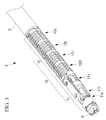
Fig. 3 is a partial perspective view showing a bending section of the endoscope inFig. 2 . - {
Fig. 4 }
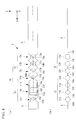
Figs. 4(a) and 4(b) are a simplified side view and a schematic side view, respectively, of the bending section inFig. 3 . - {
Fig. 5 }
Figs. 5(a) and 5(b) show a proximal-end joint group of the bending section inFig. 3 , whereFig. 5(a) is a side view showing the state where the proximal-end joint group is straight, andFig. 5(b) is a side view showing the state where the most distal joint is bent. - {
Fig. 6 }
Figs. 6(a) and 6(b) show the proximal-end joint group of the bending section inFig. 3 , whereFig. 6(a) is a side view showing the state where the proximal-end joint group is straight, andFig. 6(b) is a side view showing the state where the second-most distal joint is bent. - {
Fig. 7 }
Figs. 7(a) to 7(c) show the most proximal bending joint of the distal-end joint group of the bending section inFig. 3 , whereFig. 7(a) is a side view showing the state where the bending joint is straight,Fig. 7(b) is a side view showing the state where the bending joint is bent in one direction, andFig. 7(c) is a side view where the bending joint is bent in another direction. - {
Fig. 8 }
Figs. 8(a) to 8(c) show the second-most proximal bending joint of the distal-end joint group of the bending section inFig. 3 , whereFig. 8(a) is a side view showing the state where the bending joint is straight,Fig. 8(b) is a side view showing the state where the bending joint is bent in one direction, andFig. 8(c) is a side view where the bending joint is bent in another direction. - {
Fig. 9 }
Figs. 9(a) to 9(c) show the most distal bending joint of the distal-end joint group of the bending section inFig. 3 , whereFig. 9(a) is a side view showing the state where the bending joint is straight,Fig. 9(b) is a side view showing the state where the bending joint is bent in one direction, andFig. 9(c) is a side view where the bending joint is bent in another direction. - {
Fig. 10 }
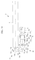
Fig. 10 is a simplified side view showing the state where the bending section of the endoscope inFig. 2 is bent through 180° by the proximal-end joint group of the bending section. - {
Fig. 11 }
Figs. 11(a) and 11(b) are a schematic plan view and a schematic side view, respectively, illustrating the translation of the tip of the endoscope inFig. 2 by the bending section. - {
Fig. 12 }
Fig. 12 is a schematic side view illustrating the linear translation of the tip of the endoscope inFig. 2 by the bending section. - {
Fig. 13 }
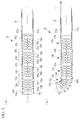
Figs. 13(a) and 13(b) illustrate how the bending section of the endoscope inFig. 2 is advanced and retracted like an inchworm, whereFig. 13(a) is a side view showing the state where the bending section is straight, andFig. 13(b) is a side view showing the state where the proximal-end joint group is contracted. - {
Fig. 14 }
Fig. 14(a) is a side view showing the state where the bending section of the endoscope inFig. 2 is inserted into a lumen, andFig. 14(b) is a side view showing the state where the bending section is fixed by the proximal-end joint group of the bending section. - {
Fig. 15 }
Figs. 15(a), 15(b), and 15(c) are schematic side views showing first, second, and third modifications, respectively, of the axial structure of the bending section of the endoscope inFig. 2 . - A manipulator and manipulator system according to an embodiment of the present invention will be described below with reference to the drawings.
- As shown in
Fig. 1 , the manipulator system according to this embodiment is an endoscope system 1 including amaster device 2 that is manipulated by a doctor (operator) A, aslave device 3 that is driven by inputs via themaster device 2, acontroller 4 that controls theslave device 3 based on the inputs to themaster device 2, and amonitor 25. - As shown in
Fig. 2 , theslave device 3 includes anendoscope 5 according to this embodiment for insertion into the lumen of a patient P and driveunits endoscope 5. - The manipulator according to this embodiment is the
endoscope 5, which is a flexible endoscope including a bendable flexibleelongated insertion part 7 that has an elongatedflexible section 8, atip 9 disposed at the distal end thereof, and abending section 10 disposed between thetip 9 and theflexible section 8. Although theendoscope 5 according to this embodiment is a flexible endoscope, it may instead be a rigid endoscope including an elongated rigid section. - As shown in
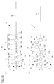
Fig. 3 , the bendingsection 10 includes a distal-endjoint group 11 and a proximal-endjoint group 12 for changing the position and orientation of thetip 9 relative to the distal end of theflexible section 8. The distal-endjoint group 11 and the proximal-endjoint group 12 are arranged in line in the longitudinal direction of theinsertion part 7.Fig. 4(a) is a simplified view of thebending section 10, andFig. 4(b) is a schematic view of thebending section 10. - The proximal-end
joint group 12 includes a plurality of bending joints, for example, four bending joints (proximal-end bending joints) 12a to 12d. Each of the bending joints 12a to 12d is disposed between two oflink members 13a to 13e such that the relative angle between any two of thelink members 13a to 13e is variable. - The bending joints 12a to 12d are independently bendable about
axes 14a to 14d, respectively, arranged parallel to each other (i.e., in the Y-axis direction) at intervals in the longitudinal direction of theinsertion part 7, i.e., in the longitudinal axis direction of thelink members 13a to 13e. For example, the bending joints 12a to 12d are configured to be bendable over a bending angle range of ±60° so that the entire proximal-endjoint group 12 is bendable through ±240°. Theaxes 14a to 14d do not necessarily have to extend parallel to each other, but may lined-up side-by-side in a manner that allows bending. - For example, as shown in
Figs. 5 and6 , each of the bending joints 12a to 12d includes a plurality of pieces, for example, fourpieces 15a to 15d, joined together so as to be pivotable relative to each other between two of thelink members 13a to 13e, and ends ofwires 16a extending through through-holes provided at ends of thepieces 15a to 15d are fixed to the mostdistal link member 13e. -
Fig. 5 illustrates the motion of the most distal bending joint 12d of the proximal-endjoint group 12. Twowires 16a are guided by twosheathes 17a extending in the longitudinal direction from the proximal end of theinsertion part 7 to thelink member 13d at the proximal end of the bending joint 12d and are fixed to thelink member 13e at the distal end of the bending joint 12d. By applying a tension F to one of thewires 16a, the most distal bending joint 12d, which is initially straight, as shown inFig. 5(a) , can be bent alone in one direction, as shown inFig. 5(b) . -
Fig. 6 illustrates the motion of the second-most distal bending joint 12c of the proximal-endjoint group 12. Twowires 16b are guided by two sheathes 17b extending in the longitudinal direction from the proximal end of theinsertion part 7 to thelink member 13c at the proximal end of the bending joint 12c and are fixed to thelink member 13d at the distal end of the bending joint 12c. By applying a tension to one of the wires 17b, the second-most distal bending joint 12c, which is initially straight, as shown inFig. 6(a) , can be bent alone in one direction, as shown inFig. 6(b) . - Although not illustrated, the third- and fourth-most distal bending joints 12b and 12a are configured in the same manner.
- The distal-end
joint group 11 includes a plurality of bending joints, for example, three bending joints (distal-end bending joints) 11a to 11c. Each of the bending joints 11a to 11c is disposed between two oflink members 13f to 13h such that the relative angle between any two of thelink members 13f to 13h is variable. - As shown in
Fig. 3 , the twoproximal bending joints link members 13f to 13h are pivotable aboutaxes axis 14d of the most distal bending joint 12d of the proximal-endjoint group 12 and the longitudinal axis of thelink members 13e to 13h (i.e., extending in the Z-axis direction). The most distal bending joint 11c is configured such that thetip 9 is pivotable about anaxis 14g extending perpendicular to a plane including theaxes link members 13e to 13h (i.e., extending in the Y-axis direction). Theaxes axis 14d and the longitudinal axis, but may cross the plane in any manner that allows bending. - As shown in
Figs. 7(a) to 7(c) , the most proximal bending joint 11a of the distal-endjoint group 11 is configured such that thedistal link member 13f is pivotable relative to theproximal link member 13e, for example, by applying a tension F towires 19a fixed at the ends thereof to apulley 18a fixed to thelink member 13f and pivotably coupled to thelink member 13e. There are twowires 19a fixed at the ends thereof to thepulley 18a such that thepulley 18a is rotatable in opposite directions by the tension F. - As shown in
Figs. 8(a) to 8(c) , the second-most proximal bending joint 11b of the distal-endjoint group 11 includes a proximal-end pulley 18b pivotably coupled to the twolink members end pulley 18c fixed to thedistal link member 13g and pivotably coupled to theproximal link member 13f, andcoupling links 20 coupling the twopulleys link member 13g is pivotable relative to thelink member 13f by applying a tension F towires 19b fixed at the ends thereof to the proximal-end pulley 18b. There are twowires 19b fixed at the ends thereof to the proximal-end pulley 18b such that the proximal-end pulley 18b is rotatable in opposite directions by the tension F. - As shown in
Figs. 9(a) to 9(c) , the most distal bending joint 11c of theinsertion part 7 is configured such that the twolink members axis 14g relative to each other and thelink member 13h is pivotable relative to thelink member 13g by applying a tension F towires 19c fixed at the ends thereof to thedistal link member 13g. - All of the
wires flexible section 8 toward the proximal end of theflexible section 8. - As shown in
Fig. 2 , thedrive units end drive unit 6a that drives the distal-endjoint group 11 and a proximal-end drive unit 6b that drives the proximal-endjoint group 12. Each of thedrive units flexible section 8 of theendoscope 5 via arelay 21. Thedrive units wires flexible section 8 toward the proximal end so that the proximal ends of thewires wires drive source 22 including an electric actuator, or a manually operated master for manual operation (not shown). - The actuators for the
drive sources 22 are, for example, linear actuators such as linear motors. When thedrive units drive units wires - When the
drive units drive units wires - The
relay 21 has aport 23 through which a surgical instrument is inserted into a forceps channel (not shown) extending in the longitudinal direction of theinsertion part 7 to the distal-end surface thereof. - As shown in
Fig. 1 , themaster device 2 is an input device having the same number of joints as thebending section 10 of theendoscope 5 and being geometrically similar thereto. The individual joints have detectors (not shown), such as encoders, that detect the bending angles thereof. When the doctor A grasps and moves the end of themaster device 2, the detectors detect the bending angles of the joints of themaster device 2 and output bending angle signals. - The
controller 4 controls thedrive units bending section 10 of theendoscope 5 are identical to the bending angles of the joints of themaster device 2 indicated by the bending angle signals output from themaster device 2. - The operation of the thus-configured
endoscope 5 and endoscope system 1 according to this exemplary embodiment will be described below. - For observation and treatment in the lumen of the patient P using the
endoscope 5 according to this embodiment, a manually operated master is attached only to the distal-end drive unit 6a that drives the distal-endjoint group 11 before the insertion of theendoscope 5 into the lumen. - The doctor A holds the
insertion part 7 with his or her right hand and inserts theendoscope 5 into the lumen in the same way as he or she does with a conventional endoscope while manipulating the manually operated master with his or her left hand. During this procedure, an image of the interior of the lumen is captured and displayed on themonitor 25 by operating theendoscope 5. The doctor A manipulates the manually operated master to drive the distal-endjoint group 11 while watching themonitor 25 and advances theinsertion part 7 through the lumen until thetip 9 of theendoscope 5 approaches the affected area. - In this state, no
drive source 22 or manually operated master is attached to the proximal-end drive unit 6b that drives the proximal-endjoint group 12; therefore, the proximal-endjoint group 12 moves passively in unison with the motion of the distal-endjoint group 11. This prevents the proximal-endjoint group 12 from interfering with the insertion motion. - When the
tip 9 of theinsertion part 7 approaches the affected area, the manually operated master is replaced with adrive source 22, anotherdrive source 22 is attached to the proximal-end drive unit 6b, and the doctor A manipulates themaster device 2. - Since the proximal-end
joint group 12 of theendoscope 5 according to this embodiment includes the fourbending joints 12a to 12d, which bend through a total of ±240°, the bendingsection 10 can be bent into a U-shape to direct the distal-end surface of theendoscope 5 toward the back, as shown inFig. 10 . After thebending section 10 is bent into a U-shape, there is a margin in the moving range of the bending joints 12a to 12d; therefore, thetip 9 of theinsertion part 7 can be advanced and retracted. This is advantageous in that the distal-end surface of theinsertion part 7 can be directed to a position suitable for observation or treatment even if the affected area is located toward the back in the insertion direction, for example, behind a fold in the lumen, rather than toward the front in the insertion direction. - The distal end of the
insertion part 7 of theendoscope 5 according to this embodiment can be turned through 180° only by the motion of the proximal-endjoint group 12. After the distal end of theinsertion part 7 is turned through 180°, the distal-end surface of theinsertion part 7 can be moved to any position three-dimensionally by the three bendingjoints 11a to 11c of the distal-endjoint group 11. As shown inFig. 11(a) , theendoscope 5 according to this embodiment allows thetip 9 to be translated in a direction perpendicular to the bending direction of the proximal-endjoint group 12 by the cooperative motion of the two bendingjoints joint group 11. As shown inFig. 11(b) , theendoscope 5 according to this embodiment also allows thetip 9 to be translated in the bending direction of the proximal-endjoint group 12 by the cooperative motion of the most distal bending joint 12d of the proximal-endjoint group 12 and the most distal bending joint 11c of the proximal-endjoint group 11. - That is, the
tip 9 can be translated while being maintained in the same orientation by setting the orientation of thetip 9 in two orthogonal directions using the two distal bending joints 11b and 11c of the distal-endjoint group 11 and canceling the pivoting of thetip 9 due to the two distal bending joints 11b and 11c by the cooperative motion of the twoproximal bending joints tip 9 and the inner wall of the lumen. - Since the proximal-end
joint group 12 in this embodiment has a bending angle of ±240°, there is a margin in the moving range after thetip 9 is turned through 180°; therefore, thetip 9 can be precisely translated. As shown inFig. 12 , thetip 9 can be translated along a straight path in the bending direction of the proximal-endjoint group 12 by the cooperative motion of all bendingjoints 12a to 12d of the proximal-endjoint group 12 and the bending joint 11c of the distal-endjoint group 11. - As shown in
Figs. 13(a) and 13(b) , when the proximal-endjoint group 12 is substantially straight, thetip 9 of theinsertion part 7 can be advanced and retracted by bending the twoperipheral bending joints bending joints 12a to 12d in different directions such that the bending joints 12a to 12d move like an inchworm. This allows the position of thetip 9 to be finely adjusted without manually inserting theinsertion part 7. - As shown in
Fig. 14 , after theinsertion part 7 is advanced through a lumen B to approach the affected area, the proximal-endjoint group 12 may be bent into a U-shape, as shown inFig. 14(a) , and thebent insertion part 7 may itself be pressed against the inner wall of the lumen B so as to expand the lumen B, as shown inFig. 14(b) . This allows theinsertion part 7 to be fixed relative to the lumen B and also ensures sufficient space for stable observation and treatment. - After the treatment is complete, the
endoscope 5 can be removed from the lumen B by separating thedrive units drive sources 22 to allow all bendingjoints 11a to 11c and 12a to 12d to move passively and by manually removing theinsertion part 7. - Although the
bending section 10 illustrated in this embodiment includes the distal-endjoint group 11, which is composed of the three bendingjoints 11a to 11c, and the proximal-endjoint group 12, which is composed of the fourbending joints 12a to 12d, this axial structure does not necessarily have to be used; other axial structures may be used, including those shown inFig. 15 . -
Fig. 15(a) shows a proximal-endjoint group 12 including fourbending joints 12a to 12d having the axes thereof in the Y-axis direction and fourbending joints 12e to 12h having the axes thereof in the Z-axis direction, rather than only the fourbending joints 12a to 12d having the axes thereof in the Y-axis direction, and these bending joints are arranged alternately in the longitudinal axis direction. This allows the proximal-endjoint group 12 to be bent through 180° or more in two axial directions. -
Fig. 15(b) shows a distal-endjoint group 11 including a bending joint 11d having the axis thereof in the Y-axis direction in addition to the three bendingjoints 11a to 11c. This allows thetip 9 to be translated while being maintained in the same orientation by the cooperative motion of the bending joints 11a to 11d that form the distal-endjoint group 11. -
Fig. 15(c) shows a distal-endjoint group 11 including fourbending joints 11a to 11d, as doesFig. 15(b) ; however, the bending joints 11c and 11d, which have the axes thereof in the Y-axis direction, and the bending joints 11a and 11b, which have the axes thereof in the Z-axis direction, are arranged alternately in the longitudinal axis direction. This distal-endjoint group 11 can move in the same way as that inFig. 15(b) . - Although the proximal-end
joint group 12 illustrated in this embodiment has a total moving range of ±240°, it does not necessarily have to have such a moving range; it may have a moving range of 180° or more in at least one direction. This allows thetip 9 to be turned through 180°. - The proximal-end
joint group 12 may include at least one bending joint in addition to a plurality of bending joints having a total moving range of 180° or more in at least one direction. This allows for a greater margin after thetip 9 is turned through 180°. - Although the joints illustrated in this embodiment are arranged at intervals with link members therebetween, the link members do not necessarily have to be used; the joints may be coupled together without link members therebetween. This allows for more bending.
- Although the manipulator and manipulator system illustrated as an example in this embodiment are the
endoscope 5 and the endoscope system 1, they do not necessarily have to be used for those applications; they may be used as a manipulator and a manipulator system for other applications, such as surgical instruments. -
- A doctor (operator)
- 1 endoscope system (manipulator system)
- 2 master device
- 3 slave device
- 4 controller
- 5 endoscope (manipulator)
- 6a distal-end drive unit (drive unit)
- 6b proximal-end drive unit (drive unit)
- 7 insertion part
- 9 tip
- 10 bending section (distal-end section)
- 11 distal-end joint group
- 11a, 11b bending joint (first distal-end bending joint)
- 11c bending joint (second distal-end bending joint)
- 12 proximal-end joint group
- 12a to 12h bending joint (proximal-end bending joint)
Claims (6)
- A manipulator comprising:a distal-end joint group and a proximal-end joint group that are arranged adjacent to each other in a distal-end section of an elongated insertion part in a longitudinal axis direction and that are configured to bend the distal-end section,the proximal-end joint group comprising a plurality of proximal-end bending joints bendable about axes that are lined-up side-by-side to bend the distal-end section through 180° or more,the distal-end joint group comprising a first distal-end bending joint disposed on a distal side of the proximal-end joint group and bendable about an axis perpendicular to a plane including the axes of the proximal-end bending joints and the longitudinal axis; and a second distal-end bending joint disposed in the longitudinal axis direction relative to the axis of the first distal-end bending joint and bendable about an axis that is lined-up side-by-side with the axes of the proximal-end bending joints.
- The manipulator according to Claim 1, wherein the proximal-end joint group comprises one or more proximal-end bending joints in addition to the proximal-end bending joints configured to bend the distal-end section through 180° or more.
- The manipulator according to Claim 1 or 2, wherein the proximal-end joint group comprises three or more proximal-end bending joints.
- The manipulator according to any one of Claims 1 to 3, wherein the distal-end joint group comprises two or more first distal-end bending joints.
- The manipulator according to any one of Claims 1 to 4, wherein the distal-end joint group comprises two or more second distal-end bending joints.
- A manipulator system comprising:a slave device comprising the manipulator according to any one of Claims 1 to 5 and a drive unit configured to drive the manipulator;a master device comprising a manipulating part configured to be manipulated by an operator; anda controller configured to control the drive unit of the slave device based on an input signal input via the manipulating part of the master device.
Applications Claiming Priority (2)
| Application Number | Priority Date | Filing Date | Title |
|---|---|---|---|
| JP2013154468A JP6137976B2 (en) | 2013-07-25 | 2013-07-25 | Manipulator system |
| PCT/JP2014/067498 WO2015012066A1 (en) | 2013-07-25 | 2014-07-01 | Manipulator and manipulator system |
Publications (2)
| Publication Number | Publication Date |
|---|---|
| EP3025634A1 true EP3025634A1 (en) | 2016-06-01 |
| EP3025634A4 EP3025634A4 (en) | 2017-04-05 |
Family
ID=52393117
Family Applications (1)
| Application Number | Title | Priority Date | Filing Date |
|---|---|---|---|
| EP14829651.0A Withdrawn EP3025634A4 (en) | 2013-07-25 | 2014-07-01 | Manipulator and manipulator system |
Country Status (5)
| Country | Link |
|---|---|
| US (1) | US10085813B2 (en) |
| EP (1) | EP3025634A4 (en) |
| JP (1) | JP6137976B2 (en) |
| CN (1) | CN105392413B (en) |
| WO (1) | WO2015012066A1 (en) |
Families Citing this family (7)
| Publication number | Priority date | Publication date | Assignee | Title |
|---|---|---|---|---|
| JP6556347B2 (en) * | 2016-05-27 | 2019-08-07 | オリンパス株式会社 | MEDICAL MANIPULATOR AND METHOD OF OPERATING MEDICAL MANIPULATOR |
| US11103992B2 (en) | 2017-02-28 | 2021-08-31 | Canon Kabushiki Kaisha | Apparatus of continuum robot |
| JP2019093119A (en) * | 2017-10-05 | 2019-06-20 | キヤノン ユーエスエイ, インコーポレイテッドCanon U.S.A., Inc | Medical continuum robot with multiple bendable sections |
| CN110269682B (en) * | 2018-03-14 | 2020-09-01 | 深圳市精锋医疗科技有限公司 | Connecting assembly, operating arm, slave operating equipment and surgical robot |
| CN110269696B (en) * | 2018-03-14 | 2020-09-22 | 深圳市精锋医疗科技有限公司 | Connecting components, operating arms, slave operating equipment and surgical robots |
| US11547286B2 (en) * | 2020-01-22 | 2023-01-10 | Brio13Inv. LLC | Stylet assembly |
| JP2023130101A (en) * | 2022-03-07 | 2023-09-20 | キヤノン株式会社 | medical equipment |
Family Cites Families (23)
| Publication number | Priority date | Publication date | Assignee | Title |
|---|---|---|---|---|
| JPH0355184A (en) * | 1989-07-20 | 1991-03-08 | Tokico Ltd | industrial robot |
| JPH05199982A (en) * | 1992-01-24 | 1993-08-10 | Olympus Optical Co Ltd | In-tube disposing device |
| JP3322356B2 (en) * | 1993-01-29 | 2002-09-09 | オリンパス光学工業株式会社 | Flexible tube |
| JP3473834B2 (en) * | 1999-11-29 | 2003-12-08 | 株式会社安川電機 | Robot control device |
| JP3776767B2 (en) * | 2000-10-02 | 2006-05-17 | オリンパス株式会社 | Endoscope |
| US20040249367A1 (en) | 2003-01-15 | 2004-12-09 | Usgi Medical Corp. | Endoluminal tool deployment system |
| US20060041188A1 (en) * | 2003-03-25 | 2006-02-23 | Dirusso Carlo A | Flexible endoscope |
| JP4503985B2 (en) * | 2003-11-07 | 2010-07-14 | オリンパス株式会社 | Medical control device |
| JP2007054400A (en) * | 2005-08-25 | 2007-03-08 | Olympus Medical Systems Corp | Endoscope |
| US7930065B2 (en) * | 2005-12-30 | 2011-04-19 | Intuitive Surgical Operations, Inc. | Robotic surgery system including position sensors using fiber bragg gratings |
| US20080064927A1 (en) | 2006-06-13 | 2008-03-13 | Intuitive Surgical, Inc. | Minimally invasrive surgery guide tube |
| US8551076B2 (en) | 2006-06-13 | 2013-10-08 | Intuitive Surgical Operations, Inc. | Retrograde instrument |
| US9055906B2 (en) * | 2006-06-14 | 2015-06-16 | Intuitive Surgical Operations, Inc. | In-vivo visualization systems |
| JP4855867B2 (en) * | 2006-08-22 | 2012-01-18 | オリンパスメディカルシステムズ株式会社 | Endoscope |
| JP4821516B2 (en) * | 2006-08-31 | 2011-11-24 | 旭光電機株式会社 | Articulated structure |
| US20080208001A1 (en) * | 2007-02-26 | 2008-08-28 | Ron Hadani | Conforming endoscope |
| JP2008237812A (en) * | 2007-03-29 | 2008-10-09 | Olympus Medical Systems Corp | Multi-joint bending mechanism and medical device with multi-joint bending mechanism |
| JP5197980B2 (en) | 2007-03-29 | 2013-05-15 | オリンパスメディカルシステムズ株式会社 | Multi-joint bending mechanism and medical device with multi-joint bending mechanism |
| WO2012014532A1 (en) * | 2010-07-28 | 2012-02-02 | オリンパスメディカルシステムズ株式会社 | Endoscope, and method for inserting and bending the endoscope |
| JP2011118924A (en) * | 2011-02-17 | 2011-06-16 | Kyokko Denki Kk | Articulated structure, and wearing tool, system and human machine interface using the same |
| JP5506724B2 (en) | 2011-03-18 | 2014-05-28 | 富士フイルム株式会社 | Endoscope device |
| US9456735B2 (en) * | 2012-09-27 | 2016-10-04 | Shahinian Karnig Hrayr | Multi-angle rear-viewing endoscope and method of operation thereof |
| JP6129087B2 (en) * | 2014-01-14 | 2017-05-17 | オリンパス株式会社 | Joint mechanism, manipulator and manipulator system |
-
2013
- 2013-07-25 JP JP2013154468A patent/JP6137976B2/en active Active
-
2014
- 2014-07-01 EP EP14829651.0A patent/EP3025634A4/en not_active Withdrawn
- 2014-07-01 WO PCT/JP2014/067498 patent/WO2015012066A1/en not_active Ceased
- 2014-07-01 CN CN201480040977.4A patent/CN105392413B/en active Active
-
2016
- 2016-01-21 US US15/002,515 patent/US10085813B2/en active Active
Also Published As
| Publication number | Publication date |
|---|---|
| JP2015023951A (en) | 2015-02-05 |
| CN105392413B (en) | 2019-09-24 |
| WO2015012066A1 (en) | 2015-01-29 |
| JP6137976B2 (en) | 2017-05-31 |
| US10085813B2 (en) | 2018-10-02 |
| EP3025634A4 (en) | 2017-04-05 |
| CN105392413A (en) | 2016-03-09 |
| US20160135913A1 (en) | 2016-05-19 |
Similar Documents
| Publication | Publication Date | Title |
|---|---|---|
| US10085813B2 (en) | Manipulator and manipulator system | |
| JP7335382B2 (en) | Actuation of Push/Pull Surgical Instrument End Effector Using Flexible Tension Member | |
| US11497387B2 (en) | Joint mechanism, manipulator, and manipulator system | |
| US8377045B2 (en) | Extendable suction surface for bracing medial devices during robotically assisted medical procedures | |
| EP3025674B1 (en) | Therapeutic manipulator and manipulator system | |
| EP2706932B1 (en) | A surgical device | |
| EP2881048A1 (en) | Medical manipulator | |
| CN106231983B (en) | Treatment apparatus adapter, endoscope and endoscopic system | |
| EP4059454A1 (en) | Surgical device for grasping and shearing | |
| JP6300801B2 (en) | Medical manipulator and method for controlling medical manipulator | |
| KR101750628B1 (en) | An apparatus for surgery comprising a surgical arm attached to the endoscope and a surgery system comprising thereof | |
| US20110178367A1 (en) | Endoscopic device with end effector mechanism | |
| CN102641150A (en) | Surgical endoscope and process for exchanging surgical tools in a surgical endoscope | |
| EP3031382B1 (en) | Medical device | |
| JP7096393B2 (en) | Surgical system and support device | |
| WO2024058098A1 (en) | Movable long structure and method for manipulating same, medical system, tool, robot and method for operating same, manipulator, flexible endoscope, and steering catheter | |
| KR101063281B1 (en) | Single Port Surgical Adapter | |
| US9687270B2 (en) | Instrument system for minimally invasive surgery in single port technology | |
| LAM et al. | Implementation of a Novel Handheld Endoscopic Operation Platform (EndoGRASP) | |
| CN108852515B (en) | Slave operation device for single incision surgery and surgical robot |
Legal Events
| Date | Code | Title | Description |
|---|---|---|---|
| PUAI | Public reference made under article 153(3) epc to a published international application that has entered the european phase |
Free format text: ORIGINAL CODE: 0009012 |
|
| 17P | Request for examination filed |
Effective date: 20160210 |
|
| AK | Designated contracting states |
Kind code of ref document: A1 Designated state(s): AL AT BE BG CH CY CZ DE DK EE ES FI FR GB GR HR HU IE IS IT LI LT LU LV MC MK MT NL NO PL PT RO RS SE SI SK SM TR |
|
| AX | Request for extension of the european patent |
Extension state: BA ME |
|
| RAP1 | Party data changed (applicant data changed or rights of an application transferred) |
Owner name: OLYMPUS CORPORATION |
|
| RAP1 | Party data changed (applicant data changed or rights of an application transferred) |
Owner name: OLYMPUS CORPORATION |
|
| RIN1 | Information on inventor provided before grant (corrected) |
Inventor name: NAKAYAMA, SHINGO Inventor name: KISHI, KOSUKE |
|
| DAX | Request for extension of the european patent (deleted) | ||
| RIN1 | Information on inventor provided before grant (corrected) |
Inventor name: NAKAYAMA, SHINGO Inventor name: KISHI, KOSUKE |
|
| A4 | Supplementary search report drawn up and despatched |
Effective date: 20170307 |
|
| RIC1 | Information provided on ipc code assigned before grant |
Ipc: A61B 1/00 20060101AFI20170301BHEP Ipc: G02B 23/24 20060101ALI20170301BHEP |
|
| STAA | Information on the status of an ep patent application or granted ep patent |
Free format text: STATUS: EXAMINATION IS IN PROGRESS |
|
| 17Q | First examination report despatched |
Effective date: 20200428 |
|
| STAA | Information on the status of an ep patent application or granted ep patent |
Free format text: STATUS: THE APPLICATION IS DEEMED TO BE WITHDRAWN |
|
| 18D | Application deemed to be withdrawn |
Effective date: 20200909 |