EP3025613A1 - Piston structure of pumping-type cosmetic container - Google Patents
Piston structure of pumping-type cosmetic container Download PDFInfo
- Publication number
- EP3025613A1 EP3025613A1 EP14829808.6A EP14829808A EP3025613A1 EP 3025613 A1 EP3025613 A1 EP 3025613A1 EP 14829808 A EP14829808 A EP 14829808A EP 3025613 A1 EP3025613 A1 EP 3025613A1
- Authority
- EP
- European Patent Office
- Prior art keywords
- piston
- contents
- pumping
- pistons
- type cosmetic
- Prior art date
- Legal status (The legal status is an assumption and is not a legal conclusion. Google has not performed a legal analysis and makes no representation as to the accuracy of the status listed.)
- Withdrawn
Links
Images



Classifications
-
- A—HUMAN NECESSITIES
- A45—HAND OR TRAVELLING ARTICLES
- A45D—HAIRDRESSING OR SHAVING EQUIPMENT; EQUIPMENT FOR COSMETICS OR COSMETIC TREATMENTS, e.g. FOR MANICURING OR PEDICURING
- A45D40/00—Casings or accessories specially adapted for storing or handling solid or pasty toiletry or cosmetic substances, e.g. shaving soaps or lipsticks
- A45D40/0068—Jars
- A45D40/0075—Jars with dispensing means
-
- A—HUMAN NECESSITIES
- A45—HAND OR TRAVELLING ARTICLES
- A45D—HAIRDRESSING OR SHAVING EQUIPMENT; EQUIPMENT FOR COSMETICS OR COSMETIC TREATMENTS, e.g. FOR MANICURING OR PEDICURING
- A45D34/00—Containers or accessories specially adapted for handling liquid toiletry or cosmetic substances, e.g. perfumes
-
- B—PERFORMING OPERATIONS; TRANSPORTING
- B05—SPRAYING OR ATOMISING IN GENERAL; APPLYING FLUENT MATERIALS TO SURFACES, IN GENERAL
- B05B—SPRAYING APPARATUS; ATOMISING APPARATUS; NOZZLES
- B05B11/00—Single-unit hand-held apparatus in which flow of contents is produced by the muscular force of the operator at the moment of use
- B05B11/01—Single-unit hand-held apparatus in which flow of contents is produced by the muscular force of the operator at the moment of use characterised by the means producing the flow
- B05B11/02—Membranes or pistons acting on the contents inside the container, e.g. follower pistons
- B05B11/028—Pistons separating the content remaining in the container from the atmospheric air to compensate underpressure inside the container
-
- B—PERFORMING OPERATIONS; TRANSPORTING
- B05—SPRAYING OR ATOMISING IN GENERAL; APPLYING FLUENT MATERIALS TO SURFACES, IN GENERAL
- B05B—SPRAYING APPARATUS; ATOMISING APPARATUS; NOZZLES
- B05B11/00—Single-unit hand-held apparatus in which flow of contents is produced by the muscular force of the operator at the moment of use
- B05B11/01—Single-unit hand-held apparatus in which flow of contents is produced by the muscular force of the operator at the moment of use characterised by the means producing the flow
- B05B11/10—Pump arrangements for transferring the contents from the container to a pump chamber by a sucking effect and forcing the contents out through the dispensing nozzle
- B05B11/1001—Piston pumps
- B05B11/1023—Piston pumps having an outlet valve opened by deformation or displacement of the piston relative to its actuating stem
-
- B—PERFORMING OPERATIONS; TRANSPORTING
- B05—SPRAYING OR ATOMISING IN GENERAL; APPLYING FLUENT MATERIALS TO SURFACES, IN GENERAL
- B05B—SPRAYING APPARATUS; ATOMISING APPARATUS; NOZZLES
- B05B11/00—Single-unit hand-held apparatus in which flow of contents is produced by the muscular force of the operator at the moment of use
- B05B11/01—Single-unit hand-held apparatus in which flow of contents is produced by the muscular force of the operator at the moment of use characterised by the means producing the flow
- B05B11/10—Pump arrangements for transferring the contents from the container to a pump chamber by a sucking effect and forcing the contents out through the dispensing nozzle
- B05B11/1028—Pumps having a pumping chamber with a deformable wall
-
- B—PERFORMING OPERATIONS; TRANSPORTING
- B05—SPRAYING OR ATOMISING IN GENERAL; APPLYING FLUENT MATERIALS TO SURFACES, IN GENERAL
- B05C—APPARATUS FOR APPLYING FLUENT MATERIALS TO SURFACES, IN GENERAL
- B05C5/00—Apparatus in which liquid or other fluent material is projected, poured or allowed to flow on to the surface of the work
- B05C5/02—Apparatus in which liquid or other fluent material is projected, poured or allowed to flow on to the surface of the work the liquid or other fluent material being discharged through an outlet orifice by pressure, e.g. from an outlet device in contact or almost in contact, with the work
-
- A—HUMAN NECESSITIES
- A45—HAND OR TRAVELLING ARTICLES
- A45D—HAIRDRESSING OR SHAVING EQUIPMENT; EQUIPMENT FOR COSMETICS OR COSMETIC TREATMENTS, e.g. FOR MANICURING OR PEDICURING
- A45D2200/00—Details not otherwise provided for in A45D
- A45D2200/05—Details of containers
- A45D2200/054—Means for supplying liquid to the outlet of the container
- A45D2200/055—Piston or plunger for supplying the liquid to the applicator
-
- A—HUMAN NECESSITIES
- A45—HAND OR TRAVELLING ARTICLES
- A45D—HAIRDRESSING OR SHAVING EQUIPMENT; EQUIPMENT FOR COSMETICS OR COSMETIC TREATMENTS, e.g. FOR MANICURING OR PEDICURING
- A45D2200/00—Details not otherwise provided for in A45D
- A45D2200/05—Details of containers
- A45D2200/054—Means for supplying liquid to the outlet of the container
- A45D2200/056—Reciprocating pumps, i.e. with variable volume chamber wherein pressure and vacuum are alternately generated
-
- B—PERFORMING OPERATIONS; TRANSPORTING
- B05—SPRAYING OR ATOMISING IN GENERAL; APPLYING FLUENT MATERIALS TO SURFACES, IN GENERAL
- B05B—SPRAYING APPARATUS; ATOMISING APPARATUS; NOZZLES
- B05B11/00—Single-unit hand-held apparatus in which flow of contents is produced by the muscular force of the operator at the moment of use
- B05B11/0005—Components or details
- B05B11/0062—Outlet valves actuated by the pressure of the fluid to be sprayed
- B05B11/007—Outlet valves actuated by the pressure of the fluid to be sprayed being opened by deformation of a sealing element made of resiliently deformable material, e.g. flaps, skirts, duck-bill valves
-
- B—PERFORMING OPERATIONS; TRANSPORTING
- B05—SPRAYING OR ATOMISING IN GENERAL; APPLYING FLUENT MATERIALS TO SURFACES, IN GENERAL
- B05B—SPRAYING APPARATUS; ATOMISING APPARATUS; NOZZLES
- B05B11/00—Single-unit hand-held apparatus in which flow of contents is produced by the muscular force of the operator at the moment of use
- B05B11/0005—Components or details
- B05B11/0062—Outlet valves actuated by the pressure of the fluid to be sprayed
- B05B11/0072—A valve member forming part of an outlet opening
-
- B—PERFORMING OPERATIONS; TRANSPORTING
- B05—SPRAYING OR ATOMISING IN GENERAL; APPLYING FLUENT MATERIALS TO SURFACES, IN GENERAL
- B05B—SPRAYING APPARATUS; ATOMISING APPARATUS; NOZZLES
- B05B11/00—Single-unit hand-held apparatus in which flow of contents is produced by the muscular force of the operator at the moment of use
- B05B11/01—Single-unit hand-held apparatus in which flow of contents is produced by the muscular force of the operator at the moment of use characterised by the means producing the flow
- B05B11/10—Pump arrangements for transferring the contents from the container to a pump chamber by a sucking effect and forcing the contents out through the dispensing nozzle
- B05B11/1001—Piston pumps
- B05B11/1023—Piston pumps having an outlet valve opened by deformation or displacement of the piston relative to its actuating stem
- B05B11/1025—Piston pumps having an outlet valve opened by deformation or displacement of the piston relative to its actuating stem a spring urging the outlet valve in its closed position
-
- B—PERFORMING OPERATIONS; TRANSPORTING
- B05—SPRAYING OR ATOMISING IN GENERAL; APPLYING FLUENT MATERIALS TO SURFACES, IN GENERAL
- B05B—SPRAYING APPARATUS; ATOMISING APPARATUS; NOZZLES
- B05B11/00—Single-unit hand-held apparatus in which flow of contents is produced by the muscular force of the operator at the moment of use
- B05B11/01—Single-unit hand-held apparatus in which flow of contents is produced by the muscular force of the operator at the moment of use characterised by the means producing the flow
- B05B11/10—Pump arrangements for transferring the contents from the container to a pump chamber by a sucking effect and forcing the contents out through the dispensing nozzle
- B05B11/1042—Components or details
- B05B11/1073—Springs
- B05B11/1074—Springs located outside pump chambers
Definitions
- the present invention relates to a piston structure of a pumping-type cosmetic container, and more particularly, to a piston structure of a pumping-type cosmetic container including two pistons which are in close contact with an inner wall of a container body, overlapping each other, wherein, during a pumping operation, a first piston firstly ascends to a predetermined section, and then lifts up a second piston located under the first piston such that the first and the second pistons ascend together, and thus the volume taken up by the pistons can be reduced when contents are initially filled while a thickness for a normal operation of the pistons is maintained, so that relatively more contents can be filled in the same container having the same volume.
- a pumping-type cosmetic container includes: a container body for storing contents; a piston which is installed at an inner lower portion of the container body and ascends as the contents are discharged; and a pumping means coupled to an upper portion of the container body and discharging the contents stored in the container body by a pumping operation.
- the piston installed in the pumping-type cosmetic container like the above is required to allow a sidewall portion thereof in contact with an inner wall of the container body to secure a thickness thicker than a predetermined height in order to prevent a phenomenon in which the piston is upside down due to an internal pressure of the container body during an ascending operation of the piston.
- the piston takes up a lot of inner space of the container body due to the thickness of the piston for a normal operation, there is a problem in that the contents may not be filled by the space taken up by the piston.
- Korean utility model registration No. 20-0235847 entitled “Piston of dispenser container” was proposed by the applicant in order to resolve the problem.
- a dispenser container includes: a container part 10 for storing contents; a piston 20 which is installed in the container part 10 and ascends as the contents are discharged; and a pumping part 30 coupled to an upper end portion of the container part 10, for discharging the contents to the outside
- the piston 20 includes: an inner piston 21 formed in a tubular shape and having an opened upper surface, a bottom 23, and a sidewall 22, the inner piston 21 having locking jaws 24 and 25 each of which is formed on outer circumferential surfaces of an upper end portion and a lower end portion thereof; and an outer piston 26 liftably coupled to the outer circumferential surface of the inner piston 21, the outer piston 26 ascending while an outer circumferential surface thereof is in close contact with an inner wall surface of the container part 10, and wherein the outer piston 26 is positioned at a lower end portion of the inner piston 21 to reduce unused space of the container part 10 while the contents are filled in the container part 10, and the outer piston 26 ascends to the upper end portion of the inner piston 21 to reduce a
- the utility model registration having the above-described configuration is configured such that the inner piston 21 is formed in the shape of a hollow cylinder having an opened upper portion to fill the contents therein, and thus relatively more contents may be filled in the container having the same volume, and the outer piston 26 ascends to the upper end portion of the inner piston 21 when the contents are completely discharged such that the remaining amount of the contents is reduced.
- the present invention is devised to solve the problems described above, and an object of the present invention is to provide a piston structure of a pumping-type cosmetic container, the piston structure including two pistons which closely contact an inner wall of a container body and overlap each other, wherein, during a pumping operation, a first piston firstly ascends by a predetermined section, and then a second piston located thereunder is lifted up such that the first and second pistons ascend together, and thus the volume taken up by the pistons can be reduced when contents are initially filled while a thickness for a normal operation of the pistons is maintained, so that relatively more contents can be filled in the same container having the same volume.
- a piston structure of a pumping-type cosmetic container according to the present invention the pumping-type cosmetic container including a piston which is installed inside a container body receiving contents therein and ascends as the contents are consumed by a pumping operation of a pumping means, is characterized in that:
- the piston includes a first piston having a hollow cavity, and a second piston having a closed upper end portion and liftably coupled to the hollow cavity, wherein the second piston is positioned overlapping the first piston when the contents are initially filled, the second piston is configured to first ascend independently as the contents are consumed and to then lift the first piston such that the first and second pistons ascend together, and the first and second pistons are configured to ascend while the first and second pistons are in close contact with an inner wall of the container body.
- the piston structure is characterized in that a locking jaw is formed on an inner upper portion of the first piston to surround an inner circumferential surface of the first piston such that the first and second pistons ascend together while being in contact with each other.
- the piston structure is characterized in that a coupling portion which is liftably coupled to the hollow cavity of the first piston is provided to a lower central portion of the second piston, wherein the coupling portion includes a locking protrusion formed on a lower outer circumferential surface thereof such that the first and second pistons ascend together while the locking protrusion is in contact with the locking jaw.
- a first piston firstly ascends to a predetermined section by a pumping operation and thus a second piston located thereunder is then lifted up such that the first and the second pistons ascend together.
- FIG. 1 is an exploded perspective view illustrating constituents of a piston structure of a pumping-type cosmetic container according to a preferred embodiment of the present invention
- FIG. 2 is a cross-sectional view illustrating a coupled piston structure of a pumping-type cosmetic container according to a preferred embodiment of the present invention
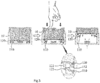
- FIGS. 3 and 4 are schematic diagrams illustrating operations of a piston installed in a pumping-type cosmetic container according to a preferred embodiment of the present invention.
- a piston 100 of a pumping-type cosmetic container is installed inside a container body 10 in which contents are received, and includes a first piston 110 and a second piston 120, the piston 100 being configured to ascend as the contents are consumed.
- the first piston 110 is in close contact with an inner wall of the container body 10 such that the first piston 110 may ascend together with the second piston 120 as the second piston 120 which will be described below ascends, and a hollow cavity 111 is formed such that a coupling portion of the second piston 120 is coupled thereto.
- the first piston 110 is characterized by including a locking jaw 112 formed on an inner upper portion thereof to surround an inner circumferential surface such that the first piston 110 may ascend together with the second piston 120 while the first piston is in close contact with the second piston, and a locking protrusion 122 of the second piston 120 is configured to be in contact with a lower end of the locking jaw 112 as the second piston 120 ascends such that the first piston 110 possibly ascends together with the second piston 120 as the second piston 120 ascends.
- the second piston 120 is located in close contact with the inner wall of the container body 10, is liftably coupled to the hollow cavity 111, and has a closed upper end portion, and in the present invention, the second piston 120 is characterized in that the second piston 120 is located overlapping the first piston 110 when the contents are initially filled, then the second piston 120 firstly ascends independently as the contents are consumed, and thus the first piston 110 is lifted up such that the first and the second pistons 110 and 120 ascend together.
- a coupling portion 121 which is liftably coupled to the hollow cavity 111 of the first piston 110 is provided to a lower central portion of the second piston 120, and a locking protrusion 122 is formed on an outer circumferential surface of the coupling portion 121 such that the locking protrusion 122 is in contact with the lower section of the locking jaw 112 while the second piston 120 ascends, and thus the second piston 120 and the first piston 110 may ascend together by the locking protrusion.
- FIGS. 3 and 4 are schematic diagrams illustrating operations of the piston installed in the pumping-type cosmetic container according to a preferred embodiment of the present invention.
- the piston installed in the pumping-type cosmetic container is configured such that the first piston 110 and the second piston 120 are located overlapping each other after the contents are initially filled, and when a user performs a pumping operation using a pumping means provided on an upper portion of the container body 10, the second piston 120 firstly ascends independently until the locking protrusion 122 of the second piston 120 contacts the locking jaw 112 of the first piston 110, and the second piston 120 then ascends together with the first piston 110 by lifting the first piston 110.
- the piston 100 installed inside the container body 10 is configured to include the first and the second pistons 110 and 120, wherein the first and the second pistons 110 and 120 are located overlapping each other when the contents are initially filled such that the thickness of the piston is made thin, thus the volume taken up by the piston may be reduced, and thus relatively more contents can be filled in the same container having the same volume, and also the first piston firstly ascends to a predetermined section and then lifts up the second piston provided thereunder such that the first and the second pistons ascend together, and thus a thickness for a normal operation of the pistons can be maintained.
Landscapes
- Containers And Packaging Bodies Having A Special Means To Remove Contents (AREA)
- Closures For Containers (AREA)
Abstract
Description
- The present invention relates to a piston structure of a pumping-type cosmetic container, and more particularly, to a piston structure of a pumping-type cosmetic container including two pistons which are in close contact with an inner wall of a container body, overlapping each other, wherein, during a pumping operation, a first piston firstly ascends to a predetermined section, and then lifts up a second piston located under the first piston such that the first and the second pistons ascend together, and thus the volume taken up by the pistons can be reduced when contents are initially filled while a thickness for a normal operation of the pistons is maintained, so that relatively more contents can be filled in the same container having the same volume.
- In general, a pumping-type cosmetic container includes: a container body for storing contents; a piston which is installed at an inner lower portion of the container body and ascends as the contents are discharged; and a pumping means coupled to an upper portion of the container body and discharging the contents stored in the container body by a pumping operation.
- The piston installed in the pumping-type cosmetic container like the above is required to allow a sidewall portion thereof in contact with an inner wall of the container body to secure a thickness thicker than a predetermined height in order to prevent a phenomenon in which the piston is upside down due to an internal pressure of the container body during an ascending operation of the piston. However, since the piston takes up a lot of inner space of the container body due to the thickness of the piston for a normal operation, there is a problem in that the contents may not be filled by the space taken up by the piston.
- Korean utility model registration No.
20-0235847 - The utility model registration is characterized in that a dispenser container includes: a
container part 10 for storing contents; a piston 20 which is installed in thecontainer part 10 and ascends as the contents are discharged; and a pumping part 30 coupled to an upper end portion of thecontainer part 10, for discharging the contents to the outside, wherein the piston 20 includes: an inner piston 21 formed in a tubular shape and having an opened upper surface, a bottom 23, and a sidewall 22, the inner piston 21 having locking jaws 24 and 25 each of which is formed on outer circumferential surfaces of an upper end portion and a lower end portion thereof; and an outer piston 26 liftably coupled to the outer circumferential surface of the inner piston 21, the outer piston 26 ascending while an outer circumferential surface thereof is in close contact with an inner wall surface of thecontainer part 10, and wherein the outer piston 26 is positioned at a lower end portion of the inner piston 21 to reduce unused space of thecontainer part 10 while the contents are filled in thecontainer part 10, and the outer piston 26 ascends to the upper end portion of the inner piston 21 to reduce a remaining amount of the contents after the contents are completely discharged. - The utility model registration having the above-described configuration is configured such that the inner piston 21 is formed in the shape of a hollow cylinder having an opened upper portion to fill the contents therein, and thus relatively more contents may be filled in the container having the same volume, and the outer piston 26 ascends to the upper end portion of the inner piston 21 when the contents are completely discharged such that the remaining amount of the contents is reduced.
- However, since the utility model registration employs a structure in which the bottom 23 of the inner piston 21 partially contacts the lower portion of the pumping unit 30 during the ascending of the piston 20 due to consumption of the contents, the discharge of the contents by the pumping operation is not smoothly performed within a section in which the outer piston 25 independently ascends, and thus there was a problem in that wasted unused contents still occurred.
- Thus, there was a problem in that even though it was possible to fill a relatively larger amount of contents in a container having the same volume, there was little difference in the amount of contents that users could substantially use up.
- The present invention is devised to solve the problems described above, and an object of the present invention is to provide a piston structure of a pumping-type cosmetic container, the piston structure including two pistons which closely contact an inner wall of a container body and overlap each other, wherein, during a pumping operation, a first piston firstly ascends by a predetermined section, and then a second piston located thereunder is lifted up such that the first and second pistons ascend together, and thus the volume taken up by the pistons can be reduced when contents are initially filled while a thickness for a normal operation of the pistons is maintained, so that relatively more contents can be filled in the same container having the same volume.
- To solve the above-described problems, a piston structure of a pumping-type cosmetic container according to the present invention, the pumping-type cosmetic container including a piston which is installed inside a container body receiving contents therein and ascends as the contents are consumed by a pumping operation of a pumping means, is characterized in that:
- the piston includes a first piston having a hollow cavity, and a second piston having a closed upper end portion and liftably coupled to the hollow cavity, wherein the second piston is positioned overlapping the first piston when the contents are initially filled, the second piston is configured to first ascend independently as the contents are consumed and to then lift the first piston such that the first and second pistons ascend together, and the first and second pistons are configured to ascend while the first and second pistons are in close contact with an inner wall of the container body.
- Further, the piston structure is characterized in that a locking jaw is formed on an inner upper portion of the first piston to surround an inner circumferential surface of the first piston such that the first and second pistons ascend together while being in contact with each other.
- Furthermore, the piston structure is characterized in that a coupling portion which is liftably coupled to the hollow cavity of the first piston is provided to a lower central portion of the second piston, wherein the coupling portion includes a locking protrusion formed on a lower outer circumferential surface thereof such that the first and second pistons ascend together while the locking protrusion is in contact with the locking jaw.
- As described above, according to the present invention, in two pistons which are in close contact with an inner wall of a container body and overlap each other, a first piston firstly ascends to a predetermined section by a pumping operation and thus a second piston located thereunder is then lifted up such that the first and the second pistons ascend together. Thus, since the volume taken up by the pistons can be reduced when contents are initially filled while a thickness for a normal operation of the pistons is maintained, it is advantageous that relatively more contents can be filled in the same container having the same volume.
-
-
FIG. 1 is an exploded perspective view illustrating elements of a piston structure of a pumping-type cosmetic container according to a preferred embodiment of the present invention. -
FIG. 2 is a cross-sectional view illustrating a coupled piston structure of a pumping-type cosmetic container according to a preferred embodiment of the present invention. -
FIGS. 3 and4 are schematic diagrams illustrating operations of a piston installed in a pumping-type cosmetic container according to a preferred embodiment of the present invention. - Hereinafter, the present invention will be described in detail with reference to the drawings. Like reference numerals refer to like elements throughout.
-
FIG. 1 is an exploded perspective view illustrating constituents of a piston structure of a pumping-type cosmetic container according to a preferred embodiment of the present invention,FIG. 2 is a cross-sectional view illustrating a coupled piston structure of a pumping-type cosmetic container according to a preferred embodiment of the present invention, andFIGS. 3 and4 are schematic diagrams illustrating operations of a piston installed in a pumping-type cosmetic container according to a preferred embodiment of the present invention. - Referring to
FIGS. 1 to 4 , apiston 100 of a pumping-type cosmetic container according to a preferred embodiment of the present invention is installed inside acontainer body 10 in which contents are received, and includes afirst piston 110 and asecond piston 120, thepiston 100 being configured to ascend as the contents are consumed. - The
first piston 110 is in close contact with an inner wall of thecontainer body 10 such that thefirst piston 110 may ascend together with thesecond piston 120 as thesecond piston 120 which will be described below ascends, and ahollow cavity 111 is formed such that a coupling portion of thesecond piston 120 is coupled thereto. - In the present invention, the
first piston 110 is characterized by including alocking jaw 112 formed on an inner upper portion thereof to surround an inner circumferential surface such that thefirst piston 110 may ascend together with thesecond piston 120 while the first piston is in close contact with the second piston, and alocking protrusion 122 of thesecond piston 120 is configured to be in contact with a lower end of thelocking jaw 112 as thesecond piston 120 ascends such that thefirst piston 110 possibly ascends together with thesecond piston 120 as thesecond piston 120 ascends. - The
second piston 120 is located in close contact with the inner wall of thecontainer body 10, is liftably coupled to thehollow cavity 111, and has a closed upper end portion, and in the present invention, thesecond piston 120 is characterized in that thesecond piston 120 is located overlapping thefirst piston 110 when the contents are initially filled, then thesecond piston 120 firstly ascends independently as the contents are consumed, and thus thefirst piston 110 is lifted up such that the first and thesecond pistons - For this, a
coupling portion 121 which is liftably coupled to thehollow cavity 111 of thefirst piston 110 is provided to a lower central portion of thesecond piston 120, and alocking protrusion 122 is formed on an outer circumferential surface of thecoupling portion 121 such that thelocking protrusion 122 is in contact with the lower section of thelocking jaw 112 while thesecond piston 120 ascends, and thus thesecond piston 120 and thefirst piston 110 may ascend together by the locking protrusion. - Hereinafter, operations of the piston installed in the pumping-type cosmetic container according to a preferred embodiment of the present invention will be described with reference to
FIGS. 3 and4 . -
FIGS. 3 and4 are schematic diagrams illustrating operations of the piston installed in the pumping-type cosmetic container according to a preferred embodiment of the present invention. - Referring to
FIGS. 3 and4 , the piston installed in the pumping-type cosmetic container according to a preferred embodiment of the present invention is configured such that thefirst piston 110 and thesecond piston 120 are located overlapping each other after the contents are initially filled, and when a user performs a pumping operation using a pumping means provided on an upper portion of thecontainer body 10, thesecond piston 120 firstly ascends independently until thelocking protrusion 122 of thesecond piston 120 contacts thelocking jaw 112 of thefirst piston 110, and thesecond piston 120 then ascends together with thefirst piston 110 by lifting thefirst piston 110. - As described above, according to the present invention, the
piston 100 installed inside thecontainer body 10 is configured to include the first and thesecond pistons second pistons - Hitherto, the best mode has been disclosed in the drawings and specification. Although the specific terms have been used herein, they have been used merely for the purpose of describing the present invention, and have not been used to limit the meanings thereof and the scope of the present invention set forth in the claims. Therefore, it will be understood by those having ordinary knowledge in the art that various modifications and other equivalent embodiments can be made. Hence, the technical range of the present invention shall be defined by the technical spirit of the accompanying claims.
Claims (3)
- A piston structure of a pumping-type cosmetic container, the pumping-type cosmetic container comprising a piston which is installed inside a container body receiving contents therein and ascends as the contents are consumed by a pumping operation of a pumping means,
wherein the piston is characterized to comprise: a first piston having a hollow cavity; and a second piston having a closed upper end portion and liftably coupled to the hollow cavity, wherein the second piston located overlapping the first piston when the contents are initially filled is configured to firstly ascend independently as the contents are consumed, and to thereby lift the first piston such that the first and the second pistons ascend together, wherein the first and the second pistons are configured to ascend while the first and the second pistons are in close contact with an inner wall of the container body. - The piston structure of claim 1, wherein a locking jaw is formed on an inner upper portion of the first piston to surround an inner circumferential surface of the first piston such that the first and the second pistons ascend together while being in contact with each other.
- The piston structure of claim 2, wherein a coupling portion which is liftably coupled to the hollow cavity of the fist piston is provided to a lower central portion of the second piston,
wherein the coupling portion comprises a locking protrusion formed on a lower outer circumferential surface thereof such that the first and the second pistons ascend together while the locking protrusion is in contact with the locking jaw.
Applications Claiming Priority (2)
| Application Number | Priority Date | Filing Date | Title |
|---|---|---|---|
| KR20130086169A KR101474246B1 (en) | 2013-07-22 | 2013-07-22 | A Piston structure of Pumping type cosmetic case |
| PCT/KR2014/006085 WO2015012512A1 (en) | 2013-07-22 | 2014-07-08 | Piston structure of pumping-type cosmetic container |
Publications (2)
| Publication Number | Publication Date |
|---|---|
| EP3025613A1 true EP3025613A1 (en) | 2016-06-01 |
| EP3025613A4 EP3025613A4 (en) | 2017-04-12 |
Family
ID=52393501
Family Applications (1)
| Application Number | Title | Priority Date | Filing Date |
|---|---|---|---|
| EP14829808.6A Withdrawn EP3025613A4 (en) | 2013-07-22 | 2014-07-08 | Piston structure of pumping-type cosmetic container |
Country Status (6)
| Country | Link |
|---|---|
| US (1) | US9861176B2 (en) |
| EP (1) | EP3025613A4 (en) |
| JP (1) | JP2016527957A (en) |
| KR (1) | KR101474246B1 (en) |
| CN (1) | CN105392387A (en) |
| WO (1) | WO2015012512A1 (en) |
Families Citing this family (5)
| Publication number | Priority date | Publication date | Assignee | Title |
|---|---|---|---|---|
| KR101527758B1 (en) * | 2013-08-06 | 2015-06-12 | (주)연우 | Airless compact case |
| KR101868738B1 (en) * | 2017-03-03 | 2018-06-18 | 강성일 | Micro pump vessel |
| KR101881362B1 (en) * | 2017-03-30 | 2018-07-25 | 펌텍코리아(주) | Cosmetic container having a double piston |
| KR102830429B1 (en) * | 2023-06-23 | 2025-07-09 | (주)연우 | Container for easy refilling of contents |
| FR3150795B1 (en) * | 2023-07-03 | 2025-09-05 | Dior Christian Parfums | COSMETIC PRODUCT PACKAGING AND DISPENSING DEVICE WITH PUMP WITHOUT AIR RETURN |
Family Cites Families (34)
| Publication number | Priority date | Publication date | Assignee | Title |
|---|---|---|---|---|
| US2815151A (en) * | 1955-07-18 | 1957-12-03 | Harold B Collins | Anti-drip calking gun and cartridge |
| EP0140445A3 (en) * | 1983-10-31 | 1986-08-13 | The Procter & Gamble Company | Follower device for dispensing package |
| DE4015549A1 (en) * | 1990-05-15 | 1991-11-21 | Alfred Von Schuckmann | MEASURING DONORS TO DISPENSING PASTOESER |
| SE9002510D0 (en) * | 1990-07-26 | 1990-07-26 | Kabivitrum Ab | APPARATUS FOR CONTROLLED DELIVERY OF LIQUIDS |
| FR2748792B1 (en) * | 1996-05-15 | 1998-06-26 | Lvmh Rech | TRAINING DEVICE RELATING TO THE TRANSLATION OF A PART FORMING A PISTON IN A BODY AND APPLICATION OF THIS DEVICE TO THE REALIZATION OF AN APPLICATOR APPARATUS |
| KR200160963Y1 (en) | 1997-07-28 | 1999-11-15 | 강성일 | Cosmetic case |
| JPH1191784A (en) * | 1997-09-22 | 1999-04-06 | Riso Kagaku Corp | Volume reduction container |
| US6149628A (en) * | 1998-07-20 | 2000-11-21 | Szapiro; Jaime Luis | Syringe with two variable volume chambers for containing and administering mixtures of products provided separately |
| US5975781A (en) * | 1998-09-08 | 1999-11-02 | Ackermann; Walter T. | Lipstick and method for making same |
| KR200294015Y1 (en) | 1998-12-11 | 2003-02-19 | 강성일 | Cosmetic container with air shutoff tube and double piston |
| FR2791328B1 (en) * | 1999-03-24 | 2001-06-01 | Oreal | PISTON TYPE PACKAGING AND PRESSURE DISTRIBUTION ASSEMBLY AND METHOD FOR MOUNTING SUCH AN ASSEMBLY |
| DE19943877B4 (en) * | 1999-09-14 | 2008-08-07 | Alfred Fischbach Kg Kunststoff-Spritzgusswerk | Two-component cartridge for flowable media |
| KR200239132Y1 (en) * | 2001-02-26 | 2001-09-26 | 강성일 | Cosmetic Sample Bottle |
| KR200235847Y1 (en) | 2001-03-16 | 2001-10-26 | (주)연우 | Dispenser piston |
| KR200262426Y1 (en) | 2001-08-18 | 2002-03-18 | 강성일 | Cosmetics Container With The Air Cut-Off Tube And The Multiple Piston |
| JP2003341765A (en) * | 2002-05-20 | 2003-12-03 | Katsutoshi Masuda | Valve mechanism of liquid container |
| JP2005218946A (en) * | 2004-02-05 | 2005-08-18 | Katsutoshi Masuda | Fluidizing body discharge pump |
| JP2006027654A (en) * | 2004-07-15 | 2006-02-02 | Katsutoshi Masuda | Fluid discharge pump |
| KR100782330B1 (en) * | 2006-07-14 | 2007-12-06 | 주식회사 예찬 | Container Servo Pump Dispenser |
| FR2922532A1 (en) * | 2007-10-22 | 2009-04-24 | Lir France Soc Par Actions Sim | Liquid, creamy, semi-solid or solid product e.g. lip rouge, dispenser, has main threaded screw connected to mobile bottom forming piston, and driven via operating wheel by intermediate screws mobile in rotation and translation |
| CN201245326Y (en) * | 2008-04-11 | 2009-05-27 | 俊伸有限公司 | Molding container with follower piston |
| US8109414B2 (en) * | 2008-10-07 | 2012-02-07 | Ing. Erich Pfeiffer Gmbh | Discharge device |
| KR101028988B1 (en) | 2009-03-31 | 2011-04-12 | 주식회사 탭코리아 | Cream cosmetic container with airless pump |
| US20120136298A1 (en) * | 2009-06-04 | 2012-05-31 | Novo Nordisk Healthcare A/G | Mixing device with piston coupling arrangement |
| WO2010150087A1 (en) * | 2009-06-25 | 2010-12-29 | Jean Jacques Jaouen | Applicator bottle |
| KR200459835Y1 (en) * | 2009-12-11 | 2012-04-20 | (주)아모레퍼시픽 | Cosmetic container |
| GB201000601D0 (en) * | 2010-01-14 | 2010-03-03 | Rieke Corp | Pump dispensers |
| KR200469201Y1 (en) | 2010-07-09 | 2013-09-26 | 박윤규 | A piston for airless type cosmetics vessel |
| JP2013537504A (en) * | 2010-08-16 | 2013-10-03 | バイエル・マテリアルサイエンス・アクチェンゲゼルシャフト | Discharge module |
| FR2978744B1 (en) * | 2011-08-05 | 2014-06-06 | Airlessystems | FLUID PRODUCT DISPENSER. |
| US8814002B2 (en) * | 2011-09-07 | 2014-08-26 | Zen Design Solutions Limited | Delivery system |
| US9248462B2 (en) | 2011-12-01 | 2016-02-02 | Yonwoo Co., Ltd. | Airless pump system |
| US9101713B2 (en) * | 2013-03-12 | 2015-08-11 | Bayer Medical Care Inc. | Constant force syringe |
| KR101453048B1 (en) * | 2013-12-12 | 2014-10-23 | (주)연우 | A cosmetic case of cream type |
-
2013
- 2013-07-22 KR KR20130086169A patent/KR101474246B1/en not_active Expired - Fee Related
-
2014
- 2014-07-08 EP EP14829808.6A patent/EP3025613A4/en not_active Withdrawn
- 2014-07-08 WO PCT/KR2014/006085 patent/WO2015012512A1/en not_active Ceased
- 2014-07-08 US US14/907,201 patent/US9861176B2/en not_active Expired - Fee Related
- 2014-07-08 JP JP2016529700A patent/JP2016527957A/en not_active Ceased
- 2014-07-08 CN CN201480041273.9A patent/CN105392387A/en active Pending
Non-Patent Citations (1)
| Title |
|---|
| See references of WO2015012512A1 * |
Also Published As
| Publication number | Publication date |
|---|---|
| EP3025613A4 (en) | 2017-04-12 |
| WO2015012512A1 (en) | 2015-01-29 |
| US9861176B2 (en) | 2018-01-09 |
| KR101474246B1 (en) | 2014-12-18 |
| US20160157582A1 (en) | 2016-06-09 |
| JP2016527957A (en) | 2016-09-15 |
| CN105392387A (en) | 2016-03-09 |
Similar Documents
| Publication | Publication Date | Title |
|---|---|---|
| CN104144622B (en) | Suction type cosmetic container with discharge structure of two kinds of contents and manufacturing method thereof | |
| US9861176B2 (en) | Piston structure of pumping type cosmetic container | |
| JP6217975B2 (en) | Two kinds of contents mixing container | |
| EP3351484A1 (en) | Dispenser container having retractable button | |
| KR200475601Y1 (en) | Mixing container for two contents | |
| JP2011116424A (en) | Container with pump | |
| KR200471797Y1 (en) | Dual cosmetics container | |
| JP5813580B2 (en) | Double container | |
| KR101660033B1 (en) | Cosmetic vessel having mixed two-type materials | |
| JP2016101970A (en) | Double container | |
| KR102505241B1 (en) | Cap for vessel of cosmetics | |
| KR20120000464U (en) | Piston of airless type cosmetic container | |
| JP5389685B2 (en) | Refill container | |
| JP5143710B2 (en) | Refill container | |
| KR20130004528U (en) | Mixing containers with two separate storage spaces | |
| KR102558756B1 (en) | Cap for vessel of cosmetics | |
| JP5611788B2 (en) | Liquid discharge container | |
| CN209426439U (en) | Pen core stores bucket | |
| CN216862442U (en) | Self-spraying aluminum can | |
| CN202193268U (en) | Glue jar with strengthen handle | |
| CN204841878U (en) | Store up jar of pounding medicine in a mortar of money function | |
| JP2016193736A (en) | Double container | |
| JP5823254B2 (en) | Refill container | |
| RU125974U1 (en) | FOOD CONTAINER | |
| CN216854044U (en) | Press mixed two-chamber skin care water bottle |
Legal Events
| Date | Code | Title | Description |
|---|---|---|---|
| PUAI | Public reference made under article 153(3) epc to a published international application that has entered the european phase |
Free format text: ORIGINAL CODE: 0009012 |
|
| 17P | Request for examination filed |
Effective date: 20160219 |
|
| AK | Designated contracting states |
Kind code of ref document: A1 Designated state(s): AL AT BE BG CH CY CZ DE DK EE ES FI FR GB GR HR HU IE IS IT LI LT LU LV MC MK MT NL NO PL PT RO RS SE SI SK SM TR |
|
| AX | Request for extension of the european patent |
Extension state: BA ME |
|
| DAX | Request for extension of the european patent (deleted) | ||
| A4 | Supplementary search report drawn up and despatched |
Effective date: 20170314 |
|
| RIC1 | Information provided on ipc code assigned before grant |
Ipc: B65D 83/76 20060101ALI20170308BHEP Ipc: A45D 34/00 20060101AFI20170308BHEP Ipc: B65D 47/36 20060101ALI20170308BHEP |
|
| RIC1 | Information provided on ipc code assigned before grant |
Ipc: B05B 11/00 20060101ALI20171130BHEP Ipc: A45D 40/00 20060101AFI20171130BHEP |
|
| GRAP | Despatch of communication of intention to grant a patent |
Free format text: ORIGINAL CODE: EPIDOSNIGR1 |
|
| STAA | Information on the status of an ep patent application or granted ep patent |
Free format text: STATUS: GRANT OF PATENT IS INTENDED |
|
| INTG | Intention to grant announced |
Effective date: 20180105 |
|
| STAA | Information on the status of an ep patent application or granted ep patent |
Free format text: STATUS: THE APPLICATION IS DEEMED TO BE WITHDRAWN |
|
| 18D | Application deemed to be withdrawn |
Effective date: 20180516 |