EP3025013B1 - Grooved swellable packer - Google Patents
Grooved swellable packer Download PDFInfo
- Publication number
- EP3025013B1 EP3025013B1 EP14829833.4A EP14829833A EP3025013B1 EP 3025013 B1 EP3025013 B1 EP 3025013B1 EP 14829833 A EP14829833 A EP 14829833A EP 3025013 B1 EP3025013 B1 EP 3025013B1
- Authority
- EP
- European Patent Office
- Prior art keywords
- swellable
- elastomeric body
- grooves
- swellable elastomeric
- packer
- Prior art date
- Legal status (The legal status is an assumption and is not a legal conclusion. Google has not performed a legal analysis and makes no representation as to the accuracy of the status listed.)
- Active
Links
Images


Classifications
-
- E—FIXED CONSTRUCTIONS
- E21—EARTH OR ROCK DRILLING; MINING
- E21B—EARTH OR ROCK DRILLING; OBTAINING OIL, GAS, WATER, SOLUBLE OR MELTABLE MATERIALS OR A SLURRY OF MINERALS FROM WELLS
- E21B33/00—Sealing or packing boreholes or wells
- E21B33/10—Sealing or packing boreholes or wells in the borehole
- E21B33/12—Packers; Plugs
- E21B33/1208—Packers; Plugs characterised by the construction of the sealing or packing means
Definitions
- the present disclosure relates to downhole packers for forming a well seal in an annulus between an inner tubular and either an outer tubular or a borehole wall, or forming a plug with the outer tubular or borehole wall.
- Swellable packers are isolation devices used in a downhole wellbore to seal the inside of the wellbore or a downhole tubular that rely on elastomers to expand and form an annular seal when immersed in certain wellbore fluids.
- elastomers used in swellable packers are either oil- or water-sensitive.
- Various types of swellable packers have been devised, including packers that are fixed to the OD of a tubular and the elastomer formed by wrapped layers, and designs wherein the swellable packer is slipped over the tubular and locked in place.
- US 3385367 discloses a swellable packer body having circumferential grooves on its outer surface.
- US 2007/0158060 A1 discloses a swellable packer body having circumferential grooves on its outer surface and a single longitudinal groove on its inner surface, wherein the single groove serves as a conduit for control lines.
- US 2012/0168160 A1 , US 8225861 B2 and US 2009/0283254 A1 disclose swellable packer bodies with a plurality of longitudinal grooves on their outer surfaces, wherein the grooves serve as conduits for lines or cables.
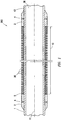
- FIG. 1 illustrates one example, which does not form part of the invention, of grooved swellable packer 200 for positioning downhole in a well to seal with either the interior surface of a borehole or an interior surface of a downhole tubular.
- central axis 11 of grooved swellable packer 200 may be generally aligned with the central bore of the borehole or the central bore of the tubular in the well when grooved swellable packer 200 may be lowered to the desired depth in the well.
- Central axis 11 may also be generally aligned with the central bore of the borehole when grooved swellable packer 200 performs its sealing function.
- grooved swellable packer 200 may include mandrel 1 having a longitudinal axis aligned with central axis 11. Exterior surface 13 of mandrel 1 may be generally cylindrical. Mandrel 1 may be generally tubular, so that fluid may pass through bore 30 of packer 200. Swellable elastomeric body 10 may be positioned over the exterior surface of mandrel 1. In certain examples of the present disclosure, swellable elastomeric body 10 may be fixed to the outer diameter of mandrel 1 and formed by wrapped layers. In other examples, swellable elastomeric body 10 may be molded directly onto the outer diameter of mandrel 1. In other examples of the present disclosure, such as that depicted in FIG.
- swellable elastomeric body 10 may be slipped over mandrel 1 and held in place at either end by endcap 2.
- Endcaps 2 may be held against mandrel 1 by any acceptable method, including, for example, adhesive, mechanical bonding, or as shown in FIG. 1 a set screw 4.
- O-ring 5 may be inserted between endcaps 2 and swellable elastomeric body 10.
- swellable elastomeric body 10 may be held in place with the use of a rigid end ring.
- grooved swellable packer 200 further includes a plurality of grooves 20.
- Grooves 20 are formed in the outer surface of swellable elastomeric body 10.
- grooves 20 are arranged longitudinally along central axis 11.
- grooves 20 may be equally spaced radially or the space between adjacent grooves may vary.
- grooves 20 towards the middle of swellable elastomeric body 10 may have a closer spacing (s1) than the spacing (s2) of grooves 20 toward the extremities of swellable elastomeric body 10 to, for example, further speed seal formation.
- grooves 20 may be formed in the outer surface of swellable elastomeric body 10 by any suitable process including, without limitation, injection molding, material removal (e.g. turning on a lathe, milling, melting, etc.), laminating, wrapping, compressing or other methods recognizable by those of ordinary skill in the art with the benefit of this disclosure.
- grooved packer body 20 may be made up of two or more portions of swellable elastomer.
- grooves may be of varying cross-sectional geometry.
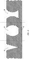
- FIG. 2 shows a series of grooves 21 having rectangular cross sections. Each groove 21 has a depth d and a groove width w g . Grooves may be spaced apart by spacing width w s .
- grooves 20 may have non-rectangular cross-sections.
- grooves 20 may be triangular 22, have concave walls 23, or have convex walls 24.
- specifications such as the number of grooves, depth d, groove width w g , spacing width w s , and cross-sectional shape may be varied to, for example, change the behavior of grooved swellable packer 200 depending on certain design parameters, including but not limited to material properties of swellable elastomeric body 10; length, diameter, and thickness of swellable elastomeric body 10; the rate at which grooved swellable packer 200 may be designed to seal; and the method used to form grooves 20.
- groove width w g may directly impact the efficacy of the grooved swellable packer 200 in making a seal. Too wide of a groove width w g may result in inadequate sealing towards the middle of the groove. Rather than forming a relatively continuous seal between mandrel 1 and the wellbore or surrounding tubular, the base of the groove 20 may not fully contact the wellbore or surrounding tubular when fully swelled. Alternatively, too narrow of a groove width w g may not appreciably aid in sealing over a comparable swellable packer having no grooves. In some embodiments, the ratio between groove width w g and spacing width w s along with the number of grooves 20 may be selected in light of these considerations.
- the number of grooves 20 may be from 5 - 500, from 25 - 100, or from 40 - 75.
- Spacing widths w s between grooves 20 may be between 1.27 cm and 10.16 cm (0.5 and 4 inches), alternatively between 1.9 cm and 5 cm (0.75 and 2 inches), or alternatively about 2.5 cm (1 inch).
- the widths w g of grooves 20 may be between 0.127 cm to 2.54 cm (0.05 inch to 1 inch), alternatively between 0.254 cm to 1.524 cm (0.1 to 0.6 inches), or alternatively between about 0.38 cm to about 0.635 cm (0.15 to about 0.25 inches).
- Depths d of grooves 20 may depend in part on the thickness of swellable elastomeric body 10. As will be appreciated by those of ordinary skill in the art with the benefit of this disclosure, the rate at which grooved swellable packer 200 seals will depend in part on the depth d of grooves 20, but will also appreciate that the depth d of grooves 20 will also affect the integrity of swellable elastomeric body 10. In some embodiments, grooves 20 will not be so deep as to reach mandrel 1.
- the groove penetrates between 1 and 95% of the thickness of swellable elastomeric body 10, between 1 and 50% of the thickness of swellable elastomeric body 10, or between 5 and 30% of the thickness of swellable elastomeric body 10.
- the distance between an endcap 2 and the first groove of grooves 20 may range from 2.5 cm (1 inch) to 30 cm (1 foot), from 7.6 cm (3 inches) to 23 cm (9 inches) or between 10 cm and 18 cm (4 and 7 inches).
- the outer diameter of grooved swellable packer 200 may be less than the surrounding wellbore or tubular member, allowing it to be positioned downhole.
- Swellable elastomeric body 10 may be formed from an elastomeric material which swells in response to the absorption of a swelling fluid, generally an oil or water-based fluid.
- the composition of the swelling fluid needed to activate grooved swellable packer 200 may be selected with consideration of the intended use of the packer. For example, a packer designed to pack off an area of a well at once may be either oil or water-based and activated by a fluid pumped downhole.
- a delayed-use packer may be positioned in a well for long periods of time during, for example, hydrocarbon production.
- a swellable elastomeric body 10 which swells in response to an oil-based fluid would prematurely pack off the annulus.
- a swellable elastomeric body 10 which swells in response to water would therefore be used.
- this selection can allow grooved swellable packer 200 to automatically activate in response to environmental phenomena.
- Such a packer could be used, for example, to provide automatic zonal isolation in response to production of water in an actively producing well.
- grooved swellable packer 200 When grooved swellable packer 200 is activated, the selected swelling fluid comes into contact with swellable elastomeric body 10 and is absorbed by the elastomeric material. In response to the absorption of swelling fluid, swellable elastomeric body 10 increases in volume and eventually contacts the wellbore, or the inner bore of the surrounding tubular. Grooves 20 allow fluid to permeate further into swellable elastomeric body 10 than a comparable swellable body having no grooves. Deeper permeation of swelling fluid may allow swellable elastomeric body 10 to swell more quickly than a comparable swellable body having no grooves. Grooves 20 may also allow unabsorbed fluid to infiltrate or collect in locations around swellable elastomeric body 10 which would be otherwise inaccessible once swellable elastomeric body 10 begins to contact the wellbore or surrounding tubular.
- swellable elastomeric body 10 may form a fluid seal between mandrel 1 and the wellbore or surrounding tubular. Grooves 20 may allow a fluid seal to be established more rapidly and reliably. Pressure may be applied from one or more ends of packer 200.
Landscapes
- Life Sciences & Earth Sciences (AREA)
- Engineering & Computer Science (AREA)
- Geology (AREA)
- Mining & Mineral Resources (AREA)
- Physics & Mathematics (AREA)
- Environmental & Geological Engineering (AREA)
- Fluid Mechanics (AREA)
- General Life Sciences & Earth Sciences (AREA)
- Geochemistry & Mineralogy (AREA)
- Gasket Seals (AREA)
- Consolidation Of Soil By Introduction Of Solidifying Substances Into Soil (AREA)
Description
- This application is a non-provisional application which claims priority from
U.S. provisional application number 61/857,086, filed July 22, 2013 - The present disclosure relates to downhole packers for forming a well seal in an annulus between an inner tubular and either an outer tubular or a borehole wall, or forming a plug with the outer tubular or borehole wall.
- Swellable packers are isolation devices used in a downhole wellbore to seal the inside of the wellbore or a downhole tubular that rely on elastomers to expand and form an annular seal when immersed in certain wellbore fluids. Typically, elastomers used in swellable packers are either oil- or water-sensitive. Various types of swellable packers have been devised, including packers that are fixed to the OD of a tubular and the elastomer formed by wrapped layers, and designs wherein the swellable packer is slipped over the tubular and locked in place.
-
US 3385367 discloses a swellable packer body having circumferential grooves on its outer surface. -
US 2007/0158060 A1 discloses a swellable packer body having circumferential grooves on its outer surface and a single longitudinal groove on its inner surface, wherein the single groove serves as a conduit for control lines. -
US 2012/0168160 A1 ,US 8225861 B2 andUS 2009/0283254 A1 disclose swellable packer bodies with a plurality of longitudinal grooves on their outer surfaces, wherein the grooves serve as conduits for lines or cables. - The invention is defined by the appended claims.
- The present disclosure is best understood from the following detailed description when read with the accompanying figures. It is emphasized that, in accordance with the standard practice in the industry, various features are not drawn to scale. In fact, the dimensions of the various features may be arbitrarily increased or reduced for clarity of discussion.
-
FIG. 1 is a sectional side view of a grooved swellable packer that is consistent with at least one example of the present disclosure. -
FIG. 2 is a partial cross-section of a swellable elastomeric body that is consistent with at least one example of the present disclosure. -
FIG. 3 is a partial cross-section of a swellable elastomeric body exhibiting grooves that are each consistent with at least one example of the present disclosure. -
FIG. 4 is a cross section of a grooved swellable packer that is consistent with at least one example of the present disclosure. - It is to be understood that the following disclosure provides many different embodiments, or examples, for implementing different features of various embodiments. Specific examples of components and arrangements are described below to simplify the present disclosure. These are, of course, merely examples and are not intended to be limiting. In addition, the present disclosure may repeat reference numerals and/or letters in the various examples. This repetition is for the purpose of simplicity and clarity and does not in itself dictate a relationship between the various embodiments and/or configurations discussed.
-
FIG. 1 illustrates one example, which does not form part of the invention, of groovedswellable packer 200 for positioning downhole in a well to seal with either the interior surface of a borehole or an interior surface of a downhole tubular. During operation,central axis 11 of groovedswellable packer 200 may be generally aligned with the central bore of the borehole or the central bore of the tubular in the well when groovedswellable packer 200 may be lowered to the desired depth in the well.Central axis 11 may also be generally aligned with the central bore of the borehole when groovedswellable packer 200 performs its sealing function. - In the example depicted in
FIG. 1 , groovedswellable packer 200 may includemandrel 1 having a longitudinal axis aligned withcentral axis 11.Exterior surface 13 ofmandrel 1 may be generally cylindrical.Mandrel 1 may be generally tubular, so that fluid may pass throughbore 30 ofpacker 200. Swellableelastomeric body 10 may be positioned over the exterior surface ofmandrel 1. In certain examples of the present disclosure, swellableelastomeric body 10 may be fixed to the outer diameter ofmandrel 1 and formed by wrapped layers. In other examples, swellableelastomeric body 10 may be molded directly onto the outer diameter ofmandrel 1. In other examples of the present disclosure, such as that depicted inFIG. 1 , swellableelastomeric body 10 may be slipped overmandrel 1 and held in place at either end byendcap 2.Endcaps 2 may be held againstmandrel 1 by any acceptable method, including, for example, adhesive, mechanical bonding, or as shown inFIG. 1 aset screw 4. In certain embodiments of the present disclosure, O-ring 5 may be inserted betweenendcaps 2 and swellableelastomeric body 10. In other embodiments of the present disclosure swellableelastomeric body 10 may be held in place with the use of a rigid end ring. - According to the invention, grooved
swellable packer 200 further includes a plurality ofgrooves 20.Grooves 20 are formed in the outer surface of swellableelastomeric body 10. According to the invention,grooves 20 are arranged longitudinally alongcentral axis 11. In some embodiments,grooves 20 may be equally spaced radially or the space between adjacent grooves may vary. For example and not forming part of the invention, as depicted inFIG. 4 ,grooves 20 towards the middle of swellableelastomeric body 10 may have a closer spacing (s1) than the spacing (s2) ofgrooves 20 toward the extremities of swellableelastomeric body 10 to, for example, further speed seal formation. One having ordinary skill in the art with the benefit of this disclosure will understand thatgrooves 20 may be formed in the outer surface of swellableelastomeric body 10 by any suitable process including, without limitation, injection molding, material removal (e.g. turning on a lathe, milling, melting, etc.), laminating, wrapping, compressing or other methods recognizable by those of ordinary skill in the art with the benefit of this disclosure. In some embodiments,grooved packer body 20 may be made up of two or more portions of swellable elastomer. - Additionally, in some embodiments, grooves may be of varying cross-sectional geometry. For example,
FIG. 2 shows a series ofgrooves 21 having rectangular cross sections. Eachgroove 21 has a depth d and a groove width wg. Grooves may be spaced apart by spacing width ws. Furthermore, as shown byFIG. 3 ,grooves 20 may have non-rectangular cross-sections. For example, in some embodiments,grooves 20 may be triangular 22, haveconcave walls 23, or haveconvex walls 24. One of ordinary skill in the art with the benefit of this disclosure will understand that specifications such as the number of grooves, depth d, groove width wg, spacing width ws, and cross-sectional shape may be varied to, for example, change the behavior of groovedswellable packer 200 depending on certain design parameters, including but not limited to material properties of swellableelastomeric body 10; length, diameter, and thickness of swellableelastomeric body 10; the rate at which groovedswellable packer 200 may be designed to seal; and the method used to formgrooves 20. One of ordinary skill in the art will also understand that one or more of these specifications may be varied within the same swellableelastomeric body 10 such that grooves 20 in one section of swellableelastomeric body 10 may be different from those in a different section of swellableelastomeric body 10. - For example, the selection of groove width wg may directly impact the efficacy of the grooved
swellable packer 200 in making a seal. Too wide of a groove width wg may result in inadequate sealing towards the middle of the groove. Rather than forming a relatively continuous seal betweenmandrel 1 and the wellbore or surrounding tubular, the base of thegroove 20 may not fully contact the wellbore or surrounding tubular when fully swelled. Alternatively, too narrow of a groove width wg may not appreciably aid in sealing over a comparable swellable packer having no grooves. In some embodiments, the ratio between groove width wg and spacing width ws along with the number ofgrooves 20 may be selected in light of these considerations. - In some embodiments, the number of
grooves 20 may be from 5 - 500, from 25 - 100, or from 40 - 75. In some embodiments, Spacing widths ws betweengrooves 20 may be between 1.27 cm and 10.16 cm (0.5 and 4 inches), alternatively between 1.9 cm and 5 cm (0.75 and 2 inches), or alternatively about 2.5 cm (1 inch). In some embodiments, the widths wg ofgrooves 20 may be between 0.127 cm to 2.54 cm (0.05 inch to 1 inch), alternatively between 0.254 cm to 1.524 cm (0.1 to 0.6 inches), or alternatively between about 0.38 cm to about 0.635 cm (0.15 to about 0.25 inches). - In some embodiments, Depths d of
grooves 20 may depend in part on the thickness of swellableelastomeric body 10. As will be appreciated by those of ordinary skill in the art with the benefit of this disclosure, the rate at which groovedswellable packer 200 seals will depend in part on the depth d ofgrooves 20, but will also appreciate that the depth d ofgrooves 20 will also affect the integrity of swellableelastomeric body 10. In some embodiments,grooves 20 will not be so deep as to reachmandrel 1. In certain embodiments of the present disclosure, the groove penetrates between 1 and 95% of the thickness of swellableelastomeric body 10, between 1 and 50% of the thickness of swellableelastomeric body 10, or between 5 and 30% of the thickness of swellableelastomeric body 10. - In some examples, the distance between an
endcap 2 and the first groove ofgrooves 20 may range from 2.5 cm (1 inch) to 30 cm (1 foot), from 7.6 cm (3 inches) to 23 cm (9 inches) or between 10 cm and 18 cm (4 and 7 inches). - In some embodiments, referring to
FIG. 1 , as groovedswellable packer 200 is inserted into the well, the outer diameter of groovedswellable packer 200 may be less than the surrounding wellbore or tubular member, allowing it to be positioned downhole. Swellableelastomeric body 10 may be formed from an elastomeric material which swells in response to the absorption of a swelling fluid, generally an oil or water-based fluid. The composition of the swelling fluid needed to activate groovedswellable packer 200 may be selected with consideration of the intended use of the packer. For example, a packer designed to pack off an area of a well at once may be either oil or water-based and activated by a fluid pumped downhole. Alternatively, a delayed-use packer may be positioned in a well for long periods of time during, for example, hydrocarbon production. A swellableelastomeric body 10 which swells in response to an oil-based fluid would prematurely pack off the annulus. A swellableelastomeric body 10 which swells in response to water would therefore be used. Furthermore, one having ordinary skill in the art would understand that this selection can allow groovedswellable packer 200 to automatically activate in response to environmental phenomena. Such a packer could be used, for example, to provide automatic zonal isolation in response to production of water in an actively producing well. - When grooved
swellable packer 200 is activated, the selected swelling fluid comes into contact with swellableelastomeric body 10 and is absorbed by the elastomeric material. In response to the absorption of swelling fluid, swellableelastomeric body 10 increases in volume and eventually contacts the wellbore, or the inner bore of the surrounding tubular.Grooves 20 allow fluid to permeate further into swellableelastomeric body 10 than a comparable swellable body having no grooves. Deeper permeation of swelling fluid may allow swellableelastomeric body 10 to swell more quickly than a comparable swellable body having no grooves.Grooves 20 may also allow unabsorbed fluid to infiltrate or collect in locations around swellableelastomeric body 10 which would be otherwise inaccessible once swellableelastomeric body 10 begins to contact the wellbore or surrounding tubular. - Continued swelling of swellable
elastomeric body 10 may form a fluid seal betweenmandrel 1 and the wellbore or surrounding tubular.Grooves 20 may allow a fluid seal to be established more rapidly and reliably. Pressure may be applied from one or more ends ofpacker 200.
Claims (14)
- A swellable packer (200) comprising:a generally tubular mandrel (1) having a central axis (11) and an exterior cylindrical surface (13); anda swellable elastomeric body (10) coupled to the exterior cylindrical surface (13) of the mandrel (1), the swellable elastomeric body (10) comprising a plurality of grooves (20) formed in the outer surface of the swellable elastomeric body (10), the swellable elastomeric body (10) having a circumference and a thickness, wherein the grooves (20) are arranged longitudinally along the swellable elastomeric body (10) and parallel to the central axis (11), the swellable packer (200) characterised in that the grooves (20) are adapted to allow a swelling fluid to permeate further into the swellable elastomeric body (10) than if the swellable elastomeric body (10) had no grooves.
- The swellable packer (200) of claim 1, wherein the distance between each groove of the plurality of grooves (20) is between 1.27 cm and 10.16 cm (0.5 and 4 inches).
- The swellable packer (200) of claim 1, wherein the width of each groove of the plurality of grooves (20) is between 0.127 cm and 2.54 cm (0.05 inches and 1 inch).
- The swellable packer (200) of claim 1, wherein the depth of each groove of the plurality of grooves (200) is between 1% and 50% of the thickness of the swellable elastomeric body (10).
- The swellable packer (200) of claim 1, wherein the swellable elastomeric body (10) is formed by wrapped layers.
- The swellable packer (200) of claim 1, wherein the swellable elastomeric body (10) is slipped over the mandrel (1) and held in place by the ends of the swellable elastomeric body (10); optionally, wherein the ends are held against the mandrel (1).
- The swellable packer (200) of claim 1, wherein at least one groove of the plurality of grooves (200): has a rectangular cross-section; or, has a triangular cross-section; or,
further comprises side-walls having a curved profile. - The swellable packer (200) of claim 1, wherein the swellable elastomeric body (10) swells in response to contact with a swelling fluid, the swelling fluid selected from a group consisting of water based and oil based fluids.
- A method of isolating a section of wellbore comprising:providing a swellable packer (200), wherein the swellable packer (200) comprises:a generally tubular mandrel (1) having a central axis (11) and an exterior cylindrical surface (13); anda swellable elastomeric body (10) fixed to the exterior cylindrical surface (13) of the mandrel (1), wherein the swellable elastomeric body (10) comprises a plurality of grooves (20) formed in the outer surface of the swellable elastomeric body (10), the grooves (20) adapted to allow a swelling fluid to permeate further into the swellable elastomeric body than if the swellable elastomeric body (10) had no grooves, the grooves arranged longitudinally along the swellable elastomeric body (10) and parallel to the central axis (11) and wherein the generally tubular elastomeric sleeve has a circumference and a thickness;inserting the swellable packer (200) into the section of wellbore;exposing the swellable packer (200) to a swelling fluid; andsealing the section of wellbore.
- The method of claim 9, wherein the swelling fluid is water based; or, wherein the swelling fluid is oil based.
- The method of claim 9 further comprising:
flowing the swelling fluid into the plurality of grooves (20). - The method of claim 9, wherein the exposing of the swellable packer (200) to a swelling fluid occurs in response to environmental conditions.
- A method of forming a swellable packer (200) comprising:providing a generally tubular mandrel (1) having a central axis (11) and an exterior cylindrical surface (13);providing a swellable elastomeric body (10) having a circumference and a thickness;coupling the swellable elastomeric body (10) to the exterior cylindrical surface (13) of the mandrel (1); andforming a plurality of grooves in the outer surface of the swellable elastomeric body, the grooves arranged longitudinally along the swellable elastomeric body and parallel to the central axis, the grooves adapted to allow a swelling fluid to permeate further into the swellable elastomeric body than if the swellable elastomeric body (10) had no grooves.
- The method of claim 13, wherein:the forming operation comprises:turning the swellable elastomeric body (10) on a lathe, andremoving material to form one of the grooves in the swellable elastomeric body (10); or,the coupling and forming operations comprise:molding the swellable elastomeric body (10) to the exterior cylindrical surface (13) of the mandrel (1); andmolding one of the grooves in the swellable elastomeric body (10); or,the coupling and forming operations comprise:wrapping layers of the swellable elastomeric body (10) onto the mandrel (1); andwrapping fewer layers of the swellable elastomeric body (10) in a first location along the mandrel (1) than at locations adjacent to the first location, thereby forming one of the grooves; or,the forming operation comprises:
selectively compressing the swellable elastomeric body (10) in at least one location, causing one of the grooves to be formed.
Applications Claiming Priority (2)
| Application Number | Priority Date | Filing Date | Title |
|---|---|---|---|
| US201361857086P | 2013-07-22 | 2013-07-22 | |
| PCT/US2014/047623 WO2015013276A1 (en) | 2013-07-22 | 2014-07-22 | Grooved swellable packer |
Publications (3)
| Publication Number | Publication Date |
|---|---|
| EP3025013A1 EP3025013A1 (en) | 2016-06-01 |
| EP3025013A4 EP3025013A4 (en) | 2017-03-22 |
| EP3025013B1 true EP3025013B1 (en) | 2019-11-06 |
Family
ID=52342646
Family Applications (1)
| Application Number | Title | Priority Date | Filing Date |
|---|---|---|---|
| EP14829833.4A Active EP3025013B1 (en) | 2013-07-22 | 2014-07-22 | Grooved swellable packer |
Country Status (5)
| Country | Link |
|---|---|
| US (1) | US9976380B2 (en) |
| EP (1) | EP3025013B1 (en) |
| AU (1) | AU2014293305A1 (en) |
| CA (1) | CA2919009C (en) |
| WO (1) | WO2015013276A1 (en) |
Families Citing this family (34)
| Publication number | Priority date | Publication date | Assignee | Title |
|---|---|---|---|---|
| WO2015013278A1 (en) | 2013-07-22 | 2015-01-29 | Tam International, Inc. | Swellable casing anchor |
| AU2014293305A1 (en) * | 2013-07-22 | 2016-02-11 | Tam International, Inc. | Grooved swellable packer |
| NL2013568B1 (en) * | 2014-10-03 | 2016-10-03 | Ruma Products Holding B V | Seal and assembly comprising the seal and method for applying the seal. |
| US20180087344A1 (en) * | 2016-09-29 | 2018-03-29 | Cnpc Usa Corporation | Multi-sectional swellable packer |
| MY209755A (en) * | 2019-02-11 | 2025-07-31 | Halliburton Energy Services Inc | Energizing seals with swellable materials |
| NO20210729A1 (en) | 2019-02-22 | 2021-06-04 | Halliburton Energy Services Inc | An Expanding Metal Sealant For Use With Multilateral Completion Systems |
| GB2599552B (en) | 2019-07-31 | 2023-04-26 | Halliburton Energy Services Inc | Methods to monitor a metallic sealant deployed in a wellbore, methods to monitor fluid displacement, and downhole metallic sealant measurement systems |
| MX2022000101A (en) | 2019-08-06 | 2022-02-03 | Halliburton Energy Services Inc | Expandable metal gas lift mandrel plug. |
| US10961804B1 (en) | 2019-10-16 | 2021-03-30 | Halliburton Energy Services, Inc. | Washout prevention element for expandable metal sealing elements |
| US11519239B2 (en) | 2019-10-29 | 2022-12-06 | Halliburton Energy Services, Inc. | Running lines through expandable metal sealing elements |
| US12480373B2 (en) | 2019-11-13 | 2025-11-25 | Halliburton Energy Services, Inc. | Actuating a downhole device with a reactive metal |
| US11761290B2 (en) | 2019-12-18 | 2023-09-19 | Halliburton Energy Services, Inc. | Reactive metal sealing elements for a liner hanger |
| US11499399B2 (en) | 2019-12-18 | 2022-11-15 | Halliburton Energy Services, Inc. | Pressure reducing metal elements for liner hangers |
| AU2021209133B2 (en) | 2020-01-17 | 2025-08-28 | Halliburton Energy Services, Inc. | Voltage to accelerate/decelerate expandable metal |
| MY210348A (en) | 2020-01-17 | 2025-09-12 | Halliburton Energy Services Inc | Heaters to accelerate setting of expandable metal |
| GB2606899B (en) | 2020-02-28 | 2024-01-17 | Halliburton Energy Services Inc | Textured surfaces of expanding metal for centralizer, mixing, and differential sticking |
| WO2022035700A1 (en) | 2020-08-13 | 2022-02-17 | Halliburton Energy Services, Inc. | Expandable metal displacement plug |
| US11761293B2 (en) | 2020-12-14 | 2023-09-19 | Halliburton Energy Services, Inc. | Swellable packer assemblies, downhole packer systems, and methods to seal a wellbore |
| US11572749B2 (en) | 2020-12-16 | 2023-02-07 | Halliburton Energy Services, Inc. | Non-expanding liner hanger |
| GB2618745B (en) | 2021-04-12 | 2025-07-09 | Halliburton Energy Services Inc | Expandable metal as backup for elastomeric elements |
| US11578498B2 (en) | 2021-04-12 | 2023-02-14 | Halliburton Energy Services, Inc. | Expandable metal for anchoring posts |
| US11879304B2 (en) | 2021-05-17 | 2024-01-23 | Halliburton Energy Services, Inc. | Reactive metal for cement assurance |
| AU2021445878A1 (en) | 2021-05-21 | 2023-08-10 | Halliburton Energy Services, Inc. | A wellbore anchor including one or more activation chambers |
| CA3213939A1 (en) | 2021-05-28 | 2022-12-01 | Stephen Michael Greci | Individual separate chunks of expandable metal |
| RO138042A2 (en) | 2021-05-28 | 2024-03-29 | Halliburton Energy Services, Inc. | Rapid setting expandable metal |
| MX2023012186A (en) | 2021-05-29 | 2023-10-25 | Halliburton Energy Services Inc | Using expandable metal as an alternate to existing metal to metal seals. |
| WO2022255988A1 (en) | 2021-06-01 | 2022-12-08 | Halliburton Energy Services, Inc. | Expanding metal used in forming support structures |
| WO2023059312A1 (en) | 2021-10-05 | 2023-04-13 | Halliburton Energy Services, Inc. | Expandable metal sealing/anchoring tool |
| US12305459B2 (en) | 2022-06-15 | 2025-05-20 | Halliburton Energy Services, Inc. | Sealing/anchoring tool employing an expandable metal circlet |
| US12234701B2 (en) | 2022-09-12 | 2025-02-25 | Saudi Arabian Oil Company | Tubing hangers and related methods of isolating a tubing |
| US12385340B2 (en) | 2022-12-05 | 2025-08-12 | Halliburton Energy Services, Inc. | Reduced backlash sealing/anchoring assembly |
| US12188328B2 (en) | 2023-05-15 | 2025-01-07 | Saudi Arabian Oil Company | Wellbore back pressure valve with pressure gauge |
| US12442257B2 (en) | 2023-05-23 | 2025-10-14 | Saudi Arabian Oil Company | Completing and working over a wellbore |
| US12612843B2 (en) | 2023-12-26 | 2026-04-28 | Halliburton Energy Services, Inc. | Mechanical support for expandable liner hanger |
Citations (2)
| Publication number | Priority date | Publication date | Assignee | Title |
|---|---|---|---|---|
| US20090283254A1 (en) * | 2008-05-14 | 2009-11-19 | Halliburton Energy Services, Inc. | Swellable Packer With Variable Quantity Feed-Throughs for Lines |
| US8225861B2 (en) * | 2009-03-11 | 2012-07-24 | Baker Hughes Incorporated | Sealing feed through lines for downhole swelling packers |
Family Cites Families (32)
| Publication number | Priority date | Publication date | Assignee | Title |
|---|---|---|---|---|
| US2420226A (en) | 1944-11-03 | 1947-05-06 | Gates Rubber Co | Oil well packer |
| US3385367A (en) | 1966-12-07 | 1968-05-28 | Kollsman Paul | Sealing device for perforated well casing |
| US4871179A (en) | 1983-01-24 | 1989-10-03 | Completion Tool Company | Inflatable packer with roughened mandrel |
| EA009320B1 (en) * | 2004-03-11 | 2007-12-28 | Шелл Интернэшнл Рисерч Маатсхаппий Б.В. | System for sealing an annular space in a wellbore |
| US7721799B2 (en) * | 2006-10-06 | 2010-05-25 | Baski, Inc. | Flow control packer (FCP) and aquifer storage and recovery (ASR) system |
| EP2086762A2 (en) | 2006-10-20 | 2009-08-12 | Halliburton Energy Services, Inc. | Swellable packer construction for continuous or segmented tubing |
| GB2446399B (en) * | 2007-02-07 | 2009-07-15 | Swelltec Ltd | Downhole apparatus and method |
| US20090139708A1 (en) | 2007-06-06 | 2009-06-04 | Baker Hughes Incorporated | Wrap-On Reactive Element Barrier Packer and Method of Creating Same |
| GB2464428B (en) | 2007-08-20 | 2012-01-25 | Shell Int Research | Method of creating an annular seal around a tubular element |
| NO334336B1 (en) * | 2007-10-29 | 2014-02-10 | Tdw Offshore Services As | Assembly for use with a plug |
| US8555961B2 (en) * | 2008-01-07 | 2013-10-15 | Halliburton Energy Services, Inc. | Swellable packer with composite material end rings |
| US7931092B2 (en) | 2008-02-13 | 2011-04-26 | Stowe Woodward, L.L.C. | Packer element with recesses for downwell packing system and method of its use |
| FR2927936B1 (en) * | 2008-02-21 | 2010-03-26 | Vam Drilling France | DRILL LINING ELEMENT, DRILLING ROD AND CORRESPONDING DRILL ROD TRAIN |
| GB2457894B (en) * | 2008-02-27 | 2011-12-14 | Swelltec Ltd | Downhole apparatus and method |
| GB0804029D0 (en) * | 2008-03-04 | 2008-04-09 | Swelltec Ltd | Downhole apparatus and method |
| GB2465206B (en) | 2008-11-11 | 2011-11-23 | Swelltec Ltd | Swellable apparatus and method |
| US8087459B2 (en) | 2009-03-31 | 2012-01-03 | Weatherford/Lamb, Inc. | Packer providing multiple seals and having swellable element isolatable from the wellbore |
| US8763687B2 (en) * | 2009-05-01 | 2014-07-01 | Weatherford/Lamb, Inc. | Wellbore isolation tool using sealing element having shape memory polymer |
| WO2011150367A1 (en) * | 2010-05-27 | 2011-12-01 | Longwood Elastomers, Inc. | Improved process for manufacturing swellable downhole packers and associated products |
| US8960312B2 (en) | 2010-06-30 | 2015-02-24 | Halliburton Energy Services, Inc. | Mitigating leaks in production tubulars |
| US8397803B2 (en) | 2010-07-06 | 2013-03-19 | Halliburton Energy Services, Inc. | Packing element system with profiled surface |
| US20120012343A1 (en) | 2010-07-13 | 2012-01-19 | Wilkin James F | Downhole Packer Having Swellable Sleeve |
| US8997854B2 (en) | 2010-07-23 | 2015-04-07 | Weatherford Technology Holdings, Llc | Swellable packer anchors |
| US8453728B2 (en) | 2010-07-27 | 2013-06-04 | Halliburton Energy Services, Inc. | Apparatus and method for depth referencing downhole tubular strings |
| US8800670B2 (en) | 2010-08-09 | 2014-08-12 | Weatherford/Lamb, Inc. | Filler rings for swellable packers and method for using same |
| GB2497124C (en) * | 2011-12-01 | 2020-07-01 | Xtreme Well Tech Limited | Apparatus for use in a fluid conduit |
| US9617821B2 (en) * | 2012-06-20 | 2017-04-11 | Halliburton Energy Services, Inc. | Swellable packer with enhanced operating envelope |
| US9476281B2 (en) * | 2013-06-20 | 2016-10-25 | Halliburton Energy Services, Inc. | High pressure swell seal |
| WO2015013278A1 (en) * | 2013-07-22 | 2015-01-29 | Tam International, Inc. | Swellable casing anchor |
| AU2014293305A1 (en) * | 2013-07-22 | 2016-02-11 | Tam International, Inc. | Grooved swellable packer |
| US20160010422A1 (en) * | 2014-07-09 | 2016-01-14 | Weatherford Technology Holdings Llc | Compressible Packing Element for Continuous Feed-Through Line |
| MX2017000567A (en) * | 2014-07-28 | 2017-05-01 | Baker Hughes Inc | PERFORATION FUND SYSTEM THAT USES A SHUTTER AND METHOD SETTLEMENT BOARD. |
-
2014
- 2014-07-22 AU AU2014293305A patent/AU2014293305A1/en not_active Abandoned
- 2014-07-22 CA CA2919009A patent/CA2919009C/en active Active
- 2014-07-22 EP EP14829833.4A patent/EP3025013B1/en active Active
- 2014-07-22 WO PCT/US2014/047623 patent/WO2015013276A1/en not_active Ceased
- 2014-07-22 US US14/337,871 patent/US9976380B2/en active Active
Patent Citations (2)
| Publication number | Priority date | Publication date | Assignee | Title |
|---|---|---|---|---|
| US20090283254A1 (en) * | 2008-05-14 | 2009-11-19 | Halliburton Energy Services, Inc. | Swellable Packer With Variable Quantity Feed-Throughs for Lines |
| US8225861B2 (en) * | 2009-03-11 | 2012-07-24 | Baker Hughes Incorporated | Sealing feed through lines for downhole swelling packers |
Also Published As
| Publication number | Publication date |
|---|---|
| EP3025013A1 (en) | 2016-06-01 |
| WO2015013276A1 (en) | 2015-01-29 |
| EP3025013A4 (en) | 2017-03-22 |
| US9976380B2 (en) | 2018-05-22 |
| CA2919009C (en) | 2019-11-26 |
| CA2919009A1 (en) | 2015-01-29 |
| US20150021044A1 (en) | 2015-01-22 |
| AU2014293305A1 (en) | 2016-02-11 |
Similar Documents
| Publication | Publication Date | Title |
|---|---|---|
| US9976380B2 (en) | Grooved swellable packer | |
| US10364636B2 (en) | Swellable casing anchor | |
| EP2096256B1 (en) | Method of forming a downhole apparatus | |
| AU2015270490B2 (en) | Downhole expandable metal tubular | |
| EP2586963A1 (en) | Sealing material for annular barriers | |
| RU2477366C1 (en) | Downhole tool, device for installation in downhole tool, and downhole tool assembly method | |
| CA2988361A1 (en) | Downhole expandable metal tubular | |
| AU2017232172A1 (en) | A tubular connection | |
| US20160010422A1 (en) | Compressible Packing Element for Continuous Feed-Through Line | |
| AU2017337283B2 (en) | System, method, and sleeve, for cladding an underground wellbore passage | |
| US9739112B2 (en) | Downhole packer | |
| US11208866B2 (en) | Annular barrier | |
| CN113891981A (en) | Annular barrier with snap connection | |
| AU2018202425B2 (en) | Method of forming a downhole apparatus | |
| US10731435B2 (en) | Annular barrier for small diameter wells | |
| CA2937893A1 (en) | Pressure releaving means | |
| AU2010214650A1 (en) | Method of forming a downhole apparatus |
Legal Events
| Date | Code | Title | Description |
|---|---|---|---|
| PUAI | Public reference made under article 153(3) epc to a published international application that has entered the european phase |
Free format text: ORIGINAL CODE: 0009012 |
|
| 17P | Request for examination filed |
Effective date: 20160122 |
|
| AK | Designated contracting states |
Kind code of ref document: A1 Designated state(s): AL AT BE BG CH CY CZ DE DK EE ES FI FR GB GR HR HU IE IS IT LI LT LU LV MC MK MT NL NO PL PT RO RS SE SI SK SM TR |
|
| AX | Request for extension of the european patent |
Extension state: BA ME |
|
| DAX | Request for extension of the european patent (deleted) | ||
| REG | Reference to a national code |
Ref country code: DE Ref legal event code: R079 Ref document number: 602014056446 Country of ref document: DE Free format text: PREVIOUS MAIN CLASS: E21B0033127000 Ipc: E21B0033120000 |
|
| A4 | Supplementary search report drawn up and despatched |
Effective date: 20170216 |
|
| RIC1 | Information provided on ipc code assigned before grant |
Ipc: E21B 33/12 20060101AFI20170210BHEP |
|
| STAA | Information on the status of an ep patent application or granted ep patent |
Free format text: STATUS: EXAMINATION IS IN PROGRESS |
|
| 17Q | First examination report despatched |
Effective date: 20180222 |
|
| GRAP | Despatch of communication of intention to grant a patent |
Free format text: ORIGINAL CODE: EPIDOSNIGR1 |
|
| STAA | Information on the status of an ep patent application or granted ep patent |
Free format text: STATUS: GRANT OF PATENT IS INTENDED |
|
| INTG | Intention to grant announced |
Effective date: 20190531 |
|
| GRAS | Grant fee paid |
Free format text: ORIGINAL CODE: EPIDOSNIGR3 |
|
| GRAA | (expected) grant |
Free format text: ORIGINAL CODE: 0009210 |
|
| STAA | Information on the status of an ep patent application or granted ep patent |
Free format text: STATUS: THE PATENT HAS BEEN GRANTED |
|
| AK | Designated contracting states |
Kind code of ref document: B1 Designated state(s): AL AT BE BG CH CY CZ DE DK EE ES FI FR GB GR HR HU IE IS IT LI LT LU LV MC MK MT NL NO PL PT RO RS SE SI SK SM TR |
|
| REG | Reference to a national code |
Ref country code: GB Ref legal event code: FG4D |
|
| REG | Reference to a national code |
Ref country code: CH Ref legal event code: EP Ref country code: AT Ref legal event code: REF Ref document number: 1198955 Country of ref document: AT Kind code of ref document: T Effective date: 20191115 |
|
| REG | Reference to a national code |
Ref country code: IE Ref legal event code: FG4D |
|
| REG | Reference to a national code |
Ref country code: DE Ref legal event code: R096 Ref document number: 602014056446 Country of ref document: DE |
|
| REG | Reference to a national code |
Ref country code: NO Ref legal event code: T2 Effective date: 20191106 |
|
| REG | Reference to a national code |
Ref country code: NL Ref legal event code: MP Effective date: 20191106 |
|
| REG | Reference to a national code |
Ref country code: LT Ref legal event code: MG4D |
|
| PG25 | Lapsed in a contracting state [announced via postgrant information from national office to epo] |
Ref country code: FI Free format text: LAPSE BECAUSE OF FAILURE TO SUBMIT A TRANSLATION OF THE DESCRIPTION OR TO PAY THE FEE WITHIN THE PRESCRIBED TIME-LIMIT Effective date: 20191106 Ref country code: BG Free format text: LAPSE BECAUSE OF FAILURE TO SUBMIT A TRANSLATION OF THE DESCRIPTION OR TO PAY THE FEE WITHIN THE PRESCRIBED TIME-LIMIT Effective date: 20200206 Ref country code: SE Free format text: LAPSE BECAUSE OF FAILURE TO SUBMIT A TRANSLATION OF THE DESCRIPTION OR TO PAY THE FEE WITHIN THE PRESCRIBED TIME-LIMIT Effective date: 20191106 Ref country code: LV Free format text: LAPSE BECAUSE OF FAILURE TO SUBMIT A TRANSLATION OF THE DESCRIPTION OR TO PAY THE FEE WITHIN THE PRESCRIBED TIME-LIMIT Effective date: 20191106 Ref country code: NL Free format text: LAPSE BECAUSE OF FAILURE TO SUBMIT A TRANSLATION OF THE DESCRIPTION OR TO PAY THE FEE WITHIN THE PRESCRIBED TIME-LIMIT Effective date: 20191106 Ref country code: GR Free format text: LAPSE BECAUSE OF FAILURE TO SUBMIT A TRANSLATION OF THE DESCRIPTION OR TO PAY THE FEE WITHIN THE PRESCRIBED TIME-LIMIT Effective date: 20200207 Ref country code: PT Free format text: LAPSE BECAUSE OF FAILURE TO SUBMIT A TRANSLATION OF THE DESCRIPTION OR TO PAY THE FEE WITHIN THE PRESCRIBED TIME-LIMIT Effective date: 20200306 Ref country code: LT Free format text: LAPSE BECAUSE OF FAILURE TO SUBMIT A TRANSLATION OF THE DESCRIPTION OR TO PAY THE FEE WITHIN THE PRESCRIBED TIME-LIMIT Effective date: 20191106 Ref country code: PL Free format text: LAPSE BECAUSE OF FAILURE TO SUBMIT A TRANSLATION OF THE DESCRIPTION OR TO PAY THE FEE WITHIN THE PRESCRIBED TIME-LIMIT Effective date: 20191106 |
|
| PG25 | Lapsed in a contracting state [announced via postgrant information from national office to epo] |
Ref country code: IS Free format text: LAPSE BECAUSE OF FAILURE TO SUBMIT A TRANSLATION OF THE DESCRIPTION OR TO PAY THE FEE WITHIN THE PRESCRIBED TIME-LIMIT Effective date: 20200306 Ref country code: HR Free format text: LAPSE BECAUSE OF FAILURE TO SUBMIT A TRANSLATION OF THE DESCRIPTION OR TO PAY THE FEE WITHIN THE PRESCRIBED TIME-LIMIT Effective date: 20191106 Ref country code: RS Free format text: LAPSE BECAUSE OF FAILURE TO SUBMIT A TRANSLATION OF THE DESCRIPTION OR TO PAY THE FEE WITHIN THE PRESCRIBED TIME-LIMIT Effective date: 20191106 |
|
| PG25 | Lapsed in a contracting state [announced via postgrant information from national office to epo] |
Ref country code: AL Free format text: LAPSE BECAUSE OF FAILURE TO SUBMIT A TRANSLATION OF THE DESCRIPTION OR TO PAY THE FEE WITHIN THE PRESCRIBED TIME-LIMIT Effective date: 20191106 |
|
| PG25 | Lapsed in a contracting state [announced via postgrant information from national office to epo] |
Ref country code: DK Free format text: LAPSE BECAUSE OF FAILURE TO SUBMIT A TRANSLATION OF THE DESCRIPTION OR TO PAY THE FEE WITHIN THE PRESCRIBED TIME-LIMIT Effective date: 20191106 Ref country code: EE Free format text: LAPSE BECAUSE OF FAILURE TO SUBMIT A TRANSLATION OF THE DESCRIPTION OR TO PAY THE FEE WITHIN THE PRESCRIBED TIME-LIMIT Effective date: 20191106 Ref country code: ES Free format text: LAPSE BECAUSE OF FAILURE TO SUBMIT A TRANSLATION OF THE DESCRIPTION OR TO PAY THE FEE WITHIN THE PRESCRIBED TIME-LIMIT Effective date: 20191106 Ref country code: CZ Free format text: LAPSE BECAUSE OF FAILURE TO SUBMIT A TRANSLATION OF THE DESCRIPTION OR TO PAY THE FEE WITHIN THE PRESCRIBED TIME-LIMIT Effective date: 20191106 Ref country code: RO Free format text: LAPSE BECAUSE OF FAILURE TO SUBMIT A TRANSLATION OF THE DESCRIPTION OR TO PAY THE FEE WITHIN THE PRESCRIBED TIME-LIMIT Effective date: 20191106 |
|
| REG | Reference to a national code |
Ref country code: DE Ref legal event code: R097 Ref document number: 602014056446 Country of ref document: DE |
|
| REG | Reference to a national code |
Ref country code: AT Ref legal event code: MK05 Ref document number: 1198955 Country of ref document: AT Kind code of ref document: T Effective date: 20191106 |
|
| PG25 | Lapsed in a contracting state [announced via postgrant information from national office to epo] |
Ref country code: SK Free format text: LAPSE BECAUSE OF FAILURE TO SUBMIT A TRANSLATION OF THE DESCRIPTION OR TO PAY THE FEE WITHIN THE PRESCRIBED TIME-LIMIT Effective date: 20191106 Ref country code: SM Free format text: LAPSE BECAUSE OF FAILURE TO SUBMIT A TRANSLATION OF THE DESCRIPTION OR TO PAY THE FEE WITHIN THE PRESCRIBED TIME-LIMIT Effective date: 20191106 |
|
| PLBE | No opposition filed within time limit |
Free format text: ORIGINAL CODE: 0009261 |
|
| STAA | Information on the status of an ep patent application or granted ep patent |
Free format text: STATUS: NO OPPOSITION FILED WITHIN TIME LIMIT |
|
| 26N | No opposition filed |
Effective date: 20200807 |
|
| PG25 | Lapsed in a contracting state [announced via postgrant information from national office to epo] |
Ref country code: SI Free format text: LAPSE BECAUSE OF FAILURE TO SUBMIT A TRANSLATION OF THE DESCRIPTION OR TO PAY THE FEE WITHIN THE PRESCRIBED TIME-LIMIT Effective date: 20191106 Ref country code: AT Free format text: LAPSE BECAUSE OF FAILURE TO SUBMIT A TRANSLATION OF THE DESCRIPTION OR TO PAY THE FEE WITHIN THE PRESCRIBED TIME-LIMIT Effective date: 20191106 |
|
| PG25 | Lapsed in a contracting state [announced via postgrant information from national office to epo] |
Ref country code: IT Free format text: LAPSE BECAUSE OF FAILURE TO SUBMIT A TRANSLATION OF THE DESCRIPTION OR TO PAY THE FEE WITHIN THE PRESCRIBED TIME-LIMIT Effective date: 20191106 |
|
| REG | Reference to a national code |
Ref country code: DE Ref legal event code: R119 Ref document number: 602014056446 Country of ref document: DE |
|
| PG25 | Lapsed in a contracting state [announced via postgrant information from national office to epo] |
Ref country code: MC Free format text: LAPSE BECAUSE OF FAILURE TO SUBMIT A TRANSLATION OF THE DESCRIPTION OR TO PAY THE FEE WITHIN THE PRESCRIBED TIME-LIMIT Effective date: 20191106 |
|
| REG | Reference to a national code |
Ref country code: CH Ref legal event code: PL |
|
| REG | Reference to a national code |
Ref country code: BE Ref legal event code: MM Effective date: 20200731 |
|
| PG25 | Lapsed in a contracting state [announced via postgrant information from national office to epo] |
Ref country code: LU Free format text: LAPSE BECAUSE OF NON-PAYMENT OF DUE FEES Effective date: 20200722 Ref country code: LI Free format text: LAPSE BECAUSE OF NON-PAYMENT OF DUE FEES Effective date: 20200731 Ref country code: FR Free format text: LAPSE BECAUSE OF NON-PAYMENT OF DUE FEES Effective date: 20200731 Ref country code: CH Free format text: LAPSE BECAUSE OF NON-PAYMENT OF DUE FEES Effective date: 20200731 |
|
| PG25 | Lapsed in a contracting state [announced via postgrant information from national office to epo] |
Ref country code: DE Free format text: LAPSE BECAUSE OF NON-PAYMENT OF DUE FEES Effective date: 20210202 Ref country code: BE Free format text: LAPSE BECAUSE OF NON-PAYMENT OF DUE FEES Effective date: 20200731 |
|
| PG25 | Lapsed in a contracting state [announced via postgrant information from national office to epo] |
Ref country code: IE Free format text: LAPSE BECAUSE OF NON-PAYMENT OF DUE FEES Effective date: 20200722 |
|
| PG25 | Lapsed in a contracting state [announced via postgrant information from national office to epo] |
Ref country code: TR Free format text: LAPSE BECAUSE OF FAILURE TO SUBMIT A TRANSLATION OF THE DESCRIPTION OR TO PAY THE FEE WITHIN THE PRESCRIBED TIME-LIMIT Effective date: 20191106 Ref country code: MT Free format text: LAPSE BECAUSE OF FAILURE TO SUBMIT A TRANSLATION OF THE DESCRIPTION OR TO PAY THE FEE WITHIN THE PRESCRIBED TIME-LIMIT Effective date: 20191106 Ref country code: CY Free format text: LAPSE BECAUSE OF FAILURE TO SUBMIT A TRANSLATION OF THE DESCRIPTION OR TO PAY THE FEE WITHIN THE PRESCRIBED TIME-LIMIT Effective date: 20191106 |
|
| PG25 | Lapsed in a contracting state [announced via postgrant information from national office to epo] |
Ref country code: MK Free format text: LAPSE BECAUSE OF FAILURE TO SUBMIT A TRANSLATION OF THE DESCRIPTION OR TO PAY THE FEE WITHIN THE PRESCRIBED TIME-LIMIT Effective date: 20191106 |
|
| PGFP | Annual fee paid to national office [announced via postgrant information from national office to epo] |
Ref country code: NO Payment date: 20250725 Year of fee payment: 12 |
|
| PGFP | Annual fee paid to national office [announced via postgrant information from national office to epo] |
Ref country code: GB Payment date: 20250714 Year of fee payment: 12 |