EP3024658B1 - Piezo-actuated inkjet print head, method of designing such a print head and a method of manufacturing such a print head - Google Patents
Piezo-actuated inkjet print head, method of designing such a print head and a method of manufacturing such a print head Download PDFInfo
- Publication number
- EP3024658B1 EP3024658B1 EP14744491.3A EP14744491A EP3024658B1 EP 3024658 B1 EP3024658 B1 EP 3024658B1 EP 14744491 A EP14744491 A EP 14744491A EP 3024658 B1 EP3024658 B1 EP 3024658B1
- Authority
- EP
- European Patent Office
- Prior art keywords
- compliance
- actuator
- piezo
- print head
- fluid channel
- Prior art date
- Legal status (The legal status is an assumption and is not a legal conclusion. Google has not performed a legal analysis and makes no representation as to the accuracy of the status listed.)
- Active
Links
- 238000004519 manufacturing process Methods 0.000 title claims description 22
- 238000000034 method Methods 0.000 title claims description 18
- 239000012530 fluid Substances 0.000 claims description 71
- 239000012528 membrane Substances 0.000 claims description 40
- 238000013461 design Methods 0.000 claims description 19
- 238000001453 impedance spectrum Methods 0.000 claims description 14
- 239000000463 material Substances 0.000 claims description 13
- 238000005452 bending Methods 0.000 claims description 4
- 238000006073 displacement reaction Methods 0.000 claims description 4
- 238000001566 impedance spectroscopy Methods 0.000 claims description 4
- 238000004891 communication Methods 0.000 claims description 3
- 230000004044 response Effects 0.000 claims description 3
- 230000008878 coupling Effects 0.000 description 19
- 238000010168 coupling process Methods 0.000 description 19
- 238000005859 coupling reaction Methods 0.000 description 19
- 230000006872 improvement Effects 0.000 description 5
- 238000013178 mathematical model Methods 0.000 description 5
- 230000008859 change Effects 0.000 description 4
- 239000007788 liquid Substances 0.000 description 4
- XUIMIQQOPSSXEZ-UHFFFAOYSA-N Silicon Chemical compound [Si] XUIMIQQOPSSXEZ-UHFFFAOYSA-N 0.000 description 3
- 229910052710 silicon Inorganic materials 0.000 description 3
- 239000010703 silicon Substances 0.000 description 3
- 238000012360 testing method Methods 0.000 description 3
- 235000012431 wafers Nutrition 0.000 description 3
- 102100031102 C-C motif chemokine 4 Human genes 0.000 description 2
- 101100054773 Caenorhabditis elegans act-2 gene Proteins 0.000 description 2
- 239000000853 adhesive Substances 0.000 description 2
- 230000001070 adhesive effect Effects 0.000 description 2
- 239000003990 capacitor Substances 0.000 description 2
- 230000001419 dependent effect Effects 0.000 description 2
- 230000005684 electric field Effects 0.000 description 2
- 238000005516 engineering process Methods 0.000 description 2
- 238000005530 etching Methods 0.000 description 2
- 238000005259 measurement Methods 0.000 description 2
- 238000004364 calculation method Methods 0.000 description 1
- 235000001729 chan in Nutrition 0.000 description 1
- 230000008602 contraction Effects 0.000 description 1
- 230000003247 decreasing effect Effects 0.000 description 1
- 230000000694 effects Effects 0.000 description 1
- 238000005265 energy consumption Methods 0.000 description 1
- 230000006870 function Effects 0.000 description 1
- 230000020169 heat generation Effects 0.000 description 1
- 238000012986 modification Methods 0.000 description 1
- 230000004048 modification Effects 0.000 description 1
- 238000007639 printing Methods 0.000 description 1
- 230000008569 process Effects 0.000 description 1
- 239000004065 semiconductor Substances 0.000 description 1
- 230000035945 sensitivity Effects 0.000 description 1
- 238000004088 simulation Methods 0.000 description 1
- 238000010998 test method Methods 0.000 description 1
Images

Classifications
-
- B—PERFORMING OPERATIONS; TRANSPORTING
- B41—PRINTING; LINING MACHINES; TYPEWRITERS; STAMPS
- B41J—TYPEWRITERS; SELECTIVE PRINTING MECHANISMS, i.e. MECHANISMS PRINTING OTHERWISE THAN FROM A FORME; CORRECTION OF TYPOGRAPHICAL ERRORS
- B41J2/00—Typewriters or selective printing mechanisms characterised by the printing or marking process for which they are designed
- B41J2/005—Typewriters or selective printing mechanisms characterised by the printing or marking process for which they are designed characterised by bringing liquid or particles selectively into contact with a printing material
- B41J2/01—Ink jet
- B41J2/135—Nozzles
- B41J2/14—Structure thereof only for on-demand ink jet heads
- B41J2/14201—Structure of print heads with piezoelectric elements
- B41J2/14274—Structure of print heads with piezoelectric elements of stacked structure type, deformed by compression/extension and disposed on a diaphragm
-
- B—PERFORMING OPERATIONS; TRANSPORTING
- B41—PRINTING; LINING MACHINES; TYPEWRITERS; STAMPS
- B41J—TYPEWRITERS; SELECTIVE PRINTING MECHANISMS, i.e. MECHANISMS PRINTING OTHERWISE THAN FROM A FORME; CORRECTION OF TYPOGRAPHICAL ERRORS
- B41J2/00—Typewriters or selective printing mechanisms characterised by the printing or marking process for which they are designed
- B41J2/005—Typewriters or selective printing mechanisms characterised by the printing or marking process for which they are designed characterised by bringing liquid or particles selectively into contact with a printing material
- B41J2/01—Ink jet
- B41J2/135—Nozzles
- B41J2/14—Structure thereof only for on-demand ink jet heads
- B41J2/14201—Structure of print heads with piezoelectric elements
- B41J2/14233—Structure of print heads with piezoelectric elements of film type, deformed by bending and disposed on a diaphragm
-
- B—PERFORMING OPERATIONS; TRANSPORTING
- B41—PRINTING; LINING MACHINES; TYPEWRITERS; STAMPS
- B41J—TYPEWRITERS; SELECTIVE PRINTING MECHANISMS, i.e. MECHANISMS PRINTING OTHERWISE THAN FROM A FORME; CORRECTION OF TYPOGRAPHICAL ERRORS
- B41J2/00—Typewriters or selective printing mechanisms characterised by the printing or marking process for which they are designed
- B41J2/005—Typewriters or selective printing mechanisms characterised by the printing or marking process for which they are designed characterised by bringing liquid or particles selectively into contact with a printing material
- B41J2/01—Ink jet
- B41J2/135—Nozzles
- B41J2/16—Production of nozzles
- B41J2/1607—Production of print heads with piezoelectric elements
- B41J2/161—Production of print heads with piezoelectric elements of film type, deformed by bending and disposed on a diaphragm
-
- B—PERFORMING OPERATIONS; TRANSPORTING
- B41—PRINTING; LINING MACHINES; TYPEWRITERS; STAMPS
- B41J—TYPEWRITERS; SELECTIVE PRINTING MECHANISMS, i.e. MECHANISMS PRINTING OTHERWISE THAN FROM A FORME; CORRECTION OF TYPOGRAPHICAL ERRORS
- B41J2/00—Typewriters or selective printing mechanisms characterised by the printing or marking process for which they are designed
- B41J2/005—Typewriters or selective printing mechanisms characterised by the printing or marking process for which they are designed characterised by bringing liquid or particles selectively into contact with a printing material
- B41J2/01—Ink jet
- B41J2/135—Nozzles
- B41J2/16—Production of nozzles
- B41J2/1607—Production of print heads with piezoelectric elements
- B41J2/1612—Production of print heads with piezoelectric elements of stacked structure type, deformed by compression/extension and disposed on a diaphragm
-
- B—PERFORMING OPERATIONS; TRANSPORTING
- B41—PRINTING; LINING MACHINES; TYPEWRITERS; STAMPS
- B41J—TYPEWRITERS; SELECTIVE PRINTING MECHANISMS, i.e. MECHANISMS PRINTING OTHERWISE THAN FROM A FORME; CORRECTION OF TYPOGRAPHICAL ERRORS
- B41J2/00—Typewriters or selective printing mechanisms characterised by the printing or marking process for which they are designed
- B41J2/005—Typewriters or selective printing mechanisms characterised by the printing or marking process for which they are designed characterised by bringing liquid or particles selectively into contact with a printing material
- B41J2/01—Ink jet
- B41J2/135—Nozzles
- B41J2/16—Production of nozzles
- B41J2/1621—Manufacturing processes
- B41J2/1623—Manufacturing processes bonding and adhesion
Definitions
- the present invention generally pertains to a piezo-actuated inkjet print head, a method of designing such a print head and a method for testing such a print head, wherein the print head is provided with a piezo actuator arranged for generating a pressure wave in a liquid in a pressure chamber such to expel a droplet of the liquid through a nozzle orifice.
- Inkjet print heads for generating and expelling droplets of fluid are well known in the art.
- a number of actuation methods are known to be employed in such print heads.
- a piezo stack comprising a first electrode, a second electrode and a piezo-material layer therebetween, is driven to deform a flexible wall of a pressure chamber such that a pressure wave is generated in a fluid present in the pressure chamber.
- the pressure chamber is in fluid communication with a nozzle orifice of the print head and the pressure wave is such that a droplet of the fluid is expelled through the nozzle orifice.
- a drive voltage is applied to the piezo stack, which piezo stack acts as a capacitor.
- Suitable drive circuitry supplies an actuation voltage and corresponding current.
- power is consumed and heat is generated in the drive circuitry.
- MEMS micro electromechanical systems
- a density of an arrangement of electrodes and a cross-section of each electrode becomes limited due to which the design of such print heads. Further, due to heat generation in the voltage generating circuitry, incorporating the voltage generating circuitry in the inkjet print head is not feasible.
- an inkjet print head comprising a fluid channel for holding a channel amount of fluid.
- the fluid channel comprises a pressure chamber in fluid communication with the nozzle orifice.
- the inkjet print head further comprises a piezo actuator.
- the piezo actuator comprises an active piezo stack and a membrane.
- the active piezo stack comprises a first electrode, a second electrode, and a piezo-material layer arranged between the first and the second electrode.
- the membrane has a first side and a second side, the second side being opposite to the first side.
- the active piezo stack is provided at the first side of the membrane and the pressure chamber at the second side of the membrane such that the membrane forms a flexible wall of the pressure chamber.
- the piezo actuator is arranged on the membrane to deform by bending upon application of a voltage over the first electrode and the second electrode.
- the fluid channel when holding the channel amount of fluid, has a fluid channel compliance and the piezo actuator has an actuator compliance.
- the fluid channel compliance has a number of contributions, inter alia from a compliance resulting from the amount of fluid present and a compliance resulting from the print head structure, including the compliance of the materials used. It is noted that the actuator compliance is not included in the fluid channel compliance; adding the actuator compliance and the fluid channel compliance results in a total system compliance or, in other words, the fluid channel compliance corresponds to the total system compliance minus the actuator compliance.
- the actuator compliance is larger than the fluid channel compliance.
- the actuator compliance is more than twice the fluid channel compliance.
- JP2004-017612 discloses a piezo-actuated inkjet print head wherein a compliance of the vibrating plate is made larger than a compliance of a fluid filled in a pressure generating chamber.
- the teaching of the disclosure relates to merely controlling the Helmholtz frequency of the system and ignores a compliance of the total inkjet print head system by not taking into account e.g. a compliance of the structural features of the print head.
- the present invention takes into account all compliances - the fluid channel compliance being defined by the fluid channel compliance and the actuator compliance together forming the total system compliance - in order to obtain an energy efficient system.
- An acoustic design of a piezo-actuated inkjet print head is inter alia defined by an unloaded volume displacement of the actuator in response to a drive voltage and by the total system compliance. Such acoustic design determines the droplet generation, including a droplet generation frequency.
- an acoustic design may be selected. Then, in order to optimize an energy consumption without affecting the acoustic design, a ratio between the fluid channel compliance and the actuator compliance may be selected, provided that the total system compliance fits the acoustic design. As is described in more detail hereinbelow in relation to Fig.
- Energy efficiency is improved if the energy coupling coefficient ECC is increased.
- ECC energy coupling coefficient
- ECC acoustics of the print head acoustics is increased when the actuator compliance B act is selected to be higher than the fluid channel compliance B chan .
- the term k 2 is an actuator energy coupling coefficient that has a certain optimal value. Based on such optimal value, the actuator compliance B act may be deemed defined. Therefore, in practice, it may be considered that designing the inkjet print head to have a relatively low fluid channel compliance compared to the actuator compliance is a well suited method for improving the energy efficiency. Using a relatively low fluid channel compliance, an energy coupling coefficient will be relatively high and consequently, an overall energy efficiency of the print head is improved.
- a method of designing a piezo-actuated inkjet print head having a fluid channel compliance significantly lower than an actuator compliance is another aspect of the present invention.
- the actuator compliance is - in accordance with the present invention - a major contributor in the total system compliance, which has a significant contribution in defining the print head design, the actuator compliance is an important aspect to be accurately realized in an actual print head.
- a manufacturing accuracy of a large number of features influences the resulting actuator compliance and defining manufacturing tolerances for each of such features may result in very strict tolerances that increase the costs for the print head manufacturing or would even prohibit manufacturing as such strict tolerances may not be realistic. Therefore, it may be desirable to manufacture the inkjet print heads in large quantities using not so strict tolerances. Then, the actuator compliance of the resulting print heads may be determined. In many instances the inaccuracies in the manufacturing compensate each other resulting in a sufficient number of print heads meeting the requirements on actuator compliance.
- Discarding of the print heads that do not have an actuator compliance within a desired actuator compliance range may thus be more cost effective and realistic than posing very strict manufacturing accuracies.
- a deviation from the originally defined compliance may be acceptable and a number of print heads having an actuator compliance deviating from the specified actuator compliance may be used for such applications, e.g. sorted based on their actual actuator compliance.
- the actual actuator compliance may be compensated by an adapted drive voltage pulse. So, the determined actual compliance may be used to determine the adapted actuator voltage pulse.
- the present invention provides a method of testing a piezo-actuated print head for an actuator compliance and preferably also other actuator properties.
- the method includes the steps of performing impedance spectroscopy to determine an actuator impedance spectrum. Based on the impedance spectrum, an actual actuator compliance is derived. Then, the actual actuator compliance may be compared with a desired actuator compliance.
- such testing can be performed on only a part of the print head to be manufactured, if such a part comprises all elements needed to determine an impedance spectrum suitable for deriving the actuator compliance. So, at least the piezo-actuator comprising the active piezo-stack and the membrane needs to be comprised in such part of the print head. In this practical embodiment, if the actuator compliance is not within the desired actuator compliance range, only a part of the print head needs to be discarded instead of a whole print head.
- the manufacturing process parameters of one of the aspects affecting the actuator compliance may be adapted without determining which aspect actually deviates from the design. For example, if the actuator compliance is not within the desired actuator compliance range, a membrane thickness may be adapted such to adapt the actuator compliance without first determining why the actuator compliance is actually outside the desired actuator compliance range.
- Fig. 1 shows an example of a design of a piezo-actuated inkjet print head 1.
- the inkjet print head 1 is formed by a three layered structure having a supply layer 11, a membrane layer 12 and an output layer 13.
- a fluid channel is composed of a supply channel 2, a pressure chamber 3, an output channel 4a and a nozzle orifice 4b.
- the membrane layer 12 comprises a piezo actuator 5.
- the piezo actuator is formed by a first electrode 51, a piezo material layer 52, a second electrode 53 and a membrane 54.
- the first electrode 51, the second electrode 53 and the piezo material layer 52 arranged therebetween together form the active piezo stack.
- the piezo material layer 52 contracts or expands, in the present embodiment in a direction parallal to the membrane 54.
- the piezo actuator 5 deforms by bending as illustrated in and described in relation to Fig. 2 hereinbelow.
- An actuation of the actuator generates a pressure wave in a fluid present in the fluid channel.
- the actuation and following pressure wave eventually induces a deformation of the piezo actuator 5 and a corresponding volume change in the fluid channel, in particular in the pressure chamber 3.
- a suitably designed print head and a suitably generated pressure wave will result in a droplet being expelled through the nozzle orifice 4b, as is well known in the art.
- the supply layer 11 and the output layer 13 of the inkjet print head 1 may be formed from silicon wafers.
- the fluid channel may be formed in such silicon wafers by well known etching methods, for example.
- etching methods for example.
- silicon wafers and etching techniques allows to generate relatively small structures such that a high density arrangement of nozzle orifices 4b may be obtained.
- an inkjet print head 1 having a nozzle arrangement of 600 or even 1200 nozzles per inch (npi) that may be used in a printer assembly for printing at 600 or 1200 dots per inch (dpi), respectively.
- npi nozzle arrangement of 600 or even 1200 nozzles per inch
- dpi dots per inch
- a high energy efficiency may be achieved by obtaining a high energy coupling coefficient, i.e. a coefficient indicating a ratio of energy effectively used and energy input into the system.
- an energy coupling coefficient of the electrical energy input and the energy effectively applied to the fluid i.e. the acoustic energy
- an energy coupling coefficient of the electrical energy input and the energy effectively applied to the fluid i.e. the acoustic energy
- the inkjet print head 1 enables to obtain a high energy coupling coefficient.
- Fig. 2 shows the actuator 5 of the inkjet print head 1 of Fig. 1 in more detail.
- a drive voltage source 6 is connected between the first electrode 51 and the second electrode 53.
- the drive voltage source 6 is configured for supplying a drive voltage U.
- the active piezo stack functions as a capacitor and consequently an electrical charge q will be supplied to the piezo actuator 5 upon supply of the drive voltage U. Due to the piezo properties of the piezo material layer 52 in response to the electrical field between the first electrode 51 and the second electrode 53, the actuator 5 will deform resulting in a shape of the membrane 54' (dashed).
- the active piezo stack will of course deform to and remain on the membrane 54, but for clarity reasons the deformed active piezo stack is omitted in Fig. 2 . Due to the deformation, a volume change V results in the pressure chamber 3. The fluid in the pressure chamber 3 exerts a pressure P.
- V q A act ⁇ B act C act ⁇ A act U p in which A is a volume displacement per volt of the actuator, B is the actuator compliance and C is the electrical capacitance of the actuator.
- a act , B act and C act are not independent variables. Changing the actuator compliance B act will affect the volume displacement A act , for example. So, in practice, it has appeared that changing the parameters of the actuator 5 within practical boundaries will not significantly affect the actuator energy coupling coefficient k 2 . Thus, a suitably designed actuator may be presumed to have a certain actuator energy coupling coefficient k 2 . Therefore, hereafter, the actuator energy coupling coefficient k 2 is presumed to be a constant for the piezo actuated inkjet print head 1.
- the conclusion is to select the actuator compliance B act to be larger, preferably two times or even five times larger than the fluid channel compliance B chan .
- the ratio increases and hence the acoustic energy coupling coefficient ECC acoustics is maximized.
- the above conclusion may be realized by adapting the fluid channel compliance B chan after the actuator compliance B act has been determined and selected.
- adapting the actuator compliance may be suitable, it is noted that a change of the actuator compliance B act may more impact on other aspects of the print head design.
- Adapting the fluid channel compliance B chan may be achieved by adapting dimensions of the pressure chamber 3 considering that the fluid channel compliance B chan has a large contribution from the compliance of the liquid present in the pressure chamber 3. While the length and width of the pressure chamber 3, i.e.
- the dimensions parallel to the membrane 54 have a direct relation to a membrane surface area and thus to the acoustic inkjet print head design, which should not be changed significantly to prevent changes in the acoustic design, the compliance of the liquid in the pressure chamber 3 is easily and effectively adapted by changing a depth, i.e. a dimension perpendicular to the membrane 54, of the pressure chamber 3.
- a depth i.e. a dimension perpendicular to the membrane 54
- other dimensions may be adapted such to change the fluid channel compliance, although in such case usually multiple dimensions need to be adapted to maintain the original acoustic design.
- Fig. 3 shows a graph that illustrates the influence of the ratio between the actuator compliance and the total compliance on the energy efficiency of the inkjet print head.
- the horizontal axis of the graph represents the ratio of the actuator compliance and the fluid channel compliance.
- the vertical axis represents the ratio of the actuator compliance and the total system compliance, which is a factor in the energy coupling coefficient as indicated in Eq. 1. This factor should be selected to be high.
- the ratio of the actuator compliance and the total system compliance is smaller than 0,5 and when the actuator compliance is equal to the fluid channel compliance, the ratio of the actuator compliance and the total system compliance is 0,5.
- the ratio between the actuator compliance and the total system compliance increases to 0,67, which amounts to an energy coupling coefficient improvement of 33% compared to the case where the actuator compliance and the fluid channel compliance are equal.
- a ratio of the actuator compliance over the fluid channel compliance of 10 results in an improvement of only 9% as compared to a ratio of 5.
- a ratio of the actuator compliance over the fluid channel compliance may be effectively selected to be in range of about 2 to about 10 and preferably in a range of about 3 to about 5.
- the actuator compliance B act is relatively large and thus has a strong impact on the operation of an actual inkjet print head if the actual actuator compliance B act deviates from a designed and desired actuator compliance B' act it is desired to be able to accurately control the manufacturing of the inkjet print head, in particular the actuator 5.
- the actuator 5 in accordance with common and cost-effective methods and verifying the resulting actuator compliance B act is a suitable method for manufacturing.
- a method of manufacturing an inkjet print head in accordance with the present invention thus includes determining the actuator compliance B act .
- the step of determining the actuator compliance B act includes a step of performing impedance spectroscopy on a relevant part of the piezo-actuated inkjet print head to obtain an impedance spectrum of the actuator; and deriving from the impedance spectrum the actual actuator compliance. The actual actuator compliance may then be compared to the desired actuator compliance.
- the impedance spectroscopy is a simple electrical measurement on the actuator. So, the measurement may be performed even before the actuator is adhered to other parts of the print head, depending on the specific method of manufacturing the print head.
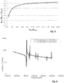
- Fig. 4 illustrates two exemplary graphs of such an impedance spectrum. It is remarked that the illustrated impedance spectra result from a mathematical simulation.
- a first graph is shown with a solid line and relates to a piezo actuator having a membrane that is 5 micron in thickness, has an effective length of 750 micron and an effective width of 144 micron.
- a second graph is shown with a dashed line and relates to a piezo actuator having a membrane that is 6 micron in thickness, has an effective length of 750 micron and an effective width of 160 micron.
- the effective length and the effective width of the membrane are the length and width used in the mathematical model to represent the flexible wall part of the membrane, i.e. the functional part of the membrane.
- the actual length and width may be slightly different depending on, amongst other aspects, the stiffness of the clamping of the membrane between the supply layer and the output layer.
- the membrane layer and the output layer such adhesive might be flexible such that the membrane may bend beyond a boundary of the pressure chamber.
- the effective length and the effective width may be larger than the actual length and the actual width of the pressure chamber, respectively.
- the first graph shows further resonance frequencies at 1.73 MHz, 2.10 MHz and 2.72 MHz.
- the second graph shows further resonance frequencies at 1.76 MHz, 2.22 MHz and 2.98 MHz.
- These resonance frequencies allow to determine the actuator compliance.
- the actuator properties define the resonance frequencies, taking other parameters of the actuator design as having a predetermined value, it is enabled to determine the actuator compliance from the resonance frequencies. Such method, of course, is only feasible if it is presumed that the other actuator properties have an actual value that is close to the presumed value. In another embodiment, it is considered to determine a value of one or more of such other actuator properties.
- the former provides a mathematical equation describing the impedance spectrum based on properties of the piezo material. Based on the mathematical equation, it appears that the actuator may be defined by three parameters and such three parameters are derivable from a measured impedance spectrum.
- the terms and phrases used herein are not intended to be limiting; but rather, to provide an understandable description of the invention.
- the terms "a” or “an”, as used herein, are defined as one or more than one.
- the term plurality, as used herein, is defined as two or more than two.
- the term another, as used herein, is defined as at least a second or more.
- the terms including and/or having, as used herein, are defined as comprising (i.e., open language).
- the term coupled, as used herein, is defined as connected, although not necessarily directly.
Description
- The present invention generally pertains to a piezo-actuated inkjet print head, a method of designing such a print head and a method for testing such a print head, wherein the print head is provided with a piezo actuator arranged for generating a pressure wave in a liquid in a pressure chamber such to expel a droplet of the liquid through a nozzle orifice.
- Inkjet print heads for generating and expelling droplets of fluid are well known in the art. A number of actuation methods are known to be employed in such print heads. In a known inkjet print head, a piezo stack, comprising a first electrode, a second electrode and a piezo-material layer therebetween, is driven to deform a flexible wall of a pressure chamber such that a pressure wave is generated in a fluid present in the pressure chamber. The pressure chamber is in fluid communication with a nozzle orifice of the print head and the pressure wave is such that a droplet of the fluid is expelled through the nozzle orifice.
- In order to actuate, a drive voltage is applied to the piezo stack, which piezo stack acts as a capacitor. Suitable drive circuitry supplies an actuation voltage and corresponding current. In order to generate and supply such drive voltage and current, power is consumed and heat is generated in the drive circuitry. In present inkjet print heads made using semiconductor technology (micro electromechanical systems (MEMS) technology) a high density arrangement of nozzle orifices and corresponding actuators is obtainable. However, in such high density arrangements and operating at a high frequency, a relatively large amount of heat is generated in the drive circuitry, including in any electrodes in the inkjet print head. A density of an arrangement of electrodes and a cross-section of each electrode (determining an electrical resistance in the electrodes) becomes limited due to which the design of such print heads. Further, due to heat generation in the voltage generating circuitry, incorporating the voltage generating circuitry in the inkjet print head is not feasible.
- It is advantageous to have a print head design in which a relatively low amount of heat is generated.
- In an aspect of the present invention, an inkjet print head is provided. The inkjet print head comprises a fluid channel for holding a channel amount of fluid. The fluid channel comprises a pressure chamber in fluid communication with the nozzle orifice. The inkjet print head further comprises a piezo actuator. The piezo actuator comprises an active piezo stack and a membrane. The active piezo stack comprises a first electrode, a second electrode, and a piezo-material layer arranged between the first and the second electrode. The membrane has a first side and a second side, the second side being opposite to the first side. The active piezo stack is provided at the first side of the membrane and the pressure chamber at the second side of the membrane such that the membrane forms a flexible wall of the pressure chamber. The piezo actuator is arranged on the membrane to deform by bending upon application of a voltage over the first electrode and the second electrode.
- The fluid channel, when holding the channel amount of fluid, has a fluid channel compliance and the piezo actuator has an actuator compliance. The fluid channel compliance has a number of contributions, inter alia from a compliance resulting from the amount of fluid present and a compliance resulting from the print head structure, including the compliance of the materials used. It is noted that the actuator compliance is not included in the fluid channel compliance; adding the actuator compliance and the fluid channel compliance results in a total system compliance or, in other words, the fluid channel compliance corresponds to the total system compliance minus the actuator compliance. In accordance with the present invention, the actuator compliance is larger than the fluid channel compliance. The actuator compliance is more than twice the fluid channel compliance.
-
JP2004-017612 - An acoustic design of a piezo-actuated inkjet print head is inter alia defined by an unloaded volume displacement of the actuator in response to a drive voltage and by the total system compliance. Such acoustic design determines the droplet generation, including a droplet generation frequency. When designing an inkjet print head and starting from print head requirements, an acoustic design may be selected. Then, in order to optimize an energy consumption without affecting the acoustic design, a ratio between the fluid channel compliance and the actuator compliance may be selected, provided that the total system compliance fits the acoustic design. As is described in more detail hereinbelow in relation to
Fig. 2 , an energy coupling coefficient indicating an energy efficiency of the print head acoustics, i.e. the droplet forming process, compared to the electrical energy input, is defined by
- Energy efficiency is improved if the energy coupling coefficient ECC is increased. Based on Eq. 1, it is apparent that the energy coupling coefficient ECCacoustics of the print head acoustics is increased when the actuator compliance Bact is selected to be higher than the fluid channel compliance Bchan. The term k2 is an actuator energy coupling coefficient that has a certain optimal value. Based on such optimal value, the actuator compliance Bact may be deemed defined. Therefore, in practice, it may be considered that designing the inkjet print head to have a relatively low fluid channel compliance compared to the actuator compliance is a well suited method for improving the energy efficiency. Using a relatively low fluid channel compliance, an energy coupling coefficient will be relatively high and consequently, an overall energy efficiency of the print head is improved. As a consequence, a low driving voltage / low current may be used for driving the print head and thus power dissipation in the drive circuitry is decreased. A method of designing a piezo-actuated inkjet print head having a fluid channel compliance significantly lower than an actuator compliance is another aspect of the present invention.
- As the actuator compliance is - in accordance with the present invention - a major contributor in the total system compliance, which has a significant contribution in defining the print head design, the actuator compliance is an important aspect to be accurately realized in an actual print head. In practice, a manufacturing accuracy of a large number of features influences the resulting actuator compliance and defining manufacturing tolerances for each of such features may result in very strict tolerances that increase the costs for the print head manufacturing or would even prohibit manufacturing as such strict tolerances may not be realistic. Therefore, it may be desirable to manufacture the inkjet print heads in large quantities using not so strict tolerances. Then, the actuator compliance of the resulting print heads may be determined. In many instances the inaccuracies in the manufacturing compensate each other resulting in a sufficient number of print heads meeting the requirements on actuator compliance. Discarding of the print heads that do not have an actuator compliance within a desired actuator compliance range may thus be more cost effective and realistic than posing very strict manufacturing accuracies. Moreover, for certain applications, a deviation from the originally defined compliance may be acceptable and a number of print heads having an actuator compliance deviating from the specified actuator compliance may be used for such applications, e.g. sorted based on their actual actuator compliance. In another embodiment, the actual actuator compliance may be compensated by an adapted drive voltage pulse. So, the determined actual compliance may be used to determine the adapted actuator voltage pulse.
- In such a manufacturing method, it is desired to have a simple and cost effective method of determining the actual actuator compliance. Therefore, in a further aspect, the present invention provides a method of testing a piezo-actuated print head for an actuator compliance and preferably also other actuator properties. The method includes the steps of performing impedance spectroscopy to determine an actuator impedance spectrum. Based on the impedance spectrum, an actual actuator compliance is derived. Then, the actual actuator compliance may be compared with a desired actuator compliance.
- Of course, such testing can be performed on only a part of the print head to be manufactured, if such a part comprises all elements needed to determine an impedance spectrum suitable for deriving the actuator compliance. So, at least the piezo-actuator comprising the active piezo-stack and the membrane needs to be comprised in such part of the print head. In this practical embodiment, if the actuator compliance is not within the desired actuator compliance range, only a part of the print head needs to be discarded instead of a whole print head.
- Based on the results of the testing of manufactured inkjet print heads, if too many print heads do not have an actuator in accordance with the desired specification of the actuator compliance, the manufacturing process parameters of one of the aspects affecting the actuator compliance may be adapted without determining which aspect actually deviates from the design. For example, if the actuator compliance is not within the desired actuator compliance range, a membrane thickness may be adapted such to adapt the actuator compliance without first determining why the actuator compliance is actually outside the desired actuator compliance range.
- Further scope of applicability of the present invention will become apparent from the detailed description given hereinafter. However, it should be understood that the detailed description and specific examples, while indicating embodiments of the invention, are given by way of illustration only, since various changes and modifications within the scope of the invention will become apparent to those skilled in the art from this detailed description.
- The present invention will become more fully understood from the detailed description given hereinbelow and the accompanying schematical drawings which are given by way of illustration only, and thus are not limitative of the present invention, and wherein:
- Fig. 1
- schematically illustrates an exemplary design of a piezo-actuated inkjet print head;
- Fig. 2
- illustrates a piezo-actuator as used in the print head according to
Fig. 1 ; and - Fig. 3
- shows a graph of an effect of the ratio between actuator compliance and fluid channel compliance; and
- Fig. 4
- shows a graph of an impedance spectrum obtained from a print head according to
Fig. 1 . - The present invention will now be described with reference to the accompanying drawings, wherein the same reference numerals have been used to identify the same or similar elements throughout the several views.
-
Fig. 1 shows an example of a design of a piezo-actuatedinkjet print head 1. Theinkjet print head 1 is formed by a three layered structure having asupply layer 11, amembrane layer 12 and anoutput layer 13. A fluid channel is composed of asupply channel 2, apressure chamber 3, anoutput channel 4a and anozzle orifice 4b. Themembrane layer 12 comprises apiezo actuator 5. The piezo actuator is formed by afirst electrode 51, apiezo material layer 52, asecond electrode 53 and amembrane 54. Thefirst electrode 51, thesecond electrode 53 and thepiezo material layer 52 arranged therebetween together form the active piezo stack. Upon application of a voltage over thefirst electrode 51 and thesecond electrode 53, an electrical field is provided in thepiezo material layer 52 and as a consequence thepiezo material layer 52 contracts or expands, in the present embodiment in a direction parallal to themembrane 54. As thepiezo material layer 52 is adhered tofirst electrode 51 and thesecond electrode 53 and indirectly to themembrane 54 and as at least themembrane 54 counteracts such contraction or expansion, thepiezo actuator 5 deforms by bending as illustrated in and described in relation toFig. 2 hereinbelow. - An actuation of the actuator generates a pressure wave in a fluid present in the fluid channel. The actuation and following pressure wave eventually induces a deformation of the
piezo actuator 5 and a corresponding volume change in the fluid channel, in particular in thepressure chamber 3. Thus, a suitably designed print head and a suitably generated pressure wave will result in a droplet being expelled through thenozzle orifice 4b, as is well known in the art. - The
supply layer 11 and theoutput layer 13 of theinkjet print head 1 may be formed from silicon wafers. The fluid channel may be formed in such silicon wafers by well known etching methods, for example. Using silicon wafers and etching techniques allows to generate relatively small structures such that a high density arrangement ofnozzle orifices 4b may be obtained. Thus, it may be possible to manufacture aninkjet print head 1 having a nozzle arrangement of 600 or even 1200 nozzles per inch (npi) that may be used in a printer assembly for printing at 600 or 1200 dots per inch (dpi), respectively. In a high density arrangement ofnozzle orifices 4b, there is of course also a high density of correspondingpiezo actuators 5. When operating theinkjet print head 1 drive circuitry generates an amount of heat due to power dissipation. For freedom of design, the power dissipation should be kept to a minimum. Therefore, a high energy efficiency is needed. A high energy efficiency may be achieved by obtaining a high energy coupling coefficient, i.e. a coefficient indicating a ratio of energy effectively used and energy input into the system. - In the field of piezo actuated inkjet print heads, an energy coupling coefficient of the electrical energy input and the energy effectively applied to the fluid, i.e. the acoustic energy, should be maximized for obtaining a high energy efficiency. Suitably designing the
inkjet print head 1 enables to obtain a high energy coupling coefficient. -
Fig. 2 shows theactuator 5 of theinkjet print head 1 ofFig. 1 in more detail. Adrive voltage source 6 is connected between thefirst electrode 51 and thesecond electrode 53. Thedrive voltage source 6 is configured for supplying a drive voltage U. The active piezo stack functions as a capacitor and consequently an electrical charge q will be supplied to thepiezo actuator 5 upon supply of the drive voltage U. Due to the piezo properties of thepiezo material layer 52 in response to the electrical field between thefirst electrode 51 and thesecond electrode 53, theactuator 5 will deform resulting in a shape of the membrane 54' (dashed). It is noted that the active piezo stack will of course deform to and remain on themembrane 54, but for clarity reasons the deformed active piezo stack is omitted inFig. 2 . Due to the deformation, a volume change V results in thepressure chamber 3. The fluid in thepressure chamber 3 exerts a pressure P. - Based on the above described and in
Fig. 2 illustrated structure and operation, a mathematical model describing the operation of the actuator may be defined:

- It is noted that Aact, Bact and Cact are not independent variables. Changing the actuator compliance Bact will affect the volume displacement Aact, for example. So, in practice, it has appeared that changing the parameters of the
actuator 5 within practical boundaries will not significantly affect the actuator energy coupling coefficient k2. Thus, a suitably designed actuator may be presumed to have a certain actuator energy coupling coefficient k2. Therefore, hereafter, the actuator energy coupling coefficient k2 is presumed to be a constant for the piezo actuatedinkjet print head 1. - Considering the mathematical model of the
actuator 5 and taking into account theprint head 1 as a whole, an acoustic energy coupling coefficient ECCacoustics describing the coupling between the electrical energy input and the effective acoustic energy is derivable:
- In practical situations, when designing the
inkjet print head 1 and in view of controlling actuator properties, the above conclusion may be realized by adapting the fluid channel compliance Bchan after the actuator compliance Bact has been determined and selected. Although adapting the actuator compliance may be suitable, it is noted that a change of the actuator compliance Bact may more impact on other aspects of the print head design. Adapting the fluid channel compliance Bchan may be achieved by adapting dimensions of thepressure chamber 3 considering that the fluid channel compliance Bchan has a large contribution from the compliance of the liquid present in thepressure chamber 3. While the length and width of thepressure chamber 3, i.e. the dimensions parallel to themembrane 54, have a direct relation to a membrane surface area and thus to the acoustic inkjet print head design, which should not be changed significantly to prevent changes in the acoustic design, the compliance of the liquid in thepressure chamber 3 is easily and effectively adapted by changing a depth, i.e. a dimension perpendicular to themembrane 54, of thepressure chamber 3. However, it is noted that other dimensions may be adapted such to change the fluid channel compliance, although in such case usually multiple dimensions need to be adapted to maintain the original acoustic design. -
Fig. 3 shows a graph that illustrates the influence of the ratio between the actuator compliance and the total compliance on the energy efficiency of the inkjet print head. The horizontal axis of the graph represents the ratio of the actuator compliance and the fluid channel compliance. The vertical axis represents the ratio of the actuator compliance and the total system compliance, which is a factor in the energy coupling coefficient as indicated in Eq. 1. This factor should be selected to be high. As is apparent from this graph, when the actuator compliance is lower than the fluid channel compliance, the ratio of the actuator compliance and the total system compliance is smaller than 0,5 and when the actuator compliance is equal to the fluid channel compliance, the ratio of the actuator compliance and the total system compliance is 0,5. Selecting the actuator compliance to be twice as large as the fluid channel compliance, the ratio between the actuator compliance and the total system compliance increases to 0,67, which amounts to an energy coupling coefficient improvement of 33% compared to the case where the actuator compliance and the fluid channel compliance are equal. In practice, it is feasible to select an actuator compliance to be as large as five times the fluid channel compliance - improvement of 67% compared to the case where the actuator compliance and the fluid channel compliance are equal - or even 10 times the fluid channel compliance - improvement of 82% compared to the case where the actuator compliance and the fluid channel compliance are equal. It is noted however that the sensitivity to deviations in the actuator compliance due to manufacturing tolerances becomes higher with increasing ratio of the actuator compliance and the fluid channel compliance, while the improvement of the energy coupling coefficient becomes minor. For example, a ratio of the actuator compliance over the fluid channel compliance of 10 results in an improvement of only 9% as compared to a ratio of 5. So, in practice, a ratio of the actuator compliance over the fluid channel compliance may be effectively selected to be in range of about 2 to about 10 and preferably in a range of about 3 to about 5. - As the actuator compliance Bact is relatively large and thus has a strong impact on the operation of an actual inkjet print head if the actual actuator compliance Bact deviates from a designed and desired actuator compliance B'act it is desired to be able to accurately control the manufacturing of the inkjet print head, in particular the
actuator 5. However, it has appeared that taking into account all potentially relevant features and their manufacturing tolerances it may be difficult and costly to have a suitable manufacturing method. Moreover, in many instances, the inaccuracies in manufacturing may, in practice, compensate each other. Therefore, manufacturing theactuator 5 in accordance with common and cost-effective methods and verifying the resulting actuator compliance Bact is a suitable method for manufacturing. - A method of manufacturing an inkjet print head in accordance with the present invention thus includes determining the actuator compliance Bact. The step of determining the actuator compliance Bact includes a step of performing impedance spectroscopy on a relevant part of the piezo-actuated inkjet print head to obtain an impedance spectrum of the actuator; and deriving from the impedance spectrum the actual actuator compliance. The actual actuator compliance may then be compared to the desired actuator compliance. It is noted that the impedance spectroscopy is a simple electrical measurement on the actuator. So, the measurement may be performed even before the actuator is adhered to other parts of the print head, depending on the specific method of manufacturing the print head.
-
Fig. 4 illustrates two exemplary graphs of such an impedance spectrum. It is remarked that the illustrated impedance spectra result from a mathematical simulation. A first graph is shown with a solid line and relates to a piezo actuator having a membrane that is 5 micron in thickness, has an effective length of 750 micron and an effective width of 144 micron. A second graph is shown with a dashed line and relates to a piezo actuator having a membrane that is 6 micron in thickness, has an effective length of 750 micron and an effective width of 160 micron. The effective length and the effective width of the membrane are the length and width used in the mathematical model to represent the flexible wall part of the membrane, i.e. the functional part of the membrane. In practice, the actual length and width may be slightly different depending on, amongst other aspects, the stiffness of the clamping of the membrane between the supply layer and the output layer. For example, if a relatively thick layer of adhesive would be used for joining the supply layer, the membrane layer and the output layer, such adhesive might be flexible such that the membrane may bend beyond a boundary of the pressure chamber. In such an example, the effective length and the effective width may be larger than the actual length and the actual width of the pressure chamber, respectively. Based on the graph, it is apparent that the membrane dimensions directly affect any resonance frequencies. The first graph shows four peaks, each indicating a resonance frequency. A first resonance frequency is for the first and the second graph about the same: 1.58 MHz. The first graph shows further resonance frequencies at 1.73 MHz, 2.10 MHz and 2.72 MHz. The second graph shows further resonance frequencies at 1.76 MHz, 2.22 MHz and 2.98 MHz. These resonance frequencies allow to determine the actuator compliance. As the actuator properties define the resonance frequencies, taking other parameters of the actuator design as having a predetermined value, it is enabled to determine the actuator compliance from the resonance frequencies. Such method, of course, is only feasible if it is presumed that the other actuator properties have an actual value that is close to the presumed value. In another embodiment, it is considered to determine a value of one or more of such other actuator properties. - In yet another embodiment, it is considered to employ a more detailed mathematical model that allows to determine a value for multiple parameters based on the results of the impedance spectrum. In accordance with common mathematical theory, there may be derived a value for as many parameters as there are independent input values. Whether it is actually feasible to derive a usable value for multiple parameters based on a determined number of independent resonance frequencies is however dependent on more aspects than mathematical theory only. For example, a relatively high noise level may result in such low accuracy that certain obtained values would not be useful. Defining and considering a suitable mathematical model for the inkjet print head acoustics and related calculations for deriving values of certain parameters from an impedance spectrum is deemed to be within the ambit of the person skilled in the art and is not further elucidated here.
- For more detailed discussion of properties and determining /measuring of such properties, reference is made to ANSI/IEEE Std 176-1987 and/or NEN-EN 50324-2:2002. For example, the former provides a mathematical equation describing the impedance spectrum based on properties of the piezo material. Based on the mathematical equation, it appears that the actuator may be defined by three parameters and such three parameters are derivable from a measured impedance spectrum.
- While detailed embodiments of the present invention are disclosed herein, it is to be understood that the disclosed embodiments are merely exemplary of the invention, which can be embodied in various forms. Therefore, specific structural and functional details disclosed herein are not to be interpreted as limiting, but merely as a basis for the claims and as a representative basis for teaching one skilled in the art to variously employ the present invention in virtually any appropriately detailed structure. In particular, features presented and described in separate dependent claims may be applied in combination and any advantageous combination of such claims are herewith disclosed.
- Further, the terms and phrases used herein are not intended to be limiting; but rather, to provide an understandable description of the invention. The terms "a" or "an", as used herein, are defined as one or more than one. The term plurality, as used herein, is defined as two or more than two. The term another, as used herein, is defined as at least a second or more. The terms including and/or having, as used herein, are defined as comprising (i.e., open language). The term coupled, as used herein, is defined as connected, although not necessarily directly.
Claims (5)
- Inkjet print head (1) for expelling a droplet of a fluid through a nozzle orifice, the inkjet print head (1) comprising• a fluid channel for holding a channel amount of fluid, the fluid channel comprising a pressure chamber (3) in fluid communication with the nozzle orifice;• a piezo actuator (5) comprising∘ an active piezo stack, comprising a first electrode (51), a second electrode (53), and a piezo-material layer (52) arranged between the first and the second electrode (51, 53);∘ a membrane (54) having a first side and a second side, the second side being opposite to the first side,∘ wherein the active piezo stack is provided at the first side of the membrane (54) and the pressure chamber (3) at the second side of the membrane (54) such that the membrane (54) forms a flexible wall of the pressure chamber (3), and∘ wherein the piezo actuator (5) is arranged on the membrane (54) to deform by bending upon application of a voltage over the first electrode (51) and the second electrode (53);wherein∘ the piezo actuator (5) has an actuator compliance;∘ the fluid channel, when holding the channel amount of fluid, has a fluid channel compliance,∘ the fluid channel compliance and the actuator compliance together form a total system compliance which corresponds to all compliances of the inkjet print head (1), and∘ the actuator compliance is more than twice the fluid channel compliance.
- The inkjet print head (1) according to claim 1, wherein the actuator compliance is more than five times the fluid channel compliance.
- Method of designing an piezo-actuated inkjet print head (1), wherein the piezo actuator (5) comprises:∘ an active piezo stack, comprising a first electrode (51), a second electrode (53), and a piezo-material layer (52) arranged between the first and the second electrode (51, 53);∘ a membrane (54) having a first side and a second side, the second side being opposite to the first side,∘ wherein the active piezo stack is provided at the first side of the membrane (54) and a pressure chamber (3) at the second side of the membrane (54) such that the membrane (54) forms a flexible wall of the pressure chamber (3), and∘ wherein the piezo-actuator (5) is arranged on the membrane (54) to deform by bending upon application of a voltage over the first electrode (51) and the second electrode (53);wherein the method comprises:• selecting an acoustic design, the acoustic design including an unloaded volume displacement of the piezo actuator (5) in response to a drive voltage and a total system compliance, which corresponds to all compliances of the inkjet print head (1);• selecting an actuator compliance and a fluid channel compliance, the actuator compliance corresponding to a compliance of the piezo actuator (5) and the fluid channel compliance corresponding to a compliance of a fluid channel, when holding a channel amount of fluid, the actuator compliance and the fluid channel compliance together forming the total system compliance;wherein the actuator compliance is selected to be more than twice the fluid channel compliance.
- Method according to claim 3, wherein the actuator compliance is selected to be more than five times the fluid channel compliance.
- Method of manufacturing a piezo-actuated print head (1) having been designed to have a desired actuator compliance, wherein the method comprises the steps of• manufacturing at least a part of an piezo-actuated inkjet print head (1) according to claim 1 or 2, wherein said part at least includes the piezo-actuator (5), the piezo-actuator comprising∘ an active piezo stack, comprising a first electrode (51), a second electrode (52), and a piezo-material (52) layer arranged between the first and the second electrode (51, 53);∘ a membrane (54), the active piezo stack being provided on a first side of the membrane (54);• performing impedance spectroscopy on the part of the piezo-actuated inkjet print head (1) to obtain an impedance spectrum;• deriving from the impedance spectrum an actual actuator compliance; and• comparing the actual actuator compliance with the desired actuator compliance.
Priority Applications (1)
| Application Number | Priority Date | Filing Date | Title |
|---|---|---|---|
| EP14744491.3A EP3024658B1 (en) | 2013-07-23 | 2014-07-16 | Piezo-actuated inkjet print head, method of designing such a print head and a method of manufacturing such a print head |
Applications Claiming Priority (3)
| Application Number | Priority Date | Filing Date | Title |
|---|---|---|---|
| EP13177581 | 2013-07-23 | ||
| PCT/EP2014/065230 WO2015010985A1 (en) | 2013-07-23 | 2014-07-16 | Piezo-actuated inkjet print head, method of designing such a print head and a method of manufacturing such a print head |
| EP14744491.3A EP3024658B1 (en) | 2013-07-23 | 2014-07-16 | Piezo-actuated inkjet print head, method of designing such a print head and a method of manufacturing such a print head |
Publications (2)
| Publication Number | Publication Date |
|---|---|
| EP3024658A1 EP3024658A1 (en) | 2016-06-01 |
| EP3024658B1 true EP3024658B1 (en) | 2019-06-05 |
Family
ID=48808247
Family Applications (1)
| Application Number | Title | Priority Date | Filing Date |
|---|---|---|---|
| EP14744491.3A Active EP3024658B1 (en) | 2013-07-23 | 2014-07-16 | Piezo-actuated inkjet print head, method of designing such a print head and a method of manufacturing such a print head |
Country Status (3)
| Country | Link |
|---|---|
| US (1) | US20160121611A1 (en) |
| EP (1) | EP3024658B1 (en) |
| WO (1) | WO2015010985A1 (en) |
Families Citing this family (6)
| Publication number | Priority date | Publication date | Assignee | Title |
|---|---|---|---|---|
| JP6828283B2 (en) * | 2016-06-22 | 2021-02-10 | セイコーエプソン株式会社 | Image recording method and inkjet ink composition |
| EP3275662B8 (en) | 2016-07-28 | 2021-01-20 | Canon Production Printing Holding B.V. | Method of manufacturing an inkjet print head |
| JP6844302B2 (en) * | 2017-02-22 | 2021-03-17 | セイコーエプソン株式会社 | Inkjet recording method and control method of inkjet recorder |
| US10712376B2 (en) * | 2018-03-29 | 2020-07-14 | Xerox Corporation | Impedance measurement of individual actuators of a piezoelectric print head |
| CN115279593A (en) * | 2020-03-30 | 2022-11-01 | 京瓷株式会社 | Liquid discharge head and recording apparatus |
| JP7474644B2 (en) * | 2020-06-18 | 2024-04-25 | 株式会社日立ハイテク | Automatic chemical analyzer and electrical impedance spectrometer |
Family Cites Families (5)
| Publication number | Priority date | Publication date | Assignee | Title |
|---|---|---|---|---|
| JP3503386B2 (en) * | 1996-01-26 | 2004-03-02 | セイコーエプソン株式会社 | Ink jet recording head and method of manufacturing the same |
| JP2003053966A (en) * | 2000-06-12 | 2003-02-26 | Seiko Epson Corp | Inkjet recording head |
| JP2003011362A (en) * | 2001-06-29 | 2003-01-15 | Toshiba Tec Corp | Ink jet printer and driving method for ink jet head |
| JP2004017612A (en) | 2002-06-20 | 2004-01-22 | Seiko Epson Corp | Liquid injection head and liquid injection device |
| JP2007049025A (en) * | 2005-08-11 | 2007-02-22 | Seiko Epson Corp | Actuator, liquid spray head and liquid spraying device |
-
2014
- 2014-07-16 WO PCT/EP2014/065230 patent/WO2015010985A1/en active Application Filing
- 2014-07-16 EP EP14744491.3A patent/EP3024658B1/en active Active
-
2016
- 2016-01-08 US US14/991,430 patent/US20160121611A1/en not_active Abandoned
Non-Patent Citations (1)
| Title |
|---|
| None * |
Also Published As
| Publication number | Publication date |
|---|---|
| WO2015010985A1 (en) | 2015-01-29 |
| US20160121611A1 (en) | 2016-05-05 |
| EP3024658A1 (en) | 2016-06-01 |
Similar Documents
| Publication | Publication Date | Title |
|---|---|---|
| EP3024658B1 (en) | Piezo-actuated inkjet print head, method of designing such a print head and a method of manufacturing such a print head | |
| US6676238B2 (en) | Driving method and apparatus for liquid discharge head | |
| JP6820704B2 (en) | Inkjet head drive device | |
| US10239313B2 (en) | Inkjet head drive apparatus | |
| US9421768B2 (en) | Inkjet printer head | |
| US10391768B2 (en) | Process of manufacturing droplet jetting devices | |
| JPWO2006137528A1 (en) | Driving method of liquid ejection device | |
| JP2016185685A (en) | Ink jet head driving device | |
| JP3480157B2 (en) | Actuator driving method and ink jet recording apparatus | |
| JP6879306B2 (en) | Inkjet head | |
| EP3275662B1 (en) | Method of manufacturing an inkjet print head | |
| US10780693B2 (en) | Inkjet head | |
| EP3083486B1 (en) | Mems chip and method of manufacturing a mems chip | |
| US6699018B2 (en) | Cell driving type micropump member and method for manufacturing the same | |
| US9682555B2 (en) | Inkjet print head with improved lifetime and efficiency | |
| JP2008023837A (en) | Droplet ejection apparatus | |
| EP0963843A2 (en) | Apparatus for jetting ink utilizing lamb wave and method for manufacturing the same | |
| WO2023233861A1 (en) | Inkjet head | |
| JPWO2009107552A1 (en) | Ink jet head and driving method thereof | |
| US10179451B2 (en) | Liquid ejection head and ink jet printer | |
| Rumschoettel et al. | Compact Model for the Static and Dynamic Behavior of a Piezoelectric Bimorph Actuator for Microfluidic MEMS | |
| WO2010146945A1 (en) | Inkjet head | |
| JP4187776B1 (en) | Ink jet head adhesion failure determination method, ink jet head manufacturing method, and image forming apparatus manufacturing method | |
| JP2004025890A (en) | Method for driving actuator, and inkjet recording device | |
| JP2006212972A (en) | Head for inkjet recording device |
Legal Events
| Date | Code | Title | Description |
|---|---|---|---|
| PUAI | Public reference made under article 153(3) epc to a published international application that has entered the european phase |
Free format text: ORIGINAL CODE: 0009012 |
|
| 17P | Request for examination filed |
Effective date: 20160223 |
|
| AK | Designated contracting states |
Kind code of ref document: A1 Designated state(s): AL AT BE BG CH CY CZ DE DK EE ES FI FR GB GR HR HU IE IS IT LI LT LU LV MC MK MT NL NO PL PT RO RS SE SI SK SM TR |
|
| AX | Request for extension of the european patent |
Extension state: BA ME |
|
| DAX | Request for extension of the european patent (deleted) | ||
| STAA | Information on the status of an ep patent application or granted ep patent |
Free format text: STATUS: EXAMINATION IS IN PROGRESS |
|
| 17Q | First examination report despatched |
Effective date: 20180312 |
|
| GRAP | Despatch of communication of intention to grant a patent |
Free format text: ORIGINAL CODE: EPIDOSNIGR1 |
|
| STAA | Information on the status of an ep patent application or granted ep patent |
Free format text: STATUS: GRANT OF PATENT IS INTENDED |
|
| GRAJ | Information related to disapproval of communication of intention to grant by the applicant or resumption of examination proceedings by the epo deleted |
Free format text: ORIGINAL CODE: EPIDOSDIGR1 |
|
| STAA | Information on the status of an ep patent application or granted ep patent |
Free format text: STATUS: EXAMINATION IS IN PROGRESS |
|
| INTG | Intention to grant announced |
Effective date: 20181205 |
|
| GRAP | Despatch of communication of intention to grant a patent |
Free format text: ORIGINAL CODE: EPIDOSNIGR1 |
|
| STAA | Information on the status of an ep patent application or granted ep patent |
Free format text: STATUS: GRANT OF PATENT IS INTENDED |
|
| INTG | Intention to grant announced |
Effective date: 20190107 |
|
| GRAS | Grant fee paid |
Free format text: ORIGINAL CODE: EPIDOSNIGR3 |
|
| GRAA | (expected) grant |
Free format text: ORIGINAL CODE: 0009210 |
|
| STAA | Information on the status of an ep patent application or granted ep patent |
Free format text: STATUS: THE PATENT HAS BEEN GRANTED |
|
| AK | Designated contracting states |
Kind code of ref document: B1 Designated state(s): AL AT BE BG CH CY CZ DE DK EE ES FI FR GB GR HR HU IE IS IT LI LT LU LV MC MK MT NL NO PL PT RO RS SE SI SK SM TR |
|
| REG | Reference to a national code |
Ref country code: GB Ref legal event code: FG4D |
|
| REG | Reference to a national code |
Ref country code: CH Ref legal event code: EP |
|
| REG | Reference to a national code |
Ref country code: AT Ref legal event code: REF Ref document number: 1139587 Country of ref document: AT Kind code of ref document: T Effective date: 20190615 |
|
| REG | Reference to a national code |
Ref country code: IE Ref legal event code: FG4D |
|
| REG | Reference to a national code |
Ref country code: DE Ref legal event code: R096 Ref document number: 602014047848 Country of ref document: DE |
|
| REG | Reference to a national code |
Ref country code: NL Ref legal event code: FP |
|
| REG | Reference to a national code |
Ref country code: LT Ref legal event code: MG4D |
|
| PG25 | Lapsed in a contracting state [announced via postgrant information from national office to epo] |
Ref country code: AL Free format text: LAPSE BECAUSE OF FAILURE TO SUBMIT A TRANSLATION OF THE DESCRIPTION OR TO PAY THE FEE WITHIN THE PRESCRIBED TIME-LIMIT Effective date: 20190605 Ref country code: ES Free format text: LAPSE BECAUSE OF FAILURE TO SUBMIT A TRANSLATION OF THE DESCRIPTION OR TO PAY THE FEE WITHIN THE PRESCRIBED TIME-LIMIT Effective date: 20190605 Ref country code: LT Free format text: LAPSE BECAUSE OF FAILURE TO SUBMIT A TRANSLATION OF THE DESCRIPTION OR TO PAY THE FEE WITHIN THE PRESCRIBED TIME-LIMIT Effective date: 20190605 Ref country code: FI Free format text: LAPSE BECAUSE OF FAILURE TO SUBMIT A TRANSLATION OF THE DESCRIPTION OR TO PAY THE FEE WITHIN THE PRESCRIBED TIME-LIMIT Effective date: 20190605 Ref country code: NO Free format text: LAPSE BECAUSE OF FAILURE TO SUBMIT A TRANSLATION OF THE DESCRIPTION OR TO PAY THE FEE WITHIN THE PRESCRIBED TIME-LIMIT Effective date: 20190905 Ref country code: SE Free format text: LAPSE BECAUSE OF FAILURE TO SUBMIT A TRANSLATION OF THE DESCRIPTION OR TO PAY THE FEE WITHIN THE PRESCRIBED TIME-LIMIT Effective date: 20190605 Ref country code: HR Free format text: LAPSE BECAUSE OF FAILURE TO SUBMIT A TRANSLATION OF THE DESCRIPTION OR TO PAY THE FEE WITHIN THE PRESCRIBED TIME-LIMIT Effective date: 20190605 |
|
| PG25 | Lapsed in a contracting state [announced via postgrant information from national office to epo] |
Ref country code: LV Free format text: LAPSE BECAUSE OF FAILURE TO SUBMIT A TRANSLATION OF THE DESCRIPTION OR TO PAY THE FEE WITHIN THE PRESCRIBED TIME-LIMIT Effective date: 20190605 Ref country code: BG Free format text: LAPSE BECAUSE OF FAILURE TO SUBMIT A TRANSLATION OF THE DESCRIPTION OR TO PAY THE FEE WITHIN THE PRESCRIBED TIME-LIMIT Effective date: 20190905 Ref country code: GR Free format text: LAPSE BECAUSE OF FAILURE TO SUBMIT A TRANSLATION OF THE DESCRIPTION OR TO PAY THE FEE WITHIN THE PRESCRIBED TIME-LIMIT Effective date: 20190906 Ref country code: RS Free format text: LAPSE BECAUSE OF FAILURE TO SUBMIT A TRANSLATION OF THE DESCRIPTION OR TO PAY THE FEE WITHIN THE PRESCRIBED TIME-LIMIT Effective date: 20190605 |
|
| REG | Reference to a national code |
Ref country code: AT Ref legal event code: MK05 Ref document number: 1139587 Country of ref document: AT Kind code of ref document: T Effective date: 20190605 |
|
| PG25 | Lapsed in a contracting state [announced via postgrant information from national office to epo] |
Ref country code: PT Free format text: LAPSE BECAUSE OF FAILURE TO SUBMIT A TRANSLATION OF THE DESCRIPTION OR TO PAY THE FEE WITHIN THE PRESCRIBED TIME-LIMIT Effective date: 20191007 Ref country code: RO Free format text: LAPSE BECAUSE OF FAILURE TO SUBMIT A TRANSLATION OF THE DESCRIPTION OR TO PAY THE FEE WITHIN THE PRESCRIBED TIME-LIMIT Effective date: 20190605 Ref country code: AT Free format text: LAPSE BECAUSE OF FAILURE TO SUBMIT A TRANSLATION OF THE DESCRIPTION OR TO PAY THE FEE WITHIN THE PRESCRIBED TIME-LIMIT Effective date: 20190605 Ref country code: CZ Free format text: LAPSE BECAUSE OF FAILURE TO SUBMIT A TRANSLATION OF THE DESCRIPTION OR TO PAY THE FEE WITHIN THE PRESCRIBED TIME-LIMIT Effective date: 20190605 Ref country code: EE Free format text: LAPSE BECAUSE OF FAILURE TO SUBMIT A TRANSLATION OF THE DESCRIPTION OR TO PAY THE FEE WITHIN THE PRESCRIBED TIME-LIMIT Effective date: 20190605 Ref country code: SK Free format text: LAPSE BECAUSE OF FAILURE TO SUBMIT A TRANSLATION OF THE DESCRIPTION OR TO PAY THE FEE WITHIN THE PRESCRIBED TIME-LIMIT Effective date: 20190605 |
|
| PG25 | Lapsed in a contracting state [announced via postgrant information from national office to epo] |
Ref country code: IT Free format text: LAPSE BECAUSE OF FAILURE TO SUBMIT A TRANSLATION OF THE DESCRIPTION OR TO PAY THE FEE WITHIN THE PRESCRIBED TIME-LIMIT Effective date: 20190605 Ref country code: IS Free format text: LAPSE BECAUSE OF FAILURE TO SUBMIT A TRANSLATION OF THE DESCRIPTION OR TO PAY THE FEE WITHIN THE PRESCRIBED TIME-LIMIT Effective date: 20191005 Ref country code: SM Free format text: LAPSE BECAUSE OF FAILURE TO SUBMIT A TRANSLATION OF THE DESCRIPTION OR TO PAY THE FEE WITHIN THE PRESCRIBED TIME-LIMIT Effective date: 20190605 |
|
| REG | Reference to a national code |
Ref country code: CH Ref legal event code: PL |
|
| REG | Reference to a national code |
Ref country code: DE Ref legal event code: R097 Ref document number: 602014047848 Country of ref document: DE |
|
| PG25 | Lapsed in a contracting state [announced via postgrant information from national office to epo] |
Ref country code: TR Free format text: LAPSE BECAUSE OF FAILURE TO SUBMIT A TRANSLATION OF THE DESCRIPTION OR TO PAY THE FEE WITHIN THE PRESCRIBED TIME-LIMIT Effective date: 20190605 Ref country code: MC Free format text: LAPSE BECAUSE OF FAILURE TO SUBMIT A TRANSLATION OF THE DESCRIPTION OR TO PAY THE FEE WITHIN THE PRESCRIBED TIME-LIMIT Effective date: 20190605 |
|
| PLBE | No opposition filed within time limit |
Free format text: ORIGINAL CODE: 0009261 |
|
| STAA | Information on the status of an ep patent application or granted ep patent |
Free format text: STATUS: NO OPPOSITION FILED WITHIN TIME LIMIT |
|
| REG | Reference to a national code |
Ref country code: BE Ref legal event code: MM Effective date: 20190731 |
|
| PG25 | Lapsed in a contracting state [announced via postgrant information from national office to epo] |
Ref country code: DK Free format text: LAPSE BECAUSE OF FAILURE TO SUBMIT A TRANSLATION OF THE DESCRIPTION OR TO PAY THE FEE WITHIN THE PRESCRIBED TIME-LIMIT Effective date: 20190605 Ref country code: PL Free format text: LAPSE BECAUSE OF FAILURE TO SUBMIT A TRANSLATION OF THE DESCRIPTION OR TO PAY THE FEE WITHIN THE PRESCRIBED TIME-LIMIT Effective date: 20190605 |
|
| 26N | No opposition filed |
Effective date: 20200306 |
|
| PG25 | Lapsed in a contracting state [announced via postgrant information from national office to epo] |
Ref country code: SI Free format text: LAPSE BECAUSE OF FAILURE TO SUBMIT A TRANSLATION OF THE DESCRIPTION OR TO PAY THE FEE WITHIN THE PRESCRIBED TIME-LIMIT Effective date: 20190605 Ref country code: BE Free format text: LAPSE BECAUSE OF NON-PAYMENT OF DUE FEES Effective date: 20190731 Ref country code: LU Free format text: LAPSE BECAUSE OF NON-PAYMENT OF DUE FEES Effective date: 20190716 Ref country code: LI Free format text: LAPSE BECAUSE OF NON-PAYMENT OF DUE FEES Effective date: 20190731 Ref country code: CH Free format text: LAPSE BECAUSE OF NON-PAYMENT OF DUE FEES Effective date: 20190731 |
|
| PG25 | Lapsed in a contracting state [announced via postgrant information from national office to epo] |
Ref country code: IE Free format text: LAPSE BECAUSE OF NON-PAYMENT OF DUE FEES Effective date: 20190716 |
|
| PG25 | Lapsed in a contracting state [announced via postgrant information from national office to epo] |
Ref country code: CY Free format text: LAPSE BECAUSE OF FAILURE TO SUBMIT A TRANSLATION OF THE DESCRIPTION OR TO PAY THE FEE WITHIN THE PRESCRIBED TIME-LIMIT Effective date: 20190605 |
|
| PG25 | Lapsed in a contracting state [announced via postgrant information from national office to epo] |
Ref country code: HU Free format text: LAPSE BECAUSE OF FAILURE TO SUBMIT A TRANSLATION OF THE DESCRIPTION OR TO PAY THE FEE WITHIN THE PRESCRIBED TIME-LIMIT; INVALID AB INITIO Effective date: 20140716 Ref country code: MT Free format text: LAPSE BECAUSE OF FAILURE TO SUBMIT A TRANSLATION OF THE DESCRIPTION OR TO PAY THE FEE WITHIN THE PRESCRIBED TIME-LIMIT Effective date: 20190605 |
|
| PG25 | Lapsed in a contracting state [announced via postgrant information from national office to epo] |
Ref country code: MK Free format text: LAPSE BECAUSE OF FAILURE TO SUBMIT A TRANSLATION OF THE DESCRIPTION OR TO PAY THE FEE WITHIN THE PRESCRIBED TIME-LIMIT Effective date: 20190605 |
|
| PGFP | Annual fee paid to national office [announced via postgrant information from national office to epo] |
Ref country code: NL Payment date: 20230621 Year of fee payment: 10 |
|
| PGFP | Annual fee paid to national office [announced via postgrant information from national office to epo] |
Ref country code: GB Payment date: 20230721 Year of fee payment: 10 |
|
| PGFP | Annual fee paid to national office [announced via postgrant information from national office to epo] |
Ref country code: FR Payment date: 20230726 Year of fee payment: 10 Ref country code: DE Payment date: 20230719 Year of fee payment: 10 |