EP3024648B1 - Metal and graphite laminate - Google Patents
Metal and graphite laminate Download PDFInfo
- Publication number
- EP3024648B1 EP3024648B1 EP14828679.2A EP14828679A EP3024648B1 EP 3024648 B1 EP3024648 B1 EP 3024648B1 EP 14828679 A EP14828679 A EP 14828679A EP 3024648 B1 EP3024648 B1 EP 3024648B1
- Authority
- EP
- European Patent Office
- Prior art keywords
- layer
- graphite foil
- shim
- piercing
- graphite
- Prior art date
- Legal status (The legal status is an assumption and is not a legal conclusion. Google has not performed a legal analysis and makes no representation as to the accuracy of the status listed.)
- Not-in-force
Links
Images


Classifications
-
- B—PERFORMING OPERATIONS; TRANSPORTING
- B32—LAYERED PRODUCTS
- B32B—LAYERED PRODUCTS, i.e. PRODUCTS BUILT-UP OF STRATA OF FLAT OR NON-FLAT, e.g. CELLULAR OR HONEYCOMB, FORM
- B32B9/00—Layered products comprising a layer of a particular substance not covered by groups B32B11/00 - B32B29/00
- B32B9/005—Layered products comprising a layer of a particular substance not covered by groups B32B11/00 - B32B29/00 comprising one layer of ceramic material, e.g. porcelain, ceramic tile
- B32B9/007—Layered products comprising a layer of a particular substance not covered by groups B32B11/00 - B32B29/00 comprising one layer of ceramic material, e.g. porcelain, ceramic tile comprising carbon, e.g. graphite, composite carbon
-
- B—PERFORMING OPERATIONS; TRANSPORTING
- B32—LAYERED PRODUCTS
- B32B—LAYERED PRODUCTS, i.e. PRODUCTS BUILT-UP OF STRATA OF FLAT OR NON-FLAT, e.g. CELLULAR OR HONEYCOMB, FORM
- B32B15/00—Layered products comprising a layer of metal
- B32B15/18—Layered products comprising a layer of metal comprising iron or steel
-
- B—PERFORMING OPERATIONS; TRANSPORTING
- B32—LAYERED PRODUCTS
- B32B—LAYERED PRODUCTS, i.e. PRODUCTS BUILT-UP OF STRATA OF FLAT OR NON-FLAT, e.g. CELLULAR OR HONEYCOMB, FORM
- B32B3/00—Layered products comprising a layer with external or internal discontinuities or unevennesses, or a layer of non-planar shape; Layered products comprising a layer having particular features of form
- B32B3/26—Layered products comprising a layer with external or internal discontinuities or unevennesses, or a layer of non-planar shape; Layered products comprising a layer having particular features of form characterised by a particular shape of the outline of the cross-section of a continuous layer; characterised by a layer with cavities or internal voids ; characterised by an apertured layer
- B32B3/266—Layered products comprising a layer with external or internal discontinuities or unevennesses, or a layer of non-planar shape; Layered products comprising a layer having particular features of form characterised by a particular shape of the outline of the cross-section of a continuous layer; characterised by a layer with cavities or internal voids ; characterised by an apertured layer characterised by an apertured layer, the apertures going through the whole thickness of the layer, e.g. expanded metal, perforated layer, slit layer regular cells B32B3/12
-
- B—PERFORMING OPERATIONS; TRANSPORTING
- B32—LAYERED PRODUCTS
- B32B—LAYERED PRODUCTS, i.e. PRODUCTS BUILT-UP OF STRATA OF FLAT OR NON-FLAT, e.g. CELLULAR OR HONEYCOMB, FORM
- B32B3/00—Layered products comprising a layer with external or internal discontinuities or unevennesses, or a layer of non-planar shape; Layered products comprising a layer having particular features of form
- B32B3/26—Layered products comprising a layer with external or internal discontinuities or unevennesses, or a layer of non-planar shape; Layered products comprising a layer having particular features of form characterised by a particular shape of the outline of the cross-section of a continuous layer; characterised by a layer with cavities or internal voids ; characterised by an apertured layer
- B32B3/30—Layered products comprising a layer with external or internal discontinuities or unevennesses, or a layer of non-planar shape; Layered products comprising a layer having particular features of form characterised by a particular shape of the outline of the cross-section of a continuous layer; characterised by a layer with cavities or internal voids ; characterised by an apertured layer characterised by a layer formed with recesses or projections, e.g. hollows, grooves, protuberances, ribs
-
- B—PERFORMING OPERATIONS; TRANSPORTING
- B32—LAYERED PRODUCTS
- B32B—LAYERED PRODUCTS, i.e. PRODUCTS BUILT-UP OF STRATA OF FLAT OR NON-FLAT, e.g. CELLULAR OR HONEYCOMB, FORM
- B32B7/00—Layered products characterised by the relation between layers; Layered products characterised by the relative orientation of features between layers, or by the relative values of a measurable parameter between layers, i.e. products comprising layers having different physical, chemical or physicochemical properties; Layered products characterised by the interconnection of layers
- B32B7/04—Interconnection of layers
- B32B7/08—Interconnection of layers by mechanical means
-
- B—PERFORMING OPERATIONS; TRANSPORTING
- B32—LAYERED PRODUCTS
- B32B—LAYERED PRODUCTS, i.e. PRODUCTS BUILT-UP OF STRATA OF FLAT OR NON-FLAT, e.g. CELLULAR OR HONEYCOMB, FORM
- B32B9/00—Layered products comprising a layer of a particular substance not covered by groups B32B11/00 - B32B29/00
- B32B9/04—Layered products comprising a layer of a particular substance not covered by groups B32B11/00 - B32B29/00 comprising such particular substance as the main or only constituent of a layer, which is next to another layer of the same or of a different material
- B32B9/041—Layered products comprising a layer of a particular substance not covered by groups B32B11/00 - B32B29/00 comprising such particular substance as the main or only constituent of a layer, which is next to another layer of the same or of a different material of metal
-
- F—MECHANICAL ENGINEERING; LIGHTING; HEATING; WEAPONS; BLASTING
- F16—ENGINEERING ELEMENTS AND UNITS; GENERAL MEASURES FOR PRODUCING AND MAINTAINING EFFECTIVE FUNCTIONING OF MACHINES OR INSTALLATIONS; THERMAL INSULATION IN GENERAL
- F16D—COUPLINGS FOR TRANSMITTING ROTATION; CLUTCHES; BRAKES
- F16D65/00—Parts or details
- F16D65/0006—Noise or vibration control
-
- F—MECHANICAL ENGINEERING; LIGHTING; HEATING; WEAPONS; BLASTING
- F16—ENGINEERING ELEMENTS AND UNITS; GENERAL MEASURES FOR PRODUCING AND MAINTAINING EFFECTIVE FUNCTIONING OF MACHINES OR INSTALLATIONS; THERMAL INSULATION IN GENERAL
- F16D—COUPLINGS FOR TRANSMITTING ROTATION; CLUTCHES; BRAKES
- F16D65/00—Parts or details
- F16D65/02—Braking members; Mounting thereof
- F16D65/04—Bands, shoes or pads; Pivots or supporting members therefor
- F16D65/092—Bands, shoes or pads; Pivots or supporting members therefor for axially-engaging brakes, e.g. disc brakes
- F16D65/095—Pivots or supporting members therefor
- F16D65/097—Resilient means interposed between pads and supporting members or other brake parts
- F16D65/0971—Resilient means interposed between pads and supporting members or other brake parts transmitting brake actuation force, e.g. elements interposed between brake piston and pad
-
- F—MECHANICAL ENGINEERING; LIGHTING; HEATING; WEAPONS; BLASTING
- F16—ENGINEERING ELEMENTS AND UNITS; GENERAL MEASURES FOR PRODUCING AND MAINTAINING EFFECTIVE FUNCTIONING OF MACHINES OR INSTALLATIONS; THERMAL INSULATION IN GENERAL
- F16J—PISTONS; CYLINDERS; SEALINGS
- F16J15/00—Sealings
- F16J15/02—Sealings between relatively-stationary surfaces
- F16J15/06—Sealings between relatively-stationary surfaces with solid packing compressed between sealing surfaces
- F16J15/10—Sealings between relatively-stationary surfaces with solid packing compressed between sealing surfaces with non-metallic packing
- F16J15/12—Sealings between relatively-stationary surfaces with solid packing compressed between sealing surfaces with non-metallic packing with metal reinforcement or covering
- F16J15/121—Sealings between relatively-stationary surfaces with solid packing compressed between sealing surfaces with non-metallic packing with metal reinforcement or covering with metal reinforcement
- F16J15/122—Sealings between relatively-stationary surfaces with solid packing compressed between sealing surfaces with non-metallic packing with metal reinforcement or covering with metal reinforcement generally parallel to the surfaces
-
- B—PERFORMING OPERATIONS; TRANSPORTING
- B32—LAYERED PRODUCTS
- B32B—LAYERED PRODUCTS, i.e. PRODUCTS BUILT-UP OF STRATA OF FLAT OR NON-FLAT, e.g. CELLULAR OR HONEYCOMB, FORM
- B32B2307/00—Properties of the layers or laminate
- B32B2307/10—Properties of the layers or laminate having particular acoustical properties
- B32B2307/102—Insulating
-
- B—PERFORMING OPERATIONS; TRANSPORTING
- B32—LAYERED PRODUCTS
- B32B—LAYERED PRODUCTS, i.e. PRODUCTS BUILT-UP OF STRATA OF FLAT OR NON-FLAT, e.g. CELLULAR OR HONEYCOMB, FORM
- B32B2307/00—Properties of the layers or laminate
- B32B2307/50—Properties of the layers or laminate having particular mechanical properties
- B32B2307/536—Hardness
-
- B—PERFORMING OPERATIONS; TRANSPORTING
- B32—LAYERED PRODUCTS
- B32B—LAYERED PRODUCTS, i.e. PRODUCTS BUILT-UP OF STRATA OF FLAT OR NON-FLAT, e.g. CELLULAR OR HONEYCOMB, FORM
- B32B2307/00—Properties of the layers or laminate
- B32B2307/50—Properties of the layers or laminate having particular mechanical properties
- B32B2307/54—Yield strength; Tensile strength
-
- B—PERFORMING OPERATIONS; TRANSPORTING
- B32—LAYERED PRODUCTS
- B32B—LAYERED PRODUCTS, i.e. PRODUCTS BUILT-UP OF STRATA OF FLAT OR NON-FLAT, e.g. CELLULAR OR HONEYCOMB, FORM
- B32B2307/00—Properties of the layers or laminate
- B32B2307/50—Properties of the layers or laminate having particular mechanical properties
- B32B2307/56—Damping, energy absorption
-
- B—PERFORMING OPERATIONS; TRANSPORTING
- B32—LAYERED PRODUCTS
- B32B—LAYERED PRODUCTS, i.e. PRODUCTS BUILT-UP OF STRATA OF FLAT OR NON-FLAT, e.g. CELLULAR OR HONEYCOMB, FORM
- B32B2475/00—Frictional elements
-
- B—PERFORMING OPERATIONS; TRANSPORTING
- B32—LAYERED PRODUCTS
- B32B—LAYERED PRODUCTS, i.e. PRODUCTS BUILT-UP OF STRATA OF FLAT OR NON-FLAT, e.g. CELLULAR OR HONEYCOMB, FORM
- B32B2605/00—Vehicles
-
- F—MECHANICAL ENGINEERING; LIGHTING; HEATING; WEAPONS; BLASTING
- F16—ENGINEERING ELEMENTS AND UNITS; GENERAL MEASURES FOR PRODUCING AND MAINTAINING EFFECTIVE FUNCTIONING OF MACHINES OR INSTALLATIONS; THERMAL INSULATION IN GENERAL
- F16D—COUPLINGS FOR TRANSMITTING ROTATION; CLUTCHES; BRAKES
- F16D2200/00—Materials; Production methods therefor
- F16D2200/0004—Materials; Production methods therefor metallic
- F16D2200/0008—Ferro
- F16D2200/0021—Steel
-
- F—MECHANICAL ENGINEERING; LIGHTING; HEATING; WEAPONS; BLASTING
- F16—ENGINEERING ELEMENTS AND UNITS; GENERAL MEASURES FOR PRODUCING AND MAINTAINING EFFECTIVE FUNCTIONING OF MACHINES OR INSTALLATIONS; THERMAL INSULATION IN GENERAL
- F16D—COUPLINGS FOR TRANSMITTING ROTATION; CLUTCHES; BRAKES
- F16D2200/00—Materials; Production methods therefor
- F16D2200/0034—Materials; Production methods therefor non-metallic
-
- F—MECHANICAL ENGINEERING; LIGHTING; HEATING; WEAPONS; BLASTING
- F16—ENGINEERING ELEMENTS AND UNITS; GENERAL MEASURES FOR PRODUCING AND MAINTAINING EFFECTIVE FUNCTIONING OF MACHINES OR INSTALLATIONS; THERMAL INSULATION IN GENERAL
- F16D—COUPLINGS FOR TRANSMITTING ROTATION; CLUTCHES; BRAKES
- F16D2200/00—Materials; Production methods therefor
- F16D2200/0034—Materials; Production methods therefor non-metallic
- F16D2200/0052—Carbon
-
- Y—GENERAL TAGGING OF NEW TECHNOLOGICAL DEVELOPMENTS; GENERAL TAGGING OF CROSS-SECTIONAL TECHNOLOGIES SPANNING OVER SEVERAL SECTIONS OF THE IPC; TECHNICAL SUBJECTS COVERED BY FORMER USPC CROSS-REFERENCE ART COLLECTIONS [XRACs] AND DIGESTS
- Y10—TECHNICAL SUBJECTS COVERED BY FORMER USPC
- Y10T—TECHNICAL SUBJECTS COVERED BY FORMER US CLASSIFICATION
- Y10T428/00—Stock material or miscellaneous articles
- Y10T428/24—Structurally defined web or sheet [e.g., overall dimension, etc.]
- Y10T428/24273—Structurally defined web or sheet [e.g., overall dimension, etc.] including aperture
- Y10T428/24281—Struck out portion type
- Y10T428/24289—Embedded or interlocked
-
- Y—GENERAL TAGGING OF NEW TECHNOLOGICAL DEVELOPMENTS; GENERAL TAGGING OF CROSS-SECTIONAL TECHNOLOGIES SPANNING OVER SEVERAL SECTIONS OF THE IPC; TECHNICAL SUBJECTS COVERED BY FORMER USPC CROSS-REFERENCE ART COLLECTIONS [XRACs] AND DIGESTS
- Y10—TECHNICAL SUBJECTS COVERED BY FORMER USPC
- Y10T—TECHNICAL SUBJECTS COVERED BY FORMER US CLASSIFICATION
- Y10T428/00—Stock material or miscellaneous articles
- Y10T428/24—Structurally defined web or sheet [e.g., overall dimension, etc.]
- Y10T428/24273—Structurally defined web or sheet [e.g., overall dimension, etc.] including aperture
- Y10T428/24322—Composite web or sheet
- Y10T428/24331—Composite web or sheet including nonapertured component
- Y10T428/24339—Keyed
-
- Y—GENERAL TAGGING OF NEW TECHNOLOGICAL DEVELOPMENTS; GENERAL TAGGING OF CROSS-SECTIONAL TECHNOLOGIES SPANNING OVER SEVERAL SECTIONS OF THE IPC; TECHNICAL SUBJECTS COVERED BY FORMER USPC CROSS-REFERENCE ART COLLECTIONS [XRACs] AND DIGESTS
- Y10—TECHNICAL SUBJECTS COVERED BY FORMER USPC
- Y10T—TECHNICAL SUBJECTS COVERED BY FORMER US CLASSIFICATION
- Y10T428/00—Stock material or miscellaneous articles
- Y10T428/24—Structurally defined web or sheet [e.g., overall dimension, etc.]
- Y10T428/24479—Structurally defined web or sheet [e.g., overall dimension, etc.] including variation in thickness
- Y10T428/24521—Structurally defined web or sheet [e.g., overall dimension, etc.] including variation in thickness with component conforming to contour of nonplanar surface
- Y10T428/24529—Structurally defined web or sheet [e.g., overall dimension, etc.] including variation in thickness with component conforming to contour of nonplanar surface and conforming component on an opposite nonplanar surface
-
- Y—GENERAL TAGGING OF NEW TECHNOLOGICAL DEVELOPMENTS; GENERAL TAGGING OF CROSS-SECTIONAL TECHNOLOGIES SPANNING OVER SEVERAL SECTIONS OF THE IPC; TECHNICAL SUBJECTS COVERED BY FORMER USPC CROSS-REFERENCE ART COLLECTIONS [XRACs] AND DIGESTS
- Y10—TECHNICAL SUBJECTS COVERED BY FORMER USPC
- Y10T—TECHNICAL SUBJECTS COVERED BY FORMER US CLASSIFICATION
- Y10T428/00—Stock material or miscellaneous articles
- Y10T428/24—Structurally defined web or sheet [e.g., overall dimension, etc.]
- Y10T428/24479—Structurally defined web or sheet [e.g., overall dimension, etc.] including variation in thickness
- Y10T428/24521—Structurally defined web or sheet [e.g., overall dimension, etc.] including variation in thickness with component conforming to contour of nonplanar surface
- Y10T428/24545—Containing metal or metal compound
Definitions
- the present invention relates generally to laminated materials, and more particularly to laminated materials comprising at least one textured metal sheet layer bound to at least one graphite foil layer.
- Stainless steel laminated with graphite foil is a widely used material that has properties that make it suitable for many purposes, such as making gaskets. Such gaskets can provide high blowout resistance and so can be used in applications with high sealing stresses. Such material is permanently elastic over a wide temperature range, such as - 200°C to 550°C. It does not age, is not brittle and provides long-term uniformity and resiliency independent of temperature so that is can withstand high compressive stresses. It can also tolerate high pressure, such as up to 500 bar.
- the steel, or “carrier”, layer is typically a 0.10 - 0.12 mm thick sheet of "tanged" stainless steel.
- the laminate is then formed by pressing a sheet of graphite foil onto each surface of the metal sheet to create a laminate with a thickness typically of I to 4 mm.
- the use of tanged metal allows the layers to bind mechanically, without the need for any adhesive, as the tangs on each surface of the metal penetrate into the graphite foil pressed on each surface.
- Such tanged metal sheeting is formed by a metal foil puncher, which employs needles that perforate the foil, causing tangs to extend from the side of the sheet opposite the side that the needle penetrates. As a result, the sheeting is weakened by the perforations. Also, if the metal sheet is only laminated on one side, the unlaminated metal surface is not smooth because of the perforations. Furthermore, the thickness of the metal layer is limited because it must be thin enough to allow the puncher needles to penetrate it. It would be desirable to provide a material having graphite foil laminated on at least one side that does not suffer from the disadvantages resulting from the use of such tanged metal.
- a hydraulically actuated piston forces, by action and reaction, a pair of opposing brake pads to pinch a rotor attached to a vehicle wheel.
- Brake pads have a stiff backing plate with friction pads affixed to one side. Shims of a thin material are often used on the side of the plate contacted by the piston.
- the shim's function is to reduce the frequency of occurrence of a loud and annoying squeal noise from what are otherwise mechanically perfect brakes. At least some of the noise comes from the fact that, to prevent jamming, the plate has some freedom of radial movement within the caliper so that the rotor can be freed, while the piston has little freedom of movement.
- the rigid rotor In braking, the rigid rotor is frictionally engaged by the hard brake pad (which is in turn supported by its hard backing plate).
- the brake pad can frictionally slide to some degree against the rigid piston and caliper. High frictional forces are generated during this sliding movement which can cause squeal. Like a stick of chalk forced at an angle across a rigid board, friction can lead to very severe vibrational noise. As well, these recurring forces can lead to fretting and chipping of the piston rim. Brake squeal is a very expensive problem for car and brake manufacturers as customers invariably want the noise remedied under warranty even if the brakes are otherwise perfect.
- Document JP S59 174431 discloses a method for damping brake noise, comprising installing a metal-graphite laminate brake pad shim between a brake piston and a brake pad, wherein the metal-graphite laminate brake pad shim comprises a first lamina of a metal and a second lamina of a graphite foil material, the first lamina having a plurality of piercing structures extending therefrom and piercing the second lamina.
- US 5,788,247 discloses a composite material gasket comprising a core layer made of multiple layers forming a sheet-like structure, i.e. a non-unitary panel of metal which is unsuitable for use in brake pad shims.
- US 5,172,920 teaches a composite material for a gasket, including a perforated metal core sheet sandwiched between facing layers.
- a noise damping shim as set forth in claim 1 including a three layer laminate comprising:
- a method for damping brake noise comprising installing the noise damping shim of claim 1 between a brake piston and a brake pad backing plate.
- Clinching (clinching, clinchable, clinched), is used to describe the act of bending over the exposed apex portion or "tip" of a pin- or nail-like structure that has pierced through two or more layers and extends therefrom.
- Clinching is common practice in the wood construction trade. Clinching is analogous to riveting in metal work, or to any other deformation of a fastener to prevent its easy withdrawal. The purpose of clinching is to impart greater cohesion between the two laminate layers that are so joined.
- pointed structure and "piercing structure” are used synonymously herein as a general term to describe any type of nail- or pin-like structure (or hooked or barbed structure) raised on the surface of a material (for embedding or piercing) that are capable of piercing and then penetrating the surface of a graphite foil.
- An appropriate choice of hardness of the material and shape and configuration of the piercing structures is selected to ensure such piercing capability.
- piercing structures have been raised from a surface of a lamina consisting of relatively hard material, such as a sheet of stainless steel. They can pierce into the inner surface of an adjacent graphite foil lamina and, if longer than the graphite foil's thickness, can protrude through the outer surface of the foil.
- the protruding tips may be bent over or clinched to create the "locked-laminate" embodiment of the instant invention.
- the surface, or face, of the first lamina that is mated to the other lamina is referred to as the inner surface, and the other surface, which is not mated with another lamina, is referred to as the outer surface.
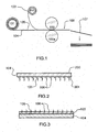
- Figure 1 shows a process for making a continuous laminated metal and graphite material.
- Coil 101 supplies the first lamina of textured metal 104 having one face textured with piercing structures 105 having pointed tips 106.
- Coil 102 supplies the second lamina of graphite foil 103.
- the two lamina layers are fed between pressure rolls 100, 100a. Under pressure from rolls 100, 100a, the inner surfaces of the two laminae are forced together so that some, or preferably most or all of the piercing structures of the textured metal sheet 104 penetrate through the lower surface of the graphite foil 103. They may not pierce the upper surface of the graphite foil 103, as in Figure 1 .
- the piercing structures of the textured metal sheet 104 may penetrate through the upper surface of the graphite foil 103, so that their apex portions or "tips" arc exposed (as shown in Figure 3 ), and then be clinched by a second roll set (not shown) or other means.
- the first lamina may he formed from any suitable relatively hard material but is preferably made of a ductile material such as sheet steel. Various materials may be used. In one preferred embodiment, the first material has a Brinell hardness of more than about 80.
- the side (outer surface) of the first lamina, which is not textured, is preferably flat and uniformly smooth, with no holes or perforations therethrough.
- the two laminae are thereby continuously locked together as a laminate 108 which can then be severed into individual sheets 107 of laminate.
- the laminate 108 may be collected as a bulk product on a take-up reel (not shown) (thus, the process may be a coil-to-coil process).
- the bulk product may be further cut or shaped for specific applications, including cut-to-measure applications on a job site.
- Rolls 100, 100a can press against the entire width of the material "sandwich” or just in localized areas (e.g. edges).
- Figure 2 shows the textured face 201 and plain face 200 of textured metal sheet 104, which faces may be the same or of different materials such as steel-steel or steel-aluminum.
- Piercing structures 105 have piercing, pointed tips 106.
- the tips 106 are shown to pierce through the outer surface of the graphite foil 103 and extend thereabove.
- curved or hook-shaped piercing structures 105 may be inherently formed in the initial process to prepare the textured metal sheet 104 (for example, using the process described in the application "Bulk Textured Material Sheeting", Canadian Patent Application No. 2,778,455 , of the same applicants, filed in Canada on May 29, 2012, or the process described for example in any of Canadian Patent Nos. 1,330, 521 , 1,337,622 , or 2,127,339 , the disclosures of all of which are incorporated herein by reference).
- more straight upright (e.g. nail-like) structures may be employed. These may be pre-bent into more hook-shape structures. Such pre-bending can be done using rollers or a press arrangement between flat platens so as to bend the thinner tips over into hooks.
- Figure 4 shows a metal sheet 400 with both faces textured with piercing structures 105 so that that it can form the core between two graphite foil layers 103, 103a.
- Figure 5 the same double textured metal sheet 400 is shown as a first (core) lamina with a graphite foil layer 103, 103a on either side, creating a three layer laminate.
- Figure 6 shows a laminate 108 with the tips 106 being clinched, while passing between rollers, to a fully clinched position 600 by being pressed together against a hard third surface such as an anvil. Also shown in Figure 6 are examples of how the tips 106 may be reverted 601 so as to be pointing pack into the graphite foil, or crushed 602, where the effect is akin to riveting.
- Figure 7 shows detail of one piercing structure 700 on the textured face 201 of textured metal sheet 104.
- the piercing structure 700 has a tapered cross-section ending in a pointed tip.
- the inner surface of the graphite foil 103 is pierced by the piercing structure 700, but the piercing structure 700 does not pierce the outer surface of the graphite foil 103 and so the piercing structure 700 is fully embedded in the graphite foil 103. This of course applies to all piercing structures in such a lamination process.
- Figure 8 shows the rolling lamination process applied to a core of double-textured metal sheet 800 with outer laminae both being graphite foil 103, 103a which are fed from upper and lower coils 102, 102a.
- the rollers 100, 100a press the upper sheet of graphite foil 103 against the textured upper surface of the metal sheet 800 so that the piecing structures on the top surface of the metal sheet 800 penetrate through the lower surface of the upper graphite sheet and become embedded in the graphite foil 103 to mate the layers in the laminate 800.
- the rollers 100, 100a press the lower sheet of graphite foil 103 against the textured lower surface of the metal sheet 800 so that the piecing structures on the lower surface of the metal sheet 800 penetrate through the upper surface of the lower graphite sheet and become embedded in the graphite foil 103 to mate the layers in the laminate 800.
- the resulting laminate 801 may be severed into individual sheets of laminate 802
- the first lamina of relatively hard material may be formed from any desired thickness of material that can be suitably textured.
- the thickness of the first lamina may be greater than or equal to 0.3 min, 1.0 mm, 5.0 mm or 10.0 mm, although for some applications the thickness may be less than 0.3 mm, 0.2 mm or 0.1 mm.
- the texturing may be performed so as to ensure that the vertical (i.e.
- the piercing structures may have a vertical height sufficiently greater than (e.g., 1.3 to 1.5 times greater than) the thickness of the graphite foil to be used to form the laminate so that the tips of some, most or all of the piercing structures protrude through the outer surface of the graphite foil and are exposed. As discussed above, the exposed tips of the piercing structures may then be clinched.
- a shim is a noise-reducing inter-layer piece of material of any shape or outline. As discussed above, shims are widely employed between brake pistons and brake pad backing plates to reduce noise, such as squealing, which may occur when the piston engages the backing plate during braking.
- Graphite has noise-reducing properties that make it well suited for use as a noise insulator. However, by itself, it is too brittle to be used as a shim.
- the metal-graphite laminate described herein though is well suited for use as a shim, such as a braking pad shim.
- the laminate is an effective noise damping medium. With its lubricating properties, graphite modulates the braking effect of friction linings and contributes to braking comfort and to noise reduction.
- the excellent thermal conductivity properties of graphite also play an important role in the use of the laminate in applications where there are large temperature variations, such as in automotive brakes.
- Graphite has a much lower friction coefficient than materials typically used to produce shims so that the laminate acts as a slip agent, which contributes to its noise-reducing ability.
- Graphite is also resistant to oxidation.
- FIG. 9 shows the graphite foil side of a two-layer metal-graphite laminate in the form of a brake bad shim.
- Each exposed tip 900 appears as a bubble on the surface of the foil.
- the exposed tips are either clinched, or are sized so that only a small amount of the tip is exposed, the resulting bubbled surface remains relatively smooth to the touch.
Landscapes
- Engineering & Computer Science (AREA)
- General Engineering & Computer Science (AREA)
- Mechanical Engineering (AREA)
- Ceramic Engineering (AREA)
- Chemical & Material Sciences (AREA)
- Laminated Bodies (AREA)
- Braking Arrangements (AREA)
- Gasket Seals (AREA)
Description
- The present invention relates generally to laminated materials, and more particularly to laminated materials comprising at least one textured metal sheet layer bound to at least one graphite foil layer.
- There is a growing need for lighter, stiffer, cheaper structural materials, preferably with all three qualities, with which to make better products.
- Stainless steel laminated with graphite foil is a widely used material that has properties that make it suitable for many purposes, such as making gaskets. Such gaskets can provide high blowout resistance and so can be used in applications with high sealing stresses. Such material is permanently elastic over a wide temperature range, such as - 200°C to 550°C. It does not age, is not brittle and provides long-term uniformity and resiliency independent of temperature so that is can withstand high compressive stresses. It can also tolerate high pressure, such as up to 500 bar. The steel, or "carrier", layer is typically a 0.10 - 0.12 mm thick sheet of "tanged" stainless steel. The laminate is then formed by pressing a sheet of graphite foil onto each surface of the metal sheet to create a laminate with a thickness typically of I to 4 mm. The use of tanged metal allows the layers to bind mechanically, without the need for any adhesive, as the tangs on each surface of the metal penetrate into the graphite foil pressed on each surface.
- Such tanged metal sheeting is formed by a metal foil puncher, which employs needles that perforate the foil, causing tangs to extend from the side of the sheet opposite the side that the needle penetrates. As a result, the sheeting is weakened by the perforations. Also, if the metal sheet is only laminated on one side, the unlaminated metal surface is not smooth because of the perforations. Furthermore, the thickness of the metal layer is limited because it must be thin enough to allow the puncher needles to penetrate it. It would be desirable to provide a material having graphite foil laminated on at least one side that does not suffer from the disadvantages resulting from the use of such tanged metal.
- In a disc brake caliper, a hydraulically actuated piston forces, by action and reaction, a pair of opposing brake pads to pinch a rotor attached to a vehicle wheel. Brake pads have a stiff backing plate with friction pads affixed to one side. Shims of a thin material are often used on the side of the plate contacted by the piston. The shim's function is to reduce the frequency of occurrence of a loud and annoying squeal noise from what are otherwise mechanically perfect brakes. At least some of the noise comes from the fact that, to prevent jamming, the plate has some freedom of radial movement within the caliper so that the rotor can be freed, while the piston has little freedom of movement. In braking, the rigid rotor is frictionally engaged by the hard brake pad (which is in turn supported by its hard backing plate). The brake pad can frictionally slide to some degree against the rigid piston and caliper. High frictional forces are generated during this sliding movement which can cause squeal. Like a stick of chalk forced at an angle across a rigid board, friction can lead to very severe vibrational noise. As well, these recurring forces can lead to fretting and chipping of the piston rim. Brake squeal is a very expensive problem for car and brake manufacturers as customers invariably want the noise remedied under warranty even if the brakes are otherwise perfect.
- A great many designs of shims using various materials have been tried over the years to fit between the piston and the plate to reduce such friction and resulting squeal. None have been entirely satisfactory. While graphite sheeting has various properties that make it very suitable for noise reduction, it is unsuitable by itself for use as a shim because of its brittleness. Laminates using graphite foil and tanged metal are generally not suitable because such tanged metal is not strong enough to be well suited for use in brake pad shims. It would be desirable to provide a material with graphite on at least one side that is suitable for use as a shim.
- Document
JP S59 174431 US 5,788,247 discloses a composite material gasket comprising a core layer made of multiple layers forming a sheet-like structure, i.e. a non-unitary panel of metal which is unsuitable for use in brake pad shims.US 5,172,920 teaches a composite material for a gasket, including a perforated metal core sheet sandwiched between facing layers. - According to a first aspect of the invention, a noise damping shim as set forth in claim 1 is provided, including a three layer laminate comprising:
- a first layer of a double-textured metal sheet having first and second opposed surfaces, the first surface having a first plurality of piercing structures, and the second surface having a second plurality of piercing structures, wherein the metal sheet is not perforated;
- a second layer of a graphite foil material mated to the first layer such that at least some of the first plurality of piercing structures pierce the second layer of the graphite foil material; and
- a third layer of a graphite foil material mated to the first layer such that at least some of the second plurality of piercing structures pierce the third layer of the graphite foil material (103a).
- According to a second aspect of the invention, a method for damping brake noise is provided, comprising installing the noise damping shim of claim 1 between a brake piston and a brake pad backing plate.
-
-
Figure 1 shows a continuous process of producing a laminate sheet from two supply coils, the lower lamina having piercing structures and the upper lamina being made of a graphite foil material. -
Figure 2 shows detail of a textured lamina sheet of relatively hard material with piercing structures that have a tapered cross-section ending in a pointed tip, populating the surface. -
Figure 3 shows an embodiment where the structures have pierced through the graphite foil material and where the pointed tips are above its surface. -
Figure 4 shows an embodiment of a textured lamina sheet of relatively hard material with both faces textured with piercing structures. -
Figure 5 shows another embodiment of three layer laminate where the central textured lamina sheet of relatively hard material has both faces textured with piercing structures and the outer graphite foil laminae have been pierced by the pointed tips of the piercing structures. -
Figure 6 shows detail of clinching where the tips are sequentially rolled down to the final clinched position on the upper face of the pierceable graphite foil lamina. -
Figure 7 shows detail of a single piercing structure embedded in a graphite foil lamina, which may be too thick to pierce through. -
Figure 8 shows another embodiment where the core material is the harder piercing lamina textured on both faces and the outer lamina are picrceable graphite foil material and are forced onto the harder core. -
Figure 9 shows the graphite foil side of a two-layer metal-graphite laminate in the form of a brake bad shim. - In the following description the word "clinch" (clinching, clinchable, clinched), is used to describe the act of bending over the exposed apex portion or "tip" of a pin- or nail-like structure that has pierced through two or more layers and extends therefrom. Clinching is common practice in the wood construction trade. Clinching is analogous to riveting in metal work, or to any other deformation of a fastener to prevent its easy withdrawal. The purpose of clinching is to impart greater cohesion between the two laminate layers that are so joined.
- The terms "pointed structure" and "piercing structure" are used synonymously herein as a general term to describe any type of nail- or pin-like structure (or hooked or barbed structure) raised on the surface of a material (for embedding or piercing) that are capable of piercing and then penetrating the surface of a graphite foil. An appropriate choice of hardness of the material and shape and configuration of the piercing structures is selected to ensure such piercing capability.
- In the instant invention, piercing structures have been raised from a surface of a lamina consisting of relatively hard material, such as a sheet of stainless steel. They can pierce into the inner surface of an adjacent graphite foil lamina and, if longer than the graphite foil's thickness, can protrude through the outer surface of the foil. The protruding tips may be bent over or clinched to create the "locked-laminate" embodiment of the instant invention. In a laminate, where a first lamina is mated with only one other lamina, the surface, or face, of the first lamina that is mated to the other lamina is referred to as the inner surface, and the other surface, which is not mated with another lamina, is referred to as the outer surface.
-
Figure 1 shows a process for making a continuous laminated metal and graphite material. Coil 101 supplies the first lamina oftextured metal 104 having one face textured withpiercing structures 105 havingpointed tips 106.Coil 102 supplies the second lamina ofgraphite foil 103. The two lamina layers are fed between pressure rolls 100, 100a. Under pressure fromrolls textured metal sheet 104 penetrate through the lower surface of thegraphite foil 103. They may not pierce the upper surface of thegraphite foil 103, as inFigure 1 . Alternatively, the piercing structures of thetextured metal sheet 104 may penetrate through the upper surface of thegraphite foil 103, so that their apex portions or "tips" arc exposed (as shown inFigure 3 ), and then be clinched by a second roll set (not shown) or other means. - The first lamina may he formed from any suitable relatively hard material but is preferably made of a ductile material such as sheet steel. Various materials may be used. In one preferred embodiment, the first material has a Brinell hardness of more than about 80. The side (outer surface) of the first lamina, which is not textured, is preferably flat and uniformly smooth, with no holes or perforations therethrough.
- The two laminae are thereby continuously locked together as a laminate 108 which can then be severed into
individual sheets 107 of laminate. Alternatively, the laminate 108 may be collected as a bulk product on a take-up reel (not shown) (thus, the process may be a coil-to-coil process). The bulk product may be further cut or shaped for specific applications, including cut-to-measure applications on a job site. -
Rolls -
Figure 2 shows thetextured face 201 andplain face 200 oftextured metal sheet 104, which faces may be the same or of different materials such as steel-steel or steel-aluminum. Piercingstructures 105 have piercing, pointedtips 106. - In
Figure 3 , thetips 106 are shown to pierce through the outer surface of thegraphite foil 103 and extend thereabove. For example, curved or hook-shaped piercingstructures 105 may be inherently formed in the initial process to prepare the textured metal sheet 104 (for example, using the process described in the application "Bulk Textured Material Sheeting", Canadian Patent Application No.2,778,455 , of the same applicants, filed in Canada on May 29, 2012, or the process described for example in any of Canadian Patent Nos.1,330, 521 ,1,337,622 , or2,127,339 , the disclosures of all of which are incorporated herein by reference). Alternatively, more straight upright (e.g. nail-like) structures may be employed. These may be pre-bent into more hook-shape structures. Such pre-bending can be done using rollers or a press arrangement between flat platens so as to bend the thinner tips over into hooks. -
Figure 4 shows ametal sheet 400 with both faces textured with piercingstructures 105 so that that it can form the core between two graphite foil layers 103, 103a. - In
Figure 5 the same doubletextured metal sheet 400 is shown as a first (core) lamina with agraphite foil layer -
Figure 6 shows a laminate 108 with thetips 106 being clinched, while passing between rollers, to a fully clinchedposition 600 by being pressed together against a hard third surface such as an anvil. Also shown inFigure 6 are examples of how thetips 106 may be reverted 601 so as to be pointing pack into the graphite foil, or crushed 602, where the effect is akin to riveting. -
Figure 7 shows detail of one piercingstructure 700 on thetextured face 201 oftextured metal sheet 104. The piercingstructure 700 has a tapered cross-section ending in a pointed tip. The inner surface of thegraphite foil 103 is pierced by the piercingstructure 700, but the piercingstructure 700 does not pierce the outer surface of thegraphite foil 103 and so the piercingstructure 700 is fully embedded in thegraphite foil 103. This of course applies to all piercing structures in such a lamination process. -
Figure 8 shows the rolling lamination process applied to a core of double-textured metal sheet 800 with outer laminae both beinggraphite foil lower coils 102, 102a. Therollers graphite foil 103 against the textured upper surface of themetal sheet 800 so that the piecing structures on the top surface of themetal sheet 800 penetrate through the lower surface of the upper graphite sheet and become embedded in thegraphite foil 103 to mate the layers in thelaminate 800. Similarly, therollers graphite foil 103 against the textured lower surface of themetal sheet 800 so that the piecing structures on the lower surface of themetal sheet 800 penetrate through the upper surface of the lower graphite sheet and become embedded in thegraphite foil 103 to mate the layers in thelaminate 800. The resultinglaminate 801 may be severed into individual sheets oflaminate 802 - Unlike the prior art, the first lamina of relatively hard material may be formed from any desired thickness of material that can be suitably textured. For example, the thickness of the first lamina may be greater than or equal to 0.3 min, 1.0 mm, 5.0 mm or 10.0 mm, although for some applications the thickness may be less than 0.3 mm, 0.2 mm or 0.1 mm. The texturing may be performed so as to ensure that the vertical (i.e. perpendicular to the surface of the lamina) heights of the piercing structures do not exceed the thickness of the graphite foil lamina(e) to be used, in which case the piercing structures will not penetrate through the outer surface(s) of the foil(s) in the laminate so that the outer surfaces of the laminate are uniformly smooth. Alternatively, the piercing structures may have a vertical height sufficiently greater than (e.g., 1.3 to 1.5 times greater than) the thickness of the graphite foil to be used to form the laminate so that the tips of some, most or all of the piercing structures protrude through the outer surface of the graphite foil and are exposed. As discussed above, the exposed tips of the piercing structures may then be clinched.
- A shim is a noise-reducing inter-layer piece of material of any shape or outline. As discussed above, shims are widely employed between brake pistons and brake pad backing plates to reduce noise, such as squealing, which may occur when the piston engages the backing plate during braking.
- Graphite has noise-reducing properties that make it well suited for use as a noise insulator. However, by itself, it is too brittle to be used as a shim. The metal-graphite laminate described herein though is well suited for use as a shim, such as a braking pad shim. The laminate is an effective noise damping medium. With its lubricating properties, graphite modulates the braking effect of friction linings and contributes to braking comfort and to noise reduction. The excellent thermal conductivity properties of graphite also play an important role in the use of the laminate in applications where there are large temperature variations, such as in automotive brakes. Graphite has a much lower friction coefficient than materials typically used to produce shims so that the laminate acts as a slip agent, which contributes to its noise-reducing ability. Graphite is also resistant to oxidation.
- In embodiments where the piercing structures protrude through the outer surface, and are optionally clinched, the resulting outer surface of the graphite foil becomes "bubbled-, as shown in
Figure 9. Figure 9 shows the graphite foil side of a two-layer metal-graphite laminate in the form of a brake bad shim. Each exposedtip 900 appears as a bubble on the surface of the foil. As long as the exposed tips are either clinched, or are sized so that only a small amount of the tip is exposed, the resulting bubbled surface remains relatively smooth to the touch. - It should be understood that the above-described embodiments of the present invention, particularly, any "preferred" embodiments, are only examples of implementations, merely set forth for a clear understanding of the principles of the invention. Many variations and modifications may be made to the above-described embodiment(s) of the invention as will be evident to those skilled in the art.
- Where, in this document, a list of one or more items is prefaced by the expression "such as" or "including", is followed by the abbreviation "etc.", or is prefaced or followed by the expression "for example", or "e.g.", this is done to expressly convey and emphasize that the list is not exhaustive, irrespective of the length of the list. The absence of such an expression, or another similar expression, is in no way intended to imply that a list is exhaustive. Unless otherwise expressly stated or clearly implied, such lists shall be read to include all comparable or equivalent variations of the listed item(s), and alternatives to the item(s), in the list that a skilled person would understand would be suitable for the purpose that the one or more items are listed.
- The words "comprises" and "comprising", when used in this specification and the claims, are to used to specify the presence of stated features, elements, integers, steps or components, and do not preclude, nor imply the necessity for, the presence or addition of one or more other features, elements, integers, steps, components or groups thereof.
- The scope of the claims that follow is not limited by the embodiments set forth in the description. The claims should be given the broadest purposive construction consistent with the description as a whole.
Claims (9)
- A noise damping shim comprising a three layer laminate, comprising:a first layer of a double-textured metal sheet (400) having first and second opposed surfaces, the first surface having a first plurality of piercing structures (105), and the second surface having a second plurality of piercing structures (105), wherein the metal sheet (400) is not perforated;a second layer of a graphite foil material (103) mated to the first layer (400) such that at least some of the first plurality of piercing structures (105) pierce the second layer of the graphite foil material (103); anda third layer of a graphite foil material (103a) mated to the first layer (400) such that at least some of the second plurality of piercing structures (105) pierce the third layer of the graphite foil material (103a).
- The noise damping shim of claim 1, wherein the noise damping shim is a brake pad shim.
- The noise damping shim of claim 1, wherein the first layer (400) has a thickness of at least 0.3 mm.
- The noise damping shim of claim 1, wherein the first layer (400) has a thickness of less than 0.3 mm.
- The noise damping shim of claim 1, wherein the first plurality of piercing structures (105) comprise tips (106) that protrude through the second layer (103).
- The noise damping shim of claim 5, wherein the tips (106) are clinched.
- The noise damping shim of claim 1, wherein the metal sheet is steel.
- The noise damping shim of claim 1 for use in a braking system having a brake pad with a backing plate and having a piston, the shim being configured to act as an intermediate element between the backing plate and the piston.
- A method for damping brake noise, comprising installing the noise damping shim of claim 1 between a brake piston and a brake pad backing plate.
Applications Claiming Priority (2)
| Application Number | Priority Date | Filing Date | Title |
|---|---|---|---|
| CA2821897A CA2821897C (en) | 2013-07-26 | 2013-07-26 | Metal and graphite laminate |
| PCT/CA2014/000579 WO2015010183A1 (en) | 2013-07-26 | 2014-07-21 | Metal and graphite laminate |
Publications (3)
| Publication Number | Publication Date |
|---|---|
| EP3024648A1 EP3024648A1 (en) | 2016-06-01 |
| EP3024648A4 EP3024648A4 (en) | 2017-06-21 |
| EP3024648B1 true EP3024648B1 (en) | 2019-05-15 |
Family
ID=52392529
Family Applications (1)
| Application Number | Title | Priority Date | Filing Date |
|---|---|---|---|
| EP14828679.2A Not-in-force EP3024648B1 (en) | 2013-07-26 | 2014-07-21 | Metal and graphite laminate |
Country Status (7)
| Country | Link |
|---|---|
| US (3) | US20160167341A1 (en) |
| EP (1) | EP3024648B1 (en) |
| JP (2) | JP6208336B2 (en) |
| CN (2) | CN108162510A (en) |
| CA (1) | CA2821897C (en) |
| RU (1) | RU2604226C1 (en) |
| WO (1) | WO2015010183A1 (en) |
Families Citing this family (22)
| Publication number | Priority date | Publication date | Assignee | Title |
|---|---|---|---|---|
| CA3034595C (en) | 2012-05-29 | 2021-01-19 | Gripmetal Limited | Bulk textured material sheeting |
| CA2780397C (en) | 2012-06-18 | 2019-06-11 | Nghi Pham | Process for making a laminated sheet |
| CA2798303C (en) | 2012-12-07 | 2019-01-08 | Nghi Pham | Composite disc brake backing plate |
| CA2821897C (en) | 2013-07-26 | 2016-08-16 | Ray Arbesman | Metal and graphite laminate |
| US9950495B2 (en) | 2014-07-24 | 2018-04-24 | Nugripmetal S.A.R.L. | System and method for additive manufacturing of a three-dimensional object |
| US9689450B2 (en) | 2014-09-26 | 2017-06-27 | R.A. Investment Management S.A.R.L. | Composite disc brake backing plate |
| US9856938B2 (en) | 2014-09-26 | 2018-01-02 | R.A. Investment Management S.A.R.L. | Material with variable height barbs |
| CA2865384A1 (en) | 2014-09-26 | 2016-03-26 | Ray Arbesman | Composite disc brake backing plate |
| US9259899B1 (en) | 2015-01-09 | 2016-02-16 | R.A. Investment Management S.A.R.L. | Thin layer laminate |
| US9360067B1 (en) | 2015-02-05 | 2016-06-07 | R. A. Investment Management S.A.R.L. | Hybrid laminate |
| US20160230792A1 (en) | 2015-02-09 | 2016-08-11 | Ray Arbesman | Material with self-locking barbs |
| US9388872B1 (en) | 2015-03-26 | 2016-07-12 | Nucap Industries Inc. | Friction fusion fastening system |
| ES2895093T3 (en) * | 2015-04-13 | 2022-02-17 | Keter Plastic Ltd | Multilayer injection molded article similar to an interlace and method for molding the same |
| CA3169981C (en) * | 2015-06-10 | 2025-09-09 | Nucap Industries Inc. | Brake pad with preformed multi layer friction pad and shim |
| ITUB20160550A1 (en) | 2016-02-08 | 2017-08-08 | Freni Brembo Spa | CLUTCH ASSEMBLY, BRAKE CALIPER AND MANUFACTURING METHOD |
| AU2017306694A1 (en) * | 2016-08-05 | 2019-02-21 | Stephen Alan MARSH | Micro pressure sensor |
| US10315382B2 (en) * | 2016-12-22 | 2019-06-11 | Gripmetal Limited | Process for manufacturing textured laminate sheet |
| US10010923B1 (en) * | 2017-09-13 | 2018-07-03 | Nugripmetal S.A.R.L. | Textured sheet metal |
| DE112019001817B4 (en) | 2018-04-06 | 2025-01-30 | Federal-Mogul Motorparts Llc | BRAKE PAD |
| CN111646272B (en) * | 2020-04-30 | 2022-04-01 | 慈溪埃弗龙密封件有限公司 | Metal winding gasket loading attachment |
| IT202000011902A1 (en) * | 2020-05-21 | 2021-11-21 | Omniafibre S R L | ANTI-NOISE FOIL |
| CN116214632A (en) * | 2023-03-16 | 2023-06-06 | 三明市普诺维机械有限公司 | A fabric piercing device |
Family Cites Families (135)
| Publication number | Priority date | Publication date | Assignee | Title |
|---|---|---|---|---|
| CA145893A (en) | 1913-01-09 | 1913-02-11 | Arthur F. Hanisch | Wash bench |
| US1897088A (en) | 1930-07-23 | 1933-02-14 | Victor Mfg & Gasket Co | Gasket |
| US1915221A (en) | 1932-07-23 | 1933-06-20 | Fitzgerald Mfg Co | Apparatus for laminating materials |
| US2274765A (en) | 1935-05-14 | 1942-03-03 | Zalkind Philip | Laminated sheet |
| US2171530A (en) * | 1936-06-30 | 1939-09-05 | Detroit Gasket & Mfg Company | Laminated material |
| US2255268A (en) | 1939-02-27 | 1941-09-09 | Emmett B Perrine | Die apparatus for making files |
| US3092532A (en) | 1959-07-13 | 1963-06-04 | Canada Steel Co | Automatic tape applying machine for sheet metal strips and method |
| US3533891A (en) | 1967-12-07 | 1970-10-13 | Wallace R Puyear | Jointed strips of sheet metal and method of making same |
| US3551232A (en) | 1967-12-22 | 1970-12-29 | Gen Motors Corp | Method of vacuum forming laminated articles |
| US3513950A (en) | 1968-06-28 | 1970-05-26 | Amsted Ind Inc | Brake shoe including expanded metal reinforcing member |
| US3557407A (en) * | 1968-08-19 | 1971-01-26 | Jerome H Lemelson | Apparatus for surface forming sheet material |
| US3605360A (en) | 1969-04-24 | 1971-09-20 | Skuli Walter Lindal | Prestressed vertically laminated beam of wood |
| US4023613A (en) | 1971-12-29 | 1977-05-17 | Toyo Kogyo Co., Ltd. | Method of making a composite metal casting |
| JPS5313610A (en) * | 1976-07-23 | 1978-02-07 | Nippon Carbon Co Ltd | Compound sheet materials |
| AT385824B (en) | 1979-09-06 | 1988-05-25 | Stahl Kurt | CARRIER PLATE FOR THE COVERING OF A FRICTION BLOCK FOR DISC BRAKES |
| JPS599326A (en) * | 1982-07-07 | 1984-01-18 | Nissan Motor Co Ltd | Disc brake pad |
| JPS59174431A (en) | 1983-03-16 | 1984-10-02 | 株式会社勝又「鎔」接工業所 | Automatic disassembling device for packing |
| JPS59174431U (en) * | 1983-05-09 | 1984-11-21 | 日立化成工業株式会社 | disc brake |
| DE3317913A1 (en) | 1983-05-17 | 1984-11-22 | Knorr-Bremse GmbH, 8000 München | BRAKE PAD CARRIER FOR PARTIAL PAD DISC BRAKES |
| NZ208232A (en) | 1983-05-30 | 1989-08-29 | Ezijoin Pty Ltd | Composite timber and channel steel reinforced beam including butt joint(s) |
| US4569424A (en) | 1984-01-27 | 1986-02-11 | Taylor Jr James L | Brake shoe construction |
| DE3528614A1 (en) | 1985-08-09 | 1987-02-19 | Goetze Ag | FLAT GASKET, ESPECIALLY CYLINDER HEAD GASKET FOR COMBUSTION ENGINES |
| US4723783A (en) * | 1986-06-04 | 1988-02-09 | Dana Corporation | Aluminum faced expanded graphite gasket and method of making same |
| US4705278A (en) * | 1986-09-29 | 1987-11-10 | Fel-Pro Incorporated | Selectively compressed expanded graphite gasket and method of making same |
| US4776602A (en) * | 1987-08-05 | 1988-10-11 | Dana Corporation | Thermally conductive composite gasket |
| US4815172A (en) | 1988-04-06 | 1989-03-28 | Ward Clinton G | Fastening device |
| US4911972A (en) * | 1988-08-12 | 1990-03-27 | Union Carbide Corporation | Insulating composite gasket |
| US4939818A (en) | 1988-09-02 | 1990-07-10 | Hahn Blake S | Adjustable bundling device |
| US5142743A (en) | 1988-09-02 | 1992-09-01 | Hahn Blake S | Adjustable bundling device |
| CA1330521C (en) | 1988-10-03 | 1994-07-05 | Bondface Technology Inc. | Material surface modification |
| CA1337622C (en) | 1989-03-22 | 1995-11-28 | Bondface Technology Inc. | Tool for material surface modification |
| JPH0355716U (en) | 1989-10-03 | 1991-05-29 | ||
| US5031483A (en) | 1989-10-06 | 1991-07-16 | W. R. Weaver Co. | Process for the manufacture of laminated tooling |
| US5143184A (en) * | 1991-02-14 | 1992-09-01 | Allied-Signal Inc. | Carbon composite brake disc with positive vibration damping |
| CA2038152A1 (en) | 1991-03-13 | 1992-09-14 | Kenneth R. Kreizinger | Hollow core concrete building panel |
| US5376410A (en) | 1991-10-02 | 1994-12-27 | Mackelvie; Winston R. | Material surface modification |
| US5172920A (en) * | 1992-01-28 | 1992-12-22 | Diamond Manufacturing Co. | Composite material for gaskets |
| FR2700980B1 (en) | 1993-02-01 | 1995-04-21 | Caillau Ets | Ring to shrink and its manufacturing process. |
| US5362074A (en) | 1993-02-26 | 1994-11-08 | Dana Corporation | Reinforced core heavy duty gasket |
| JPH0739407A (en) | 1993-07-28 | 1995-02-10 | Minnesota Mining & Mfg Co <3M> | Face-to-face engaging fastener member and fastener including the fastener member |
| US5879489A (en) | 1993-11-24 | 1999-03-09 | Burns; Marshall | Method and apparatus for automatic fabrication of three-dimensional objects |
| CN1095743C (en) | 1994-01-26 | 2002-12-11 | 彼特·辛 | Sandwich construction building materials |
| CA2127339A1 (en) * | 1994-07-04 | 1996-01-05 | Bondface Technology Inc. | Material surface modification |
| JPH0821462A (en) * | 1994-07-07 | 1996-01-23 | Aisin Chem Co Ltd | Disc brake pad |
| USD400427S (en) | 1994-08-09 | 1998-11-03 | Ykk Corporation | Loop tape for hook-and-loop fasteners |
| AU128573S (en) | 1994-11-22 | 1996-11-12 | Ykk Corp | Male member of surface fastener |
| USD376533S (en) | 1994-12-29 | 1996-12-17 | Ykk Corporation | Male member of surface fastener |
| JPH08200505A (en) * | 1995-01-30 | 1996-08-06 | Hitachi Chem Co Ltd | Cylinder head gasket |
| BE1009542A3 (en) | 1995-06-20 | 1997-05-06 | Godwin Besloten Vennootschap M | Closure. |
| GB9515926D0 (en) | 1995-08-03 | 1995-10-04 | T & N Technology Ltd | Manufacture of brake pads |
| US5842546A (en) * | 1996-07-03 | 1998-12-01 | Prattville Manufacturing, Inc. | Split backplate for noise suppression in brake pad assemblies |
| US5788247A (en) * | 1996-12-12 | 1998-08-04 | Dana Corporation | Composite gasket comprising surface formed tangs |
| DE19705836B4 (en) | 1997-02-15 | 2006-09-21 | Continental Teves Ag & Co. Ohg | Brake shoe and method for its manufacture |
| JP3863250B2 (en) * | 1997-05-16 | 2006-12-27 | 株式会社日立製作所 | Disc brake |
| DE19754740A1 (en) | 1997-09-06 | 1999-03-11 | Itt Mfg Enterprises Inc | Brake shoe with laminar lining support |
| JP3991481B2 (en) * | 1997-12-18 | 2007-10-17 | 松下電器産業株式会社 | Method for producing multilayer graphite sheet |
| DE19804283B4 (en) * | 1998-02-04 | 2006-10-12 | Sgl Carbon Ag | Metal reinforced graphite laminate |
| GB2337223A (en) | 1998-05-15 | 1999-11-17 | Bondface Technology Inc | Bonding of metal workpieces |
| CA2300401C (en) | 1998-06-10 | 2006-10-10 | Ray Arbesman | Disc brake backing plate and method of manufacturing same |
| AU4849899A (en) | 1998-06-30 | 2000-01-17 | Trustees Of Tufts College | Multiple-material prototyping by ultrasonic adhesion |
| JP3940432B2 (en) * | 1998-07-21 | 2007-07-04 | ユーサンガスケット株式会社 | Shim and disc brake for disc brake noise prevention |
| US6247704B1 (en) * | 1998-07-30 | 2001-06-19 | Dana Corporation | Gasket with dynamic embossment |
| US6276045B1 (en) | 1998-10-28 | 2001-08-21 | Abb Lummus Global, Inc. | Method and apparatus for making structured packing element |
| USD425405S (en) | 1998-12-07 | 2000-05-23 | Ykk Corporation | Hook element piece for hook-and-loop fastener |
| JP3997660B2 (en) | 1998-12-21 | 2007-10-24 | トヨタ自動車株式会社 | Metal separator for fuel cell and manufacturing method thereof |
| CA2262214A1 (en) | 1999-02-18 | 2000-08-18 | Ray Arbesman | Disc brake backing plate and method and apparatus of manufacturing same |
| RU2171926C2 (en) * | 1999-04-20 | 2001-08-10 | Открытое акционерное общество Научно-исследовательский и конструкторско-технологический институт асбестовых технических изделий - Фирма ТИИР | Scream-suppressing material |
| DE19948151A1 (en) | 1999-10-07 | 2001-04-12 | Volkswagen Ag | Process for producing three-dimensional structures |
| GB2359186A (en) | 2000-02-08 | 2001-08-15 | Bondface Technology Inc | Composite bipolar plate separator structures for polymer electrolyte membrane (PEM) electrochemical and fuel cells |
| US6431331B1 (en) | 2000-02-18 | 2002-08-13 | Ray Arbesman | Brake plate and method and apparatus for manufacturing same |
| US6543099B1 (en) | 2000-06-02 | 2003-04-08 | Velcro Industries B.V. | Varying the loop engageability of fastener element arrays |
| CA2347314A1 (en) | 2001-05-10 | 2002-11-10 | Doug Poelemans | Backing plate with friction material retention members and method and apparatus for manufacturing same |
| US6544245B2 (en) | 2001-05-10 | 2003-04-08 | Velcro Industries B.V. | Bi-stable fastening |
| US20020170789A1 (en) | 2001-05-17 | 2002-11-21 | Doug Poelemans | Backing plate with friction material retention members and method and apparatus for manufacturing same |
| ATE290943T1 (en) | 2001-07-03 | 2005-04-15 | Corovin Gmbh | FLEECE PERFORATING DEVICE AND METHOD |
| US6913673B2 (en) | 2001-12-19 | 2005-07-05 | Kimberly-Clark Worldwide, Inc. | Heated embossing and ply attachment |
| US6622346B2 (en) | 2001-12-19 | 2003-09-23 | Ykk Corporation Of America | Sheet material including a surface fastener |
| CA2391183A1 (en) | 2002-06-20 | 2003-12-20 | Capital Tool & Design Limited | Brake backing plate and method and apparatus for making same |
| US20040016608A1 (en) * | 2002-06-20 | 2004-01-29 | Vladyslaw Gutowski | Brake backing plate and method and apparatus for making same |
| US7320386B2 (en) | 2003-01-03 | 2008-01-22 | Federal Mogul World Wide, Inc. | High friction brake shoe assembly |
| US6860368B2 (en) | 2003-01-03 | 2005-03-01 | Federal-Mogul World Wide, Inc. | High friction brake shoe assembly |
| US20040140165A1 (en) | 2003-01-17 | 2004-07-22 | Nghi Pham | Backing plate with friction material retention members and method and apparatus for manufacturing same |
| DE10316262A1 (en) * | 2003-04-08 | 2004-11-11 | Sgl Carbon Ag | Seal for flange connections |
| US7222701B2 (en) | 2003-06-02 | 2007-05-29 | Capital Tool & Design Limited | Backing plate with friction material retention members and method and apparatus for manufacturing same |
| DE10326962B3 (en) | 2003-06-16 | 2004-11-04 | Metek Metallverarbeitungsgesellschaft Mbh | Shrinking device for working out protrusions e.g. for shrinking brake lining support plates has forced control units arranged between a pressing plate and tool elements |
| RU2251035C1 (en) * | 2003-11-11 | 2005-04-27 | Открытое акционерное общество "Термостойкие изделия и инженерные разработки" | Friction article |
| US20050170157A1 (en) | 2004-01-29 | 2005-08-04 | Armela Luis P. | Composite products and methods of forming such products |
| JP4715124B2 (en) * | 2004-08-06 | 2011-07-06 | 株式会社アドヴィックス | Laminated shim for disc brake and pad unit having the laminated shim |
| DE102004048464B4 (en) | 2004-10-05 | 2008-07-31 | Reinz-Dichtungs-Gmbh | Mounting device, method for producing and using such a mounting device |
| US7429305B2 (en) | 2004-12-08 | 2008-09-30 | Hossein Borazghi | Process and machine for producing lightweight thermoplastic composite products in a continuous manner |
| DE102005006569B4 (en) | 2005-02-11 | 2006-12-28 | Aml Lanxide Europe Gmbh | Brake lining carrier plate |
| US20060246256A1 (en) | 2005-04-28 | 2006-11-02 | 3M Innovative Properties Company | Elevated structured loop |
| FR2889037B1 (en) | 2005-07-29 | 2007-09-14 | Aplix Sa | SELF-AGRIPPTING HOOK-CROCHET FROM MOLDING |
| JP4658791B2 (en) * | 2005-12-20 | 2011-03-23 | 日本ガスケット株式会社 | Metal gasket |
| FR2897299B1 (en) | 2006-02-10 | 2008-05-23 | Carbone Lorraine Composants So | FLEXIBLE GRAPHITE / METAL MULTILAYER SEALING SEALS ADAPTED TO HIGH TEMPERATURE SERVICE CONDITIONS. |
| DE102006015100B4 (en) | 2006-03-31 | 2008-04-30 | Reinz-Dichtungs-Gmbh | mounting device |
| DE102006015148A1 (en) | 2006-03-31 | 2007-10-11 | Reinz-Dichtungs-Gmbh | mounting device |
| DE102006015145B4 (en) | 2006-03-31 | 2008-04-30 | Reinz-Dichtungs-Gmbh | mounting device |
| US20080003401A1 (en) * | 2006-06-28 | 2008-01-03 | Lockheed Martin Corporation | Metallic mini hooks for joining of metallic and composites |
| US7864792B2 (en) | 2007-04-20 | 2011-01-04 | Cray, Inc. | Load balancing for communications within a multiprocessor computer system |
| DE102008005178B4 (en) | 2008-01-19 | 2010-09-02 | Gottlieb Binder Gmbh & Co. Kg | Process for producing closure elements for metallic adhesive closures and closure element produced by the process |
| US8505699B2 (en) | 2008-02-06 | 2013-08-13 | Material Sciences Corporation | Flanged shim for disc brake squeal attenuation |
| DE102008031251B3 (en) | 2008-07-02 | 2010-04-15 | Hölzel Stanz- und Feinwerktechnik GmbH & Co. KG | mounting device |
| US8042232B2 (en) | 2008-10-22 | 2011-10-25 | Mask Karen J | Systems and methods for securing portions of a cord |
| CA2887195A1 (en) | 2008-12-12 | 2010-06-17 | Ray Arbesman | Modular brake pad |
| MY147002A (en) | 2008-12-19 | 2012-10-15 | Wong Chiang Heng | Nail-plated composite structural system |
| TWM362174U (en) | 2009-01-06 | 2009-08-01 | Shin In Trading Co Ltd | Brake with sharp convex back plane structure |
| CN102378857B (en) * | 2009-02-13 | 2013-09-11 | 费德罗-莫格尔公司 | Multi-layered composite gasket |
| GB0905134D0 (en) | 2009-03-25 | 2009-05-06 | Airbus Uk Ltd | Height tailoring of interfacing projections |
| US9144464B2 (en) | 2009-08-14 | 2015-09-29 | Ufp Technologies, Inc. | Composite for packaging a medical device and method of forming the same |
| US8281475B2 (en) * | 2009-10-05 | 2012-10-09 | Federal-Mogul World Wide, Inc. | Sheet metal joint |
| GB0919196D0 (en) | 2009-11-02 | 2009-12-16 | Bae Systems Plc | Improvements relating to armour |
| USD654355S1 (en) | 2009-12-15 | 2012-02-21 | Taiwan Paiho Limited | Cable tie |
| US8048507B2 (en) | 2010-01-29 | 2011-11-01 | Velcro Industries B.V. | Temporary surface protection |
| US8246053B2 (en) * | 2010-03-23 | 2012-08-21 | Dana Automotive Systems Group, Llc | Exhaust manifold gasket with spring steel embossed metal and graphite insulator |
| US8343411B2 (en) | 2010-04-23 | 2013-01-01 | The Procter & Gamble Company | Method of producing a web substrate having activated color regions in deformed regions |
| US9604428B2 (en) | 2010-08-24 | 2017-03-28 | James Walker | Ventilated structural panels and method of construction with ventilated structural panels |
| JP2013012626A (en) * | 2011-06-30 | 2013-01-17 | Panasonic Corp | Condensing solar cell |
| JP2013053687A (en) | 2011-09-05 | 2013-03-21 | Nippon Brake Kogyo Kk | Brake pad |
| JP2013089799A (en) | 2011-10-19 | 2013-05-13 | Ngk Spark Plug Co Ltd | Manufacturing method of circuit board with heat dissipation fin |
| CA2760923C (en) | 2011-12-06 | 2014-03-11 | Ray Arbesman | Apparatus for texturing the surface of a brake plate |
| EP2805818B1 (en) | 2012-01-16 | 2017-06-28 | Kaneka Corporation | Graphite composite film |
| US20130224512A1 (en) * | 2012-02-29 | 2013-08-29 | Thomas Olin Zurfluh | Joint between sheets of material |
| CA3034595C (en) | 2012-05-29 | 2021-01-19 | Gripmetal Limited | Bulk textured material sheeting |
| CA2780397C (en) | 2012-06-18 | 2019-06-11 | Nghi Pham | Process for making a laminated sheet |
| GB2507128B (en) | 2012-10-22 | 2017-10-04 | Bae Systems Plc | Hybrid joint manufacturing |
| CA2798303C (en) | 2012-12-07 | 2019-01-08 | Nghi Pham | Composite disc brake backing plate |
| CA2821897C (en) | 2013-07-26 | 2016-08-16 | Ray Arbesman | Metal and graphite laminate |
| CA2833495A1 (en) | 2013-11-18 | 2015-05-18 | Winston Mackelvie | Joining of textured sheet materials |
| US20170276160A1 (en) | 2014-04-15 | 2017-09-28 | Changize Sadr | Structural assembly and method |
| CA2865384A1 (en) | 2014-09-26 | 2016-03-26 | Ray Arbesman | Composite disc brake backing plate |
| US20160176152A1 (en) | 2014-12-23 | 2016-06-23 | Ray Arbesman | Hollow core composite |
| US9360067B1 (en) | 2015-02-05 | 2016-06-07 | R. A. Investment Management S.A.R.L. | Hybrid laminate |
| US20160230792A1 (en) | 2015-02-09 | 2016-08-11 | Ray Arbesman | Material with self-locking barbs |
| US9388872B1 (en) | 2015-03-26 | 2016-07-12 | Nucap Industries Inc. | Friction fusion fastening system |
-
2013
- 2013-07-26 CA CA2821897A patent/CA2821897C/en active Active
-
2014
- 2014-07-21 CN CN201711362935.4A patent/CN108162510A/en active Pending
- 2014-07-21 EP EP14828679.2A patent/EP3024648B1/en not_active Not-in-force
- 2014-07-21 WO PCT/CA2014/000579 patent/WO2015010183A1/en not_active Ceased
- 2014-07-21 JP JP2016516018A patent/JP6208336B2/en not_active Expired - Fee Related
- 2014-07-21 RU RU2016105107/05A patent/RU2604226C1/en active
- 2014-07-21 US US14/907,350 patent/US20160167341A1/en not_active Abandoned
- 2014-07-21 CN CN201480052555.9A patent/CN105593011B/en not_active Expired - Fee Related
-
2015
- 2015-03-31 US US14/674,058 patent/US20150204400A1/en not_active Abandoned
-
2017
- 2017-09-06 JP JP2017171512A patent/JP2018027693A/en active Pending
-
2018
- 2018-06-18 US US16/011,596 patent/US11059267B2/en not_active Expired - Fee Related
Non-Patent Citations (1)
| Title |
|---|
| None * |
Also Published As
| Publication number | Publication date |
|---|---|
| WO2015010183A1 (en) | 2015-01-29 |
| US20150204400A1 (en) | 2015-07-23 |
| JP6208336B2 (en) | 2017-10-04 |
| CN105593011A (en) | 2016-05-18 |
| EP3024648A1 (en) | 2016-06-01 |
| EP3024648A4 (en) | 2017-06-21 |
| JP2018027693A (en) | 2018-02-22 |
| US20160167341A1 (en) | 2016-06-16 |
| CA2821897A1 (en) | 2015-01-26 |
| RU2604226C1 (en) | 2016-12-10 |
| JP2016525024A (en) | 2016-08-22 |
| CA2821897C (en) | 2016-08-16 |
| US11059267B2 (en) | 2021-07-13 |
| CN105593011B (en) | 2018-01-05 |
| US20180297326A1 (en) | 2018-10-18 |
| CN108162510A (en) | 2018-06-15 |
Similar Documents
| Publication | Publication Date | Title |
|---|---|---|
| US11059267B2 (en) | Metal and graphite laminate | |
| US10316911B2 (en) | Composite disc brake backing plate | |
| US12251748B2 (en) | Bulk textured material sheeting | |
| CA2905922C (en) | Composite disc brake backing plate | |
| US10088004B2 (en) | Composite disc brake backing plate | |
| JP2018047706A (en) | Method for producing laminate sheet |
Legal Events
| Date | Code | Title | Description |
|---|---|---|---|
| PUAI | Public reference made under article 153(3) epc to a published international application that has entered the european phase |
Free format text: ORIGINAL CODE: 0009012 |
|
| 17P | Request for examination filed |
Effective date: 20160219 |
|
| AK | Designated contracting states |
Kind code of ref document: A1 Designated state(s): AL AT BE BG CH CY CZ DE DK EE ES FI FR GB GR HR HU IE IS IT LI LT LU LV MC MK MT NL NO PL PT RO RS SE SI SK SM TR |
|
| AX | Request for extension of the european patent |
Extension state: BA ME |
|
| DAX | Request for extension of the european patent (deleted) | ||
| RIC1 | Information provided on ipc code assigned before grant |
Ipc: F16D 65/097 20060101ALI20170511BHEP Ipc: B32B 3/30 20060101AFI20170511BHEP Ipc: F16B 5/07 20060101ALI20170511BHEP Ipc: B32B 15/04 20060101ALI20170511BHEP Ipc: F16J 15/12 20060101ALI20170511BHEP |
|
| A4 | Supplementary search report drawn up and despatched |
Effective date: 20170518 |
|
| STAA | Information on the status of an ep patent application or granted ep patent |
Free format text: STATUS: EXAMINATION IS IN PROGRESS |
|
| 17Q | First examination report despatched |
Effective date: 20180418 |
|
| RAP1 | Party data changed (applicant data changed or rights of an application transferred) |
Owner name: NUGRIPMETAL S.A.R.L. |
|
| GRAP | Despatch of communication of intention to grant a patent |
Free format text: ORIGINAL CODE: EPIDOSNIGR1 |
|
| STAA | Information on the status of an ep patent application or granted ep patent |
Free format text: STATUS: GRANT OF PATENT IS INTENDED |
|
| INTG | Intention to grant announced |
Effective date: 20190104 |
|
| RAP1 | Party data changed (applicant data changed or rights of an application transferred) |
Owner name: GRIPMETAL LIMITED |
|
| GRAS | Grant fee paid |
Free format text: ORIGINAL CODE: EPIDOSNIGR3 |
|
| GRAA | (expected) grant |
Free format text: ORIGINAL CODE: 0009210 |
|
| STAA | Information on the status of an ep patent application or granted ep patent |
Free format text: STATUS: THE PATENT HAS BEEN GRANTED |
|
| AK | Designated contracting states |
Kind code of ref document: B1 Designated state(s): AL AT BE BG CH CY CZ DE DK EE ES FI FR GB GR HR HU IE IS IT LI LT LU LV MC MK MT NL NO PL PT RO RS SE SI SK SM TR |
|
| REG | Reference to a national code |
Ref country code: CH Ref legal event code: EP |
|
| REG | Reference to a national code |
Ref country code: DE Ref legal event code: R096 Ref document number: 602014046955 Country of ref document: DE |
|
| REG | Reference to a national code |
Ref country code: IE Ref legal event code: FG4D |
|
| REG | Reference to a national code |
Ref country code: NL Ref legal event code: MP Effective date: 20190515 |
|
| REG | Reference to a national code |
Ref country code: LT Ref legal event code: MG4D |
|
| PG25 | Lapsed in a contracting state [announced via postgrant information from national office to epo] |
Ref country code: LT Free format text: LAPSE BECAUSE OF FAILURE TO SUBMIT A TRANSLATION OF THE DESCRIPTION OR TO PAY THE FEE WITHIN THE PRESCRIBED TIME-LIMIT Effective date: 20190515 Ref country code: NL Free format text: LAPSE BECAUSE OF FAILURE TO SUBMIT A TRANSLATION OF THE DESCRIPTION OR TO PAY THE FEE WITHIN THE PRESCRIBED TIME-LIMIT Effective date: 20190515 Ref country code: FI Free format text: LAPSE BECAUSE OF FAILURE TO SUBMIT A TRANSLATION OF THE DESCRIPTION OR TO PAY THE FEE WITHIN THE PRESCRIBED TIME-LIMIT Effective date: 20190515 Ref country code: AL Free format text: LAPSE BECAUSE OF FAILURE TO SUBMIT A TRANSLATION OF THE DESCRIPTION OR TO PAY THE FEE WITHIN THE PRESCRIBED TIME-LIMIT Effective date: 20190515 Ref country code: ES Free format text: LAPSE BECAUSE OF FAILURE TO SUBMIT A TRANSLATION OF THE DESCRIPTION OR TO PAY THE FEE WITHIN THE PRESCRIBED TIME-LIMIT Effective date: 20190515 Ref country code: PT Free format text: LAPSE BECAUSE OF FAILURE TO SUBMIT A TRANSLATION OF THE DESCRIPTION OR TO PAY THE FEE WITHIN THE PRESCRIBED TIME-LIMIT Effective date: 20190915 Ref country code: NO Free format text: LAPSE BECAUSE OF FAILURE TO SUBMIT A TRANSLATION OF THE DESCRIPTION OR TO PAY THE FEE WITHIN THE PRESCRIBED TIME-LIMIT Effective date: 20190815 Ref country code: SE Free format text: LAPSE BECAUSE OF FAILURE TO SUBMIT A TRANSLATION OF THE DESCRIPTION OR TO PAY THE FEE WITHIN THE PRESCRIBED TIME-LIMIT Effective date: 20190515 Ref country code: HR Free format text: LAPSE BECAUSE OF FAILURE TO SUBMIT A TRANSLATION OF THE DESCRIPTION OR TO PAY THE FEE WITHIN THE PRESCRIBED TIME-LIMIT Effective date: 20190515 |
|
| PG25 | Lapsed in a contracting state [announced via postgrant information from national office to epo] |
Ref country code: BG Free format text: LAPSE BECAUSE OF FAILURE TO SUBMIT A TRANSLATION OF THE DESCRIPTION OR TO PAY THE FEE WITHIN THE PRESCRIBED TIME-LIMIT Effective date: 20190815 Ref country code: GR Free format text: LAPSE BECAUSE OF FAILURE TO SUBMIT A TRANSLATION OF THE DESCRIPTION OR TO PAY THE FEE WITHIN THE PRESCRIBED TIME-LIMIT Effective date: 20190816 Ref country code: LV Free format text: LAPSE BECAUSE OF FAILURE TO SUBMIT A TRANSLATION OF THE DESCRIPTION OR TO PAY THE FEE WITHIN THE PRESCRIBED TIME-LIMIT Effective date: 20190515 Ref country code: RS Free format text: LAPSE BECAUSE OF FAILURE TO SUBMIT A TRANSLATION OF THE DESCRIPTION OR TO PAY THE FEE WITHIN THE PRESCRIBED TIME-LIMIT Effective date: 20190515 |
|
| REG | Reference to a national code |
Ref country code: AT Ref legal event code: MK05 Ref document number: 1132935 Country of ref document: AT Kind code of ref document: T Effective date: 20190515 |
|
| PG25 | Lapsed in a contracting state [announced via postgrant information from national office to epo] |
Ref country code: EE Free format text: LAPSE BECAUSE OF FAILURE TO SUBMIT A TRANSLATION OF THE DESCRIPTION OR TO PAY THE FEE WITHIN THE PRESCRIBED TIME-LIMIT Effective date: 20190515 Ref country code: RO Free format text: LAPSE BECAUSE OF FAILURE TO SUBMIT A TRANSLATION OF THE DESCRIPTION OR TO PAY THE FEE WITHIN THE PRESCRIBED TIME-LIMIT Effective date: 20190515 Ref country code: AT Free format text: LAPSE BECAUSE OF FAILURE TO SUBMIT A TRANSLATION OF THE DESCRIPTION OR TO PAY THE FEE WITHIN THE PRESCRIBED TIME-LIMIT Effective date: 20190515 Ref country code: CZ Free format text: LAPSE BECAUSE OF FAILURE TO SUBMIT A TRANSLATION OF THE DESCRIPTION OR TO PAY THE FEE WITHIN THE PRESCRIBED TIME-LIMIT Effective date: 20190515 Ref country code: DK Free format text: LAPSE BECAUSE OF FAILURE TO SUBMIT A TRANSLATION OF THE DESCRIPTION OR TO PAY THE FEE WITHIN THE PRESCRIBED TIME-LIMIT Effective date: 20190515 Ref country code: SK Free format text: LAPSE BECAUSE OF FAILURE TO SUBMIT A TRANSLATION OF THE DESCRIPTION OR TO PAY THE FEE WITHIN THE PRESCRIBED TIME-LIMIT Effective date: 20190515 |
|
| REG | Reference to a national code |
Ref country code: DE Ref legal event code: R097 Ref document number: 602014046955 Country of ref document: DE |
|
| PG25 | Lapsed in a contracting state [announced via postgrant information from national office to epo] |
Ref country code: SM Free format text: LAPSE BECAUSE OF FAILURE TO SUBMIT A TRANSLATION OF THE DESCRIPTION OR TO PAY THE FEE WITHIN THE PRESCRIBED TIME-LIMIT Effective date: 20190515 Ref country code: IT Free format text: LAPSE BECAUSE OF FAILURE TO SUBMIT A TRANSLATION OF THE DESCRIPTION OR TO PAY THE FEE WITHIN THE PRESCRIBED TIME-LIMIT Effective date: 20190515 Ref country code: MC Free format text: LAPSE BECAUSE OF FAILURE TO SUBMIT A TRANSLATION OF THE DESCRIPTION OR TO PAY THE FEE WITHIN THE PRESCRIBED TIME-LIMIT Effective date: 20190515 |
|
| REG | Reference to a national code |
Ref country code: CH Ref legal event code: PL |
|
| PLBE | No opposition filed within time limit |
Free format text: ORIGINAL CODE: 0009261 |
|
| STAA | Information on the status of an ep patent application or granted ep patent |
Free format text: STATUS: NO OPPOSITION FILED WITHIN TIME LIMIT |
|
| PG25 | Lapsed in a contracting state [announced via postgrant information from national office to epo] |
Ref country code: TR Free format text: LAPSE BECAUSE OF FAILURE TO SUBMIT A TRANSLATION OF THE DESCRIPTION OR TO PAY THE FEE WITHIN THE PRESCRIBED TIME-LIMIT Effective date: 20190515 |
|
| REG | Reference to a national code |
Ref country code: BE Ref legal event code: MM Effective date: 20190731 |
|
| 26N | No opposition filed |
Effective date: 20200218 |
|
| PG25 | Lapsed in a contracting state [announced via postgrant information from national office to epo] |
Ref country code: PL Free format text: LAPSE BECAUSE OF FAILURE TO SUBMIT A TRANSLATION OF THE DESCRIPTION OR TO PAY THE FEE WITHIN THE PRESCRIBED TIME-LIMIT Effective date: 20190515 |
|
| PG25 | Lapsed in a contracting state [announced via postgrant information from national office to epo] |
Ref country code: LU Free format text: LAPSE BECAUSE OF NON-PAYMENT OF DUE FEES Effective date: 20190721 Ref country code: LI Free format text: LAPSE BECAUSE OF NON-PAYMENT OF DUE FEES Effective date: 20190731 Ref country code: CH Free format text: LAPSE BECAUSE OF NON-PAYMENT OF DUE FEES Effective date: 20190731 Ref country code: BE Free format text: LAPSE BECAUSE OF NON-PAYMENT OF DUE FEES Effective date: 20190731 Ref country code: SI Free format text: LAPSE BECAUSE OF FAILURE TO SUBMIT A TRANSLATION OF THE DESCRIPTION OR TO PAY THE FEE WITHIN THE PRESCRIBED TIME-LIMIT Effective date: 20190515 |
|
| PG25 | Lapsed in a contracting state [announced via postgrant information from national office to epo] |
Ref country code: FR Free format text: LAPSE BECAUSE OF NON-PAYMENT OF DUE FEES Effective date: 20190731 |
|
| PG25 | Lapsed in a contracting state [announced via postgrant information from national office to epo] |
Ref country code: IE Free format text: LAPSE BECAUSE OF NON-PAYMENT OF DUE FEES Effective date: 20190721 |
|
| PG25 | Lapsed in a contracting state [announced via postgrant information from national office to epo] |
Ref country code: CY Free format text: LAPSE BECAUSE OF FAILURE TO SUBMIT A TRANSLATION OF THE DESCRIPTION OR TO PAY THE FEE WITHIN THE PRESCRIBED TIME-LIMIT Effective date: 20190515 |
|
| PG25 | Lapsed in a contracting state [announced via postgrant information from national office to epo] |
Ref country code: IS Free format text: LAPSE BECAUSE OF FAILURE TO SUBMIT A TRANSLATION OF THE DESCRIPTION OR TO PAY THE FEE WITHIN THE PRESCRIBED TIME-LIMIT Effective date: 20190915 |
|
| PG25 | Lapsed in a contracting state [announced via postgrant information from national office to epo] |
Ref country code: HU Free format text: LAPSE BECAUSE OF FAILURE TO SUBMIT A TRANSLATION OF THE DESCRIPTION OR TO PAY THE FEE WITHIN THE PRESCRIBED TIME-LIMIT; INVALID AB INITIO Effective date: 20140721 Ref country code: MT Free format text: LAPSE BECAUSE OF FAILURE TO SUBMIT A TRANSLATION OF THE DESCRIPTION OR TO PAY THE FEE WITHIN THE PRESCRIBED TIME-LIMIT Effective date: 20190515 |
|
| PG25 | Lapsed in a contracting state [announced via postgrant information from national office to epo] |
Ref country code: MK Free format text: LAPSE BECAUSE OF FAILURE TO SUBMIT A TRANSLATION OF THE DESCRIPTION OR TO PAY THE FEE WITHIN THE PRESCRIBED TIME-LIMIT Effective date: 20190515 |
|
| PGFP | Annual fee paid to national office [announced via postgrant information from national office to epo] |
Ref country code: GB Payment date: 20230622 Year of fee payment: 10 |
|
| PGFP | Annual fee paid to national office [announced via postgrant information from national office to epo] |
Ref country code: DE Payment date: 20230727 Year of fee payment: 10 |
|
| REG | Reference to a national code |
Ref country code: DE Ref legal event code: R119 Ref document number: 602014046955 Country of ref document: DE |
|
| GBPC | Gb: european patent ceased through non-payment of renewal fee |
Effective date: 20240721 |
|
| PG25 | Lapsed in a contracting state [announced via postgrant information from national office to epo] |
Ref country code: DE Free format text: LAPSE BECAUSE OF NON-PAYMENT OF DUE FEES Effective date: 20250201 |
|
| PG25 | Lapsed in a contracting state [announced via postgrant information from national office to epo] |
Ref country code: GB Free format text: LAPSE BECAUSE OF NON-PAYMENT OF DUE FEES Effective date: 20240721 |