EP3024621B1 - Adaptive manufacturing table - Google Patents
Adaptive manufacturing table Download PDFInfo
- Publication number
- EP3024621B1 EP3024621B1 EP14750090.4A EP14750090A EP3024621B1 EP 3024621 B1 EP3024621 B1 EP 3024621B1 EP 14750090 A EP14750090 A EP 14750090A EP 3024621 B1 EP3024621 B1 EP 3024621B1
- Authority
- EP
- European Patent Office
- Prior art keywords
- assembly
- projector
- adaptive manufacturing
- moveable
- adaptive
- Prior art date
- Legal status (The legal status is an assumption and is not a legal conclusion. Google has not performed a legal analysis and makes no representation as to the accuracy of the status listed.)
- Active
Links
Images





Classifications
-
- H—ELECTRICITY
- H01—ELECTRIC ELEMENTS
- H01B—CABLES; CONDUCTORS; INSULATORS; SELECTION OF MATERIALS FOR THEIR CONDUCTIVE, INSULATING OR DIELECTRIC PROPERTIES
- H01B13/00—Apparatus or processes specially adapted for manufacturing conductors or cables
- H01B13/012—Apparatus or processes specially adapted for manufacturing conductors or cables for manufacturing wire harnesses
- H01B13/01218—Apparatus or processes specially adapted for manufacturing conductors or cables for manufacturing wire harnesses the wires being disposed by hand
- H01B13/01227—Apparatus or processes specially adapted for manufacturing conductors or cables for manufacturing wire harnesses the wires being disposed by hand using a layout board
-
- B—PERFORMING OPERATIONS; TRANSPORTING
- B25—HAND TOOLS; PORTABLE POWER-DRIVEN TOOLS; MANIPULATORS
- B25H—WORKSHOP EQUIPMENT, e.g. FOR MARKING-OUT WORK; STORAGE MEANS FOR WORKSHOPS
- B25H1/00—Work benches; Portable stands or supports for positioning portable tools or work to be operated on thereby
- B25H1/14—Work benches; Portable stands or supports for positioning portable tools or work to be operated on thereby with provision for adjusting the bench top
- B25H1/16—Work benches; Portable stands or supports for positioning portable tools or work to be operated on thereby with provision for adjusting the bench top in height
-
- B—PERFORMING OPERATIONS; TRANSPORTING
- B25—HAND TOOLS; PORTABLE POWER-DRIVEN TOOLS; MANIPULATORS
- B25H—WORKSHOP EQUIPMENT, e.g. FOR MARKING-OUT WORK; STORAGE MEANS FOR WORKSHOPS
- B25H1/00—Work benches; Portable stands or supports for positioning portable tools or work to be operated on thereby
- B25H1/14—Work benches; Portable stands or supports for positioning portable tools or work to be operated on thereby with provision for adjusting the bench top
- B25H1/18—Work benches; Portable stands or supports for positioning portable tools or work to be operated on thereby with provision for adjusting the bench top in inclination
-
- G—PHYSICS
- G03—PHOTOGRAPHY; CINEMATOGRAPHY; ANALOGOUS TECHNIQUES USING WAVES OTHER THAN OPTICAL WAVES; ELECTROGRAPHY; HOLOGRAPHY
- G03B—APPARATUS OR ARRANGEMENTS FOR TAKING PHOTOGRAPHS OR FOR PROJECTING OR VIEWING THEM; APPARATUS OR ARRANGEMENTS EMPLOYING ANALOGOUS TECHNIQUES USING WAVES OTHER THAN OPTICAL WAVES; ACCESSORIES THEREFOR
- G03B21/00—Projectors or projection-type viewers; Accessories therefor
- G03B21/14—Details
- G03B21/145—Housing details, e.g. position adjustments thereof
-
- H—ELECTRICITY
- H05—ELECTRIC TECHNIQUES NOT OTHERWISE PROVIDED FOR
- H05K—PRINTED CIRCUITS; CASINGS OR CONSTRUCTIONAL DETAILS OF ELECTRIC APPARATUS; MANUFACTURE OF ASSEMBLAGES OF ELECTRICAL COMPONENTS
- H05K13/00—Apparatus or processes specially adapted for manufacturing or adjusting assemblages of electric components
- H05K13/0053—Arrangements for assisting the manual mounting of components, e.g. special tables or light spots indicating the place for mounting
Definitions
- the field of the invention relates to fixtures and processes for assembling and manufacturing wire harnesses.
- U.S. Patent No. 8,066,383 describes a wire harness projection system including two separate elements, namely, a rack 20 and a work bench 22, which are physically isolated from one another to reduce vibrations transmitted from work bench 22 to projector 16 (which is attached to rack 20).
- Projector 16 is configured to project an image I via mirror 18 onto work bench 22. Because the projector 16 is mounted independently from work bench 22, there is an intricate calibration process that must be repeated each time work bench 22 moves relative to rack 20.
- an adaptive manufacturing table is provided as defined in claim 1. Further developments of the invention are the subject of the dependent claims.
- the projector in some embodiments, is configured to directly project an image onto the table surface.
- the adaptive manufacturing table further comprises one or more mechanisms for moving the table assembly.
- the one or more mechanisms for moving the table assembly in certain embodiments, comprise a motor and a chain drive mechanism.
- the moveable table assembly of the adaptive manufacturing table in certain embodiments, is configured to rotate and to translate. In some embodiments, the moveable table assembly is configured to rotate about a horizontal axis and to translate in a vertical direction. The moveable table assembly, in certain embodiments, is configured to rotate between a flat position at approximately 0 degrees to approximately 70 degrees.
- the adaptive manufacturing table in some embodiments, further comprises a movable planar assembly disposed under the moveable table assembly wherein the movable planar assembly is configured to translate in a vertical direction.
- the projector is a short throw projector.
- the adaptive manufacturing table in some embodiments, further comprises an automatic cable tie device.
- the table surface of the adaptive manufacturing table in certain embodiments, further comprises a plurality of holes.
- the projector is secured by a projector frame portion.
- the projector frame portion in certain embodiments, is attached to the structural frame assembly using one or more hinges such that the projector frame portion is configured to rotate.
- the adaptive manufacturing table further comprises a shelf assembly.
- an adaptive manufacturing table comprises a moveable table assembly and a projector mounted to a projector frame.
- the moveable table assembly may comprise a table surface, a table frame disposed adjacent to the table surface, and a lower working surface disposed on a forward side of the table surface. Further, the moveable table assembly may rigidly interface with the projector frame.
- the projector is configured to directly project an image onto the table surface.
- the moveable table assembly is configured to rotate and to translate.
- an adaptive manufacturing table comprises a moveable table assembly comprising a table surface comprising a plurality of holes and a projector such that the projector is rigidly mounted to the moveable table assembly.
- the projector is configured to directly project an image onto the table surface.
- the moveable table assembly is configured to rotate and to translate.
- Figs. 1-8 illustrate embodiments of an adaptive manufacturing table 100.
- the adaptive manufacturing table 100 comprises a structural frame assembly 300, a moveable table assembly that includes a table surface 130, and a projector 101 such that the projector 101 is rigidly mounted to the structural frame assembly 300.
- the structural frame assembly 300 may include a plurality of structural members configured to move table surface 130 in one or more directions.
- the structural frame assembly 300 includes four vertical corner members including rear right member 112, rear left member 113, front right member 114, and front left member 115.
- the corner members interface with a movable planar assembly that includes right edge member 116, right partial member 116a, left edge member 117, left partial member 117a, intermediate horizontal member 122, and rear horizontal member 123.
- the movable planar assembly interfaces with rear right member 112 through sliding fitting 148, interfaces with rear left member 113 through sliding fitting 149, interfaces with front right member 114 through sliding fitting 150, and interfaces with front left member 115 through sliding fitting 151.
- the movable planar assembly secures the front section of the table assembly (adjacent to a user) using sliding brackets 142 and 143.
- sliding bracket 142 is slidably attached to the upper surface of right edge member 116 and sliding bracket 143 is slidably attached to the upper surface of left edge member 117.
- Sliding bracket 142 is pivotally attached to the table assembly (described in more detail below) at the intersection of front frame portion 133c and right frame portion 133d.
- Sliding bracket 143 is pivotally attached to the table assembly at the intersection of left frame portion 133b and front frame portion 133c.
- the rear section of the table assembly is attached to rear right member 112 and rear left member 113 using sliding brackets 140 and 141, respectively.
- Sliding bracket 140 is configured to slide along the length of rear right member 112 while sliding bracket 141 is configured to slide along the length of rear left member 113. Moreover, sliding bracket 140 is pivotally attached to the table assembly at the intersection of rear frame portion 133a and right frame portion 133d. Sliding bracket 141 is pivotally attached to the table assembly at the intersection of rear frame portion 133a and left frame portion 133b.
- the structural frame assembly 300 may include horizontal support member 124, which is disposed approximately halfway between the rear vertical supports (rear right member 112 and rear left member 113) and the front vertical supports (front right member 114 and front left member 115).
- the right hand end of horizontal support member 124 is attached to middle side support member 118.
- the left hand end of horizontal support member 124 is attached to middle side support member 119.
- vertical partial support member 125 is attached and extends downward.
- the lower end of vertical partial support member 125 is attached to lower horizontal support member 126.
- Lower horizontal support member 126 is disposed approximately halfway between the rear vertical supports (rear right member 112 and rear left member 113) and the front vertical supports (front right member 114 and front left member 115).
- the right hand end of lower horizontal support member 126 is attached to lower right side support member 120.
- the left hand end of lower horizontal support member 126 is attached to lower left side support member 121.
- Lower horizontal support member 126, lower right side support member 120, and lower left side support member 121 along with lower rear support member 128 form a shelf assembly to support one or more shelf surfaces 127.
- the structural frame assembly 300 may include one or more casters/wheels 190. As shown in Fig. 1 , in some embodiments, the structural frame assembly 300 includes four wheels 190 located at each of the lower four corners where the lower four corners are: the intersection of rear right member 112, lower right side support member 120, and lower rear support member 128; the intersection of rear left member 113, lower left side support member 121, and lower rear support member 128; the intersection of front right member 114 and lower right side support member 120; and the intersection of front left member 115 and lower left side support member 121.
- any number of wheels 190 may be located anywhere to ensure mobility of the adaptive manufacturing table 100 (e.g., anywhere on lower right side support member 120, lower left side support member 121, or lower rear support member 128). In some embodiments, one or more of the wheels 190 may be locked.
- the components of the structural frame assembly 300 may be formed of materials including, but not limited to, a steel, aluminum, stainless steel, other metallic materials, composite materials, plastic, thermoplastic, or other similar materials. Moreover, the components of the structural frame assembly 300 may be attached to one another via suitable fasteners, which include, but are not limited to, screws, bolts, rivets or other mechanical or chemical fasteners.
- the moveable table assembly 400 may include a table surface 130, table frame 133, and a lower working surface 131.
- the table frame 133 may include rear frame portion 133a, left frame portion 133b, front frame portion 133c, and right frame portion 133d.
- the table frame 133 may further include a plurality of corner gusset plates 132, which may be configured to provide rigidity to table frame 133.
- the front section of the table assembly 400 is configured to slide forward/aft along right edge member 116 and left edge member 117 using sliding brackets 142 and 143, respectively.
- the rear section of the table assembly 400 is configured to slide up/down along rear right member 112 and rear left member 113 using sliding brackets 140 and 141, respectively.
- projector frame portion 110 which secures projector 101.
- projector frame portion 110 includes five structural members and attaches at three locations to rear frame portion 133a. These three attachment locations may include static mounts or, as illustrated in Figs. 7 and 8 , the three mounts may include coaxial hinges such that the projector frame portion 110 is configured to rotate rearward. Such a rotation facilitates access to the projector for various tasks such as service, maintenance, removal, etc.
- the projector 101 may be configured to directly project an image onto the table surface 130.
- the projector 101 is a short throw projector.
- the projector 101 may be disposed in close proximity to the table surface 130 such that a high resolution image may be produced over a large portion of the table (in some embodiments, approximately 100% of the surface area of table surface 130).
- the projector uses a wireless signal (e.g., WIFI) to interface with a network for accessing files and transmitting input signals from the adaptive manufacturing table 100.
- a wireless signal e.g., WIFI
- table surface 130 may include a plurality of holes 135.
- holes 135 are 1 ⁇ 4" diameter holes that are perpendicular to table surface 130 and are disposed in a one square inch grid pattern.
- the table surface 130 is approximately 37.5 inches x 74.5 inches.
- table surface 130 includes approximately 26,000 holes 135, but may include as few as 1000 holes, and as many as 100,000 holes. Drop-in pegs may be inserted into the holes 135 where the pegs are configured for facilitating various arrangements on the table surface 130.
- the lower working surface 131 is disposed adjacent to a user to provide a flat surface without holes.
- the lower working surface 131 is disposed to correspond to a portion of the projected image from projector 101.
- projector 101 may project interactive (or non-interactive) images such as toolbars, graphical icons, dialog boxes, data entry windows, or any other image ( e.g ., as part of a graphical user interface or GUI).
- the smooth surface of lower working surface 131 facilitates visualization of detailed images projected from projector 101.
- a roll unit 134 includes material that can be unrolled, extended along table surface 130 and attached to the table surface 130 (e.g., using a hole 135). Thus, a user may deploy roll unit 134 to view detailed images on the table surface 130.
- the moveable table assembly 400 may include an input device configured to facilitate interaction with the images projected by projector 101 (i.e., for providing input commands).
- an input device configured to facilitate interaction with the images projected by projector 101 (i.e., for providing input commands).
- One example of an input device, as illustrated in Fig. 1 is pen 136.
- an input device may not be necessary as input commands may be detected in other ways, such as motion detection of a user's hand.
- the components of the moveable table assembly 400 may be formed of materials including, but not limited to, a steel, aluminum, stainless steel, other metallic materials, composite materials, plastic, thermoplastic, or other similar materials.
- table surface 130 comprises Lexan.
- the components of the moveable table assembly 400 may be attached to one another via suitable fasteners, which include, but are not limited to, screws, bolts, rivets or other mechanical or chemical fasteners.
- the adaptive manufacturing table 100 may include one or more mechanisms for repositioning the moveable table assembly 400.
- the one or more mechanisms for moving the table assembly 400 may utilize any suitable device such as electrical motors or actuators, manual operation, pneumatic actuators, hydraulic actuators, or any other suitable device.
- the adaptive manufacturing table 100 may include two mechanisms for moving the table assembly 400.
- the first mechanism is configured to move movable planar assembly in the vertical direction.
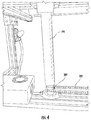
- Motor 201 is configured to turn flexible member 202 which in turn initiates vertical movement in actuator 204 ( see Fig. 4 ).
- the configuration in Figs. 1 and 2 includes two flexible members 202 and two actuators 204; however, any number of flexible members 202 and actuators 204 may be used (including only one of each).
- the motor 201 may be located immediately adjacent to the actuator 204 to eliminate the need for flexible member 202 (e.g., a gear train may be utilized).
- Flexible member 202 may be a belt, a chain, a rope, or any flexible object for translating motion from the motor 201 to the actuator 204.
- Fig. 4 shows a sprocket 203 at the interface between flexible member 202 and actuator 204. However, sprocket 203 may not be necessary (e.g., when flexible member 202 is a belt).
- the movement of actuator 204 relocates movable planar assembly in the vertical direction where (as described above) the movable planar assembly comprises right edge member 116, right partial member 116a, left edge member 117, left partial member 117a, intermediate horizontal member 122, and rear horizontal member 123.
- the movable planar assembly moves as sliding fittings 148, 149, 150, and 151 move along the surface of rear right member 112, rear left member 113, front right member 114, and front left member 115, respectively.
- the second mechanism is configured to rotate the moveable table assembly 400 about a horizontal axis.
- Motor 221 is configured to turn a flexible member 222, which in turn initiates vertical movement in an actuator 224 ( see Fig. 2 ).
- the configuration in Fig. 2 includes two flexible members 222 and two actuators 224; however, any number of flexible members 222 and actuators 224 may be used (including only one of each).
- the motor 221 may be located immediately adjacent to the actuator 224 to eliminate the need for flexible member 222 (e.g., a gear train may be utilized).
- Flexible member 222 may be a belt, a chain, a rope, or any flexible object for translating motion from the motor 221 to the actuator 224.
- motor 221 and actuators 224 are attached to beam 144, which includes three pivoting fittings 145, 146, and 147. Although three fittings are illustrated, any number of pivoting fittings may be used (including less than three or more than three).
- the three pivoting fittings 145, 146, and 147 are fastened to table frame 133 (in particular, to rear frame portion 133a).
- Each of the actuators 224 are attached to an anchor plate 225 such that beam 144 moves in a vertical direction due to motion of actuators 224. Because sliding brackets 140 and 141 can slide along rear right member 112 and rear left member 113, respectively, the movement of actuator 224 causes the rear section of the table assembly 400 to move in a vertical direction.
- sliding brackets 140 and 141 slide up along rear right member 112 and rear left member 113 (respectively) and sliding brackets 142 and 143 slide rearward (away from a user) along right edge member 116 and left edge member 117 (respectively) such that the table assembly 400 rotates to a steeper, more vertical position.
- the adaptive manufacturing table 100 may include a control panel 180.
- the control panel 180 may be located on the adaptive manufacturing table 100 (as shown in Fig. 1 ) or may be located remotely.
- the moveable table assembly 400 may be configured to provide a range of positions between a first position where table surface 130 is disposed in an approximately horizontal position and a second position where the table surface 130 is disposed approximately 70 degrees from horizontal.
- the moveable table assembly 400 may be moved in the vertical direction.
- the combination of angle and height adjustments may be designed to accommodate a comprehensive range of potential users (e.g., a range from a 5 th percentile female to a 95 th percentile male).
- the ability to change the position of the table (which can occur during manufacturing tasks because the projector does not require repositioning due to its static mounting to the moveable table assembly 400) has ergonomic benefits.
- a user may periodically reposition the moveable table assembly 400 to reduce fatigue.
- the adaptive manufacturing table 100 may include an automatic cable tie device 170.
- an automatic cable tie device 170 may include a control box 175, a gun 171, a cord 172, a reel 173, and a mounting arm 174.
- the automatic cable tie device 170 may be operated via an electric mechanism, a pneumatic mechanism, or any other suitable mechanism.
- a user may utilize the automatic cable tie device 170 to increase efficiency and reduce the time needed for manufacturing tasks.
- the control box 175 may be located on the shelf surface 127.
Landscapes
- Engineering & Computer Science (AREA)
- Manufacturing & Machinery (AREA)
- Mechanical Engineering (AREA)
- Microelectronics & Electronic Packaging (AREA)
- Physics & Mathematics (AREA)
- General Physics & Mathematics (AREA)
- Projection Apparatus (AREA)
- Transforming Electric Information Into Light Information (AREA)
Description
- This application is related to and claims priority benefits from
U.S. Provisional Application Serial No. 61/857,309 - The field of the invention relates to fixtures and processes for assembling and manufacturing wire harnesses.
- Many vehicles such as passenger aircraft, automobiles, buses, trains and the like require significant amounts of wiring for subsystems and components. For example, many modern vehicles utilize an increased number of integral electronic components due to safety and entertainment systems and an associated plurality of configurations based on customer requirements. Accordingly, manufacturing processes for these vehicles and their subcomponents and systems require an increasing number of wire harnesses and wire harness configurations. In many instances, a manufacturer may have hundreds of wire harness configurations such that each configuration includes an individualized drawing to be used during the assembly/manufacturing process. Traditionally, such drawings were hand drawn (i.e., hard copies) such as ink on mylar. However, many industries are implementing "paperless" initiatives that rely on digital Computer Aided Design (CAD) drawings for various reasons (i.e., ease of communication and collaboration over distance, consistency, repeatability, storage space and associated costs). However, certain assembly/manufacturing tasks (such as building wire harnesses) still require an interface with a representation of drawing data at a known scale. Constructing wire harnesses is often completed at a large table with pegs attached to the surface of the table for assisting in arranging the relevant wiring with a paper copy of the associated drawing (whether ink on mylar or a printed copy of a digital drawing). It is possible to build individualized tables for each harness configuration; however, the number of permutations of harness configurations may often be prohibitive.
- As an example,
U.S. Patent No. 8,066,383 describes a wire harness projection system including two separate elements, namely, arack 20 and a work bench 22, which are physically isolated from one another to reduce vibrations transmitted from work bench 22 to projector 16 (which is attached to rack 20). Projector 16 is configured to project an image I via mirror 18 onto work bench 22. Because the projector 16 is mounted independently from work bench 22, there is an intricate calibration process that must be repeated each time work bench 22 moves relative torack 20. - In certain situations, it may be desirable to project an image of a digital drawing onto the surface of a table assembly to facilitate manufacturing tasks using a projector that is rigidly mounted to the table assembly so as to avoid unnecessary calibration procedures.
- The terms "invention," "the invention," "this invention" and "the present invention" used in this patent are intended to refer broadly to all of the subject matter of this patent and the patent claims below. Statements containing these terms should be understood not to limit the subject matter described herein or to limit the meaning or scope of the patent claims below. Embodiments of the invention covered by this patent are defined by the claims below, not this summary. This summary is a high-level overview of various aspects of the invention and introduces some of the concepts that are further described in the Detailed Description section below. This summary is not intended to identify key or essential features of the claimed subject matter, nor is it intended to be used in isolation to determine the scope of the claimed subject matter. The subject matter should be understood by reference to appropriate portions of the entire specification of this patent, any or all drawings and each claim.
- According to the invention, an adaptive manufacturing table is provided as defined in claim 1. Further developments of the invention are the subject of the dependent claims. The projector, in some embodiments, is configured to directly project an image onto the table surface.
- In some embodiments, the adaptive manufacturing table further comprises one or more mechanisms for moving the table assembly. The one or more mechanisms for moving the table assembly, in certain embodiments, comprise a motor and a chain drive mechanism.
- The moveable table assembly of the adaptive manufacturing table, in certain embodiments, is configured to rotate and to translate. In some embodiments, the moveable table assembly is configured to rotate about a horizontal axis and to translate in a vertical direction. The moveable table assembly, in certain embodiments, is configured to rotate between a flat position at approximately 0 degrees to approximately 70 degrees. The adaptive manufacturing table, in some embodiments, further comprises a movable planar assembly disposed under the moveable table assembly wherein the movable planar assembly is configured to translate in a vertical direction.
- In some embodiments, the projector is a short throw projector.
- The adaptive manufacturing table, in some embodiments, further comprises an automatic cable tie device.
- The table surface of the adaptive manufacturing table, in certain embodiments, further comprises a plurality of holes.
- In some embodiments, the projector is secured by a projector frame portion. The projector frame portion, in certain embodiments, is attached to the structural frame assembly using one or more hinges such that the projector frame portion is configured to rotate.
- In certain embodiments of the present invention, the adaptive manufacturing table further comprises a shelf assembly.
- According to certain embodiments of the present invention, an adaptive manufacturing table comprises a moveable table assembly and a projector mounted to a projector frame. The moveable table assembly may comprise a table surface, a table frame disposed adjacent to the table surface, and a lower working surface disposed on a forward side of the table surface. Further, the moveable table assembly may rigidly interface with the projector frame.
- In some embodiments, the projector is configured to directly project an image onto the table surface.
- In certain embodiments, the moveable table assembly is configured to rotate and to translate.
- According to certain embodiments of the present invention, an adaptive manufacturing table comprises a moveable table assembly comprising a table surface comprising a plurality of holes and a projector such that the projector is rigidly mounted to the moveable table assembly.
- In some embodiments, the projector is configured to directly project an image onto the table surface.
- In certain embodiments, the moveable table assembly is configured to rotate and to translate.
-
-
Fig. 1 is a front right perspective view of an adaptive manufacturing table according to certain embodiments of the present invention. -
Fig. 2 is a rear left perspective view of the adaptive manufacturing table ofFig. 1 . -
Fig. 3 is a perspective view of a portion of a mechanism for changing the angle of the moveable table assembly of the adaptive manufacturing table ofFig. 1 . -
Fig. 4 is a perspective view of a portion of a mechanism for changing the vertical position of the moveable table assembly of the adaptive manufacturing table ofFig. 1 . -
Fig. 5 is a perspective view of a sliding fitting of the deployment apparatus of the adaptive manufacturing table ofFig. 1 . -
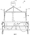
Fig. 6 is a front view of the adaptive manufacturing table ofFig. 1 . -
Fig. 7 is a side view of the adaptive manufacturing table ofFig. 1 with the projector frame portion in a rotated position. -
Fig. 8 is a rear left perspective view of the adaptive manufacturing table ofFig. 1 with the projector frame portion in a rotated position. - The subject matter of embodiments of the present invention is described here with specificity to meet statutory requirements, but this description is not necessarily intended to limit the scope of the claims. The claimed subject matter may be embodied in other ways, may include different elements or steps, and may be used in conjunction with other existing or future technologies. This description should not be interpreted as implying any particular order or arrangement among or between various steps or elements except when the order of individual steps or arrangement of elements is explicitly described.
-
Figs. 1-8 illustrate embodiments of an adaptive manufacturing table 100. In these embodiments, the adaptive manufacturing table 100 comprises astructural frame assembly 300, a moveable table assembly that includes atable surface 130, and aprojector 101 such that theprojector 101 is rigidly mounted to thestructural frame assembly 300. Thestructural frame assembly 300 may include a plurality of structural members configured to movetable surface 130 in one or more directions. - As shown in
Figs. 1 and2 , in some embodiments, thestructural frame assembly 300 includes four vertical corner members including rearright member 112, rearleft member 113, frontright member 114, and frontleft member 115. The corner members interface with a movable planar assembly that includesright edge member 116, right partial member 116a, leftedge member 117, left partial member 117a, intermediatehorizontal member 122, and rearhorizontal member 123. The movable planar assembly interfaces with rearright member 112 through sliding fitting 148, interfaces with rearleft member 113 through sliding fitting 149, interfaces with frontright member 114 through sliding fitting 150, and interfaces with frontleft member 115 through sliding fitting 151. - The movable planar assembly secures the front section of the table assembly (adjacent to a user) using sliding
brackets bracket 142 is slidably attached to the upper surface ofright edge member 116 and slidingbracket 143 is slidably attached to the upper surface ofleft edge member 117. Slidingbracket 142 is pivotally attached to the table assembly (described in more detail below) at the intersection offront frame portion 133c andright frame portion 133d. Slidingbracket 143 is pivotally attached to the table assembly at the intersection ofleft frame portion 133b andfront frame portion 133c. The rear section of the table assembly is attached to rearright member 112 and rearleft member 113 using slidingbrackets 140 and 141, respectively. Slidingbracket 140 is configured to slide along the length of rearright member 112 while sliding bracket 141 is configured to slide along the length of rearleft member 113. Moreover, slidingbracket 140 is pivotally attached to the table assembly at the intersection of rear frame portion 133a andright frame portion 133d. Sliding bracket 141 is pivotally attached to the table assembly at the intersection of rear frame portion 133a and leftframe portion 133b. - To provide lateral support, the
structural frame assembly 300 may includehorizontal support member 124, which is disposed approximately halfway between the rear vertical supports (rearright member 112 and rear left member 113) and the front vertical supports (frontright member 114 and front left member 115). The right hand end ofhorizontal support member 124 is attached to middleside support member 118. The left hand end ofhorizontal support member 124 is attached to middleside support member 119. At approximately the center ofhorizontal support member 124, verticalpartial support member 125 is attached and extends downward. - The lower end of vertical
partial support member 125 is attached to lowerhorizontal support member 126. Lowerhorizontal support member 126 is disposed approximately halfway between the rear vertical supports (rearright member 112 and rear left member 113) and the front vertical supports (frontright member 114 and front left member 115). The right hand end of lowerhorizontal support member 126 is attached to lower rightside support member 120. The left hand end of lowerhorizontal support member 126 is attached to lower leftside support member 121. - Lower
horizontal support member 126, lower rightside support member 120, and lower leftside support member 121 along with lowerrear support member 128 form a shelf assembly to support one or more shelf surfaces 127. - The
structural frame assembly 300 may include one or more casters/wheels 190. As shown inFig. 1 , in some embodiments, thestructural frame assembly 300 includes fourwheels 190 located at each of the lower four corners where the lower four corners are: the intersection of rearright member 112, lower rightside support member 120, and lowerrear support member 128; the intersection of rearleft member 113, lower leftside support member 121, and lowerrear support member 128; the intersection of frontright member 114 and lower rightside support member 120; and the intersection of frontleft member 115 and lower leftside support member 121. Although fourwheels 190 are shown in the lower corners as described above, any number of wheels 190 (including more than four and less than four) may be located anywhere to ensure mobility of the adaptive manufacturing table 100 (e.g., anywhere on lower rightside support member 120, lower leftside support member 121, or lower rear support member 128). In some embodiments, one or more of thewheels 190 may be locked. - The components of the
structural frame assembly 300 may be formed of materials including, but not limited to, a steel, aluminum, stainless steel, other metallic materials, composite materials, plastic, thermoplastic, or other similar materials. Moreover, the components of thestructural frame assembly 300 may be attached to one another via suitable fasteners, which include, but are not limited to, screws, bolts, rivets or other mechanical or chemical fasteners. - The
moveable table assembly 400 may include atable surface 130,table frame 133, and alower working surface 131. Thetable frame 133 may include rear frame portion 133a, leftframe portion 133b,front frame portion 133c, andright frame portion 133d. In some embodiments, thetable frame 133 may further include a plurality ofcorner gusset plates 132, which may be configured to provide rigidity totable frame 133. As described above and as illustrated inFigs. 1 and2 , the front section of thetable assembly 400 is configured to slide forward/aft alongright edge member 116 and leftedge member 117 using slidingbrackets table assembly 400 is configured to slide up/down along rearright member 112 and rearleft member 113 using slidingbrackets 140 and 141, respectively. - The rear section of the
table assembly 400 also interfaces withprojector frame portion 110, which securesprojector 101. As shown inFigs. 1 and2 , in some embodiments,projector frame portion 110 includes five structural members and attaches at three locations to rear frame portion 133a. These three attachment locations may include static mounts or, as illustrated inFigs. 7 and8 , the three mounts may include coaxial hinges such that theprojector frame portion 110 is configured to rotate rearward. Such a rotation facilitates access to the projector for various tasks such as service, maintenance, removal, etc. - Because the
projector 101 is mounted directly to themoveable table assembly 400 and moves with thetable assembly 400, theprojector 101 does not need to be adjusted or calibrated based on relocation or adjustment of themoveable table assembly 400. Theprojector 101 may be configured to directly project an image onto thetable surface 130. In some embodiments, theprojector 101 is a short throw projector. Theprojector 101 may be disposed in close proximity to thetable surface 130 such that a high resolution image may be produced over a large portion of the table (in some embodiments, approximately 100% of the surface area of table surface 130). - In certain embodiments, the projector uses a wireless signal (e.g., WIFI) to interface with a network for accessing files and transmitting input signals from the adaptive manufacturing table 100.
- As shown in
Fig. 5 ,table surface 130 may include a plurality ofholes 135. In some embodiments, holes 135 are ¼" diameter holes that are perpendicular totable surface 130 and are disposed in a one square inch grid pattern. In some embodiments, thetable surface 130 is approximately 37.5 inches x 74.5 inches. In certain embodiments,table surface 130 includes approximately 26,000holes 135, but may include as few as 1000 holes, and as many as 100,000 holes. Drop-in pegs may be inserted into theholes 135 where the pegs are configured for facilitating various arrangements on thetable surface 130. - The
lower working surface 131 is disposed adjacent to a user to provide a flat surface without holes. In some embodiments, thelower working surface 131 is disposed to correspond to a portion of the projected image fromprojector 101. For example,projector 101 may project interactive (or non-interactive) images such as toolbars, graphical icons, dialog boxes, data entry windows, or any other image (e.g., as part of a graphical user interface or GUI). The smooth surface of lower workingsurface 131 facilitates visualization of detailed images projected fromprojector 101. Similarly, aroll unit 134 includes material that can be unrolled, extended alongtable surface 130 and attached to the table surface 130 (e.g., using a hole 135). Thus, a user may deployroll unit 134 to view detailed images on thetable surface 130. - The
moveable table assembly 400 may include an input device configured to facilitate interaction with the images projected by projector 101 (i.e., for providing input commands). One example of an input device, as illustrated inFig. 1 ispen 136. In some embodiments, an input device may not be necessary as input commands may be detected in other ways, such as motion detection of a user's hand. - The components of the
moveable table assembly 400 may be formed of materials including, but not limited to, a steel, aluminum, stainless steel, other metallic materials, composite materials, plastic, thermoplastic, or other similar materials. In some embodiments,table surface 130 comprises Lexan. Moreover, the components of themoveable table assembly 400 may be attached to one another via suitable fasteners, which include, but are not limited to, screws, bolts, rivets or other mechanical or chemical fasteners. - The adaptive manufacturing table 100 may include one or more mechanisms for repositioning the
moveable table assembly 400. The one or more mechanisms for moving thetable assembly 400 may utilize any suitable device such as electrical motors or actuators, manual operation, pneumatic actuators, hydraulic actuators, or any other suitable device. - As shown in
Figs. 1-4 , in some embodiments, the adaptive manufacturing table 100 may include two mechanisms for moving thetable assembly 400. The first mechanism is configured to move movable planar assembly in the vertical direction.Motor 201 is configured to turnflexible member 202 which in turn initiates vertical movement in actuator 204 (seeFig. 4 ). The configuration inFigs. 1 and2 includes twoflexible members 202 and twoactuators 204; however, any number offlexible members 202 andactuators 204 may be used (including only one of each). In addition, in some embodiments, themotor 201 may be located immediately adjacent to theactuator 204 to eliminate the need for flexible member 202 (e.g., a gear train may be utilized).Flexible member 202 may be a belt, a chain, a rope, or any flexible object for translating motion from themotor 201 to theactuator 204.Fig. 4 shows asprocket 203 at the interface betweenflexible member 202 andactuator 204. However,sprocket 203 may not be necessary (e.g., whenflexible member 202 is a belt). - The movement of
actuator 204 relocates movable planar assembly in the vertical direction where (as described above) the movable planar assembly comprisesright edge member 116, right partial member 116a, leftedge member 117, left partial member 117a, intermediatehorizontal member 122, and rearhorizontal member 123. The movable planar assembly moves as slidingfittings right member 112, rearleft member 113, frontright member 114, and frontleft member 115, respectively. Because slidingbrackets 140 and 141 can slide along rearright member 112 and rearleft member 113, respectively, the movement ofactuator 204 causes the entiremoveable table assembly 400 to move in translation in the vertical direction (i.e., the angle oftable surface 130 remains constant during movement of actuator 204). - The second mechanism is configured to rotate the
moveable table assembly 400 about a horizontal axis.Motor 221 is configured to turn aflexible member 222, which in turn initiates vertical movement in an actuator 224 (seeFig. 2 ). The configuration inFig. 2 includes twoflexible members 222 and twoactuators 224; however, any number offlexible members 222 andactuators 224 may be used (including only one of each). In addition, in some embodiments, themotor 221 may be located immediately adjacent to theactuator 224 to eliminate the need for flexible member 222 (e.g., a gear train may be utilized).Flexible member 222 may be a belt, a chain, a rope, or any flexible object for translating motion from themotor 221 to theactuator 224. - As shown in
Fig. 2 ,motor 221 andactuators 224 are attached tobeam 144, which includes three pivotingfittings fittings actuators 224 are attached to ananchor plate 225 such thatbeam 144 moves in a vertical direction due to motion ofactuators 224. Because slidingbrackets 140 and 141 can slide along rearright member 112 and rearleft member 113, respectively, the movement ofactuator 224 causes the rear section of thetable assembly 400 to move in a vertical direction. To allow rotation of the table assembly, whenbeam 144 moves in a vertical direction, the front section of the table assembly is allowed to move in the forward/rear direction alongright edge member 116 and leftedge member 117 using slidingbrackets beam 144 moves down, slidingbrackets 140 and 141 slide down along rearright member 112 and rear left member 113 (respectively) and slidingbrackets right edge member 116 and left edge member 117 (respectively) such that thetable assembly 400 rotates to a flatter, more horizontal position. Conversely, whenbeam 144 moves up, slidingbrackets 140 and 141 slide up along rearright member 112 and rear left member 113 (respectively) and slidingbrackets right edge member 116 and left edge member 117 (respectively) such that thetable assembly 400 rotates to a steeper, more vertical position. - In some embodiments, as shown in
Fig. 1 , the adaptive manufacturing table 100 may include acontrol panel 180. Thecontrol panel 180 may be located on the adaptive manufacturing table 100 (as shown inFig. 1 ) or may be located remotely. - In some embodiments, the
moveable table assembly 400 may be configured to provide a range of positions between a first position wheretable surface 130 is disposed in an approximately horizontal position and a second position where thetable surface 130 is disposed approximately 70 degrees from horizontal. In addition to changing the angle of table surface 130 (with respect to horizontal), as described above, themoveable table assembly 400 may be moved in the vertical direction. The combination of angle and height adjustments may be designed to accommodate a comprehensive range of potential users (e.g., a range from a 5th percentile female to a 95th percentile male). Moreover, the ability to change the position of the table (which can occur during manufacturing tasks because the projector does not require repositioning due to its static mounting to the moveable table assembly 400) has ergonomic benefits. In addition to repositioning themoveable table assembly 400 to ensure a proper working height, a user may periodically reposition themoveable table assembly 400 to reduce fatigue. - The adaptive manufacturing table 100 may include an automatic cable tie device 170. As shown in
Figs. 1 and2 , an automatic cable tie device 170 may include acontrol box 175, agun 171, acord 172, areel 173, and a mountingarm 174. The automatic cable tie device 170 may be operated via an electric mechanism, a pneumatic mechanism, or any other suitable mechanism. A user may utilize the automatic cable tie device 170 to increase efficiency and reduce the time needed for manufacturing tasks. In some embodiments, as shown inFig. 1 , thecontrol box 175 may be located on theshelf surface 127. - Different arrangements of the components depicted in the drawings or described above, as well as components and steps not shown or described are possible. Similarly, some features and sub-combinations are useful and may be employed without reference to other features and sub-combinations. Embodiments of the invention have been described for illustrative and not restrictive purposes, and alternative embodiments will become apparent to readers of this patent. Accordingly, the present invention is not limited to the embodiments described above or depicted in the drawings, and various embodiments and modifications may be made without departing from the scope of the claims below.
Claims (15)
- An adaptive manufacturing table (100) for assembling and manufacturing wire harnesses, comprising:a structural frame assembly (300);a moveable table assembly (400) comprising a table surface (130) mounted to the structural frame assembly (300); anda projector (101);characterised in that the projector (101) is rigidly mounted to the moveable table assembly (400) such that the projector (101) moves with the movement of the table assembly (400).
- The adaptive manufacturing table (100) of claim 1, wherein the projector (101) is secured by a projector frame portion (110).
- The adaptive manufacturing table (100) of claim 2, wherein the moveable table assembly (400) interfaces with the projector frame portion (110).
- The adaptive manufacturing table (100) of claim 3, wherein the projector frame portion (110) is attached to the moveable table assembly (400) using one or more hinges such that the projector frame portion (110) is configured to rotate.
- The adaptive manufacturing table (100) of any of the preceding claims, wherein the projector (101) is configured to directly project an image onto the table surface (130).
- The adaptive manufacturing table (100) of the preceding claims, further comprising one or more mechanisms for moving the table assembly (400).
- The adaptive manufacturing table (100) of claim 6, wherein the one or more mechanisms for moving the table assembly (400) comprise a motor (221) and a chain drive mechanism.
- The adaptive manufacturing table (100) of any of the preceding claims, wherein the moveable table assembly (400) is configured to rotate and to translate.
- The adaptive manufacturing table (100) of claim 8, wherein the moveable table assembly (400) is configured to rotate about a horizontal axis and to translate in a vertical direction.
- The adaptive manufacturing table (100) of claim 9, wherein the moveable table assembly (400) is configured to rotate between a flat position at approximately 0 degrees to approximately 70 degrees.
- The adaptive manufacturing table (100) of any of the preceding claims, further comprising a movable planar assembly disposed under the moveable table assembly (400) wherein the movable planar assembly is configured to translate in a vertical direction.
- The adaptive manufacturing table (100) of any of the preceding claims, wherein the projector (101) is a short throw projector.
- The adaptive manufacturing table (100) of any of the preceding claims, further comprising an automatic cable tie device (170).
- The adaptive manufacturing table (100) of any of the preceding claims, wherein the table surface (130) comprises a plurality of holes (135) for receiving drop-in pegs.
- The adaptive manufacturing table (100) of any of the preceding claims, further comprising a shelf assembly for supporting one or more shelf surfaces (127).
Applications Claiming Priority (2)
| Application Number | Priority Date | Filing Date | Title |
|---|---|---|---|
| US201361857309P | 2013-07-23 | 2013-07-23 | |
| PCT/US2014/047534 WO2015013232A1 (en) | 2013-07-23 | 2014-07-22 | Adaptive manufacturing table |
Publications (2)
| Publication Number | Publication Date |
|---|---|
| EP3024621A1 EP3024621A1 (en) | 2016-06-01 |
| EP3024621B1 true EP3024621B1 (en) | 2020-10-14 |
Family
ID=51300870
Family Applications (1)
| Application Number | Title | Priority Date | Filing Date |
|---|---|---|---|
| EP14750090.4A Active EP3024621B1 (en) | 2013-07-23 | 2014-07-22 | Adaptive manufacturing table |
Country Status (4)
| Country | Link |
|---|---|
| US (1) | US10832835B2 (en) |
| EP (1) | EP3024621B1 (en) |
| MX (1) | MX369367B (en) |
| WO (1) | WO2015013232A1 (en) |
Families Citing this family (11)
| Publication number | Priority date | Publication date | Assignee | Title |
|---|---|---|---|---|
| DE102016102799A1 (en) * | 2016-02-17 | 2017-08-17 | J. Michael Mehltretter | Carrier system for an ergonomically adjustable workplace |
| EP3363599B1 (en) * | 2017-02-17 | 2021-11-03 | J. Michael Mehltretter | Carrier system with shelf cart |
| EP3441194B1 (en) * | 2017-08-08 | 2022-04-06 | J. Michael Mehltretter | Ergonomically adjustable workstation that can be efficiently equipped comprising a support system |
| CN108747996A (en) * | 2018-06-14 | 2018-11-06 | 芜湖博康机电有限公司 | A kind of automotive wire bundle processing workbench |
| CN108772802A (en) * | 2018-06-14 | 2018-11-09 | 芜湖博康机电有限公司 | A kind of improved automotive harness processing workbench |
| CN109240033B (en) * | 2018-10-29 | 2020-08-14 | 黄河科技学院 | An image processing and display device |
| CN109719649A (en) * | 2019-02-20 | 2019-05-07 | 天津跃峰科技股份有限公司 | A kind of mobile frock clamp of work pieces process |
| US11866207B2 (en) * | 2019-10-30 | 2024-01-09 | Panduit Corp. | Flush mount tabletop for automatic cable tie tool |
| CN111243795B (en) * | 2020-01-20 | 2020-11-06 | 青岛成通源电子有限公司 | Adjustable automobile wire harness assembling table |
| US11160188B2 (en) * | 2020-02-26 | 2021-10-26 | Schweitzer Engineering Laboratories, Inc. | Control panel module assembly devices and techniques |
| CN113146171A (en) * | 2021-03-05 | 2021-07-23 | 南京晨光集团有限责任公司 | Satellite attitude conversion device with rotation azimuth lifting function |
Family Cites Families (14)
| Publication number | Priority date | Publication date | Assignee | Title |
|---|---|---|---|---|
| US2805471A (en) * | 1953-09-25 | 1957-09-10 | Ncr Co | Method for locating paths of wires on lacing board |
| US4359070A (en) * | 1980-11-03 | 1982-11-16 | Thomas & Betts Corporation | Bundling tie applying kit |
| US4979544A (en) | 1988-09-30 | 1990-12-25 | The Boeing Company | Universal wire harness form board assembly |
| DE9312020U1 (en) * | 1993-08-12 | 1993-10-28 | IHS Consulting GmbH, 58239 Schwerte | Mounting device for equipping and wiring equipment panels in switchgear engineering |
| US6019484A (en) * | 1998-07-27 | 2000-02-01 | Seyler; Christopher M. | Portable task lighting device |
| US6604829B2 (en) * | 1999-03-03 | 2003-08-12 | 3M Innovative Properties Company | Compact integrated front projection system |
| JP2003012285A (en) * | 2001-07-02 | 2003-01-15 | Misawa Homes Co Ltd | Workbench |
| DE10320557B4 (en) * | 2003-05-07 | 2006-04-13 | Martin Mechanic Friedrich Martin Gmbh & Co. Kg | Method and device for supporting activities to be carried out at a workshop workplace |
| KR20050007990A (en) * | 2003-07-12 | 2005-01-21 | 삼성전자주식회사 | Method for multplexing of user traffic in a mobile communication system |
| DE102004010176B4 (en) * | 2004-03-02 | 2011-05-05 | Fraunhofer-Gesellschaft zur Förderung der angewandten Forschung e.V. | Device and workstation for manufacturing a harness assembly |
| KR20050079909A (en) * | 2005-04-07 | 2005-08-11 | 최정섭 | Worktable for high and low adjustment possible |
| US8066383B2 (en) * | 2006-09-01 | 2011-11-29 | Siemens Industry, Inc. | Wire harness projection guidance system and method |
| WO2009120295A2 (en) * | 2008-03-24 | 2009-10-01 | Maclean Greg A | Digital wire harness assembly system |
| US8919966B2 (en) * | 2009-01-29 | 2014-12-30 | Speranza, Inc. | Rotatable mounting system for a projection system |
-
2014
- 2014-07-22 WO PCT/US2014/047534 patent/WO2015013232A1/en not_active Ceased
- 2014-07-22 EP EP14750090.4A patent/EP3024621B1/en active Active
- 2014-07-22 US US14/907,090 patent/US10832835B2/en active Active
- 2014-07-22 MX MX2016000850A patent/MX369367B/en active IP Right Grant
Non-Patent Citations (1)
| Title |
|---|
| None * |
Also Published As
| Publication number | Publication date |
|---|---|
| MX2016000850A (en) | 2016-04-27 |
| US10832835B2 (en) | 2020-11-10 |
| US20160155544A1 (en) | 2016-06-02 |
| EP3024621A1 (en) | 2016-06-01 |
| MX369367B (en) | 2019-11-06 |
| WO2015013232A1 (en) | 2015-01-29 |
Similar Documents
| Publication | Publication Date | Title |
|---|---|---|
| US10832835B2 (en) | Adaptive manufacturing table | |
| US10850852B2 (en) | Methods for arranging passenger seats and passenger service units in aircraft cabins | |
| DE102014019125B4 (en) | Motor vehicle with a control device and method for controlling a device depending on a seat inclination | |
| US10309153B2 (en) | Support system for rolled material | |
| RU2646722C2 (en) | Autonomous vehicle with folding seats | |
| EP3291659B1 (en) | Slide rail assembly applied to a rack system for mounting an object to a rack | |
| JP6040304B2 (en) | Expandable in-flight entertainment monitor | |
| EP3647111B1 (en) | Dynamic electro-mechanical ottoman | |
| DE102014212881B4 (en) | Center bracing arrangement for a vehicle interior | |
| US8733028B2 (en) | Display transformation assembly for a visualization system | |
| CN103708035A (en) | Assembly for aircraft cockpit, aircraft cockpit equipped with such assembly and aircraft | |
| CN102246609B (en) | Aircraft cockpit with information display device | |
| CN203929657U (en) | Circuit board double-side detection equipment | |
| US20190031353A1 (en) | Convertible seat with leg rest or without leg rest and conversion method | |
| CN202660177U (en) | Folding displayer control table | |
| CN106181909B (en) | Multi-axis bearing device with adjustable angle | |
| CN115196019A (en) | Tray table device for a console element, console element and seat unit | |
| US8696089B2 (en) | Portable printer for direct imaging on surfaces | |
| US8721464B2 (en) | Biaxial suspension type dynamic simulator | |
| KR20120019684A (en) | Cable support device of winch for transfer system using cable | |
| JPH04298370A (en) | User interface terminal of plurality of mode printer | |
| EP3168049B1 (en) | Printing apparatus and method of moving medium support unit | |
| KR20180064332A (en) | 3-dimensional printer where injecting direction of modeling material is able to be variable | |
| EP3463915B1 (en) | Printer band edge hold down systems | |
| CN105021612A (en) | Double-sided detection equipment for circuit board |
Legal Events
| Date | Code | Title | Description |
|---|---|---|---|
| PUAI | Public reference made under article 153(3) epc to a published international application that has entered the european phase |
Free format text: ORIGINAL CODE: 0009012 |
|
| 17P | Request for examination filed |
Effective date: 20160223 |
|
| AK | Designated contracting states |
Kind code of ref document: A1 Designated state(s): AL AT BE BG CH CY CZ DE DK EE ES FI FR GB GR HR HU IE IS IT LI LT LU LV MC MK MT NL NO PL PT RO RS SE SI SK SM TR |
|
| AX | Request for extension of the european patent |
Extension state: BA ME |
|
| DAX | Request for extension of the european patent (deleted) | ||
| STAA | Information on the status of an ep patent application or granted ep patent |
Free format text: STATUS: EXAMINATION IS IN PROGRESS |
|
| 17Q | First examination report despatched |
Effective date: 20181017 |
|
| RAP1 | Party data changed (applicant data changed or rights of an application transferred) |
Owner name: SAFRAN SEATS USA LLC |
|
| REG | Reference to a national code |
Ref country code: DE Ref legal event code: R079 Ref document number: 602014071219 Country of ref document: DE Free format text: PREVIOUS MAIN CLASS: B25H0001140000 Ipc: H01B0013012000 |
|
| GRAP | Despatch of communication of intention to grant a patent |
Free format text: ORIGINAL CODE: EPIDOSNIGR1 |
|
| STAA | Information on the status of an ep patent application or granted ep patent |
Free format text: STATUS: GRANT OF PATENT IS INTENDED |
|
| RIC1 | Information provided on ipc code assigned before grant |
Ipc: H05K 13/00 20060101ALI20200430BHEP Ipc: H01B 13/012 20060101AFI20200430BHEP Ipc: B25H 1/18 20060101ALI20200430BHEP Ipc: B25H 1/16 20060101ALI20200430BHEP |
|
| INTG | Intention to grant announced |
Effective date: 20200519 |
|
| GRAS | Grant fee paid |
Free format text: ORIGINAL CODE: EPIDOSNIGR3 |
|
| GRAA | (expected) grant |
Free format text: ORIGINAL CODE: 0009210 |
|
| STAA | Information on the status of an ep patent application or granted ep patent |
Free format text: STATUS: THE PATENT HAS BEEN GRANTED |
|
| AK | Designated contracting states |
Kind code of ref document: B1 Designated state(s): AL AT BE BG CH CY CZ DE DK EE ES FI FR GB GR HR HU IE IS IT LI LT LU LV MC MK MT NL NO PL PT RO RS SE SI SK SM TR |
|
| REG | Reference to a national code |
Ref country code: GB Ref legal event code: FG4D |
|
| REG | Reference to a national code |
Ref country code: AT Ref legal event code: REF Ref document number: 1324379 Country of ref document: AT Kind code of ref document: T Effective date: 20201015 Ref country code: CH Ref legal event code: EP |
|
| REG | Reference to a national code |
Ref country code: DE Ref legal event code: R096 Ref document number: 602014071219 Country of ref document: DE |
|
| REG | Reference to a national code |
Ref country code: IE Ref legal event code: FG4D |
|
| REG | Reference to a national code |
Ref country code: AT Ref legal event code: MK05 Ref document number: 1324379 Country of ref document: AT Kind code of ref document: T Effective date: 20201014 |
|
| REG | Reference to a national code |
Ref country code: NL Ref legal event code: MP Effective date: 20201014 |
|
| PG25 | Lapsed in a contracting state [announced via postgrant information from national office to epo] |
Ref country code: RS Free format text: LAPSE BECAUSE OF FAILURE TO SUBMIT A TRANSLATION OF THE DESCRIPTION OR TO PAY THE FEE WITHIN THE PRESCRIBED TIME-LIMIT Effective date: 20201014 Ref country code: FI Free format text: LAPSE BECAUSE OF FAILURE TO SUBMIT A TRANSLATION OF THE DESCRIPTION OR TO PAY THE FEE WITHIN THE PRESCRIBED TIME-LIMIT Effective date: 20201014 Ref country code: NL Free format text: LAPSE BECAUSE OF FAILURE TO SUBMIT A TRANSLATION OF THE DESCRIPTION OR TO PAY THE FEE WITHIN THE PRESCRIBED TIME-LIMIT Effective date: 20201014 Ref country code: PT Free format text: LAPSE BECAUSE OF FAILURE TO SUBMIT A TRANSLATION OF THE DESCRIPTION OR TO PAY THE FEE WITHIN THE PRESCRIBED TIME-LIMIT Effective date: 20210215 Ref country code: NO Free format text: LAPSE BECAUSE OF FAILURE TO SUBMIT A TRANSLATION OF THE DESCRIPTION OR TO PAY THE FEE WITHIN THE PRESCRIBED TIME-LIMIT Effective date: 20210114 Ref country code: GR Free format text: LAPSE BECAUSE OF FAILURE TO SUBMIT A TRANSLATION OF THE DESCRIPTION OR TO PAY THE FEE WITHIN THE PRESCRIBED TIME-LIMIT Effective date: 20210115 |
|
| REG | Reference to a national code |
Ref country code: LT Ref legal event code: MG4D |
|
| PG25 | Lapsed in a contracting state [announced via postgrant information from national office to epo] |
Ref country code: SE Free format text: LAPSE BECAUSE OF FAILURE TO SUBMIT A TRANSLATION OF THE DESCRIPTION OR TO PAY THE FEE WITHIN THE PRESCRIBED TIME-LIMIT Effective date: 20201014 Ref country code: LV Free format text: LAPSE BECAUSE OF FAILURE TO SUBMIT A TRANSLATION OF THE DESCRIPTION OR TO PAY THE FEE WITHIN THE PRESCRIBED TIME-LIMIT Effective date: 20201014 Ref country code: IS Free format text: LAPSE BECAUSE OF FAILURE TO SUBMIT A TRANSLATION OF THE DESCRIPTION OR TO PAY THE FEE WITHIN THE PRESCRIBED TIME-LIMIT Effective date: 20210214 Ref country code: PL Free format text: LAPSE BECAUSE OF FAILURE TO SUBMIT A TRANSLATION OF THE DESCRIPTION OR TO PAY THE FEE WITHIN THE PRESCRIBED TIME-LIMIT Effective date: 20201014 Ref country code: BG Free format text: LAPSE BECAUSE OF FAILURE TO SUBMIT A TRANSLATION OF THE DESCRIPTION OR TO PAY THE FEE WITHIN THE PRESCRIBED TIME-LIMIT Effective date: 20210114 Ref country code: ES Free format text: LAPSE BECAUSE OF FAILURE TO SUBMIT A TRANSLATION OF THE DESCRIPTION OR TO PAY THE FEE WITHIN THE PRESCRIBED TIME-LIMIT Effective date: 20201014 Ref country code: AT Free format text: LAPSE BECAUSE OF FAILURE TO SUBMIT A TRANSLATION OF THE DESCRIPTION OR TO PAY THE FEE WITHIN THE PRESCRIBED TIME-LIMIT Effective date: 20201014 |
|
| PG25 | Lapsed in a contracting state [announced via postgrant information from national office to epo] |
Ref country code: HR Free format text: LAPSE BECAUSE OF FAILURE TO SUBMIT A TRANSLATION OF THE DESCRIPTION OR TO PAY THE FEE WITHIN THE PRESCRIBED TIME-LIMIT Effective date: 20201014 |
|
| REG | Reference to a national code |
Ref country code: DE Ref legal event code: R097 Ref document number: 602014071219 Country of ref document: DE |
|
| PG25 | Lapsed in a contracting state [announced via postgrant information from national office to epo] |
Ref country code: SK Free format text: LAPSE BECAUSE OF FAILURE TO SUBMIT A TRANSLATION OF THE DESCRIPTION OR TO PAY THE FEE WITHIN THE PRESCRIBED TIME-LIMIT Effective date: 20201014 Ref country code: RO Free format text: LAPSE BECAUSE OF FAILURE TO SUBMIT A TRANSLATION OF THE DESCRIPTION OR TO PAY THE FEE WITHIN THE PRESCRIBED TIME-LIMIT Effective date: 20201014 Ref country code: LT Free format text: LAPSE BECAUSE OF FAILURE TO SUBMIT A TRANSLATION OF THE DESCRIPTION OR TO PAY THE FEE WITHIN THE PRESCRIBED TIME-LIMIT Effective date: 20201014 Ref country code: SM Free format text: LAPSE BECAUSE OF FAILURE TO SUBMIT A TRANSLATION OF THE DESCRIPTION OR TO PAY THE FEE WITHIN THE PRESCRIBED TIME-LIMIT Effective date: 20201014 Ref country code: CZ Free format text: LAPSE BECAUSE OF FAILURE TO SUBMIT A TRANSLATION OF THE DESCRIPTION OR TO PAY THE FEE WITHIN THE PRESCRIBED TIME-LIMIT Effective date: 20201014 Ref country code: EE Free format text: LAPSE BECAUSE OF FAILURE TO SUBMIT A TRANSLATION OF THE DESCRIPTION OR TO PAY THE FEE WITHIN THE PRESCRIBED TIME-LIMIT Effective date: 20201014 |
|
| PLBE | No opposition filed within time limit |
Free format text: ORIGINAL CODE: 0009261 |
|
| STAA | Information on the status of an ep patent application or granted ep patent |
Free format text: STATUS: NO OPPOSITION FILED WITHIN TIME LIMIT |
|
| PG25 | Lapsed in a contracting state [announced via postgrant information from national office to epo] |
Ref country code: DK Free format text: LAPSE BECAUSE OF FAILURE TO SUBMIT A TRANSLATION OF THE DESCRIPTION OR TO PAY THE FEE WITHIN THE PRESCRIBED TIME-LIMIT Effective date: 20201014 |
|
| 26N | No opposition filed |
Effective date: 20210715 |
|
| PG25 | Lapsed in a contracting state [announced via postgrant information from national office to epo] |
Ref country code: AL Free format text: LAPSE BECAUSE OF FAILURE TO SUBMIT A TRANSLATION OF THE DESCRIPTION OR TO PAY THE FEE WITHIN THE PRESCRIBED TIME-LIMIT Effective date: 20201014 Ref country code: IT Free format text: LAPSE BECAUSE OF FAILURE TO SUBMIT A TRANSLATION OF THE DESCRIPTION OR TO PAY THE FEE WITHIN THE PRESCRIBED TIME-LIMIT Effective date: 20201014 |
|
| PG25 | Lapsed in a contracting state [announced via postgrant information from national office to epo] |
Ref country code: SI Free format text: LAPSE BECAUSE OF FAILURE TO SUBMIT A TRANSLATION OF THE DESCRIPTION OR TO PAY THE FEE WITHIN THE PRESCRIBED TIME-LIMIT Effective date: 20201014 |
|
| REG | Reference to a national code |
Ref country code: CH Ref legal event code: PL |
|
| PG25 | Lapsed in a contracting state [announced via postgrant information from national office to epo] |
Ref country code: MC Free format text: LAPSE BECAUSE OF FAILURE TO SUBMIT A TRANSLATION OF THE DESCRIPTION OR TO PAY THE FEE WITHIN THE PRESCRIBED TIME-LIMIT Effective date: 20201014 |
|
| REG | Reference to a national code |
Ref country code: BE Ref legal event code: MM Effective date: 20210731 |
|
| PG25 | Lapsed in a contracting state [announced via postgrant information from national office to epo] |
Ref country code: LI Free format text: LAPSE BECAUSE OF NON-PAYMENT OF DUE FEES Effective date: 20210731 Ref country code: CH Free format text: LAPSE BECAUSE OF NON-PAYMENT OF DUE FEES Effective date: 20210731 |
|
| PG25 | Lapsed in a contracting state [announced via postgrant information from national office to epo] |
Ref country code: IS Free format text: LAPSE BECAUSE OF FAILURE TO SUBMIT A TRANSLATION OF THE DESCRIPTION OR TO PAY THE FEE WITHIN THE PRESCRIBED TIME-LIMIT Effective date: 20210214 Ref country code: LU Free format text: LAPSE BECAUSE OF NON-PAYMENT OF DUE FEES Effective date: 20210722 |
|
| PG25 | Lapsed in a contracting state [announced via postgrant information from national office to epo] |
Ref country code: IE Free format text: LAPSE BECAUSE OF NON-PAYMENT OF DUE FEES Effective date: 20210722 Ref country code: BE Free format text: LAPSE BECAUSE OF NON-PAYMENT OF DUE FEES Effective date: 20210731 |
|
| PG25 | Lapsed in a contracting state [announced via postgrant information from national office to epo] |
Ref country code: HU Free format text: LAPSE BECAUSE OF FAILURE TO SUBMIT A TRANSLATION OF THE DESCRIPTION OR TO PAY THE FEE WITHIN THE PRESCRIBED TIME-LIMIT; INVALID AB INITIO Effective date: 20140722 |
|
| PG25 | Lapsed in a contracting state [announced via postgrant information from national office to epo] |
Ref country code: CY Free format text: LAPSE BECAUSE OF FAILURE TO SUBMIT A TRANSLATION OF THE DESCRIPTION OR TO PAY THE FEE WITHIN THE PRESCRIBED TIME-LIMIT Effective date: 20201014 |
|
| PG25 | Lapsed in a contracting state [announced via postgrant information from national office to epo] |
Ref country code: MK Free format text: LAPSE BECAUSE OF FAILURE TO SUBMIT A TRANSLATION OF THE DESCRIPTION OR TO PAY THE FEE WITHIN THE PRESCRIBED TIME-LIMIT Effective date: 20201014 |
|
| PG25 | Lapsed in a contracting state [announced via postgrant information from national office to epo] |
Ref country code: MT Free format text: LAPSE BECAUSE OF FAILURE TO SUBMIT A TRANSLATION OF THE DESCRIPTION OR TO PAY THE FEE WITHIN THE PRESCRIBED TIME-LIMIT Effective date: 20201014 |
|
| PGFP | Annual fee paid to national office [announced via postgrant information from national office to epo] |
Ref country code: DE Payment date: 20250722 Year of fee payment: 12 |
|
| PGFP | Annual fee paid to national office [announced via postgrant information from national office to epo] |
Ref country code: GB Payment date: 20250724 Year of fee payment: 12 |
|
| PGFP | Annual fee paid to national office [announced via postgrant information from national office to epo] |
Ref country code: FR Payment date: 20250722 Year of fee payment: 12 |
|
| PG25 | Lapsed in a contracting state [announced via postgrant information from national office to epo] |
Ref country code: TR Free format text: LAPSE BECAUSE OF FAILURE TO SUBMIT A TRANSLATION OF THE DESCRIPTION OR TO PAY THE FEE WITHIN THE PRESCRIBED TIME-LIMIT Effective date: 20201014 |