EP3024395B1 - Non-imaging two dimensional array probe and system for classifying carotid stenosis - Google Patents
Non-imaging two dimensional array probe and system for classifying carotid stenosis Download PDFInfo
- Publication number
- EP3024395B1 EP3024395B1 EP14752663.6A EP14752663A EP3024395B1 EP 3024395 B1 EP3024395 B1 EP 3024395B1 EP 14752663 A EP14752663 A EP 14752663A EP 3024395 B1 EP3024395 B1 EP 3024395B1
- Authority
- EP
- European Patent Office
- Prior art keywords
- doppler
- imaging
- ultrasound system
- stenosis
- turbulence
- Prior art date
- Legal status (The legal status is an assumption and is not a legal conclusion. Google has not performed a legal analysis and makes no representation as to the accuracy of the status listed.)
- Active
Links
Images


Classifications
-
- A—HUMAN NECESSITIES
- A61—MEDICAL OR VETERINARY SCIENCE; HYGIENE
- A61B—DIAGNOSIS; SURGERY; IDENTIFICATION
- A61B8/00—Diagnosis using ultrasonic, sonic or infrasonic waves
- A61B8/06—Measuring blood flow
-
- A—HUMAN NECESSITIES
- A61—MEDICAL OR VETERINARY SCIENCE; HYGIENE
- A61B—DIAGNOSIS; SURGERY; IDENTIFICATION
- A61B8/00—Diagnosis using ultrasonic, sonic or infrasonic waves
- A61B8/08—Clinical applications
- A61B8/0891—Clinical applications for diagnosis of blood vessels
-
- A—HUMAN NECESSITIES
- A61—MEDICAL OR VETERINARY SCIENCE; HYGIENE
- A61B—DIAGNOSIS; SURGERY; IDENTIFICATION
- A61B8/00—Diagnosis using ultrasonic, sonic or infrasonic waves
- A61B8/44—Constructional features of the ultrasonic, sonic or infrasonic diagnostic device
- A61B8/4483—Constructional features of the ultrasonic, sonic or infrasonic diagnostic device characterised by features of the ultrasound transducer
-
- A—HUMAN NECESSITIES
- A61—MEDICAL OR VETERINARY SCIENCE; HYGIENE
- A61B—DIAGNOSIS; SURGERY; IDENTIFICATION
- A61B8/00—Diagnosis using ultrasonic, sonic or infrasonic waves
- A61B8/48—Diagnostic techniques
- A61B8/483—Diagnostic techniques involving the acquisition of a 3D volume of data
-
- A—HUMAN NECESSITIES
- A61—MEDICAL OR VETERINARY SCIENCE; HYGIENE
- A61B—DIAGNOSIS; SURGERY; IDENTIFICATION
- A61B8/00—Diagnosis using ultrasonic, sonic or infrasonic waves
- A61B8/48—Diagnostic techniques
- A61B8/488—Diagnostic techniques involving Doppler signals
-
- A—HUMAN NECESSITIES
- A61—MEDICAL OR VETERINARY SCIENCE; HYGIENE
- A61B—DIAGNOSIS; SURGERY; IDENTIFICATION
- A61B8/00—Diagnosis using ultrasonic, sonic or infrasonic waves
- A61B8/52—Devices using data or image processing specially adapted for diagnosis using ultrasonic, sonic or infrasonic waves
- A61B8/5215—Devices using data or image processing specially adapted for diagnosis using ultrasonic, sonic or infrasonic waves involving processing of medical diagnostic data
- A61B8/5223—Devices using data or image processing specially adapted for diagnosis using ultrasonic, sonic or infrasonic waves involving processing of medical diagnostic data for extracting a diagnostic or physiological parameter from medical diagnostic data
-
- G—PHYSICS
- G16—INFORMATION AND COMMUNICATION TECHNOLOGY [ICT] SPECIALLY ADAPTED FOR SPECIFIC APPLICATION FIELDS
- G16H—HEALTHCARE INFORMATICS, i.e. INFORMATION AND COMMUNICATION TECHNOLOGY [ICT] SPECIALLY ADAPTED FOR THE HANDLING OR PROCESSING OF MEDICAL OR HEALTHCARE DATA
- G16H50/00—ICT specially adapted for medical diagnosis, medical simulation or medical data mining; ICT specially adapted for detecting, monitoring or modelling epidemics or pandemics
- G16H50/30—ICT specially adapted for medical diagnosis, medical simulation or medical data mining; ICT specially adapted for detecting, monitoring or modelling epidemics or pandemics for calculating health indices; for individual health risk assessment
Definitions
- This invention relates to medical diagnostic ultrasound systems and, in particular, to a non-imaging Doppler probe system for automated screening of carotid stenosis.
- Stroke is the third leading cause of death worldwide. According to the World Health Organization, stroke accounted for more than 5.5 million deaths in 2002 with about 50% of those deaths occurring in China and India. Although the incidence is declining in developed countries, stroke nevertheless accounts for a mortality of 163,000 in the United States. A significant portion of these deaths are believed to be a result of disease in the carotid bifurcation.
- the carotid artery bifurcation where the common carotid artery (CCA) branches into the internal (ICA) and external (ECA) carotid arteries, is a common site of atherosclerotic disease. Stenosis or narrowing of the ICA, the branch which supplies blood to the brain, has long been known to be related to the incidence of ischemic stroke. The use of the severity of carotid stenosis has evolved as a surrogate measure of the risk of stroke.
- carotid atherosclerosis and mortality associated with stroke is an increasing problem in the developing world.
- a carotid artery screening device that can be used in low resource settings would address this growing problem by offering several features.
- a non-imaging Doppler ultrasound system according to the preamble of independent claim 1 is known from WO02/069805 .
- a diagnostic ultrasound system for carotid artery diagnosis includes a simple, non-imaging Doppler ultrasound probe.
- the probe has a two dimensional array of transducer elements with a low count of elements of relatively large size which can cover an area of the carotid artery at its bifurcation.
- the large sized elements are operated independently with no phasing, thereby reducing the cost of the Doppler system.
- the probe and system of the present invention can produce a representation of carotid blood flow in two or three dimensions and can assemble an extended view of the flow by matching segments of the carotid flow as the probe is moved over the vessel.
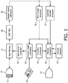
- An ultrasound system constructed in accordance with the principles of the present invention is shown in block diagram form.
- An ultrasound probe 10 contains a transducer array 12 of transducer elements which transmit ultrasound waves into the body and receive returning echo signals for Doppler processing. Control and timing of ultrasound transmission and reception is provided by a beamformer controller 16 which controls system beamformer 14.
- the beamformer 14 is not a conventional delay-and-sum beamformer as the transducer array is not operated in a phased manner. Instead, each element is separately actuated to transmit ultrasound waves directly into the body from its front surface and receive reflections from the waves individually.
- the beamformer controls the timing of successive transmit-receive intervals (the pulse repetition interval or PRI) by each transducer so that an ensemble of temporally spaced echoes is received by each transducer element at successive depths over a depth range of interest, which is the nominal depth at which the carotid artery is located.
- Each ensemble of echo samples can then be Doppler-process to detect the flow condition in front of every transducer element.
- a quadrature bandpass filter 18 processes the echo signals into quadrature I and Q components. The separate components are used by a Doppler angle estimator 20 to estimate the phase or frequency shift of a Doppler signal at the depths in front of each transducer element where Doppler interrogation is to be performed. Alternatively Doppler power may be estimated.
- the Doppler frequencies or intensities at depths in front of each transducer which are produced by the Doppler angle estimator 20 can be mapped directly to velocity values of flow or Doppler power at those depth locations.
- This Doppler data is coupled to a flow image processor 30 which spatially processes the data into a two or three dimensional image format, in which the velocity values are color- or intensity-coded.
- This spatial Doppler vessel map is processed by a display processor 36 and displayed on display 52 to illustrate the locations in the anatomy beneath the array transducer where flow is taking place and the velocity and direction of that flow by the color coding or Doppler power by intensity modulation.
- Doppler data is also coupled to a spectral Doppler processor 32 which produces a spectral analysis of the Doppler data for peak systolic velocity and turbulence analysis as described below.
- a Doppler angle processor 40 conditions the process for the angle of Doppler interrogation which is set by inclining the direction of wave transmission by the transducer elements as described below.
- a graphics processor 34 is provided to overlay vessel map coordinates and other graphical data such as patient name on the displayed image.
- a volume renderer 24 performs volume rendering of three dimensional vessel map data for the production of three dimensional vessel maps as described below. The entire system is operated by user controls 50.
- FIGURE 2 illustrates a transducer array 12 for a probe 10 of the present invention.
- This embodiment is an array for a probe with a total of 80 elements, each measuring 3 mm by 3 mm arranged in a two dimensional matrix containing 10 rows by 8 columns. In such a configuration, the area of coverage is 30 mm by 24 mm.
- Transducer arrays with this small number of elements and elements of this relatively large individual size are easier to dice than fine-pitched array elements, making this array simple to fabricate with high yields and hence relatively inexpensive to make.
- the factors to consider in selecting the number of element include coverage, resolution, and a number which provides acceptable accuracy as compared to a standard ultrasound probe.
- Element sizes ranging from 3mm by 3mm to 6mm by 6mm have been found to be acceptable for unfocused elements used with nominal depths of the carotid artery.
- An array size of around 40mm has been found suitable for covering the branches of the carotid artery.
- the probe is intended to be placed against the neck of a patient over the carotid artery.
- the transducer will cover an appreciable area of the carotid artery with the common carotid artery (CCA) at one end and the internal (ICA) and external (ECA) branches at the other end.
- CCA common carotid artery
- ICA internal
- ECA external
- the elements in the probe are placed at an angle to provide a Doppler angle of 30-60 degrees.
- no Doppler signal can be obtained when the direction of blood flow is orthogonal to the direction of the ultrasound waves, and maximal signals are obtained when the wave are directed in line with the flow.
- the elements of the array 12 were aimed straight into the body, little or no Doppler signals would be realized from the carotid flow immediately beneath the array.
- the elements of the array 12 are angled at an angle of 30-60 degrees away from normal as illustrated in FIGURE 2a . A tilt of around 30 degrees has been found to yield acceptable results. Additional angulation can be provided by tilting the probe in relation to the skin surface during scanning.
- This drawing shows the end elements 12-1, 12-2, 12-3 and 12-4 of the first four rows of elements canted at the selected Doppler angle and retained in position by an overlying layer of transducer lens material layer 11 which is generally a polymeric rubber-like material such as RTV.
- the thickness of the RTV lens can be uniform across the array transducer, or can be tapered in thickness to provide some or all of the tilt for setting the nominal Doppler angle.
- the Doppler angle at which the elements are angled can be entered into the ultrasound system automatically from the probe's personality chip or manually from the user controls to condition the system to account for the proper angle correction to be used for the Doppler angle of the probe elements.
- the system may desirably also include a Doppler angle feedback indicator controlled by an algorithm that processes the strength of the Doppler return signals and detects unfavorable Doppler angles, which suggests that the user manually reposition the probe at a more favorable angle.
- the elements of the array transducer are excited with excitation pulses to work in the pulsed wave mode.
- the pulsed wave mode it is possible to provide depth resolution of the Doppler signals.
- an element size of 3 mm by 3 mm generally provides enough resolution to sample and obtain the velocity in a narrow region of the high speed jet produced in carotid arteries with stenosis.
- the elements of the non-phased transducer array 12 are fired simultaneously or independently in a customizable firing sequence under control by the beamformer 14.
- Operation of a probe and system of the present invention proceeds as follows.
- a sequence of elements (a small sub-section of the entire probe) is fired simultaneously.
- the sample volume for Doppler flow interrogation in front of each element is increased sequentially to cover a range of depths.
- 4 rows could be activated simultaneously, e.g., rows #1, #5, #8 and #12 as shown in this drawing.
- the Doppler spectrum is acquired continuously from each of the 8 elements in each of these rows.
- the flow image processor 30 computes a sum-plot (integration of Doppler power in a specified frequency band, e.g. 300 Hz to 1500 Hz).
- transducer element 12-25 is not over a portion of the carotid artery and will sense no flow (will produce a negligible power Doppler signal.)
- Transducer element 12-61 is directly above the carotid artery and will produce a significant power Doppler signal.
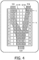
- the flow image processor 30 can then produce a grid-like map of the location and position of the carotid artery branches beneath the probe as indicated in FIGURES 4 and 5 .
- Each box in an 8 by 12 display grid is filled in with a brightness or color when a significant Doppler signal is detected by a corresponding transducer element, and is not illuminated when substantially no Doppler signal is detected.
- the third, fourth, seventh and eighth boxes in the first row of the grid are illuminated in response to the detection of flow in the ICA and ECA by those elements in that row which are over those carotid branches.
- a similar result is obtained from elements 34, 35, 38 and 39 in row 5.
- Boxes corresponding to elements 59-63 of row 8 are illuminated because they detected flow in the CCA below the carotid bifurcation, as is also the case for boxes corresponding to elements 92-94 in row 12.
- FIGURE 4 illustrates, this will present a simple two dimensional grid vessel map of the flow in the carotid artery beneath the array transducer.
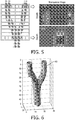
- a similar result can also be obtained in the depth dimension as shown in FIGURE 5 .
- This shows the results from depth-gating the Doppler signal samples from six discrete depths below the elements in the top and bottom rows of the array 12.
- the transverse maps to the right of the array illustration shows faintly illuminated blocks at six depths where the second, third, seventh and eighth elements in the top row have detected flow in the ICA and the ECA.
- the lower map shows a wider, more illuminated set of depth blocks where the center three elements of the bottom row of elements have detected the stronger flow in the CCA which is beneath that row of elements.
- the values of these vertical depth block in each column can be combined in various ways to obtain a display value for a box in the longitudinal display shown to the left of the transverse maps, if desired.
- An object of an implementation of the present invention is to provide real-time feedback to the user such that the user is guided in placing the probe on the neck so that it covers the bifurcation of the carotid artery. Since this is a non-image based system, feedback can be given to the user through a set of indicators on the screen that guides the user to move the probe in the appropriate direction.
- the ideal placement of the probe is when the flow image detector detects a single vessel branch (CCA) at rows 8 & 12 of the grid display and two separate vessel branches (ICA and ECA) in rows 1 & 5 of the grid as shown in FIGURE 4 . The elements in these rows are continuous fired and the flow image processor computes the accumulated Doppler power of the signals received by each element in real time.
- the grid blocks which are illuminated in response to significant Doppler signal returns inform the system of the placement adjustment needed to obtain good probe placement. If the placement is good, the "OK" indicator is highlighted in the probe guidance display of FIGURE 3 . If not, appropriate one of the arrows in the guidance display are highlighted to guide the user in probe placement. An optimal positioning of the probe is achieved when the display grid showing the depth accumulated Doppler power ( FIGURE 4 ) indicates a separation of the vessel segments in the carotid bifurcation.
- the "Probe placement” and “Vessel Mapping" display buttons at the bottom of the guidance display tell the user the current mode of operation, either probe placement or vessel mapping.
- the user taps the Probe placement display button to return the system to that mode and the Probe placement button responds by illuminating. Since approximately 3 seconds worth of Doppler data is required for a single iteration, a guidance indication can be determined and updated in a time of 3 seconds. The maximum time to achieve acceptable placement of the probe over the carotid artery depends on the number of iterations required to successfully place the probe in the proper position for carotid artery stenosis detection.
- the next step is to obtain ultrasound Doppler data from all the elements in the probe array and map the vessels in accordance with the elements which detect flow.
- the accumulated Doppler power is computed as described above in conjunction with FIGURE 5 for the depths of interest to generate a 3D representation of the carotid vessels.
- the 3D representation is produced from the depth values detected by all of the elements and processed by the volume renderer 24 into a 3D display map. As shown in FIGURE 6 , a 3D display map 60 of the bifurcated vessel is displayed.
- Doppler data is acquired from all of the elements to extract the peak systolic velocity which can aid in classification of a stenosis. Additionally if desired a Doppler spectrum can be extracted at a suspected point of stenosis to further aid the diagnosis as described below.
- the probe 10 When the probe 10 has a small aperture, it may not be possible to acquire a sufficiently sized portion of the carotid, its branches and bifurcation in a single acquisition. In such a case multiple volume acquisition is employed to acquire segments of the carotid artery in sub-areas or sub-volumes by movement of the probe along the neck, then stitching the smaller segments together to form the desired vessel map.
- Manual movement of probe implies that there is no calibration, the overlap region may vary among two consecutive acquisitions, and there is also potential variation in the angle and quality of signal acquisition.
- data is acquired in multiple sub-volumes to cover the entire carotid anatomy.
- the carotid vascular anatomy must be reconstructed to verify if the entire carotid anatomy was scanned, and so the sub-volumes must be stitched together. This is done by "stitching" together successively acquired, spatially different but overlapping subvolumes by aligning their matching data in the overlapping region.
- the overlapping region of each subvolume is determined from a match of the time domain Doppler obtained from the individual transducer elements.
- one subvolume may have a column of voxels with flow velocity values of 0, 3, 5, 3, and 0 cm/sec.
- the subvolumes are aligned on the basis of this identity of sequential voxel values.
- Other Doppler spectral characteristic instead of or in addition to velocity can be used to make the match. This stitching is performed purely based on the signal characteristics because relative position of the probe with reference to the neck is not easy to obtain.
- Peak systolic velocity is a clinically accepted diagnostic indicator to grade stenosis according to the following consensus criteria: Degree of stenosis PSV (cm/s) Normal or ⁇ 50 % ⁇ 125 50% - 69% 125-230 >70% >230 Total occlusion No flow
- the probe 10 Since the probe 10 is non imaging, it is difficult for the user to understand how much of the artery cluster under investigation has been covered by a sweep of the probe. It is difficult to interpret from the reconstruction of any of the typical sampled sub-volumes, e.g., (a) (b) or (c) of FIGURE 7 , whether the artery structure has been covered with anatomical cues from a single volume. Therefore, the data from multiple volumes is stitched together to completely reconstruct the vascular anatomy and provide an anatomical basis for artery identification. Anatomical cues from the generated vessel map of the sub-volumes are used as well as signal characteristics to complete the vascular anatomy reconstruction.
- the following steps may be employed in accordance with the present invention to reconstruct the full anatomy.
- the probe 10 is placed in a location L1 resulting in acquisition of sample volume V1.
- the probe is manually moved to location L2, adjacent to L1 such that the resulting new acquisition sample volume V2 is partially overlapped with V1.
- Each volume in this example is a three dimensional matrix containing returned ultrasound echo data.
- further sample volumes Vn are acquired in the same manner, such that the vessel structure of interest is fully covered. Since this is a non-imaging approach, it may not be feasible to know the completion of vessel map reconstruction until the end of the process.
- Vessel map identification is used to identify a vessel segment in a given volume.
- VM a list of unique vessel segments identified using the previous step.
- the number of vessel segments VM i is compared among the sample volumes. This helps to clearly identify the region of overlap in the sample volume where the number of regions is non uniform, such as the volume containing the bifurcation point of the carotid artery, using anatomical information from the reconstruction. It also gives an indication of where to search for matching signal data, e.g., the overlap between FIGURE 7(b) and FIGURE 7(c) can only be where there are two distinct vessels in FIGURE 7(b) .
- the data of all the good spectra from the top most row of each column of one sample volume is extracted in order, and correlated with the data of each of the rows of the subsequent (adjacent) volume.
- a spike in correlation at row k indicates that all the data from row k to the last row of the probe are in the overlapping region. Since the effects of noise are unpredictable on the signal, it may happen that one of the acquisitions of the overlapping volumes is more contaminated by noise than the other. In this case, the overlapping area is assigned to the volume where this area has more analyzable spectra. In the event that the number of such spectra is equal, the overlapping region can be assigned to either volume.
- RM ( i + k ) is R 1 i + k R 2 i + k R 3 i + k ⁇ R p i + k
- Volume data from R k to R p is assigned to the corresponding volume. This yields the volumes to be stitched as S 1 , S 2 and S 3 .
- the volumes to be stitched are stacked in the direction of motion and connected by interpolation and/or smoothing.
- Blood flow in the carotid artery can be laminar or turbulent.
- Laminar flow is uniform, with all blood cells moving at relatively the same speed and in the same direction.
- Turbulent flow is characterized by random chaotic swirling, in which blood cells within the vessel are moving in many directions but typically have a net forward flow.
- Doppler spectra of laminar flow appear as broadening of the spectral line and filling of the spectral window.
- a turbulent flow pattern appears as spectral broadening with components below the baseline.
- Spectral broadening is a term applied to waveform alterations that are representative of turbulent flow. It is defined as the increased distribution of the frequencies present in a Doppler spectrum as illustrated by the Doppler flow spectrograms of FIGURE 8 .
- this type of turbulence is present at the bifurcation point (i.e ., the carotid bulb, equivalent from the point of view of flow characteristics) and at a narrowing or stenosis of the vessel.
- the main way of distinguishing these two cases of turbulence is through the measurement of the peak systolic velocity (PSV).
- PSV peak systolic velocity
- the presence of stenosis is usually characterized by an elevated PSV accompanying turbulence.
- the criteria for dangerous levels of plaque are generally related to percentage of stenosis; also, the degree of stenosis is determined by the peak velocity of the blood as follows: Degree of stenosis PSV (cm/s) Turbulence (Spectral Broadening) Normal ⁇ 125 Normal & High at carotid bulb ⁇ 50% ⁇ 125 High 50% - 69% 125-230 High >70% >230 High Total occlusion No flow Nil Detecting the Doppler shift caused by increased velocity can determine whether there is dangerous plaque present.
- Distinguishing the characteristics of the bifurcation of the carotid artery from the characteristics of a stenosis can be done as follows: Condition/Feature PSV Turbulence (Spectral Broadening) Bifurcations (Carotid bulb) Normal High Stenosis High High This relationship shows that by estimating the turbulence in terms of spectral broadening and the PSV one can easily identify the segments of interest (like bifurcation and a stenosis jet) with the help of suitable thresholds for PSV and spectral broadening. The present invention uses this information to detect the segments of interest without any imaging of the carotid artery.
- the present invention provides an automated method to characterize the turbulence present in the carotid cluster with differentiated degrees of stenosis.
- Experimental results have shown this estimation of stenosis in a segment of interest, together with a combination of turbulence with peak systolic velocity, provide a robust technique for evaluating stenosis.
- Spectral Doppler ultrasound velocimetry involves the systematic analysis of the spectrum of frequencies that constitute the Doppler signal.
- the Doppler signal obtained for clinical use is composed of a range of frequencies with varying amplitude content. Therefore, systematic processing is required before the Doppler shift frequencies are computed.
- the systematic process of FIGURE 9 estimates the two most important parameters to be estimated for stenosis evaluation, the PSV and turbulence.
- Doppler signals are acquired from the volumetric region of the carotid artery as described above and the Doppler signals is pre-processed (74) to remove unwanted noisy signal components.
- the vessel localization step 76 identifies whether the acquired Doppler signals contain vessel information (CCA, ICA, ECA or bifurcation point) or not. This is done with the help of a predefined power threshold for the Doppler power.
- the power in the time domain (the sum of the square of all the values divided by signal length) is computed for all of the sample volumes of the carotid artery. Then the average power is computed from all the sample volumes. Finally the sample volume that exhibits the highest power above the average value is considered as a segment having vessel information.
- the spectral profile extraction at step 82 involves two steps: (i) computing a spectrogram using the spectral Doppler processor 32 and (ii) processing the spectrogram (smoothing, thresholding, noise removal, etc .,) to obtain a good spectral profile.
- the spectrogram is obtained using a Fast Fourier Transform (FFT) based power spectrum with a 20 millisecond Hamming window using 256 data points and 50% overlap. After this a smooth and reproducible maximum frequency envelope is extracted from the generated spectrogram.
- FFT Fast Fourier Transform
- a smooth and reproducible maximum frequency envelope is extracted from the generated spectrogram.
- To obtain a high quality maximum frequency envelop a first order Infinite Impulse Response (IIR) filter is initially applied to the obtained spectrogram.
- IIR Infinite Impulse Response
- a 2D median filter is applied to the pulse waveform obtained from the IIR filter.
- the output of the median filter is used to extract the
- step 88 To estimate PSV in step 88, first a 3D vessel map is created in step 78 from the identified vessel information as described previously. From the vessel map the Doppler angle is estimated in step 86 by piecewise linear fit of the geometrical centroids of the carotid vessel structure obtained from the vessel map. The maximum Doppler shift frequency is also computed from the estimated spectral profile.
- the turbulence is characterized by the spectral broadening which is normally seen in the presence of high flow velocity at the branching of a vessel or in small-diameter vessels.
- Spectral broadening can be estimated by estimating the bandwidth of the spectrum, also referred to as the spectral width.
- Turbulence is characterized by estimating the spectral width and therefore extracting both an upper and a lower trace of the envelope of the spectrogram.
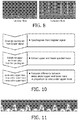
- the turbulence was estimated by using the area between the upper and lower spectral traces as a proportion of the area under the upper spectral trace as described by FIGURE 10 .
- FIGURE 11 illustrates the computation steps involved and an illustration of a traced Doppler spectrogram is shown in FIGURE 11 .
- the concluding determinations of the method of FIGURE 9 are to report the finding of the carotid bifurcation point (92), indication of stenosis (90), or a normal carotid (96) to the user. These determinations are made by comparing the turbulence estimate of spectral width SW from step 84 and the PSV estimate from step 88 to a turbulence threshold T s and a velocity threshold T p in comparison steps 98a, 98b, and 98c.
- a nominal velocity threshold T p is 125 cm/sec, and a nominal turbulence criteria is 0.5. The results of these comparisons are then presented to the user on the display screen.
- an implementation of the present invention provides a method for detecting and characterizing the segments of interest in a carotid artery without any imaging of the vessel.
- the inventive technique makes use of the non-imaging two dimensional array Doppler probe described above and the method of vessel localization previously described, together with Doppler angle estimation for detecting a stenosis and estimating its severity.
- Major elements of the invention include computing the turbulence at various points in the carotid structure and characterizing turbulence with differentiated degrees of stenosis; combining the estimates of turbulence and PSV to identify the segments of interest in a carotid artery; and combining the turbulence and PSV estimates to automatically characterize the stenosis of vessel segments in terms of the degree of stenosis.
Landscapes
- Health & Medical Sciences (AREA)
- Life Sciences & Earth Sciences (AREA)
- Engineering & Computer Science (AREA)
- Public Health (AREA)
- Medical Informatics (AREA)
- General Health & Medical Sciences (AREA)
- Pathology (AREA)
- Biomedical Technology (AREA)
- Molecular Biology (AREA)
- Veterinary Medicine (AREA)
- Heart & Thoracic Surgery (AREA)
- Nuclear Medicine, Radiotherapy & Molecular Imaging (AREA)
- Biophysics (AREA)
- Surgery (AREA)
- Animal Behavior & Ethology (AREA)
- Physics & Mathematics (AREA)
- Radiology & Medical Imaging (AREA)
- Hematology (AREA)
- Physiology (AREA)
- Computer Vision & Pattern Recognition (AREA)
- Vascular Medicine (AREA)
- Gynecology & Obstetrics (AREA)
- Data Mining & Analysis (AREA)
- Databases & Information Systems (AREA)
- Epidemiology (AREA)
- Primary Health Care (AREA)
- Ultra Sonic Daignosis Equipment (AREA)
Applications Claiming Priority (2)
| Application Number | Priority Date | Filing Date | Title |
|---|---|---|---|
| US201361857837P | 2013-07-24 | 2013-07-24 | |
| PCT/IB2014/062790 WO2015011585A1 (en) | 2013-07-24 | 2014-07-02 | Non-imaging two dimensional array probe and system for classifying carotid stenosis |
Publications (2)
| Publication Number | Publication Date |
|---|---|
| EP3024395A1 EP3024395A1 (en) | 2016-06-01 |
| EP3024395B1 true EP3024395B1 (en) | 2017-10-18 |
Family
ID=51357970
Family Applications (1)
| Application Number | Title | Priority Date | Filing Date |
|---|---|---|---|
| EP14752663.6A Active EP3024395B1 (en) | 2013-07-24 | 2014-07-02 | Non-imaging two dimensional array probe and system for classifying carotid stenosis |
Country Status (5)
| Country | Link |
|---|---|
| US (1) | US10945702B2 (enExample) |
| EP (1) | EP3024395B1 (enExample) |
| JP (1) | JP6205056B2 (enExample) |
| CN (1) | CN105491957B (enExample) |
| WO (1) | WO2015011585A1 (enExample) |
Families Citing this family (17)
| Publication number | Priority date | Publication date | Assignee | Title |
|---|---|---|---|---|
| EP3024397B1 (en) * | 2013-07-24 | 2017-12-20 | Koninklijke Philips N.V. | Method for aligning spatially different subvolumes of ultrasonic data of a blood vessel |
| WO2017109080A1 (en) | 2015-12-22 | 2017-06-29 | Koninklijke Philips N.V. | Multi-site continuous ultrasound flow measurement for hemodynamic management |
| EP3381512A1 (en) | 2017-03-30 | 2018-10-03 | Koninklijke Philips N.V. | Determining at least one final two-dimensional image for visualizing an object of interest in a three-dimensional ultrasound volume |
| CN111511286B (zh) * | 2017-10-24 | 2024-03-15 | 皇家飞利浦有限公司 | 对血管狭窄的超声测量 |
| EP3749215A4 (en) | 2018-02-07 | 2021-12-01 | Atherosys, Inc. | APPARATUS AND METHOD FOR GUIDING THE ULTRASONIC ACQUISITION OF PERIPHERAL ARTERIES IN THE CROSS-PLANE |
| WO2019169508A1 (en) | 2018-03-09 | 2019-09-12 | 1929803 Ontario Corp. D/B/A Flosonics Medical | Dynamically controllable patient fluid control device |
| EP3787480A4 (en) | 2018-04-30 | 2022-01-26 | Atherosys, Inc. | METHOD AND APPARATUS FOR THE AUTOMATIC DETECTION OF ATHEROMAS IN PERIPHERAL ARTERIES |
| EP3847480B1 (en) * | 2018-09-07 | 2023-07-19 | Bioprober Corporation | Method and apparatus for detecting flow instability |
| US11559287B2 (en) * | 2018-10-11 | 2023-01-24 | Shenzhen Mindray Bio-Medical Electronics Co., Ltd. | Transducer spectral normalization |
| EP3669786A1 (en) * | 2018-12-17 | 2020-06-24 | Koninklijke Philips N.V. | Systems and methods for guided ultrasound data acquisition |
| US11419585B2 (en) * | 2019-11-18 | 2022-08-23 | GE Precision Healthcare LLC | Methods and systems for turbulence awareness enabled ultrasound scanning |
| US20210177376A1 (en) * | 2019-12-16 | 2021-06-17 | Biosense Webster (Isreal) Ltd. | Guidewire ultrasound (us) probe for a minimally perturbing measurement of blood flow in brain vessel |
| JP7440318B2 (ja) * | 2020-03-26 | 2024-02-28 | 日本光電工業株式会社 | 生体情報モニタ、生体情報表示方法、及びプログラム |
| CN118355446A (zh) * | 2021-08-04 | 2024-07-16 | 加州理工学院 | 血流中的凝块的超声检测 |
| CN114282450B (zh) * | 2021-12-02 | 2025-09-02 | 安徽大学 | 一种各向异性高超声速等离子体湍流中高斯波束的传播特性计算方法 |
| US12213840B2 (en) * | 2022-03-14 | 2025-02-04 | EchoNous, Inc. | Automatically establishing measurement location controls for doppler ultrasound |
| WO2025230899A1 (en) * | 2024-04-29 | 2025-11-06 | Becton, Dickinson And Company | Method and systems to reduce search time of target in stand-alone ultrasound doppler |
Family Cites Families (22)
| Publication number | Priority date | Publication date | Assignee | Title |
|---|---|---|---|---|
| US5474073A (en) * | 1994-11-22 | 1995-12-12 | Advanced Technology Laboratories, Inc. | Ultrasonic diagnostic scanning for three dimensional display |
| US6261233B1 (en) * | 1996-01-05 | 2001-07-17 | Sunlight Medical Ltd. | Method and device for a blood velocity determination |
| EP0883860B1 (en) * | 1996-02-29 | 2006-08-23 | Acuson Corporation | Multiple ultrasound image registration system, method and transducer |
| FR2759892A1 (fr) * | 1996-12-31 | 1998-08-28 | Philips Electronics Nv | Systeme d'echographie ultrasonore pour l'examen des arteres |
| US6524249B2 (en) * | 1998-11-11 | 2003-02-25 | Spentech, Inc. | Doppler ultrasound method and apparatus for monitoring blood flow and detecting emboli |
| IL137447A (en) * | 2000-07-23 | 2007-03-08 | Israel Atomic Energy Comm | Apparatus and method for probing light absorbing agents in biological tissues |
| ATE308922T1 (de) * | 2001-03-02 | 2005-11-15 | Palti Yoram Prof | Gerät zur detektierung arterieller stenose |
| US7285094B2 (en) * | 2002-01-30 | 2007-10-23 | Nohara Timothy J | 3D ultrasonic imaging apparatus and method |
| US20050119573A1 (en) | 2003-11-05 | 2005-06-02 | Boris Vilenkin | Method and system for quantification of arterial stenosis |
| US8388544B2 (en) | 2005-03-17 | 2013-03-05 | General Electric Company | System and method for measuring blood viscosity |
| JP2007289588A (ja) * | 2006-04-21 | 2007-11-08 | Tomoyuki Yamaya | バイパスグラフト評価のための超音波血流診断装置。 |
| JP4945300B2 (ja) * | 2007-04-25 | 2012-06-06 | 株式会社東芝 | 超音波診断装置 |
| US9788813B2 (en) * | 2010-10-13 | 2017-10-17 | Maui Imaging, Inc. | Multiple aperture probe internal apparatus and cable assemblies |
| US20090292208A1 (en) * | 2008-03-03 | 2009-11-26 | Jeffrey Jr R Brooke | Automated detection of asymptomatic carotid stenosis |
| JP5819732B2 (ja) * | 2009-02-05 | 2015-11-24 | パルティ、ヨーラム | 血管における狭窄の検出 |
| CN101485579A (zh) * | 2009-02-17 | 2009-07-22 | 郎鸿志 | 一种超声定位血管治疗装置及控制技术 |
| US8295912B2 (en) | 2009-10-12 | 2012-10-23 | Kona Medical, Inc. | Method and system to inhibit a function of a nerve traveling with an artery |
| WO2013001503A2 (en) | 2011-06-30 | 2013-01-03 | Koninklijke Philips Electronics N.V. | Method and apparatus for automated ultrasonic doppler angle and flow velocity estimation |
| CN103814305B (zh) * | 2011-09-22 | 2017-06-13 | 皇家飞利浦有限公司 | 针对低成本换能器阵列的激励方案 |
| WO2013088320A1 (en) | 2011-12-16 | 2013-06-20 | Koninklijke Philips Electronics N.V. | Automatic blood vessel identification by name |
| CN104114101B (zh) * | 2011-12-16 | 2016-08-24 | 皇家飞利浦有限公司 | 自动多普勒脉动周期选择 |
| WO2015011594A1 (en) | 2013-07-24 | 2015-01-29 | Koninklijke Philips N.V. | Non-imaging two dimensional array probe and system for automated screening of carotid stenosis |
-
2014
- 2014-07-02 EP EP14752663.6A patent/EP3024395B1/en active Active
- 2014-07-02 CN CN201480041333.7A patent/CN105491957B/zh active Active
- 2014-07-02 US US14/906,966 patent/US10945702B2/en active Active
- 2014-07-02 WO PCT/IB2014/062790 patent/WO2015011585A1/en not_active Ceased
- 2014-07-02 JP JP2016528618A patent/JP6205056B2/ja not_active Expired - Fee Related
Non-Patent Citations (1)
| Title |
|---|
| None * |
Also Published As
| Publication number | Publication date |
|---|---|
| EP3024395A1 (en) | 2016-06-01 |
| WO2015011585A1 (en) | 2015-01-29 |
| JP6205056B2 (ja) | 2017-09-27 |
| CN105491957A (zh) | 2016-04-13 |
| US20160157814A1 (en) | 2016-06-09 |
| CN105491957B (zh) | 2019-03-12 |
| US10945702B2 (en) | 2021-03-16 |
| JP2016527022A (ja) | 2016-09-08 |
Similar Documents
| Publication | Publication Date | Title |
|---|---|---|
| EP3024395B1 (en) | Non-imaging two dimensional array probe and system for classifying carotid stenosis | |
| EP3024396B1 (en) | System with two dimensional array probe for automated screening of carotid stenosis | |
| EP3024397B1 (en) | Method for aligning spatially different subvolumes of ultrasonic data of a blood vessel | |
| US9398898B2 (en) | Multiple beam spectral doppler in medical diagnostic ultrasound imaging | |
| US10338203B2 (en) | Classification preprocessing in medical ultrasound shear wave imaging | |
| EP2967490B1 (en) | Ultrasound vector flow imaging (vfi) with curve tracing | |
| EP3863522B1 (en) | Methods and systems for determining complementary ultrasound views | |
| JPH07250835A (ja) | 超音波パルスエコー装置及び該装置を用いた超音波診断装置 | |
| CN111885965A (zh) | 用于三维中的剪切波成像的超声系统 | |
| US20170273658A1 (en) | Acoustic streaming for fluid pool detection and identification | |
| EP4142605B1 (en) | Three dimensional color doppler for ultrasonic volume flow measurement | |
| US20190231320A1 (en) | Ultrasonic shear wave imaging with background motion compensation | |
| US20090299179A1 (en) | Method For Detecting Cardiac Transplant Rejection | |
| CN112672696A (zh) | 用于跟踪超声图像中的工具的系统和方法 | |
| Ricci et al. | Toward Automatic Measurement of Carotid Blood Velocity | |
| EP3340887B1 (en) | Spectral doppler processing with adaptive sample window size |
Legal Events
| Date | Code | Title | Description |
|---|---|---|---|
| PUAI | Public reference made under article 153(3) epc to a published international application that has entered the european phase |
Free format text: ORIGINAL CODE: 0009012 |
|
| 17P | Request for examination filed |
Effective date: 20160224 |
|
| AK | Designated contracting states |
Kind code of ref document: A1 Designated state(s): AL AT BE BG CH CY CZ DE DK EE ES FI FR GB GR HR HU IE IS IT LI LT LU LV MC MK MT NL NO PL PT RO RS SE SI SK SM TR |
|
| AX | Request for extension of the european patent |
Extension state: BA ME |
|
| DAX | Request for extension of the european patent (deleted) | ||
| RIC1 | Information provided on ipc code assigned before grant |
Ipc: A61B 8/08 20060101ALI20170406BHEP Ipc: A61B 8/00 20060101ALI20170406BHEP Ipc: A61B 8/06 20060101AFI20170406BHEP |
|
| GRAP | Despatch of communication of intention to grant a patent |
Free format text: ORIGINAL CODE: EPIDOSNIGR1 |
|
| INTG | Intention to grant announced |
Effective date: 20170515 |
|
| GRAS | Grant fee paid |
Free format text: ORIGINAL CODE: EPIDOSNIGR3 |
|
| GRAA | (expected) grant |
Free format text: ORIGINAL CODE: 0009210 |
|
| AK | Designated contracting states |
Kind code of ref document: B1 Designated state(s): AL AT BE BG CH CY CZ DE DK EE ES FI FR GB GR HR HU IE IS IT LI LT LU LV MC MK MT NL NO PL PT RO RS SE SI SK SM TR |
|
| REG | Reference to a national code |
Ref country code: GB Ref legal event code: FG4D |
|
| REG | Reference to a national code |
Ref country code: CH Ref legal event code: EP |
|
| REG | Reference to a national code |
Ref country code: AT Ref legal event code: REF Ref document number: 937238 Country of ref document: AT Kind code of ref document: T Effective date: 20171115 Ref country code: IE Ref legal event code: FG4D |
|
| REG | Reference to a national code |
Ref country code: DE Ref legal event code: R096 Ref document number: 602014016021 Country of ref document: DE |
|
| REG | Reference to a national code |
Ref country code: DE Ref legal event code: R084 Ref document number: 602014016021 Country of ref document: DE |
|
| REG | Reference to a national code |
Ref country code: GB Ref legal event code: 746 Effective date: 20180111 |
|
| REG | Reference to a national code |
Ref country code: NL Ref legal event code: MP Effective date: 20171018 |
|
| REG | Reference to a national code |
Ref country code: LT Ref legal event code: MG4D |
|
| REG | Reference to a national code |
Ref country code: AT Ref legal event code: MK05 Ref document number: 937238 Country of ref document: AT Kind code of ref document: T Effective date: 20171018 |
|
| PG25 | Lapsed in a contracting state [announced via postgrant information from national office to epo] |
Ref country code: NL Free format text: LAPSE BECAUSE OF FAILURE TO SUBMIT A TRANSLATION OF THE DESCRIPTION OR TO PAY THE FEE WITHIN THE PRESCRIBED TIME-LIMIT Effective date: 20171018 |
|
| PG25 | Lapsed in a contracting state [announced via postgrant information from national office to epo] |
Ref country code: SE Free format text: LAPSE BECAUSE OF FAILURE TO SUBMIT A TRANSLATION OF THE DESCRIPTION OR TO PAY THE FEE WITHIN THE PRESCRIBED TIME-LIMIT Effective date: 20171018 Ref country code: LT Free format text: LAPSE BECAUSE OF FAILURE TO SUBMIT A TRANSLATION OF THE DESCRIPTION OR TO PAY THE FEE WITHIN THE PRESCRIBED TIME-LIMIT Effective date: 20171018 Ref country code: FI Free format text: LAPSE BECAUSE OF FAILURE TO SUBMIT A TRANSLATION OF THE DESCRIPTION OR TO PAY THE FEE WITHIN THE PRESCRIBED TIME-LIMIT Effective date: 20171018 Ref country code: ES Free format text: LAPSE BECAUSE OF FAILURE TO SUBMIT A TRANSLATION OF THE DESCRIPTION OR TO PAY THE FEE WITHIN THE PRESCRIBED TIME-LIMIT Effective date: 20171018 Ref country code: NO Free format text: LAPSE BECAUSE OF FAILURE TO SUBMIT A TRANSLATION OF THE DESCRIPTION OR TO PAY THE FEE WITHIN THE PRESCRIBED TIME-LIMIT Effective date: 20180118 |
|
| PG25 | Lapsed in a contracting state [announced via postgrant information from national office to epo] |
Ref country code: LV Free format text: LAPSE BECAUSE OF FAILURE TO SUBMIT A TRANSLATION OF THE DESCRIPTION OR TO PAY THE FEE WITHIN THE PRESCRIBED TIME-LIMIT Effective date: 20171018 Ref country code: GR Free format text: LAPSE BECAUSE OF FAILURE TO SUBMIT A TRANSLATION OF THE DESCRIPTION OR TO PAY THE FEE WITHIN THE PRESCRIBED TIME-LIMIT Effective date: 20180119 Ref country code: RS Free format text: LAPSE BECAUSE OF FAILURE TO SUBMIT A TRANSLATION OF THE DESCRIPTION OR TO PAY THE FEE WITHIN THE PRESCRIBED TIME-LIMIT Effective date: 20171018 Ref country code: AT Free format text: LAPSE BECAUSE OF FAILURE TO SUBMIT A TRANSLATION OF THE DESCRIPTION OR TO PAY THE FEE WITHIN THE PRESCRIBED TIME-LIMIT Effective date: 20171018 Ref country code: IS Free format text: LAPSE BECAUSE OF FAILURE TO SUBMIT A TRANSLATION OF THE DESCRIPTION OR TO PAY THE FEE WITHIN THE PRESCRIBED TIME-LIMIT Effective date: 20180218 Ref country code: BG Free format text: LAPSE BECAUSE OF FAILURE TO SUBMIT A TRANSLATION OF THE DESCRIPTION OR TO PAY THE FEE WITHIN THE PRESCRIBED TIME-LIMIT Effective date: 20180118 Ref country code: HR Free format text: LAPSE BECAUSE OF FAILURE TO SUBMIT A TRANSLATION OF THE DESCRIPTION OR TO PAY THE FEE WITHIN THE PRESCRIBED TIME-LIMIT Effective date: 20171018 |
|
| REG | Reference to a national code |
Ref country code: DE Ref legal event code: R097 Ref document number: 602014016021 Country of ref document: DE |
|
| REG | Reference to a national code |
Ref country code: FR Ref legal event code: PLFP Year of fee payment: 5 |
|
| PG25 | Lapsed in a contracting state [announced via postgrant information from national office to epo] |
Ref country code: SK Free format text: LAPSE BECAUSE OF FAILURE TO SUBMIT A TRANSLATION OF THE DESCRIPTION OR TO PAY THE FEE WITHIN THE PRESCRIBED TIME-LIMIT Effective date: 20171018 Ref country code: CZ Free format text: LAPSE BECAUSE OF FAILURE TO SUBMIT A TRANSLATION OF THE DESCRIPTION OR TO PAY THE FEE WITHIN THE PRESCRIBED TIME-LIMIT Effective date: 20171018 Ref country code: EE Free format text: LAPSE BECAUSE OF FAILURE TO SUBMIT A TRANSLATION OF THE DESCRIPTION OR TO PAY THE FEE WITHIN THE PRESCRIBED TIME-LIMIT Effective date: 20171018 Ref country code: DK Free format text: LAPSE BECAUSE OF FAILURE TO SUBMIT A TRANSLATION OF THE DESCRIPTION OR TO PAY THE FEE WITHIN THE PRESCRIBED TIME-LIMIT Effective date: 20171018 |
|
| PLBE | No opposition filed within time limit |
Free format text: ORIGINAL CODE: 0009261 |
|
| STAA | Information on the status of an ep patent application or granted ep patent |
Free format text: STATUS: NO OPPOSITION FILED WITHIN TIME LIMIT |
|
| PG25 | Lapsed in a contracting state [announced via postgrant information from national office to epo] |
Ref country code: SM Free format text: LAPSE BECAUSE OF FAILURE TO SUBMIT A TRANSLATION OF THE DESCRIPTION OR TO PAY THE FEE WITHIN THE PRESCRIBED TIME-LIMIT Effective date: 20171018 Ref country code: PL Free format text: LAPSE BECAUSE OF FAILURE TO SUBMIT A TRANSLATION OF THE DESCRIPTION OR TO PAY THE FEE WITHIN THE PRESCRIBED TIME-LIMIT Effective date: 20171018 Ref country code: RO Free format text: LAPSE BECAUSE OF FAILURE TO SUBMIT A TRANSLATION OF THE DESCRIPTION OR TO PAY THE FEE WITHIN THE PRESCRIBED TIME-LIMIT Effective date: 20171018 |
|
| 26N | No opposition filed |
Effective date: 20180719 |
|
| PG25 | Lapsed in a contracting state [announced via postgrant information from national office to epo] |
Ref country code: SI Free format text: LAPSE BECAUSE OF FAILURE TO SUBMIT A TRANSLATION OF THE DESCRIPTION OR TO PAY THE FEE WITHIN THE PRESCRIBED TIME-LIMIT Effective date: 20171018 |
|
| REG | Reference to a national code |
Ref country code: CH Ref legal event code: PL |
|
| PG25 | Lapsed in a contracting state [announced via postgrant information from national office to epo] |
Ref country code: MC Free format text: LAPSE BECAUSE OF FAILURE TO SUBMIT A TRANSLATION OF THE DESCRIPTION OR TO PAY THE FEE WITHIN THE PRESCRIBED TIME-LIMIT Effective date: 20171018 Ref country code: LU Free format text: LAPSE BECAUSE OF NON-PAYMENT OF DUE FEES Effective date: 20180702 |
|
| REG | Reference to a national code |
Ref country code: BE Ref legal event code: MM Effective date: 20180731 |
|
| REG | Reference to a national code |
Ref country code: IE Ref legal event code: MM4A |
|
| PG25 | Lapsed in a contracting state [announced via postgrant information from national office to epo] |
Ref country code: LI Free format text: LAPSE BECAUSE OF NON-PAYMENT OF DUE FEES Effective date: 20180731 Ref country code: IE Free format text: LAPSE BECAUSE OF NON-PAYMENT OF DUE FEES Effective date: 20180702 Ref country code: CH Free format text: LAPSE BECAUSE OF NON-PAYMENT OF DUE FEES Effective date: 20180731 |
|
| PG25 | Lapsed in a contracting state [announced via postgrant information from national office to epo] |
Ref country code: BE Free format text: LAPSE BECAUSE OF NON-PAYMENT OF DUE FEES Effective date: 20180731 |
|
| PG25 | Lapsed in a contracting state [announced via postgrant information from national office to epo] |
Ref country code: MT Free format text: LAPSE BECAUSE OF NON-PAYMENT OF DUE FEES Effective date: 20180702 |
|
| PG25 | Lapsed in a contracting state [announced via postgrant information from national office to epo] |
Ref country code: TR Free format text: LAPSE BECAUSE OF FAILURE TO SUBMIT A TRANSLATION OF THE DESCRIPTION OR TO PAY THE FEE WITHIN THE PRESCRIBED TIME-LIMIT Effective date: 20171018 |
|
| PG25 | Lapsed in a contracting state [announced via postgrant information from national office to epo] |
Ref country code: PT Free format text: LAPSE BECAUSE OF FAILURE TO SUBMIT A TRANSLATION OF THE DESCRIPTION OR TO PAY THE FEE WITHIN THE PRESCRIBED TIME-LIMIT Effective date: 20171018 |
|
| PG25 | Lapsed in a contracting state [announced via postgrant information from national office to epo] |
Ref country code: CY Free format text: LAPSE BECAUSE OF FAILURE TO SUBMIT A TRANSLATION OF THE DESCRIPTION OR TO PAY THE FEE WITHIN THE PRESCRIBED TIME-LIMIT Effective date: 20171018 Ref country code: HU Free format text: LAPSE BECAUSE OF FAILURE TO SUBMIT A TRANSLATION OF THE DESCRIPTION OR TO PAY THE FEE WITHIN THE PRESCRIBED TIME-LIMIT; INVALID AB INITIO Effective date: 20140702 Ref country code: MK Free format text: LAPSE BECAUSE OF NON-PAYMENT OF DUE FEES Effective date: 20171018 |
|
| PG25 | Lapsed in a contracting state [announced via postgrant information from national office to epo] |
Ref country code: AL Free format text: LAPSE BECAUSE OF FAILURE TO SUBMIT A TRANSLATION OF THE DESCRIPTION OR TO PAY THE FEE WITHIN THE PRESCRIBED TIME-LIMIT Effective date: 20171018 |
|
| PGFP | Annual fee paid to national office [announced via postgrant information from national office to epo] |
Ref country code: IT Payment date: 20230721 Year of fee payment: 10 |
|
| PGFP | Annual fee paid to national office [announced via postgrant information from national office to epo] |
Ref country code: FR Payment date: 20230725 Year of fee payment: 10 |
|
| PG25 | Lapsed in a contracting state [announced via postgrant information from national office to epo] |
Ref country code: FR Free format text: LAPSE BECAUSE OF NON-PAYMENT OF DUE FEES Effective date: 20240731 |
|
| PG25 | Lapsed in a contracting state [announced via postgrant information from national office to epo] |
Ref country code: IT Free format text: LAPSE BECAUSE OF NON-PAYMENT OF DUE FEES Effective date: 20240702 |
|
| PGFP | Annual fee paid to national office [announced via postgrant information from national office to epo] |
Ref country code: DE Payment date: 20250728 Year of fee payment: 12 |
|
| PGFP | Annual fee paid to national office [announced via postgrant information from national office to epo] |
Ref country code: GB Payment date: 20250722 Year of fee payment: 12 |