EP3024334B1 - Moulding food products from a pumpable foodstuff mass - Google Patents
Moulding food products from a pumpable foodstuff mass Download PDFInfo
- Publication number
- EP3024334B1 EP3024334B1 EP14753324.4A EP14753324A EP3024334B1 EP 3024334 B1 EP3024334 B1 EP 3024334B1 EP 14753324 A EP14753324 A EP 14753324A EP 3024334 B1 EP3024334 B1 EP 3024334B1
- Authority
- EP
- European Patent Office
- Prior art keywords
- grinder
- mass
- mould
- drum
- orificed
- Prior art date
- Legal status (The legal status is an assumption and is not a legal conclusion. Google has not performed a legal analysis and makes no representation as to the accuracy of the status listed.)
- Active
Links
- 238000000465 moulding Methods 0.000 title claims description 41
- 235000013305 food Nutrition 0.000 title description 23
- 238000000227 grinding Methods 0.000 claims description 104
- 238000009434 installation Methods 0.000 claims description 66
- 238000000034 method Methods 0.000 claims description 37
- 230000033001 locomotion Effects 0.000 claims description 25
- 230000008569 process Effects 0.000 claims description 18
- 235000020993 ground meat Nutrition 0.000 claims description 17
- 238000003491 array Methods 0.000 claims description 15
- 238000004891 communication Methods 0.000 claims description 13
- 238000012546 transfer Methods 0.000 claims description 13
- 239000000463 material Substances 0.000 claims description 8
- 230000001360 synchronised effect Effects 0.000 claims description 5
- 230000000737 periodic effect Effects 0.000 claims description 3
- 239000000047 product Substances 0.000 description 41
- 235000013372 meat Nutrition 0.000 description 22
- 239000002184 metal Substances 0.000 description 19
- 239000000203 mixture Substances 0.000 description 16
- 230000009471 action Effects 0.000 description 15
- 238000004519 manufacturing process Methods 0.000 description 13
- 238000013461 design Methods 0.000 description 10
- 230000007246 mechanism Effects 0.000 description 8
- 238000013459 approach Methods 0.000 description 7
- 235000015278 beef Nutrition 0.000 description 7
- 230000005540 biological transmission Effects 0.000 description 7
- 239000002245 particle Substances 0.000 description 6
- 230000001133 acceleration Effects 0.000 description 5
- 230000008901 benefit Effects 0.000 description 5
- 235000013622 meat product Nutrition 0.000 description 5
- 230000004913 activation Effects 0.000 description 4
- 230000009286 beneficial effect Effects 0.000 description 4
- 239000000919 ceramic Substances 0.000 description 4
- 125000006850 spacer group Chemical group 0.000 description 4
- 238000010411 cooking Methods 0.000 description 3
- 230000003111 delayed effect Effects 0.000 description 3
- 230000000694 effects Effects 0.000 description 3
- 230000004323 axial length Effects 0.000 description 2
- 230000008859 change Effects 0.000 description 2
- 239000007795 chemical reaction product Substances 0.000 description 2
- 230000001427 coherent effect Effects 0.000 description 2
- 238000005520 cutting process Methods 0.000 description 2
- 238000006073 displacement reaction Methods 0.000 description 2
- 238000009826 distribution Methods 0.000 description 2
- 230000006870 function Effects 0.000 description 2
- 235000015220 hamburgers Nutrition 0.000 description 2
- 235000013594 poultry meat Nutrition 0.000 description 2
- 238000002203 pretreatment Methods 0.000 description 2
- 238000003860 storage Methods 0.000 description 2
- 238000011144 upstream manufacturing Methods 0.000 description 2
- 241000251468 Actinopterygii Species 0.000 description 1
- 241001474374 Blennius Species 0.000 description 1
- 241000233866 Fungi Species 0.000 description 1
- 240000007594 Oryza sativa Species 0.000 description 1
- 235000007164 Oryza sativa Nutrition 0.000 description 1
- 244000061456 Solanum tuberosum Species 0.000 description 1
- 235000002595 Solanum tuberosum Nutrition 0.000 description 1
- 238000004458 analytical method Methods 0.000 description 1
- 230000015572 biosynthetic process Effects 0.000 description 1
- 229910010293 ceramic material Inorganic materials 0.000 description 1
- 239000002131 composite material Substances 0.000 description 1
- 238000010276 construction Methods 0.000 description 1
- 230000008021 deposition Effects 0.000 description 1
- 238000007599 discharging Methods 0.000 description 1
- 230000009977 dual effect Effects 0.000 description 1
- 235000013410 fast food Nutrition 0.000 description 1
- 230000002349 favourable effect Effects 0.000 description 1
- 239000012467 final product Substances 0.000 description 1
- 238000012423 maintenance Methods 0.000 description 1
- 230000014759 maintenance of location Effects 0.000 description 1
- 230000013011 mating Effects 0.000 description 1
- 235000015277 pork Nutrition 0.000 description 1
- 239000011148 porous material Substances 0.000 description 1
- 235000012015 potatoes Nutrition 0.000 description 1
- 238000004321 preservation Methods 0.000 description 1
- 102000004169 proteins and genes Human genes 0.000 description 1
- 108090000623 proteins and genes Proteins 0.000 description 1
- 238000005086 pumping Methods 0.000 description 1
- 230000009467 reduction Effects 0.000 description 1
- 235000009566 rice Nutrition 0.000 description 1
- 238000007789 sealing Methods 0.000 description 1
- 235000014347 soups Nutrition 0.000 description 1
- 230000003068 static effect Effects 0.000 description 1
- 238000012360 testing method Methods 0.000 description 1
- 235000013311 vegetables Nutrition 0.000 description 1
Images


Classifications
-
- A—HUMAN NECESSITIES
- A22—BUTCHERING; MEAT TREATMENT; PROCESSING POULTRY OR FISH
- A22C—PROCESSING MEAT, POULTRY, OR FISH
- A22C7/00—Apparatus for pounding, forming, or pressing meat, sausage-meat, or meat products
- A22C7/0023—Pressing means
- A22C7/003—Meat-moulds
- A22C7/0069—Pressing and moulding by means of a drum
-
- A—HUMAN NECESSITIES
- A22—BUTCHERING; MEAT TREATMENT; PROCESSING POULTRY OR FISH
- A22C—PROCESSING MEAT, POULTRY, OR FISH
- A22C17/00—Other devices for processing meat or bones
- A22C17/0006—Cutting or shaping meat
- A22C17/0026—Mincing and grinding meat
-
- A—HUMAN NECESSITIES
- A22—BUTCHERING; MEAT TREATMENT; PROCESSING POULTRY OR FISH
- A22C—PROCESSING MEAT, POULTRY, OR FISH
- A22C7/00—Apparatus for pounding, forming, or pressing meat, sausage-meat, or meat products
- A22C7/0023—Pressing means
- A22C7/003—Meat-moulds
- A22C7/0076—Devices for making meat patties
Definitions
- the present invention relates to installations and methods for moulding food products from a pumpable foodstuff mass.
- the invention is advantageously employed for the manufacture of meat products from a pumpable meat mass, e.g. a ground beef mass, for the manufacture of meat patties.
- a known method for manufacture of e.g. meat patties involves the use of an installation having a frame and a mould drum with an outer circumferential drum surface and a longitudinal drum rotation axis, often a horizontal axis.
- the drum is rotatably supported by the frame to revolve about the drum rotation axis.
- the drum has in the drum surface multiple mould cavities, each having a filling opening for the introduction of foodstuff mass, e.g. ground beef mass, into the mould cavity.
- a mould drum drive is coupled to the drum to drive the drum in a rotation direction.
- a mass feed member is stationary arranged at a fill position.
- This mass feed member has a single chamber with an inlet for the foodstuff mass to introduce foodstuff mass into the chamber and with a mouth facing the drum surface that is provided with the mould cavities.
- the mass feed member is adapted to transfer mass from the chamber into the passing mould cavities of the rotating mould drum when the filling opening of a mould cavity is in communication with the mouth at said fill position.
- the mass that has been filled into a mould cavity remains in said cavity for a while, commonly the installation has a closure member that extends in downstream direction from the mass feed member at the fill position and temporarily keeps the filled mould cavities closed downstream of the fill position, e.g. to allow the mass to become a more coherent food product.
- the mass in the mould cavity forms the food product, e.g. the meat patty.
- the installation comprises a pump that is connected to the inlet of the mass feed member and is adapted to feed foodstuff mass under pressure into the chamber of the mass feed member.
- a food products release or knock-out mechanism is provided, e.g. associated with the mould drum, and is adapted to cause or facilitate removal of the food product at a product removal position that is downstream of the fill position. It is for example known to provide air channels in the drum that extend to the cavities and allow to selectively introduce air that has been supplied from a manifold at a head end of the drum via said channels to between the drum and the product in order to facilitate the release thereof from the mould cavity.
- Other release or removal mechanisms e.g. using a mechanical ejector, are also known in the art.
- the production of moulded food products, e.g. meat patties, with such installations generally includes:
- Some small capacity prior art moulding devices of the design mentioned above have a drum of minimal axial length that is only provided with a single circumferential array of mould cavities that are arranged at different circumferential positions on the drum surface.
- An example thereof is shown in US 3137029 .
- mould cavities are arranged in the drum surface in a mould cavities pattern with cavities at multiple, e.g. two, or four or more, longitudinal positions when seen in longitudinal direction of the drum and at multiple circumferential positions when seen in circumferential position of the drum.
- mould cavities are of identical dimensions, e.g. circular contoured cavities, although other embodiments with non-identical cavities are known as well. Examples of known high capacity food product moulding installations and methods are found in e.g. WO 0030458 and WO2004002229 .
- drum type moulding installations allow for a high production capacity compared to well-known slide-plate moulding devices, wherein a cyclically driven mould plate with a row of mould cavities is cycled back and forth between a fill position and a release or knock-out position. At the fill position the row of mould cavities in the reciprocating plate is filled with foodstuff mass.
- This is for example illustrated in US 4356595 .
- a slide-plate moulding device wherein the plate has a row of mould cavities and for each cavity the mass feed member is provided with a rotary driven orificed grinder body having a grinding face that cooperates with a stationary grinder member.
- the mass flows through the orifices in the grinder body whereof the outlets form the mouth, so that the exiting mass flows directly into the cavity of the plate.
- the present invention amongst others aims to provide measures that resolve, or at least reduce, undesirable non-uniformity of the moulded food products, for example of products that have been obtained with a high capacity drum moulding installation.
- the non-uniformity may relate to the shape but also to other aspects of the product, e.g. the composition, such as the density, which may influence other aspects like the later cooking or frying, or the taste in general.
- the present invention amongst others aims to provide measures that allow for enhanced versatility and/or control with regard to the characteristics of the formed product, e.g. in view of the above mentioned density, taste, frying behaviour, etc.
- the present invention also aims to provide alternative mass feed members to be used in a moulding device for food products, which mass feed members may be used to attain one or more of the above aims.
- the invention is primarily aimed at products formed of ground meat mass, e.g. beef or poultry meat, but is also seen as of interest for other foodstuff masses, e.g. fibrous foodstuff masses.
- the foodstuff mass may include, or primarily be composed of, foodstuff like fish meat, potatoes, rice, (leguminous) vegetables (e.g. soy), seaweeds, nuts, fungi, etc.
- the invention provides an installation for moulding of three dimensional products from a mass of pumpable foodstuff material, for example from ground meat, according to the preamble of claim 1 which is based on US5021025 .
- the invention provides an installation according to claim 1.
- the invention achieves the filling of a mould cavity via multiple outlet orifices, preferably rather small diameter orifices, for example orifices having a diameter in the range between 2 and 6 millimeters.
- the mass feed member is provided with multiple mobile grinder members and one or more orificed grinder bodies that cooperate therewith. This allows for an effective grinding of the mass in the mass feed member and/or allows for a dislodging of any mass particles that get jammed in an orifice of the grinder body.
- each mobile grinder is a rotary grinder member and the associated grinder dive and grinder drive controller are adapted to rotate the rotary grinder members.
- the rotation of the mobile grinder member is a rotation about an axis but in another embodiment the rotation comprises a spiralling motion of the grinder member or similar motion.
- each mobile grinder member is a rotary grinder member that is rotatable about an axis.
- Rotary grinder members are generally known in the field of grinding, e.g. for grinding meat, so that this design allows to benefit from existing knowledge in the field of meat grinding. Also this design is highly reliable and practical to integrate in a mass feed member.
- the mould member is a mould drum, which mould drum has an outer circumferential drum surface with a curvature and a longitudinal drum rotation axis.
- the drum is rotatably supported by the frame to revolve about the drum rotation axis, e.g. a horizontal axis.
- the mould drum has in the drum surface a pattern of multiple mould cavities, which pattern includes multiple arrays of mould cavities at distinct positions in the longitudinal drum rotation axis, with - in each array - multiple mould cavities at spaced location in circumferential direction of the drum surface.
- Each mould cavity has an opening in the outer circumferential drum surface for the transfer of foodstuff mass into the mould cavity and for the later removal of the moulded product from the mould cavity.
- the orificed mouth body has a curved outlet face corresponding to the curvature of a mould drum, e.g. with a plastic orificed body part that forms the outlet face of the mouth body.
- the grinder body is integrated with the orificed mouth body, so that the grinder body forms the side facing away from the mould member. This allows for the grinding to take place in immediate vicinity of the outlet orifices, which enhances the effectiveness of the action of the mobile grinder members in view of the reliable flow of mass through the orificed mouth body.
- the orificed mouth body is provided with a valve, e.g. incorporated in the orificed mouth body, which valve is adapted to open and close orifices in the orificed mouth body independent from operation of the mobile grinder members.
- a valve e.g. incorporated in the orificed mouth body, which valve is adapted to open and close orifices in the orificed mouth body independent from operation of the mobile grinder members.
- the valve action is used to trigger the start of a filling event, with the grinding action being done at any suitable moment, preferably during actual flow of mass through the outlet orifices and not during standstill of mass when the valve is closed.
- the mobile grinder members are dimensioned such that each of them covers only a fraction, e.g.
- the grinder member comprises a grinding blade having a main plane that is angled relative to the grinder face, e.g. perpendicular to the grinder face.
- the valve comprises an orificed valve plate that is movable in its plane between an opened and closed position.
- the orificed valve plate is integrated with the grinder body, so that the multiple mobile grinder members cooperate with an element that is a combined valve plate and grinder body. This arrangement allows to avoid any clogging of orifices in this element and so assures the reliable passage of mass via the mouth body into the mould cavities.
- the motion of the valve plate between its opened and closed position may be in the mentioned perpendicular axis direction, but could e.g. also be at right angles thereto so in the direction of the path of motion of the mould member.
- valve plate orifices may be similar in cross-section to the adjoining outlet orifices in the mouth body, but one can also envisage that the valve plate orifices are differently shaped, e.g. slotted orifices in the valve plate and cylindrical orifices in the mouth body with the slots being longer than the diameter of the outlet orifices.
- the slotted orifices extend with their length in the mentioned perpendicular axis direction.
- the element combining a valve plate and grinder body may have orifices in a region that is not covered by any grinder member when the element is at standstill in open position of the valve, e.g. in regions between adjacent grinder members, e.g. between adjacent circular grinder members. It is then considered advantageous that the element is reciprocated at least once per filling event in the perpendicular axis direction over such a stroke that each orifice in the element passes underneath one of the mobile grinder members such that any clogging of orifices in the element is dealt with by cutting and/or dislodging mass particles that caused the clogging.
- Such a reciprocating motion can be performed e.g.
- each rotary grinder member is mounted on a rotary shaft that extends at right angles to the grinding face. This allows for a simple and reliable structure.
- the shaft protrudes from the chamber of the mass feed member. It is preferred for the protruding shaft end to be connected to the grinder drive, so that the drive is outside the chamber which allows for a simple construction and ease of maintenance.
- each mobile grinder member comprises at least one blade forming an edge that cooperates with the grinding face, e.g. the blade having a main surface that is angled to the grinding face so as to not impair the flow of mass towards the mouth body.
- the orificed mouth body comprises a plastic orificed body part that forms an outlet face of the mouth body that is adjacent the path of the mould member, e.g. having a curved outlet face corresponding to the curvature of a mobile mould member embodied as a drum.
- the plastic embodiment allows for ease of manufacture and avoids undue wear of the mobile mould member.
- each mobile grinder member has an associated independently controllable grinder drive allowing to independently operate each mobile grinder member.
- This e.g. allows for independent timing of the operation of the mobile grinder members and/or for independent speed control of the mobile grinder members, etc.
- This may e.g. be of use when filling events of mould cavities passing the mouth at different perpendicular axis positions are not taking place at the same time, e.g. with mould cavities arranged in staggered patterns on the mould drum.
- the mass feed member is provided with multiple orificed grinder bodies at distinct perpendicular axis positions when seen perpendicular to the path of the mould member, said positions each corresponding to the perpendicular axis position of an array of mould cavities of the mould member, preferably the grinder bodies being exchangeable mounted and/or positionable at different positions in the perpendicular axis direction relative to the mass feed member.
- the grinder body is provided with multiple groups of orifices, each group having orifice inlets arranged within a region of the grinding face along which a mobile grinder member passes, e.g. a rotary grinder member, with one region being spaced from an adjacent region, and wherein the grinder body is integrated with the orificed mouth body, and wherein - at the outlet face of the mouth body - the orifices having orifice outlets that are evenly distributed in said perpendicular axis direction.
- the grinding face is a planar face.
- the grinding face may also have a relief and/or curvature.
- the grinding face may be curved in one dimension, e.g. along a longitudinal axis thereof, for example said axis being parallel to the rotation axis of a moulding drum forming the mould member of the installation.
- the curvature of the grinding face in a direction transverse to its longitudinal extent, has as its centre the rotation axis of the moulding drum. This latter arrangement may, in a suitable embodiment of the orifices, allow for uniformity of the length of the orifices or bores between the grinding face and the outlet face, which may enhance uniformity of flow of mass into the mould cavity.
- the invention also relates to a method for moulding of three dimensional products from a mass of pumpable foodstuff material, for example from ground meat, according to claim 12, wherein use is made of an installation as described herein.
- the installation is embodied and operated such that the start of the filling event and thus of the first flow of mass into the mould cavity takes place only after a timed delay relative to the initial moment of communication between the outlet orifices and the mould cavity.
- the present invention envisages that the combination of a an orificed mouth body, a grinder device action, and a delayed start of the filling event, which aspects are in an embodiment completely linked to one another, allows to avoid or at least reduce the problem of undesirable changes to the shape of the formed product during further treatment, e.g. cooking or frying.
- the filling event only starts at a moment that the flow into the mould cavity occupies a significant part of the filling opening of the mould cavity, which filling is then effected by passing the mass through multiple outlet orifices, wherein the grinding action assures the proper flow through said outlet orifices.
- the grinder device controller causes intermittent operation of the grinder device that is synchronized with the movement of the mould member and/or the opening of a valve when present, such that the foodstuff mass is subjected to the grinding process during the filling event as the grinder drive drives the mobile grinder member at a grinding speed during the filling event and such that in an intermediate period between successive filling events the grinder device is halted or operated at a slower speed relative to the grinding speed, preferably halted.
- This embodiment assures or enhances that by halting or slowing down the grinder in the intermediate period, (which may be very short as drum moulding devices are already operated so as to have successive starts of filling events at an interval of e.g.
- the foodstuff mass is not "overworked" by the grinder device during the intermediate period.
- This approach also avoids or at least reduces any problems with the generation of heat as is may result from operation of the grinder, which heat may unduly affect the foodstuff mass.
- the grinder device controller is configured, e.g. programmed, to start the grinding process by bringing the mobile grinder member to said grinding speed after the effective cross-sectional outflow area has reached a predetermined value or after a valve, when present, has been opened.
- the mobile grinder member only starts the actual grinding action once there is flow into the mould cavity. So the grinder is not started as soon as there is a first communication between orifices of the grinder body and the mould cavity, and not even prior to that. The grinder action is thus delayed, so that grinding is done whilst there is flow of mass through the orifices of the grinder, thereby avoiding or reducing overworking of the foodstuff mass.
- the outlet orifices in the orificed mouth body are advantageously dimensioned and oriented so as to obtain a desired inflow of mass into the mould cavity.
- some of the outlet orifices may have an inclination so that the mass enters into the mould cavity at an oblique angle, e.g. some outlet orifices having a component that is directed counter to the mould member motion and/or some orifices may have an inclination directed along the mould member motion.
- Some outlet orifices may be directed at right angles to the path of the mould member motion.
- Some outlet orifices may be directed to emit mass towards a circumferential wall portion of the mould cavity, whereas other outlet orifices are directed to emit mass towards a centrally located bottom wall portion of the mould cavity.
- the skilled person may also vary the cross-section and cross-sectional shape of the outlet orifices, e.g. with smaller orifices that provide the mass to form an outer region of the product (e.g. a circumferential region of a meat patty) and with larger orifices that provide mass to form an inner region of the product.
- the cross-section and orientation may vary over the length of an outlet orifice, e.g. with sections that are angled with respect to one another.
- the orificed mouth body is integrated with the orificed grinder body, so that the mass is ground as it passes into the orifices in the grinder body and then continues through the integrated orificed mouth body, e.g. the grinder body being made of metal and the mouth body being made of plastic.
- the composition of the foodstuff mass that is pumped by the pump into the mass feed member chamber is such in relation to the orifices in the orificed grinder body that the foodstuff mass in said composition is unable to pass through the orifices in the orificed grinder body under influence of the foodstuff mass pressure in the chamber of the mass feed member.
- the grinding process effected by the grinder device causes a change in said foodstuff mass composition so that the foodstuff mass passes through the orifices in the orificed grinder body, whereby the start of the operation of the grinder devices triggers the first flow of mass into the mold cavity and thus the start of the filling event.
- the grinder device provided on the mass feed member somewhat acts as a controller governing the timing of the flow of mass into the mould cavity. Benefits of timing the inflow of mass into the mould cavity have been addressed for example in WO2012/161577 .
- composition of the foodstuff mass that is pumped by the pump into the mass feed member chamber is such in relation to the orifices in the orificed grinder body that the foodstuff mass in said composition is able to pass through the orifices in the orificed grinder body under influence of foodstuff mass pressure in the chamber of said mass feed member.
- the operation of the pump drive is controlled so as to vary the foodstuff mass pressure in the chamber of the mass feed member between a lower pressure at which said foodstuff mass does not flow through said grinder body orifices and a raised pressure at which said foodstuff mass does flow through said grinder body orifices, whereby - possibly - the operation of the pump is employed to trigger the first flow of mass into the mould cavity and thus the start of the filling event.
- the mass feed member is provided with a valve that is adapted to selectively open and close the outlet orifices of the mouth body. This may be done to relieve pressure on the mass that has been filled into a mould cavity.
- the valve may be integrated in the mouth body.
- the valve may be incorporated in an element that also forms the orificed grinder body.
- the valve may - in an embodiment - also be used to trigger the first flow of mass into the mould cavity and thus the start of the filling event.
- composition of the foodstuff mass that is pumped by the pump into the mass feed member chamber is such in relation to the orifices in the orificed grinder body that the foodstuff mass in said composition is able to pass through the orifices in the orificed grinder body under influence of foodstuff mass pressure in the chamber of said mass feed member.
- the grinder action may comprise a single passage of the mobile grinder member along each of the orifices in the grinder body per filling event or just a fraction of the orifices per filling event, this limited grinder action primarily serving to avoid clogging of the orifices by cutting any mass particles that got stuck in the entry of an orifices and/or by dislodging such mass particles.
- the foodstuff mass that is supplied to the inlet of the pump is ground meat or other ground food stuff mass, e.g. other fibrous foodstuff mass, that has been subjected to a primary grinding process, e.g.
- the method then includes the step of subjecting foodstuff mass, e.g. meat, to a primary grinding process, supplying said primary ground mass to the pump, and subjecting the meat by the grinder device in the mass feed member to a secondary grinder process. This secondary grinded mass then is filled into the mould cavity.
- foodstuff mass e.g. meat
- the foodstuff mass is not subjected to such a primary grinding process.
- the product does not require such pre-treatment in view of the desired end product or the nature of the foodstuff.
- the primary grinding can, possibly, be a coarser grinding than in the prior art, with the secondary grinding resulting in a food mass as now made in the primary grinding step.
- the possibility to use a primary grinder that results in a coarser mass than the eventual mass in the formed product is beneficial e.g. in view of:
- the orifices in the grinder device in the mass feed member have a diameter between 2 and 6 millimetres, e.g. between 2 and 4 millimeters.
- the grinder action is such that the mobile grinder member passes the majority, preferably all, of the orifices in the grinder face at least twice, e.g. at least five times, per filling event of a mould cavity.
- the mouth of the chamber of the mass feed member is formed by an orificed mouth body adjoining a grinder body having a metal or ceramic orificed grinder body part that forms the grinding face of the grinder body.
- the mouth body further comprises plastic orificed body part that adjoins the orificed grinder body part so that said orifices therein form a continuation of orifices in said orificed grinder body part, said plastic orificed body part forming the outlet face of the mouth body that faces the mobile mould member, e.g. said mobile mould member having a metal surface facing, e.g. frictionally engaging, said outlet face of the mouth body.
- the mass feed member comprises multiple mass feed member units, preferably releasably mounted so as to be exchangeable or at least movable in said perpendicular axis direction, each unit comprising:
- the above embodiment allows for versatile and practical implementation of a grinding action in the mass feed member in situations, as is common, wherein the mobile mould member is provided with a pattern of multiple mould cavities with cavities at distinct perpendicular axis positions when seen perpendicular to the path of the mould member.
- each unit is provided with a grinder drive adapted to move the mobile grinder member of said unit, and wherein said grinder drive of a unit comprises an electrical motor, preferably mounted to said housing of the unit.
- the mass feed member comprises a main carrier body provided with a mounting slot in which said multiple units are releasably secured.
- the mass feed member is provided with one or more spacer members that are each mounted between adjacent units, e.g. said spacer members being located in the mounting slot.
- the mass feed member comprises a main carrier member supporting said multiple units, wherein the housings of the multiple units are releasably secured to the main carrier member, so as to allow for exchange of each of said multiple units, preferably such that each unit can be independently exchanged without release of any other unit.
- the mass feed member comprises a main carrier member supporting said multiple units, and wherein the housing of one or more, preferably all, of the multiple units is secured to the main carrier such as to allow for variation of the position of said one or more units in the direction of said perpendicular axis.
- a foodstuff mass distributor is arranged between the outlet of the pump and the inlets of said multiple units, said distributor splitting the flow of foodstuff mass into subflows to each of said units.
- the distributor comprises a distributor housing with a singular inlet connected or connectable to the pump and with a series of outlet openings each connected or connectable to a respective unit.
- the distributor housing forms a conical chamber between a conical outer chamber wall and a conical inner chamber wall, so as to form the singular inlet at the apex of the conical chamber, and with an annular rear wall at the outlet side of the conical chamber, wherein said series of outlet opening is formed in the annular rear wall.
- a hose is arranged between each outlet of the distributor and the corresponding inlet of a unit.
- the orificed grinder body comprises a metal or ceramic orificed grinder body part that forms the grinding face of the grinder body, which grinder body part adjoins a plastic orificed mouth body so that said orifices therein form a continuation of orifices in said metal or ceramic orificed grinder body part, said plastic orificed mouth body forming an outlet face that faces the mobile mould member, e.g. said mobile mould member having a metal surface facing, e.g. frictionally engaging, said outlet face.
- the mouth body is stationary secured in the mass feed member, e.g. as part of a unit as explained above.
- a drum moulding device the drum is driven in its rotation direction in a continuous, non-interrupted manner.
- This is preferably at a constant rotational speed during a revolution of the drum, but one can also envisage a drum drive that causes a periodic variation of the drum rotational speed during a revolution, e.g. increasing the drum speed in an approach period when a cavity to be filled nears the mouth or is already in first communication therewith and slowing down the drum speed when the major portion of the filling event takes place, e.g. when the effective filling opening formed by the overlap of the mouth and the filling opening of the mould cavity is the greatest.
- the pump is operated so as to feed foodstuff mass to the mass feed member and establish a foodstuff mass pressure in the chamber of said mass feed member.
- the pump preferably is a positive displacement pump, e.g. a rotor pump having a rotor with vanes that revolves in a pump chamber having an inlet and an outlet, or a plunger pump, a screw pump, etc.
- the pump may be connected at its inlet to a hopper that is adapted to receive therein a batch of pumpable foodstuff mass, e.g. ground meat.
- the hopper may be evacuated to reduce the inclusion of air in the mass.
- this invention allows for all sorts of patterns including the presently most common design of mould drums for high capacity moulding devices, which drums have a pattern of rectilinear rows of mould cavities, which rows are parallel to the drum rotation axis, in combination with a mouth of the mass feed member that is in essence parallel to the rotation axis.
- This design entails that in each row the multiple mould cavities come into communication with the mouth of the mass feed member at the same time and the filling events take place in parallel.
- the invention may be performed with the mass feed member having a single elongated mouth formed by evenly distributed outlet orifices, said even distribution at least in the longitudinal direction of the mouth.
- the drum may have rectilinear rows of mould cavities that are parallel to the drum rotation axis, so that multiple filling events can start and take place simultaneously or at least in overlapping manner.
- mould drum is disclosed in WO0030458 in combination with a method that envisages a continuous filling of the mould cavities of the drum, so with overlap in time between the filling events of the mould cavities.
- the invention envisages that the pump can be operated at a constant output or speed.
- a pump controller is provided which is adapted to allow for periodic variation of the effective pump rate, e.g. in synchronized relation with filling events of the mould member so that the mass pressure in the chamber of the mass feed member is optimized in view of the filling events.
- the installation comprises a foodstuff mass pressure sensor that is adapted to sense the actual pressure of the foodstuff mass in the chamber of the mass feed member, preferably the sensor being arranged directly on or in the chamber.
- the installation comprises a pump controller that is connected to said foodstuff mass pressure sensor, preferably an electronic controller.
- An embodiment comprises selecting a target pressure or target pressure range for the foodstuff mass in the chamber, e.g. based on test runs performed with such foodstuff mass on the device, or based on historical data (e.g. from the manufacturer of the device or other food product manufacturers).
- the pump control unit stops or at least slows the pump when the measured foodstuff pressure exceeds the target pressure or the target pressure range and that the pump control unit activates or accelerates the pump when the measured foodstuff pressure drops below the target pressure or target pressure range.
- the pressure of the mass supplied by the pump to the chamber of the mass feed member lies between 3 and 6 bars.
- the invention envisages the use of an installation that is also provided with a pump timing mechanism that causes activation or acceleration of the pump during intervals that take place periodically during a revolution of the mould drum, each of said intervals being in timed relation to a corresponding filling event of a single mould cavity, an interval at least partly being in timed overlap with said single filling event, said activation or acceleration causing a temporary increase of flow of foodstuff mass to the mass feed member during said interval and said flow being relatively reduced in between successive intervals.
- the timing mechanism determines the actual position of the first to be filled mould cavity relative to the mouth, e.g. by detecting the actual angular position of the drum (and thereby of the mould cavities) during operation of the device.
- pump timing may be used as an alternative for the pump controlled based on actual mass pressure in the chamber, or can even be combined therewith to obtain a further enhanced control of the pump output and thereby enhanced filling of the mould cavities.
- pump timing mechanism reference is made to applicants non-prepublished and co-pending patent application NL2006841 which is incorporated herein by reference, in particular with respect to the embodiments of the device and method as listed in the claims thereof.
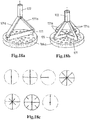
- the mass feed member comprises a funnel body that delimits the single chamber for the mass in the mass feed member.
- the funnel body has main walls of substantially triangular shape that are connected along their sides, with a mouth side thereof formed by a wall containing the mouth and with the inlet to the chamber being arranged at an apex of said main walls that is located opposite said wall containing said mouth. Due to this funnel shape the effective cross section of the chamber increases from the inlet towards the opposite side wall containing the outflow mouth.
- the mass feed member may have a single slot mouth that spans the length of the drum surface provided with mould cavities, so that all said cavities pass along said single slot.
- the chamber of the mass feed member is a closed chamber that allows for pressure of the mass during the method at a level or levels above atmospheric pressure, with the mouth being the only outlet for the mass from the chamber.
- the closed chamber also shields the mass from the atmosphere, e.g. to avoid inclusion of air into the mass, as it only has the inlet that is connected to the pump and the mouth that is directly adjacent the mobile mould member, e.g. the outer surface of the revolving drum.
- the mass feed member is provided with a straight slot that is arranged parallel to the longitudinal axis of the drum.
- One or more orificed mouth bodies and/or units as disclosed herein are arranged in the slot, e.g. releasably secured therein allowing for exchange.
- the mould drum devices are predominantly chosen for their high capacity. This capacity can amongst others be enhanced by increasing the length of the drum so as to mould more food products with a single drum. This is seen as beneficial for large capacity food producing installations, e.g. as the moulded food products may be received on a conveyor of significant width, e.g. of 0.8 or 1.0 meter that passes into a further treatment device, e.g. into an oven or a fryer.
- the method according to the invention may include the step of conveying the formed products to an oven or fryer, and subjecting the products therein to an oven treatment or frying the product.
- each mass feed member has a chamber therein for the mass that is separated from the chamber of the other mass feed member, possibly with a first and a second pump respectively connected to the first and second mass feed member, or, with multiple mass feed members connected to the same pump.
- the installation may have a single mould drum with a first section of the drum surface passing along the first mass feed member and a second section passing along the second mass feed member during revolution of the drum.
- the mould cavities of said single drum are filled by said first and second mass feed members, wherein each of the first section and the second section of the drum surface have multiple mould cavities that are arranged in a mould cavities pattern for each drum surface section with cavities at multiple (at least two, e.g. four or more) longitudinal positions when seen in longitudinal direction of the drum and at multiple circumferential position when seen in circumferential position of the drum.
- the mould cavity pattern is composed of mould cavities of identical dimensions, e.g. to mould meat patties with circular contour.
- the installation may comprise as mobile grinder member a rotary grinder member, but the provision of a reciprocal grinder member, e.g. instead of a rotary grinder member as explained herein, is also envisaged.
- the present invention also relates to a method for moulding meat products, e.g. hamburger patties, from a pumpable ground meat mass, wherein use is made of a moulding installation for moulding meat products from a pumpable ground meat mass.
- the present invention also relates to an installation having a computer control for the drum rotation, operation of the pump, and grinder operation, said control e.g. being programmed to perform the inventive methods, e.g. with a memory containing predetermined routines that make the installation perform the inventive methods for selected foodstuff masses and products to be formed.
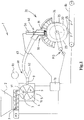
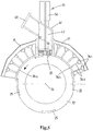
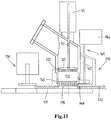
- Figure 1 schematically depicts a high capacity installation for the moulding of three dimensional products from a mass of pumpable foodstuff material, for example from a ground meat mass, e.g. for the production of hamburger patties.
- a batch of ground meat mass e.g. of beef, pork, or poultry meat, is commonly prepared in a primary grinding process (not shown) with a primary meat grinding device.
- a batch of ground meat is then e.g. loaded into a (wheeled) bin and - possibly after some storage time in a cold storage - transported to the installation as shown in figure 1 .
- the installation 1 may comprise a hopper 2 that is adapted to receive one or more batches of the mass of pumpable foodstuff material, e.g. ground meat.
- an optional feeder assembly 3 is associated with the hopper 1 to assist in discharging the mass from the hopper 2.
- one or more motor driven augers 3 with motor M3 are mounted at the bottom of the hopper 2.
- the loading of the installation may be conducted via a pipe connecting to the installation, e.g. to a hopper thereof.
- the installation further comprises a pump 5, e.g. a vane pump, a screw pump, a piston pump, etc.
- the pump 5 has a pump housing 6 with an inlet 7 receiving the mass from the hopper 2, here via the auger 3.
- the pump housing 6 further has an outlet 8 for outputting the mass.
- the pump 5 shown is a vane pump with a rotor having multiples vanes 9 disposed in a pump cavity of a pump housing.
- Such rotor pumps e.g. supplied by Risco (Italy), are known for pumping ground meat and other pumpable foodstuff masses.
- a pump drive motor (e.g. electric, shown at MP in figure 2 ) is provided for driving the pump.
- the pump 5 forms pump chambers 10, in the figure shown between neighbouring vanes 9, that each are successively in communication with the pump inlet 6 for the introduction of mass into the pump chamber and with the pump outlet 7 for the discharge of mass from the pump chamber.
- the effective volume of the pump chamber reduces from the position thereof at the pump inlet to the position thereof at the pump outlet, so that the mass is effectively expelled from the pump chamber when the pump is in operation.
- An example of such a pump is disclosed in US4761121 .
- the pump 5 may instead of a vane pump also be embodied as a different type of pump, e.g. as a piston pump having one or more reciprocating pistons.
- the installation 1 further comprises a moulding device 20 comprising:
- the drum 22 is embodied to rotate or revolve as the drum 22 is rotatably supported by the frame 21, e.g. on a cantilevered (horizontal) shaft of the frame of the device 20.
- the mould drum 22 has an outer circumferential drum surface 23 and a longitudinal drum rotation axis 24.
- the drum 22 is rotatably supported by the frame 21 to revolve about the drum rotation axis, here - as is preferred - a horizontal axis.
- the mould drum 22 has in the drum surface 23 multiple mould cavities 25, each cavity 25 having a filling opening in the plane of the surface 23 for the introduction of foodstuff mass into the mould cavity and for the later removal or release of the product from the cavity 25.
- the cavities 25 are embodied as individual recesses in the outer surface 23 of the drum body, having a bottom opposite the filling opening of the cavity 25.
- the device 20 and drum 22 are designed to allow for an easy exchange of one drum for another drum having a different pattern and shape of mould cavities so as to allow the production of different food products with the installation.
- the mould member drive MD is adapted to move the mould member along a path, here a circular part about the axis 24.
- the path includes a fill position for filling the mass into a mould cavity at mass feed member 30 that is arranged stationary at said fill position and a product release position for releasing a moulded product from the mould cavity, here at or near the lower section of the circular path.
- the formed products P are delivered onto conveyor 80 that extends below the drum 22.
- the ejection of a product from a mould cavity may be facilitated/performed by means of the cavity being bounded by porous material wall parts through which pressurized gas, e.g. air, is expelled to release the product from the cavity.
- pressurized gas e.g. air
- the cavity could also be embodied to comprise a piston type bottom as is also known in the art.
- the drum is embodied as a hollow tubular member with the cavities each being formed as an opening that extends through the wall of the tubular member.
- this moulding device comprises a bottom member that is stationary mounted in the frame and opposite from the mass feed member. This bottom member forms a bottom of the cavity opposite the filling opening of the cavity.
- the ejection of a formed product may e.g. be done by a mechanical knock-out member that knocks the formed product out of the cavity.
- the mould member drive MD is preferably an electric drive allowing for a variable and controllable drum rotation speed.
- the drum 22 is driven in a continuous, non-interrupted manner, so without starting and stopping during a revolution of the drum 22 in order to achieve a high production capacity. It is preferred that the drum 22 is driven at a constant speed during normal production (e.g. with an acceleration when starting production). It may also be that the speed of the drum 22 is periodically varied during a revolution of the drum, yet preferably without stopping and starting.
- the mass feed member 30 is adapted to transfer the foodstuff mass into a mould cavity of the mould member in a corresponding mould cavity filling event that is defined by the moment of first flow of foodstuff mass into the mould cavity 25 and the moment wherein the mould cavity has been fully filled and flow of foodstuff mass therein is terminated.
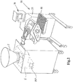
- the mass feed member 30 comprises:
- the slot 32 has a length that corresponds substantially to the axial length of the drum 22.
- Each unit 40 of the mass feed member 30 comprises a housing 41 having a chamber 42 with an inlet 43 for foodstuff mass.
- the mass feed member, here each unit 40 thereof, also has a mouth 44 at the other end of the chamber 42, which mouth faces the mould member, here the drum 22, so that mass is transferred from the chamber 42 via said mouth 44 into a passing mould cavity 25.
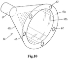
- a foodstuff mass distributor 60 is arranged between the outlet 8 of the pump 5 and the inlets 43 of these units 40. This distributor 60 splits the flow of foodstuff mass into subflows to each of the units.
- the distributor as shown has a singular inlet 61 connected or connectable to the pump 5 and a series of outlet openings 62 each connected or connectable to a respective unit 40, here via a hose 63.
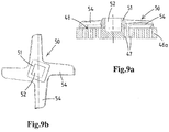
- Each unit 40 is provided with a grinder device that is adapted to subject the foodstuff mass to a grinding action.
- the grinder device comprises:
- the grinding face 48 is directed away from the mould drum 22 and the mouth body has an outlet face 49 that faces the mould member 22.
- the mass feed member 30, here each unit 40 thereof, has a grinder drive 55 that is adapted to move the mobile grinder member 50 of each of the units 40.
- each unit is provided with its own grinder drive comprising an electrical motor 56, here driving a rotary drive shaft 57.
- the motor 56 is mounted to the housing of the unit 40 so as to be exchangeable along with the unit 40.
- the mobile grinder member is a rotary cutter 50, here having a central hub 51 with an opening 52 for a drive shaft 57 and having multiple cutter blades 54. This is an embodiment that is well known in the art of meat grinding.
- FIGS 1 and 2 also illustrate the presence of a grinder device controller 70, here integrated into a computerized controller 70 of several functional components of the installation, in this example for operation of the motor M3 of the auger(s) 3, the motor MP of the pump 5, the motor MD of the drum drive, and of the product conveyor 80.
- the controller 70 allows the control the operation of each grinder drive 55 of the units 40, as is preferred such that each grinder drive is independently controllable.
- each electric motor 56 is connected to the controller 70
- the composite orificed body with parts 46a, 46b - as is preferred - comprises a metal or ceramic orificed grinder body part 46a that forms the grinding face 48 of the grinder body and a plastic mouth body part 46b that adjoins the orificed grinder body part 46a so that said orifices 47b therein form a continuation of orifices 47a.
- the plastic body part 46b forms the outlet face 49 of the grinder body that faces the mobile mould member 22. This is for example advantageous when the mould member, here drum 22, has a metal surface or metal surface parts engaging the outlet face 49 of the body.
- each unit 40 here is thus formed by a multitude of outlet orifices 47b so that each cavity 25 is filled via multiple outlet orifices 47b, e.g. cylindrical bores at various angles to obtain a desired inflow of the mass into a mould cavity 25.
- outlet orifices 47b e.g. cylindrical bores at various angles to obtain a desired inflow of the mass into a mould cavity 25.
- Other cross-sectional shapes of the outlet orifices 47b are also possible.
- the rotation of the drum 22 causes at some point in time that the mould cavity 25 overlaps with the outlet face 49 of the grinder body and the mouth thereof such that a variable effective outflow area of the orifices 47 in the orificed grinder body is afforded by the overlap.
- this effective outflow opening the ground mass can flow into the mould cavity.
- this variable effective outflow area will have a maximum, as can be determined by geometrical analysis of the mouth and the cavity.
- the installation 1 is operated such that the first flow of mass into the mould cavity 25 takes place only after a timed delay relative to the initial moment of communication between the outlet orifices 47b and the mould cavity.
- This delay of the start of effectively filling the mould cavity, so of the filling event has the advantage that the filling of the mould cavity does not start at the very leading end of the mould cavity, which normally entails a rush of the mass from said one location into the rest of the mould cavity. It has been found that this prior art inflow through the cavity causes an orientation of fibrous components of the mass, which then later, e.g. after cooking or frying a ground beef meat patty, causes the shape of the product to be distorted relative to the formed shape.
- the cavity is filled not from the leading end, but more or less over its entire filling opening in one instant. This allows to avoid the undesirable orientation of fibrous components as in the prior art approach.
- the delay can be done is several ways as will be explained herein.
- the grinder device controller is operated to cause intermittent operation of each of the grinder devices 45.
- This intermittent grinder device operation is synchronized with the movement of the mould member 22, such that the foodstuff mass is subjected to the grinding process during the filling event as the grinder drive drives the mobile grinder member 50 at a grinding speed during the filling event and such that in an intermediate period between successive filling events the grinder device 45 is halted or operated at a slower speed relative to the grinding speed, preferably halted.
- the grinder device controller is operated to cause intermittent operation of each of the grinder devices 45.
- the filling events taking place at one unit 40 or position of the mass feed member can succeed one another at a very high pace, e.g. each 0.5 seconds or even each 0.25 seconds a new filling event.
- This means in practice that the intermediate period between filling events can have a duration between, for example, 0.1 and 0.3 seconds. It is in this intermediate period that the grinder device 45 in said unit is at a standstill or operating slowly. The actual grinding by the device 45 and then performed in periods that may e.g. last between 0.1 and 0.4 seconds.
- the grinder device is preferably adapted to operate the mobile grinder per filling event such that the mobile grinder member passes over each orifice in the orificed grinder body at least twice. This will require a high operating speed, e.g. rotational speed or reciprocal frequency of the mobile grinder member. These speeds are possible with existing grinder equipment.
- the mass feed member e.g. each unit 40, is provided with a stator member adjacent the mobile grinder member, the stator member being designed to restrain the mass from moving along with the mobile grinder member.
- the stator member includes one or more panels with their planes in flow direction of the mass towards the mouth.
- moulding devices wherein a mould plate with mould cavities (e.g. in one or two parallel rows) is reciprocated between a filling position at the mass feed member and a remote knock-out position.
- mould plate with mould cavities e.g. in one or two parallel rows
- These devices commonly operate at a slower pace, e.g. with filling events every 0.6 to 4.0 seconds, than drum moulding devices.
- composition of the foodstuff mass that is pumped by the pump 5 into the chambers 42 of the units 40 of the mass feed member 30 is such in relation to the orifices 47a,b that the foodstuff mass in said through-the-pump-composition is unable to pass through the effective outflow area of the orifices 47a,b under influence of the foodstuff mass pressure in the chambers of these units.
- the primary grinding of meat supplied to the hopper 2 has been done such that the meat mass is very coarse, with meat particles too big to pass through the orifices under the influence of the pressure in the chamber 42.
- each of the grinder devices 45 causes a change in said foodstuff mass composition, it is ground to a finer composition, so that the foodstuff mass does pass through the effective outflow area of the orifices in the orificed grinder body.
- the start of the operation of the grinder device 45 then triggers the first flow of mass into the mold cavity and thus the start of the filling event of a mould cavity. So the grinder device functions as a sort of controller by means of the grinder device being in operation or being halted or operated slowly.
- the pressure of the mass in the chamber 42 of each unit also affects the inflow of mass into the mould cavity.
- This pressure can, in an embodiment of operation of the installation, be kept at a substantial constant pressure level during operation of the installation. It is however also envisaged to effect a periodically varying pump rate by suitable control of the pump in timed relation to the motion of the mould member, so that the pressure in the chamber 42 is used as a further parameter to steer the actual flow of mass into the mould cavity.
- the composition of the foodstuff mass that is pumped by the pump into the mass feed member chambers 42 is such in relation to the orifices 47a,b that the foodstuff mass in said composition is unable to pass through the effective outflow area of the orifices in the orificed grinder body under influence of foodstuff mass pressure in the chamber of said mass feed member.
- the orifices then form a flow resistance that is too great for the mass to overcome, e.g. with the mass being so coarse that it will only flow through the orifices if the pressure would be significantly greater. It is then possible to operate the grinder devices, changing the mass into a finer ground mass that is able to pass through the orifices and thus starting the filling event.
- the operation of the pump drive is controlled so as to vary the foodstuff mass pressure in the chamber of the mass feed member between a lower pressure at which said foodstuff mass does not flow through said effective outflow area and a raised pressure at which said foodstuff mass does flow through said effective outflow area, so that the operation of the pump is employed to trigger the first flow of mass into the mould cavity and thus the start of the filling event.
- a valve e.g. a sliding plate valve
- the mass feed member e.g. a valve in each unit 40.
- the opening of the valve is employed to trigger the first flow of mass into the mould cavity and thus the start of the filling event.
- the valve is a plate lying against the orificed grinder body and having openings in the plate corresponding to the orifices in the grinder body, so that in one position the openings and orifices are aligned and thus the valve opened and in another position the openings are not aligned with the orifices, so that the valve is effectively closed.
- the grinder devices 45 may be employed to effectively subject to the mass to a secondary grinding process very shortly before the mass enters the cavity 25 and is formed into the desired shape. This approach allows the primary grinding to be relatively coarse in view of the finally desired characteristics of the formed product, with the secondary grinding resulting in the final product characteristics.
- the method may include the use of a primary grinder performing the primary grinding process, which has an orificed grinder body with a multitude of smallest primary grinding orifices therein, which smallest primary grinding orifices are of greater diameter than the smallest orifices in the grinder device at the mouth of the mass feed member subjecting the mass to the secondary grinder process, for example at least 2 times greater in diameter, preferably at least 3 times greater.
- the primary grinder as is common in the art, may have multiple grinder bodies in series, with the final grinder body having the smallest primary grinding orifices.
- the mass feed member may be equipped with one or more "dual-phase" or "multi-phase” grinder devices, so with multiple grinder bodies in series.
- the orifices in the grinder devices 45 of the mass feed member have a diameter between 2 and 12 millimetres, e.g. between 2 and 6 millimeters, e.g. between 2 and 4 millimeters.
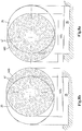
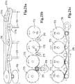
- the drum 22 is provided with a pattern of multiple mould cavities 25 with cavities 25 at distinct perpendicular axis positions when seen perpendicular to the path of the mould member, so here at different positions relative to the length of the drum 22.
- the drum 22 as is a common embodiment in the art, is provided with arrays of multiple cavities 25 when seen in circumferential direction of the drum 22, with axial spacing between adjacent arrays when seen in axial direction of the drum.
- cavities in adjacent arrays on the drum 22 are aligned in rows that are parallel to the axis 24. It is however preferred in view of the mass pressure in the mass feed member chambers 42 to have the cavities in non-parallel arrangement, e.g. staggered when seen in longitudinal direction on the drum or in spiralling lines.
- the mould cavities in one array are offset - in the direction of the path of movement of the mould member - relative to the mould cavities in one or more, preferably all, other arrays, so that the start of the filling events of the mould cavities of said one array is at a different moment than the start of the filling event of said one or more offset arrays of mould cavities.
- a non-parallel arrangement has the advantage that filling events do not take place per parallel row but are more distributed in time. This is beneficial, e.g. in view of control of mass pressure in the mass feed member chambers 42 and in view of pump operation.
- each mobile grinder member 50 has an associated independently controllable grinder drive 55 allowing to independently operate each mobile grinder member 45.
- the same is however also possible in combination with a single row or parallel row mould member, e.g. to enable a different grinding process of the foodstuff entering some mould cavities of the row compared to foodstuff mass entering some other mould cavities.
- the mass feed member may be provided with multiple mobile grinder members at the distinct perpendicular axis positions when seen perpendicular to the path of the mould member, these positions of the mobile grinder members each corresponding to the perpendicular axis position of a mould cavity, preferably the mobile grinder members being exchangeable, so that the flow of foodstuff mass into a mould cavity at a respective perpendicular axis position is ground by a respective mobile grinder member.
- the duration of a filling event lies between 25 milliseconds and 500 milliseconds, e.g. between 50 and 200 milliseconds.
- the mould member e.g. the drum 22
- the mass feed member comprises a main carrier member supporting the units 40, wherein the housings 41 of the units 42 are releasably secured to the main carrier member, so as to allow for exchange of each of said multiple units, preferably such that each unit can be independently exchanged without release of any other unit 40.
- This allows to use units 40 that are tailored to the product to be made with the respective mould member.
- the mass feed member comprises a main carrier member supporting said multiple units, wherein the housing of one or more, preferably all, of the multiple units is secured to the main carrier such as to allow for variation of the position of said one or more units in the direction of said perpendicular axis.
- the exemplary distributor 60 has a distributor housing forming a conical chamber between a conical outer chamber wall 60a and a conical inner chamber wall 60b, so as to form the singular inlet 61 at the apex of the conical chamber, and with an annular rear wall 60c at the outlet side of the conical chamber, wherein the series of outlet openings 62 is formed in the annular rear wall 60c.
- the grinder device controller 70 is configured, e.g. programmed, to start the grinding process by bringing the mobile grinder 50 to the grinding speed after the effective cross-sectional outflow area of the orifices in the orificed grinder body afforded by overlap between said orifices and a mould cavity has reached a predetermined lower limit.
- mass feed member 30 sealingly engages the surface 23 of the drum 22 in which the cavities 25 are formed, so that substantially no mass may escape between the mass feed member and the mould drum.
- the mass feed member 30 is integrated with a closure member 34a that extends in downstream direction from the mouth 44 of the mass feed member to keep the filled cavities 25 closed for a while as the filled cavities move away from the fill position. This allows the mass to become a more coherent food product.
- the mass in the mould cavity forms the food product, e.g. the meat patty.
- a closure member 34b is preferably provided to also extend from the mouth 44 in upstream direction, in order to closure the cavity as it is in communication with the mouth 44.
- mould drum 22, mass feed member 30, and closure member 34 are e.g. disclosed in WO00/30548 and in WO2004/002229 .
- the one or more closure members 34a, b may each comprise a semi-circular plate member, preferably of flexible design, that is urged in sealing contact with the surface 23 by one or more actuators, e.g. pneumatic actuators 34c, e.g. with transverse lamellae 34d between the plate member and the one or more actuators.
- actuators e.g. pneumatic actuators 34c, e.g. with transverse lamellae 34d between the plate member and the one or more actuators.
- the pump 5 urges the foodstuff mass through the tubes or hoses 63 towards the units 42 of the mass feed member 30.
- suitable control of the pump 5, e.g. of the pump rotor speed, e.g. using a controllable electric pump drive motor MP the output of mass by the pump and thereby the pressure of the mass in the chambers 42 can be controlled.
- this pressure control may include the sensing of the actual pressure of the mass in the chambers 42 by a pressure sensor, said signal acting as a feedback signal for a pump control unit.
- the formed product P here meat product P
- the mould cavity 25 e.g. to be transported onward on a conveyor 80, e.g. to other downstream equipment, e.g. an oven, a fryer, etc.
- the installation may comprise a controllable vacuum assembly 90, e.g. integrated with the pump 5 as is known in the art.
- This vacuum assembly 90 is adapted to cause controlled evacuation of air from the mass at one or more locations in the trajectory of the mass from the hopper 1 to and including the pump chamber at a position where it is in communication with the pump inlet 6 of the positive displacement pump.
- this vacuum assembly comprises a vacuum pump, e.g. an electrically operated vacuum pump.
- a vacuum port 91 is arranged in the pump 5 so as to be effective in establishing a vacuum in the pump chamber that is in communication with the inlet 6 during operation of the pump 5. This vacuum assists in the complete filling of the pump chamber with a portion of the mass.
- a vacuum may be created in the hopper 1 as is known in the art.
- a vacuum may also be created in any passage between the hopper 1 and the pump inlet 6, e.g. in a duct into which one or more augers 3 of a feed assembly extend.
- a vacuum assembly 90 allows the evacuation of the foodstuff mass, e.g. the ground meat mass, so as to reduce the presence of air in the mass. This e.g. increases the uniformity of the products when it comes to the weight of mass that is effectively introduced into each of the mould cavities, among other advantages.
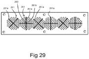
- the drum 22 is provided with multiple mould cavities 25 which are arranged in the drum surface 23 in a mould cavities pattern with cavities at multiple (possibly two, preferably four or more) longitudinal positions when seen in longitudinal direction of the drum 22 and at multiple circumferential positions when seen in circumferential position of the drum 22. So in general terms a 2-dimensional pattern of cavities in the surface 23 of the drum 22.
- the installation comprises a foodstuff mass pressure sensor adapted to sense pressure of the foodstuff mass in the chamber or chambers 42 of the mass feed member, and wherein the installation comprises a pump control unit 70 connected to the foodstuff mass pressure sensor.
- a pump controller allows to select a target pressure or target pressure range for the foodstuff mass in the chamber, wherein the pump controller is configured, e.g. programmed, to stop or slow the pump when the measured foodstuff pressure exceeds said target pressure or said target pressure range and wherein the pump controller activates or accelerates the pump when the measured foodstuff pressure drops below said target pressure or target pressure range.
- the installation is provided with a pump timing mechanism that causes activation or acceleration of the pump 5 during intervals that take place periodically, e.g. during a revolution of a mould drum 22, each of said intervals being in timed relation to a corresponding filling event of a single mould cavity, an interval at least partly being in timed overlap with said single filling event, said activation or acceleration causing a temporary increase of flow of foodstuff mass to the mass feed member 15 during said interval and said flow being relatively reduced in between successive intervals.
- the installation comprises a position-determining device, e.g.
- a position sensor for determining and/or detecting the position of a mould cavity relative to a mouth of the mass feed member during motion of the mould member, said position-determining device being linked to the grinder controller so as to provide an input signal for the operation of the grinder device or devices 45.
- the mobile grinder member is mobile, e.g. rotated or reciprocated, (at high speed), but also the orificed grinder body is movably mounted, e.g. reciprocable in perpendicular axis direction.
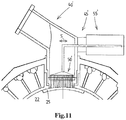
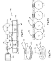
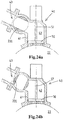
- FIG 11 depicts an alternative embodiment of a grinder device, here integrated in a unit 40'.
- the mobile grinder member 50' is embodied as reciprocating grinder member, as indicated by arrow S in the figure. Due to its reciprocating motion by drive 55' over the grinding face 48 of the orificed grinder body the mass is effectively grinded if the device 45' is in operation.
- a corresponding mobile grinder member 50' is provided, preferably driven by an associated independent drive 55', preferably in a path parallel to the path of motion of the mould member, here the drum 22. So if e.g. five arrays of mould cavities are present, the mass feed member may be provided with five independently driven mobile grinder members.
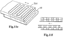
- Figures 11a - f illustrate possible embodiments of the reciprocating grinder member 50'.
- the member 50' is provided with a series of parallel grinder blades 50b having a sharp edge.
- the blades 50b are mounted in a frame 50b and extend at right angles to the grinding face 48 so as to not hinder the mass flow in an undesirable manner.
- the spacing between adjacent blades 50b corresponds to the spacing between adjacent orifices in the grinder body so that the stroke can be small.
- the member 50' is embodied as an orificed plate 50c that is reciprocated between a position wherein the orifices in the plate 50c align with the orifices in the grinder body below, and a non-aligned position as is shown in figure 11d .
- the orificed plate 50d is provided with slotted orifices instead of cylindrical orifices.
- the same slotted orifices are present in the grinder body which mates with the plate 50d.
- the operation is shown in figure 11f .
- the mouth can comprise all kinds of combinations of shapes of orifices which lead the mass into the mould cavities, e.g. slotted and cylindrical orifices combined in a group to form the outlet mouth that transfers mass into cavities in an array of the passing mobile mould member.
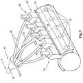
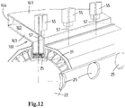
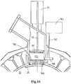
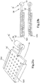
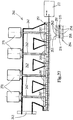
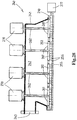
- the mass feed member 30 instead of having multiple units 40 each associated with a single circumferential array of mould cavities on the drum 22, the mass feed member now comprises a manifold body 100 delimiting a single elongated chamber 102 of the mass feed member, here the manifold body having a length corresponding to the length of the drum so as to transfer mass into all arrays of the drum.
- the manifold body In an alternative embodiment two such manifold bodies are provided, each covering half the length of the drum 22 (or plate in a plate moulding device).
- the manifold body 100 has main walls 103 of substantially triangular shape connected along a mouth side thereof by a wall containing the mouth, e.g. the mouth embodied with spaced apart regions of multiple orifices, each region being aligned with an associated circumferential array of mould cavities.
- the manifold body has an inlet 104 arranged at an apex of the main walls 103 that is located opposite said wall containing said mouth, such that the effective cross section of the chamber increases from said inlet 104 towards said wall containing the mouth.
- each shaft 57 is driven by a separate motor, but in another embodiment the shafts 57 are e.g. connected to a common drive motor, e.g. via a belt or gear transmission.
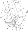
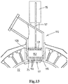
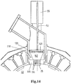
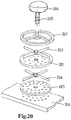
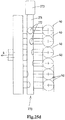
- Figure 13 illustrates a mass feed member 110 wherein the mouth 111 is formed by an orificed mouth body 115 that has a multitude of orifices 116 therein through which the mass is transferred into the mould cavity 25 of the mould member 22.
- the mass feed member 110 has a grinder device with an orificed grinder body 120 and a cooperating grinder member 121, preferably the grinder body being stationary mounted in the chamber 112 of the mass feed member and the grinder member 121 being movable.
- the grinder member 121 is a rotary grinder member.
- the grinder body and grinder member are spaced from the orificed mouth body 121, so that a buffer space of the chamber 112 is present between the actual grinder and the mouth body 121, in which buffer space mass is stored that has been ground by the grinder.
- This design e.g. allows for a difference between the arrangement of orifices in the grinder body on the one hand, and the orifices in the mouth body 121 on the other hand. It e.g. allows to use a single design of a grinder body in combination with a set of multiple mouth bodies that have different arrangements of the orifices therein, e.g. tailored to the products to be moulded.
- the method then includes the step of selecting a mouth body from said set, and mounting said selected mouth body in the mass feed member.
- the buffer space 112 preferably has a rather limited volume, e.g. corresponding to between one time and five times the volume of the mould cavity 25 to be filled from the buffer space. This allows for some residence time of the ground mass, before being passed into the orifices of the mouth body. The residence time may e.g. be beneficial in view of cohesion of the foodstuff mass.
- a further use of the buffer space 112 may be to accommodate therein stacked layers of foodstuff mass, wherein the layers differ with respect to the grinding of the mass.
- the mass fed to the mass feed member is sufficiently fine to pass through the orifices of the grinder body and the mouth (e.g. orificed mouth) under the influence of the mass pressure exerted by the pump. Then it depends on the operation of the grinder, whether or not mass passing through the grinder body is effectively ground.
- a mixer is present, e.g. a static mixer, so that a mix of mass that is ground with mass that has not been ground by the grinder of the mass feed member is obtained.
- the orificed mouth body is exchangeable for another orificed mouth body, primarily to tailor the mouth body to the mould cavities in the drum.
- the drum (or other mould member) in figure 14 has smaller diameter mould cavities than the figure 13 embodiment.
- the group of orifices in the mouth body is altered accordingly by replacing the mouth body.
- the figure 14 also illustrates the feature to provide a funnel member 118 between the orificed mouth body on the one hand and the spaced apart grinder body on the other hand, with the funnel member 118 having a tapering passage therein that is dimensioned at one end according to the group of orifices in the grinder body and on the opposed end to the group of orifices in the mouth body.
- the figure 15 illustrates a moulding device 130 not having a mould drum but a mould plate 132 as is another well-known food product moulding device type.
- the moulding device has a frame 131 movably supporting a reciprocating mould plate 132 that is reciprocated in its plane by means of a drive. Many examples are known in the art.
- the mould plate 132 has a row of mould cavities 135 that extend through the thickness of the mould plate, so are open at opposed ends.
- the row of cavities 135 extends perpendicular to the direction of motion of the plate.
- the figure 15 shows the cavity at the filling position. There the mould cavity is, as is preferred for this type of device, at a standstill during a dwell time, after which the plate is moved to bring the mould cavity to a release or knock-out position underneath knock-out device 136.
- Figure 15 illustrates the possibility to arrange, preferably at each of the multiple distinct perpendicular axis positions as explained herein, an orificed mouth body 140 with a multitude of orifices therein, wherein the body 140 is mounted in the mass feed member in a rotatable manner, e.g. circular at its outer circumference and journalled in a main carrier body of the mass feed member.
- a mouth body rotary drive 145 is provided, here with a motor 146, drive shaft 147 and gear transmission 148 to be able to rotate the mouth body. It is envisaged that during a filling event, the mouth body is rotated over less than a full revolution, e.g. over less than half a revolution, e.g. over about a quarter revolution. This may be done to obtain a desired inflow of mass into the mould cavity.
- the orificed mouth body 140 does not cooperate with a grinder member, no further grinding is effected by this limited angle rotation.
- Figure 16 illustrates the provision of a valve member 150 at the entry side of the orificed mouth body 140, here, by way of example in a mould drum device.
- the valve member 150 is used in this example as trigger for the start of a filling event, e.g. as the composition of the mass in combination with the mass pressure in the chamber of the mass feed member is such that the mass will flow through the orifices in the mouth body when the valve member is opened.
- valve member 150 is an orificed body as well, which is mounted rotatably, with the mouth body 140 being stationary so that in one position the orifices in the valve member 150 are aligned with the orifices in the mouth member and in another, closed, position the orifices are misaligned so that the valve is effectively closed.
- valve member 150 could also serve as orificed grinder body with the grinder member 121 cooperating directly with the grinding face formed by the valve member 150.
- the figures 17a, b, c illustrate an alternative embodiment of the mass feed member.
- the mass feed member 160 has a manifold body 161 delimiting a single elongated chamber 162 of the mass feed member, here the manifold body having a length corresponding to the length of the drum (not shown) so as to transfer mass into all arrays of cavities of the drum.
- two such manifold bodies are provided, each covering half the length of the drum (or plate in a plate moulding device).
- the manifold body 161 has an inlet 163, here located opposite the mouth of the mass feed member.
- the mass feed member has an orificed grinder body comprising a metal orificed grinder body 164 that forms the grinding face and that is stacked on a plastic orificed grinder body 165 that faces drum.
- the mass feed member 160 is provided with multiple grinder devices 170 along the length of the chamber 162, here each comprising a rotary grinder member 171 driven by shaft 172.
- each shaft 172 extends out of the chamber 162 and that the protruding part of the shaft 172 is provided with a pinion 173 that meshes with a worm gear 174 on a rotary shaft 175 driven by motor 176.
- multiple grinder devices 170 are driven by said common shaft 175 and motor 176.
- the grinder body 164 can be an elongated plate body having the length of the chamber 162 as shown in figure 17a , but, as is shown in figure 17b , it is also envisaged that for each rotary grinder member 171 there is a corresponding metal orificed grinder body 164a which is e.g. received in an apertured mounting plate with multiple apertures for such grinder bodies 164a.
- the figures 18a and 18b illustrate alternative grinder devices wherein the drive shaft 172 terminates at a distance from the orificed grinder body 164a, and wherein the actual grinding part of the rotary grinder member 171 is connected to the free end of the drive shaft 172 via multiple legs 171a of said member 171, here each from an outer end of a grinder member leg 171a inclined towards the central drive shaft end.
- This open structure of the rotary grinder member allows for a rather unhindered passage of the mass towards the orificed grinder body 164a.
- the figure 18c illustrates various forms of the rotary grinder member 171.
- the figures 19a , b, c illustrate yet another alternative embodiment of the mass feed member.
- the mass feed member 180 has a manifold body 181 delimiting a single elongated chamber 182 of the mass feed member, here the manifold body having a length corresponding to the length of the drum (not shown) so as to transfer mass into all arrays of cavities of the drum.
- two such manifold bodies are provided, each covering half the length of the drum (or plate in a plate moulding device).
- the manifold body 181 has an inlet 183, here located at an axial end of the manifold 181.
- the mass feed member has an orificed grinder body comprising a metal orificed grinder body 184 that forms the grinding face and that is stacked on a plastic orificed grinder body 185 that faces drum.
- the mass feed member 180 is provided with multiple grinder devices 190 along the length of the chamber 182, here each comprising a rotary grinder member 191 driven by shaft 192.
- each shaft 192 extends out of the chamber 182 and that the protruding part of the shaft 192 is provided with a pinion 193 that meshes with the pinion of an adjacent grinder 190.
- One of the pinions 193 is fitted on a shaft 192 that is driven by motor 196, so that multiple grinder devices 190 are driven by said single motor 196.
- the pinions 193 are present in a gear case 195 of the mass feed member.
- the figures 19b, c illustrate that the metal orificed grinder body 194 is provided with parallel orifices 186, preferably at right angles to the grinding face, and that at least some of the adjoining orifices in the plastic body 195 are arranged at various angular orientations in view of an optimal distribution of the inflow of mass into a mould cavity.
- a central group of orifices 187 in body 195 is directed at an inward angle to provide an outlet in the outlet face below the end of the drive shaft 192.
- Another group 188 along the outer perimeter of the group of orifices in the body 195 is outwardly inclined so as to allow flow into a cavity near the perimeter of the cavity.
- Figure 19c shows the outlet face formed by the body 195 with multiple groups of orifices having an outlet in said face, each group corresponding to an array of passing mould cavities in the mobile mould member, e.g. drum.
- Figure 20 illustrates an embodiment of a mass feed member grinder device 200 of the "dual phase type".
- multiple orificed grinder bodies are placed in series, with the final orificed grinder body having the smallest orifices.
- a first grinder body 201 has a grinding face along which first rotary grinder member 202 passes.
- a second orificed grinder body 203 is present and a second rotary grinder member 204 is arranged between the bodies 201 and 203.
- This member 204 cooperates with the grinding face of the second body 203.
- the members 202 and 204 are driven by common rotary drive shaft 205 and motor 206.
- a bearing bracket 207 may be provided as intermediate support of the drive shaft in the chamber.
- the orifices in the second or final body 203 have a smaller diameter than the orifices in the first body 201.
- the final body 203 lies against a plastic orificed body 206 as explained with reference to other alternatives for the grinder device.
- mass feed member may be equipped with one or more “dual-phase” or “multi-phase” grinder devices, so with multiple grinder bodies in series.
- Figures 21a, b, c illustrate alternative embodiment of the transmission between a single grinders drive motor 176 and multiple grinder devices each having a rotary drive shaft 171.
- the motor 176 drives a common belt or chain 210 which engages, e.g. meshes, a transmission member 171b on the shaft 171, e.g. a pinion.
- a transmission member 171b on the shaft 171 e.g. a pinion.
- each of the shafts 171 is provided with a pinion 173 and intermediate gears 211 are placed between adjacent pinions 173, e.g. to cause the effect that all shafts 171 rotate in the same direction.
- the motor 176 drives this transmission train, e.g. by driving one of the intermediate gears 211 as shown here with a further chain transmission.
- FIG 21c an alternative common belt 210 is shown to drive all shafts 171via a respective pinion 173 fitted on the shaft 171.
- the figure 22a illustrates a reciprocating drive arrangement for driving a reciprocating grinder member 50" of a grinder device in a mass feed member.
- a reciprocating grinder member 50" for all circumferential arrays of mould cavities on a drum (in this example four arrays, drum not shown) a common reciprocating grinder member 50" is provided.
- the member 50" is reciprocated in a direction that is parallel or tangent to the path of motion of the drum, so at right angles to the longitudinal axis of the drum.
- the grinder member 50" is embodied as an orificed mobile grinder member with groups of orifices therein corresponding to groups of orifices in the mating grinder body 46a similar to the embodiment explained with reference to figures 11c, d with each group corresponding to a passing array of mould cavities. It will be appreciated that member 50"as in figure 22a could also be embodied as shown in figure 11a, b or otherwise.
- the common reciprocating grinder member 50" is driven by an associated drive 55", here comprising a rotary output shaft motor 56 connected via a crank mechanism 58 to the reciprocating member 50".
- the figure 22b illustrates another reciprocating drive arrangement for driving a reciprocating grinder member of a grinder device in a mass feed member.
- the grinder member 50" is reciprocated in a direction that is parallel to the longitudinal axis of the drum (so in longitudinal direction of the mass feed member).
- the figures 23a, b illustrate a reciprocating drive arrangement for driving a reciprocating grinder member as shown in figure 11 .
- the member 50' is dimensioned to cooperate with a part of the orificed grinder body 46a having a single group of orifices that fill an array of mould cavities that pass said group of orifice in operation of the device. So per array there is an individually driven member 50' in the mass feed member with a motor 56 and a transmission, here a crank mechanism 58.
- Each member 50' is guided in guides 50d of the mass feed member (or of a unit 40) that extend transverse to the longitudinal axis of the drum (not shown).
- FIGS 24a, b illustrate the provision of a controlled valve in a unit 40, here at the inlet 43 to the chamber 42 within the housing of the unit 41.
- the valve is embodied as a ball valve 220, e.g. electrically controlled, e.g. in timed relationship to the passing of mould cavities along the mouth formed by the unit 40.
- the valve 220 can be employed to control the start of each filling event.
- the valve 220 is placed upstream of the grinder device with mobile grinder member 50, here at the inlet 43 of the unit 40.
- valve 220 could also be placed at the inlet of a mass feed manifold having a mouth that feeds multiple arrays of mould cavities, e.g. as shown in figure 12 where the valve 220, e.g. ball valve, could be arranged at the inlet 104 of manifold 103.
- valve 220 e.g. ball valve
- Figure 25a illustrates schematically a mould member, here drum, 22 with mould cavities 25 that are not aligned on a line parallel to the drum axis but are offset in circumferential direction from one array of cavities 25 to the next.
- Each unit 40 has a mouth corresponding to one array of passing cavities 25 and has a valve 220, here a ball valve at the inlet 43 of the housing of the unit.
- a distributor 60 distributes the mass emerging from the pump (not shown) to all of the inlets of the units 40.
- the valves 220 are all connected to a valve control unit that allows to time the opening and closing of each individual valve in timed relation to the passing of the respective cavities 25, e.g. allowing to control the start of the individual filling events.
- the distributor 60' is provided with a distributor valve 261 having a housing 262 with an inlet 263 connected to the pump 5 and with multiple outlets 264 connecting to tubes or hoses 63 that each lead to a corresponding unit 40.
- the valve 261 has a movable, here rotatable, valve member 265 that selectively connects to the inlet 263 to a selected outlet 264 and thus passes the mass to a selected unit 40.
- valve member actuator 266 is embodied as an electric motor.
- Figure 25d schematically depicts a distributor valve 270 that allows for a similar control of the flow of mass to each unit as with the valve 261.
- the movable valve body 271 is a rotatable shaft having multiple apertures 272, each one for controlling the flow to a corresponding unit 40.
- the actuator 273 controls the angular positioning of the shaft 271.
- Figures 26a, b illustrate the provision of a controlled valve 230 at the mouth of the chamber 42 of a unit 40 of the mass feed member.
- valve 230 is embodied with multiple parallel valve rods 231 that each intersect several orifices 232 formed in an orificed valve block 233.
- One side of the valve block 233 in this example is embodied as a grinding face that cooperates with a mobile grinder member 50 that passes over the grinding face, e.g. the valve block 233 being made of metal.
- a metal orificed grinder plate body is placed over the inlet side of the valve block, e.g. the block being made of plastic.
- valve rods 231 are made of metal.
- valve rods 231 In one angular position of the valve rods 231 the apertures 235 in the valve rod 231 align with the orifices 232 in the valve block 233, so that the valve 230 is open and foodstuff mass can pass through the orifices 232 towards the mould cavity in drum 22. In another angular position of the rods 231 the valve 230 is closed.
- all rods 231 have a pinion 234, with the pinions meshing so that all rods 231 are moved simultaneously, e.g. by a controlled electric valve drive motor.
- the one or more valve rods are movable in their axial direction for the purpose of opening and closing the valve.
- valve rods 231 of a valve corresponding to a single array of passing mould cavities are actuated simultaneously between opened and closed position.
- one set of rods is actuated in timed delay relative to another set of rods 231 of the valve 230 so that the flow of mass into a mould cavity can be further controlled.
- a valve 230 has multiple valve actuators, e.g. electric motors or solenoids, each actuating a group of one or more valve rods of the valve 230 allowing to obtain a timed variation of opening of orifices in a group of orifices relating to the filling of a mould cavity.
- the valve 230 can also be employed in a mass feed member without provision of any grinding device as disclosed herein in order to obtain a timed filling of the passing mould cavities that are to be filled with foodstuff mass.
- Figure 27 illustrates the provision of another controlled valve at the mouth of the chamber of the mass feed member.
- the mass feed member 240 has a manifold body 241 delimiting a single elongated chamber 242 of the mass feed member.
- the manifold body has a length corresponding to the length of the drum (not shown) so as to transfer mass into all arrays of cavities of the drum.
- the manifold body 241 has an inlet 243 for the mass emerging from the pump.
- the mass feed member 240 is provided with multiple grinder devices 260 along the length of the chamber 242, here each comprising a rotary grinder member 261 driven by shaft 262.
- each shaft 262 extends out of the chamber 242 and that the protruding part of the shaft 262 is driven by a motor 270.
- a common drive arrangement for the multiple grinders is also possible.
- the mass feed member 241 has an elongated a metal orificed grinder body 251 that forms the grinding face 253 that cooperates with all grinder members 261 and has orifices 252 therein.
- the mouth body further comprises an elongated plastic orificed body part 254 forming the outlet face 255 of the mouth body with the orifices 256 therein each in communication with a respective orifice 252.
- the outlet face 255 faces the drum (not shown).
- the mouth body is provided with a controlled valve therein allowing to open and close the connection between orifices 252 in the grinder body 251 and the orifices 256 in the body part 254.
- the valve comprises an orificed valve plate 275 that is placed between the body 251 and body part 254 and that is slidable in its plane between a position wherein orifices 276 in the valve plate 275 align with the orifices 252 and 256 so that the valve is open and a closed position wherein the valve plate 275 closes the connection between the orifices 252 and 256.
- the valve plate 275 is actuated by an actuator 277, e.g. a solenoid actuator.
- the valve plate 275 may be employed in view of the timing of the start filling events of a row of multiple cavities passing along the mouth of the mass feed member. As only a single valve plate is present in this example, all these events will start at the same time.
- multiple valve plates are provided in the mass feed member, each governing the opening and closing of a group of orifices relating to the filling of an array of mould cavities in the drum, e.g. with the individual operable actuator for each valve plate causing a valve plate motion at right angles to the plane of the figure 27 .
- valve plate 275 can be made of a suitable plastic material and/or a further plastic body being present between the grinder body 251 and the valve plate 275.
- valve plate 275 and grinder body 251 are integrated into a single orificed plate body 290, so that effectively a valve plate is created to open and close the orifices 256 at their inlet side and so that the combined valve plate and grinder body 290 effectively forms the grinding face 253 on the face opposite the body 254, which face 253 cooperates with one or more mobile grinder members 261, preferably with multiple rotary grinder members arranged at spaced positions along the length of the combined valve plate and grinder body 290.
- the grinder body and/or the layer thereof forming the grinder face and the one or more mobile grinder members may be made of metal or other suitable material, such as ceramic material.
- Fig. 29 shows schematically, looking at the grinding face, a grinder body and multiple rotary grinder members 261, each having one or more grinder blades 261a that extend from a hub 261b, e.g. connected to a rotary drive shaft 262. It is illustrated that the one or more grinder blades 261a of one grinder overlap the rotary path of the one or more grinder blades of an adjacent grinder, so that their effective circular grinding areas have an overlap. In other words the one or more blades 261a of one grinder mesh with the one or more blades of an adjacent grinder.
- This approach allows for a relatively dense arrangement of cavities, e.g. when the mould member is a drum mould member with spirally arranged mould cavities. Also this approach avoids or reduces the occurrence of stagnant zones in the chamber of the mass feed member caused by non-orificed regions of the grinder body.
Landscapes
- Life Sciences & Earth Sciences (AREA)
- Engineering & Computer Science (AREA)
- Wood Science & Technology (AREA)
- Zoology (AREA)
- Food Science & Technology (AREA)
- Meat, Egg Or Seafood Products (AREA)
- Manufacturing And Processing Devices For Dough (AREA)
- Formation And Processing Of Food Products (AREA)
- Processing Of Meat And Fish (AREA)
Description
- The present invention relates to installations and methods for moulding food products from a pumpable foodstuff mass. The invention is advantageously employed for the manufacture of meat products from a pumpable meat mass, e.g. a ground beef mass, for the manufacture of meat patties.
- A known method for manufacture of e.g. meat patties involves the use of an installation having a frame and a mould drum with an outer circumferential drum surface and a longitudinal drum rotation axis, often a horizontal axis. The drum is rotatably supported by the frame to revolve about the drum rotation axis. The drum has in the drum surface multiple mould cavities, each having a filling opening for the introduction of foodstuff mass, e.g. ground beef mass, into the mould cavity. A mould drum drive is coupled to the drum to drive the drum in a rotation direction. A mass feed member is stationary arranged at a fill position. This mass feed member has a single chamber with an inlet for the foodstuff mass to introduce foodstuff mass into the chamber and with a mouth facing the drum surface that is provided with the mould cavities. The mass feed member is adapted to transfer mass from the chamber into the passing mould cavities of the rotating mould drum when the filling opening of a mould cavity is in communication with the mouth at said fill position. The mass that has been filled into a mould cavity remains in said cavity for a while, commonly the installation has a closure member that extends in downstream direction from the mass feed member at the fill position and temporarily keeps the filled mould cavities closed downstream of the fill position, e.g. to allow the mass to become a more coherent food product. The mass in the mould cavity forms the food product, e.g. the meat patty. The installation comprises a pump that is connected to the inlet of the mass feed member and is adapted to feed foodstuff mass under pressure into the chamber of the mass feed member. A food products release or knock-out mechanism is provided, e.g. associated with the mould drum, and is adapted to cause or facilitate removal of the food product at a product removal position that is downstream of the fill position. It is for example known to provide air channels in the drum that extend to the cavities and allow to selectively introduce air that has been supplied from a manifold at a head end of the drum via said channels to between the drum and the product in order to facilitate the release thereof from the mould cavity. Other release or removal mechanisms, e.g. using a mechanical ejector, are also known in the art.
The production of moulded food products, e.g. meat patties, with such installations generally includes: - driving the drum in its rotation direction in a continuous, non-interrupted manner;
- operating the pump so as to feed foodstuff mass to the mass feed member and establish a foodstuff mass pressure in the chamber of said mass feed member,
- transfer of pressurized foodstuff mass via the mouth into each passing mould cavity,
- release of the moulded products from the mould cavities.
- Some small capacity prior art moulding devices of the design mentioned above have a drum of minimal axial length that is only provided with a single circumferential array of mould cavities that are arranged at different circumferential positions on the drum surface. An example thereof is shown in
US 3137029 . - It is also known to increase the capacity by lengthening the drum so that the drum has multiple of such groups in axial direction of the drum, or in general to have the mould cavities arranged in the drum surface in a mould cavities pattern with cavities at multiple, e.g. two, or four or more, longitudinal positions when seen in longitudinal direction of the drum and at multiple circumferential positions when seen in circumferential position of the drum.
It is common in prior art mould drums for these installations to arrange the mould cavities in straight or rectilinear rows of multiple mould cavities, said rows being parallel to the drum axis with the rows being offset from one another in circumferential direction. It is also common in such prior art mould drums that all mould cavities are of identical dimensions, e.g. circular contoured cavities, although other embodiments with non-identical cavities are known as well. Examples of known high capacity food product moulding installations and methods are found in e.g.WO 0030458 WO2004002229 . - In general drum type moulding installations allow for a high production capacity compared to well-known slide-plate moulding devices, wherein a cyclically driven mould plate with a row of mould cavities is cycled back and forth between a fill position and a release or knock-out position. At the fill position the row of mould cavities in the reciprocating plate is filled with foodstuff mass. This is for example illustrated in
US 4356595 . - In
US5021025 a slide-plate moulding device is disclosed, wherein the plate has a row of mould cavities and for each cavity the mass feed member is provided with a rotary driven orificed grinder body having a grinding face that cooperates with a stationary grinder member. The mass flows through the orifices in the grinder body whereof the outlets form the mouth, so that the exiting mass flows directly into the cavity of the plate. - In
WO 2011005099 the issue of non-uniformity of the finally obtained food products is addressed, e.g. with regard to their appearance and shape. For instance in practical use of a high capacity drum mould device it is observed that in a batch of circular meat patties that are made of ground meat there are visible deviations from the circular contour of the mould cavities. These shape deviations are also non consistent within the batch. InWO 2011005099 it is amongst others proposed to embody each mould cavity with walls so as to define a plurality of moulding cells within each mould cavity in order to alleviate this problem. Whilst measures like the ones proposed inWO 2011005099 enhance moulded food product uniformity, the uniformity problem still remains present, in particular at a high production speed of drum moulding installation. For example stringent demands are placed on meat patties that are supplied to fast food chains, e.g. with regard to shape uniformity. - The present invention amongst others aims to provide measures that resolve, or at least reduce, undesirable non-uniformity of the moulded food products, for example of products that have been obtained with a high capacity drum moulding installation. The non-uniformity may relate to the shape but also to other aspects of the product, e.g. the composition, such as the density, which may influence other aspects like the later cooking or frying, or the taste in general.
- The present invention amongst others aims to provide measures that allow for enhanced versatility and/or control with regard to the characteristics of the formed product, e.g. in view of the above mentioned density, taste, frying behaviour, etc.
- The present invention also aims to provide alternative mass feed members to be used in a moulding device for food products, which mass feed members may be used to attain one or more of the above aims.
- The invention is primarily aimed at products formed of ground meat mass, e.g. beef or poultry meat, but is also seen as of interest for other foodstuff masses, e.g. fibrous foodstuff masses. For example the foodstuff mass may include, or primarily be composed of, foodstuff like fish meat, potatoes, rice, (leguminous) vegetables (e.g. soy), seaweeds, nuts, fungi, etc.
- The invention provides an installation for moulding of three dimensional products from a mass of pumpable foodstuff material, for example from ground meat, according to the preamble of
claim 1 which is based onUS5021025 . - The invention provides an installation according to
claim 1. - The invention achieves the filling of a mould cavity via multiple outlet orifices, preferably rather small diameter orifices, for example orifices having a diameter in the range between 2 and 6 millimeters. In order to assure that the mass can readily pass through such outlet orifices the mass feed member is provided with multiple mobile grinder members and one or more orificed grinder bodies that cooperate therewith. This allows for an effective grinding of the mass in the mass feed member and/or allows for a dislodging of any mass particles that get jammed in an orifice of the grinder body.
- The provision of multiple mobile grinder members allows for a versatile installation and for a practical and reliable design of the installation.
- In an embodiment each mobile grinder is a rotary grinder member and the associated grinder dive and grinder drive controller are adapted to rotate the rotary grinder members.
- In an embodiment the rotation of the mobile grinder member is a rotation about an axis but in another embodiment the rotation comprises a spiralling motion of the grinder member or similar motion.
- In a practically preferred embodiment each mobile grinder member is a rotary grinder member that is rotatable about an axis. Rotary grinder members are generally known in the field of grinding, e.g. for grinding meat, so that this design allows to benefit from existing knowledge in the field of meat grinding. Also this design is highly reliable and practical to integrate in a mass feed member.
- In an embodiment the mould member is a mould drum, which mould drum has an outer circumferential drum surface with a curvature and a longitudinal drum rotation axis. The drum is rotatably supported by the frame to revolve about the drum rotation axis, e.g. a horizontal axis. The mould drum has in the drum surface a pattern of multiple mould cavities, which pattern includes multiple arrays of mould cavities at distinct positions in the longitudinal drum rotation axis, with - in each array - multiple mould cavities at spaced location in circumferential direction of the drum surface. Each mould cavity has an opening in the outer circumferential drum surface for the transfer of foodstuff mass into the mould cavity and for the later removal of the moulded product from the mould cavity. The orificed mouth body has a curved outlet face corresponding to the curvature of a mould drum, e.g. with a plastic orificed body part that forms the outlet face of the mouth body.
- In an advantageous embodiment the grinder body is integrated with the orificed mouth body, so that the grinder body forms the side facing away from the mould member. This allows for the grinding to take place in immediate vicinity of the outlet orifices, which enhances the effectiveness of the action of the mobile grinder members in view of the reliable flow of mass through the orificed mouth body.
- In a further advantageous embodiment the orificed mouth body is provided with a valve, e.g. incorporated in the orificed mouth body, which valve is adapted to open and close orifices in the orificed mouth body independent from operation of the mobile grinder members. This allows grinding on the one hand and valve action on the other hand to be distinct functions that can be performed in essence independent from one another. For example the valve action is used to trigger the start of a filling event, with the grinding action being done at any suitable moment, preferably during actual flow of mass through the outlet orifices and not during standstill of mass when the valve is closed. It is envisaged that in embodiments the mobile grinder members are dimensioned such that each of them covers only a fraction, e.g. less than 50%, preferably less than 25%, of the associated region of the grinding face and orifices therein at any time during their grinding operation. This means that at no point in time during operation a grinder member closes all associated orifices and thus does not act as an open-close valve, which valve action is performed by the valve. For example the grinder member comprises a grinding blade having a main plane that is angled relative to the grinder face, e.g. perpendicular to the grinder face.
- In a practical embodiment the valve comprises an orificed valve plate that is movable in its plane between an opened and closed position. For example the orificed valve plate is integrated with the grinder body, so that the multiple mobile grinder members cooperate with an element that is a combined valve plate and grinder body. This arrangement allows to avoid any clogging of orifices in this element and so assures the reliable passage of mass via the mouth body into the mould cavities. The motion of the valve plate between its opened and closed position may be in the mentioned perpendicular axis direction, but could e.g. also be at right angles thereto so in the direction of the path of motion of the mould member.
- The valve plate orifices may be similar in cross-section to the adjoining outlet orifices in the mouth body, but one can also envisage that the valve plate orifices are differently shaped, e.g. slotted orifices in the valve plate and cylindrical orifices in the mouth body with the slots being longer than the diameter of the outlet orifices. For example the slotted orifices extend with their length in the mentioned perpendicular axis direction.
- For example the element combining a valve plate and grinder body may have orifices in a region that is not covered by any grinder member when the element is at standstill in open position of the valve, e.g. in regions between adjacent grinder members, e.g. between adjacent circular grinder members. It is then considered advantageous that the element is reciprocated at least once per filling event in the perpendicular axis direction over such a stroke that each orifice in the element passes underneath one of the mobile grinder members such that any clogging of orifices in the element is dealt with by cutting and/or dislodging mass particles that caused the clogging. Such a reciprocating motion can be performed e.g. when the actual motion between an opened and closed position of the element is effected in a different direction, e.g. at right angles to the perpendicular axis direction, e.g. with slotted orifices aligned in rows in perpendicular direction and with the spacing between the rows serving as the actual closing portion of the element when positioned over the outlet orifices. In an embodiment each rotary grinder member is mounted on a rotary shaft that extends at right angles to the grinding face. This allows for a simple and reliable structure. In an embodiment thereof the shaft protrudes from the chamber of the mass feed member. It is preferred for the protruding shaft end to be connected to the grinder drive, so that the drive is outside the chamber which allows for a simple construction and ease of maintenance.
- In an advantageous embodiment each mobile grinder member comprises at least one blade forming an edge that cooperates with the grinding face, e.g. the blade having a main surface that is angled to the grinding face so as to not impair the flow of mass towards the mouth body.
- In a practical embodiment the orificed mouth body comprises a plastic orificed body part that forms an outlet face of the mouth body that is adjacent the path of the mould member, e.g. having a curved outlet face corresponding to the curvature of a mobile mould member embodied as a drum. The plastic embodiment allows for ease of manufacture and avoids undue wear of the mobile mould member.
- In an embodiment each mobile grinder member has an associated independently controllable grinder drive allowing to independently operate each mobile grinder member. This e.g. allows for independent timing of the operation of the mobile grinder members and/or for independent speed control of the mobile grinder members, etc. This may e.g. be of use when filling events of mould cavities passing the mouth at different perpendicular axis positions are not taking place at the same time, e.g. with mould cavities arranged in staggered patterns on the mould drum.
- In an embodiment the mass feed member is provided with multiple orificed grinder bodies at distinct perpendicular axis positions when seen perpendicular to the path of the mould member, said positions each corresponding to the perpendicular axis position of an array of mould cavities of the mould member, preferably the grinder bodies being exchangeable mounted and/or positionable at different positions in the perpendicular axis direction relative to the mass feed member.
- In an embodiment the grinder body is provided with multiple groups of orifices, each group having orifice inlets arranged within a region of the grinding face along which a mobile grinder member passes, e.g. a rotary grinder member, with one region being spaced from an adjacent region, and wherein the grinder body is integrated with the orificed mouth body, and wherein - at the outlet face of the mouth body - the orifices having orifice outlets that are evenly distributed in said perpendicular axis direction.
- In a practical embodiment the grinding face is a planar face. However the grinding face may also have a relief and/or curvature. For example the grinding face may be curved in one dimension, e.g. along a longitudinal axis thereof, for example said axis being parallel to the rotation axis of a moulding drum forming the mould member of the installation. In an embodiment the curvature of the grinding face, in a direction transverse to its longitudinal extent, has as its centre the rotation axis of the moulding drum. This latter arrangement may, in a suitable embodiment of the orifices, allow for uniformity of the length of the orifices or bores between the grinding face and the outlet face, which may enhance uniformity of flow of mass into the mould cavity.
- The invention also relates to a method for moulding of three dimensional products from a mass of pumpable foodstuff material, for example from ground meat, according to claim 12, wherein use is made of an installation as described herein. In an embodiment the installation is embodied and operated such that the start of the filling event and thus of the first flow of mass into the mould cavity takes place only after a timed delay relative to the initial moment of communication between the outlet orifices and the mould cavity.
- In an embodiment the present invention envisages that the combination of a an orificed mouth body, a grinder device action, and a delayed start of the filling event, which aspects are in an embodiment completely linked to one another, allows to avoid or at least reduce the problem of undesirable changes to the shape of the formed product during further treatment, e.g. cooking or frying. The filling event only starts at a moment that the flow into the mould cavity occupies a significant part of the filling opening of the mould cavity, which filling is then effected by passing the mass through multiple outlet orifices, wherein the grinding action assures the proper flow through said outlet orifices.
- In an embodiment the grinder device controller causes intermittent operation of the grinder device that is synchronized with the movement of the mould member and/or the opening of a valve when present, such that the foodstuff mass is subjected to the grinding process during the filling event as the grinder drive drives the mobile grinder member at a grinding speed during the filling event and such that in an intermediate period between successive filling events the grinder device is halted or operated at a slower speed relative to the grinding speed, preferably halted. This embodiment assures or enhances that by halting or slowing down the grinder in the intermediate period, (which may be very short as drum moulding devices are already operated so as to have successive starts of filling events at an interval of e.g. 0.25 seconds), the foodstuff mass is not "overworked" by the grinder device during the intermediate period. This approach also avoids or at least reduces any problems with the generation of heat as is may result from operation of the grinder, which heat may unduly affect the foodstuff mass.
- In an embodiment the grinder device controller is configured, e.g. programmed, to start the grinding process by bringing the mobile grinder member to said grinding speed after the effective cross-sectional outflow area has reached a predetermined value or after a valve, when present, has been opened. In this manner the mobile grinder member only starts the actual grinding action once there is flow into the mould cavity. So the grinder is not started as soon as there is a first communication between orifices of the grinder body and the mould cavity, and not even prior to that. The grinder action is thus delayed, so that grinding is done whilst there is flow of mass through the orifices of the grinder, thereby avoiding or reducing overworking of the foodstuff mass.
- The outlet orifices in the orificed mouth body are advantageously dimensioned and oriented so as to obtain a desired inflow of mass into the mould cavity. For example some of the outlet orifices may have an inclination so that the mass enters into the mould cavity at an oblique angle, e.g. some outlet orifices having a component that is directed counter to the mould member motion and/or some orifices may have an inclination directed along the mould member motion. Some outlet orifices may be directed at right angles to the path of the mould member motion. Some outlet orifices may be directed to emit mass towards a circumferential wall portion of the mould cavity, whereas other outlet orifices are directed to emit mass towards a centrally located bottom wall portion of the mould cavity.
- The skilled person may also vary the cross-section and cross-sectional shape of the outlet orifices, e.g. with smaller orifices that provide the mass to form an outer region of the product (e.g. a circumferential region of a meat patty) and with larger orifices that provide mass to form an inner region of the product. Also the cross-section and orientation may vary over the length of an outlet orifice, e.g. with sections that are angled with respect to one another.
- In an embodiment the orificed mouth body is integrated with the orificed grinder body, so that the mass is ground as it passes into the orifices in the grinder body and then continues through the integrated orificed mouth body, e.g. the grinder body being made of metal and the mouth body being made of plastic.
- In an embodiment the composition of the foodstuff mass that is pumped by the pump into the mass feed member chamber is such in relation to the orifices in the orificed grinder body that the foodstuff mass in said composition is unable to pass through the orifices in the orificed grinder body under influence of the foodstuff mass pressure in the chamber of the mass feed member. Herein it is envisaged that the grinding process effected by the grinder device causes a change in said foodstuff mass composition so that the foodstuff mass passes through the orifices in the orificed grinder body, whereby the start of the operation of the grinder devices triggers the first flow of mass into the mold cavity and thus the start of the filling event. As a result the grinder device provided on the mass feed member somewhat acts as a controller governing the timing of the flow of mass into the mould cavity. Benefits of timing the inflow of mass into the mould cavity have been addressed for example in
WO2012/161577 . - In another embodiment the composition of the foodstuff mass that is pumped by the pump into the mass feed member chamber is such in relation to the orifices in the orificed grinder body that the foodstuff mass in said composition is able to pass through the orifices in the orificed grinder body under influence of foodstuff mass pressure in the chamber of said mass feed member. It is envisaged that the operation of the pump drive is controlled so as to vary the foodstuff mass pressure in the chamber of the mass feed member between a lower pressure at which said foodstuff mass does not flow through said grinder body orifices and a raised pressure at which said foodstuff mass does flow through said grinder body orifices, whereby - possibly - the operation of the pump is employed to trigger the first flow of mass into the mould cavity and thus the start of the filling event.
- In an embodiment the mass feed member is provided with a valve that is adapted to selectively open and close the outlet orifices of the mouth body. This may be done to relieve pressure on the mass that has been filled into a mould cavity. As explained, the valve may be integrated in the mouth body. In an embodiment the valve may be incorporated in an element that also forms the orificed grinder body. The valve may - in an embodiment - also be used to trigger the first flow of mass into the mould cavity and thus the start of the filling event. Possibly the composition of the foodstuff mass that is pumped by the pump into the mass feed member chamber is such in relation to the orifices in the orificed grinder body that the foodstuff mass in said composition is able to pass through the orifices in the orificed grinder body under influence of foodstuff mass pressure in the chamber of said mass feed member.
- It is noted that in embodiments the grinder action may comprise a single passage of the mobile grinder member along each of the orifices in the grinder body per filling event or just a fraction of the orifices per filling event, this limited grinder action primarily serving to avoid clogging of the orifices by cutting any mass particles that got stuck in the entry of an orifices and/or by dislodging such mass particles.
It is envisaged, in a possible embodiment of the invention, that the foodstuff mass that is supplied to the inlet of the pump is ground meat or other ground food stuff mass, e.g. other fibrous foodstuff mass, that has been subjected to a primary grinding process, e.g. in a remote meat grinder, so that the grinder device in the mass feed member subjects the meat or other foodstuff mass to a secondary grinding process.
So the method then includes the step of subjecting foodstuff mass, e.g. meat, to a primary grinding process, supplying said primary ground mass to the pump, and subjecting the meat by the grinder device in the mass feed member to a secondary grinder process. This secondary grinded mass then is filled into the mould cavity. - In some embodiment the foodstuff mass is not subjected to such a primary grinding process. For example if the product does not require such pre-treatment in view of the desired end product or the nature of the foodstuff.
- Compared to the prior art approach the primary grinding can, possibly, be a coarser grinding than in the prior art, with the secondary grinding resulting in a food mass as now made in the primary grinding step. The possibility to use a primary grinder that results in a coarser mass than the eventual mass in the formed product is beneficial e.g. in view of:
- less overworking of the mass, e.g. less shear load on the mass,
- retention of foodstuff texture, preservation of matrixes (fat, protein),
- enhanced particle definition of the end product,
- reduced deposition of fatty matter in pump, etc.
- reduction of pre-treatment efforts by production staff, e.g. less handling of the mass, no need for timely primary grinding.
- For example - for ground beef - the orifices in the grinder device in the mass feed member have a diameter between 2 and 6 millimetres, e.g. between 2 and 4 millimeters.
- In embodiments the grinder action is such that the mobile grinder member passes the majority, preferably all, of the orifices in the grinder face at least twice, e.g. at least five times, per filling event of a mould cavity.
- In an embodiment the mouth of the chamber of the mass feed member is formed by an orificed mouth body adjoining a grinder body having a metal or ceramic orificed grinder body part that forms the grinding face of the grinder body. Herein the mouth body further comprises plastic orificed body part that adjoins the orificed grinder body part so that said orifices therein form a continuation of orifices in said orificed grinder body part, said plastic orificed body part forming the outlet face of the mouth body that faces the mobile mould member, e.g. said mobile mould member having a metal surface facing, e.g. frictionally engaging, said outlet face of the mouth body.
- In an embodiment the mass feed member comprises multiple mass feed member units, preferably releasably mounted so as to be exchangeable or at least movable in said perpendicular axis direction, each unit comprising:
- a housing having a chamber with an inlet for foodstuff mass,
- wherein the unit is provided with at least one grinder device adapted to subject the foodstuff mass to a grinding action, wherein said grinder device comprises:
- an orificed grinder body having multiple orifices between a grinding face of the grinder body and an opposed face of the grinder body,
- a mobile grinder member arranged in the chamber of the unit and adjacent the grinding face of the grinder body,
- a grinder drive adapted to move the mobile grinder member of said unit.
- The above embodiment allows for versatile and practical implementation of a grinding action in the mass feed member in situations, as is common, wherein the mobile mould member is provided with a pattern of multiple mould cavities with cavities at distinct perpendicular axis positions when seen perpendicular to the path of the mould member.
- In a preferred embodiment each unit is provided with a grinder drive adapted to move the mobile grinder member of said unit, and wherein said grinder drive of a unit comprises an electrical motor, preferably mounted to said housing of the unit.
- In a practical embodiment the mass feed member comprises a main carrier body provided with a mounting slot in which said multiple units are releasably secured.
- In a practical embodiment the mass feed member is provided with one or more spacer members that are each mounted between adjacent units, e.g. said spacer members being located in the mounting slot.
- In a practical embodiment the mass feed member comprises a main carrier member supporting said multiple units, wherein the housings of the multiple units are releasably secured to the main carrier member, so as to allow for exchange of each of said multiple units, preferably such that each unit can be independently exchanged without release of any other unit.
- In a practical embodiment the mass feed member comprises a main carrier member supporting said multiple units, and wherein the housing of one or more, preferably all, of the multiple units is secured to the main carrier such as to allow for variation of the position of said one or more units in the direction of said perpendicular axis.
- In a practical embodiment a foodstuff mass distributor is arranged between the outlet of the pump and the inlets of said multiple units, said distributor splitting the flow of foodstuff mass into subflows to each of said units.
- In an embodiment the distributor comprises a distributor housing with a singular inlet connected or connectable to the pump and with a series of outlet openings each connected or connectable to a respective unit.
In an embodiment thereof the distributor housing forms a conical chamber between a conical outer chamber wall and a conical inner chamber wall, so as to form the singular inlet at the apex of the conical chamber, and with an annular rear wall at the outlet side of the conical chamber, wherein said series of outlet opening is formed in the annular rear wall. - In an embodiment between each outlet of the distributor and the corresponding inlet of a unit a hose is arranged.
- In an embodiment the orificed grinder body comprises a metal or ceramic orificed grinder body part that forms the grinding face of the grinder body, which grinder body part adjoins a plastic orificed mouth body so that said orifices therein form a continuation of orifices in said metal or ceramic orificed grinder body part, said plastic orificed mouth body forming an outlet face that faces the mobile mould member, e.g. said mobile mould member having a metal surface facing, e.g. frictionally engaging, said outlet face.
- The mouth body is stationary secured in the mass feed member, e.g. as part of a unit as explained above.
- It is seen as advantageous that - in a drum moulding device - the drum is driven in its rotation direction in a continuous, non-interrupted manner. This is preferably at a constant rotational speed during a revolution of the drum, but one can also envisage a drum drive that causes a periodic variation of the drum rotational speed during a revolution, e.g. increasing the drum speed in an approach period when a cavity to be filled nears the mouth or is already in first communication therewith and slowing down the drum speed when the major portion of the filling event takes place, e.g. when the effective filling opening formed by the overlap of the mouth and the filling opening of the mould cavity is the greatest.
- The pump is operated so as to feed foodstuff mass to the mass feed member and establish a foodstuff mass pressure in the chamber of said mass feed member. The pump preferably is a positive displacement pump, e.g. a rotor pump having a rotor with vanes that revolves in a pump chamber having an inlet and an outlet, or a plunger pump, a screw pump, etc.
- The pump may be connected at its inlet to a hopper that is adapted to receive therein a batch of pumpable foodstuff mass, e.g. ground meat. The hopper may be evacuated to reduce the inclusion of air in the mass.
- The transfer of pressurized foodstuff mass via the mouth of the mass feed member into each passing mould cavity takes place in a corresponding mould cavity filling event that is defined - with regard to the duration thereof - by the moment of first flow of foodstuff mass into the individual mould cavity and the moment wherein the individual mould cavity has been fully filled and flow of foodstuff mass therein is terminated. Later, e.g. as explained above with reference to the prior art, the release of moulded products from the mould cavities is performed.
- With regard to the pattern of mould cavities this invention allows for all sorts of patterns including the presently most common design of mould drums for high capacity moulding devices, which drums have a pattern of rectilinear rows of mould cavities, which rows are parallel to the drum rotation axis, in combination with a mouth of the mass feed member that is in essence parallel to the rotation axis. This design entails that in each row the multiple mould cavities come into communication with the mouth of the mass feed member at the same time and the filling events take place in parallel.
- The invention may be performed with the mass feed member having a single elongated mouth formed by evenly distributed outlet orifices, said even distribution at least in the longitudinal direction of the mouth. In this embodiment, the drum may have rectilinear rows of mould cavities that are parallel to the drum rotation axis, so that multiple filling events can start and take place simultaneously or at least in overlapping manner.
- Other patterns, e.g. with the mould cavities of a drum arranged in a pattern of helically extending rows, with one cavity being offset in circumferential direction with regard to the axially neighbouring cavity, are also possible. It is noted that such an embodiment of the mould drum is disclosed in
WO0030458 - One can also envisage other patterns of the mould cavities than said helically extending rows, e.g. with mould cavities in staggered rows, e.g. at equal axial spacing yet at differing circumferential positions. All sorts of variations of the pattern are possible.
- The invention envisages that the pump can be operated at a constant output or speed. In preferred embodiments however, it is envisaged that a pump controller is provided which is adapted to allow for periodic variation of the effective pump rate, e.g. in synchronized relation with filling events of the mould member so that the mass pressure in the chamber of the mass feed member is optimized in view of the filling events.
- In an embodiment the installation comprises a foodstuff mass pressure sensor that is adapted to sense the actual pressure of the foodstuff mass in the chamber of the mass feed member, preferably the sensor being arranged directly on or in the chamber. The installation comprises a pump controller that is connected to said foodstuff mass pressure sensor, preferably an electronic controller.
An embodiment comprises selecting a target pressure or target pressure range for the foodstuff mass in the chamber, e.g. based on test runs performed with such foodstuff mass on the device, or based on historical data (e.g. from the manufacturer of the device or other food product manufacturers). In this embodiment it is envisaged that the pump control unit stops or at least slows the pump when the measured foodstuff pressure exceeds the target pressure or the target pressure range and that the pump control unit activates or accelerates the pump when the measured foodstuff pressure drops below the target pressure or target pressure range. - In a preferred embodiment for ground meat the pressure of the mass supplied by the pump to the chamber of the mass feed member lies between 3 and 6 bars.
- In an embodiment the invention envisages the use of an installation that is also provided with a pump timing mechanism that causes activation or acceleration of the pump during intervals that take place periodically during a revolution of the mould drum, each of said intervals being in timed relation to a corresponding filling event of a single mould cavity, an interval at least partly being in timed overlap with said single filling event, said activation or acceleration causing a temporary increase of flow of foodstuff mass to the mass feed member during said interval and said flow being relatively reduced in between successive intervals. In a preferred embodiment the timing mechanism determines the actual position of the first to be filled mould cavity relative to the mouth, e.g. by detecting the actual angular position of the drum (and thereby of the mould cavities) during operation of the device. It will be appreciated that such pump timing may be used as an alternative for the pump controlled based on actual mass pressure in the chamber, or can even be combined therewith to obtain a further enhanced control of the pump output and thereby enhanced filling of the mould cavities. With regard to the pump timing mechanism reference is made to applicants non-prepublished and co-pending patent application
NL2006841 - In a practically preferred embodiment of the invention the mass feed member comprises a funnel body that delimits the single chamber for the mass in the mass feed member. The funnel body has main walls of substantially triangular shape that are connected along their sides, with a mouth side thereof formed by a wall containing the mouth and with the inlet to the chamber being arranged at an apex of said main walls that is located opposite said wall containing said mouth. Due to this funnel shape the effective cross section of the chamber increases from the inlet towards the opposite side wall containing the outflow mouth.
- In an embodiment wherein the orificed mouth body is absent the mass feed member may have a single slot mouth that spans the length of the drum surface provided with mould cavities, so that all said cavities pass along said single slot.
- It is envisaged that the chamber of the mass feed member is a closed chamber that allows for pressure of the mass during the method at a level or levels above atmospheric pressure, with the mouth being the only outlet for the mass from the chamber. The closed chamber also shields the mass from the atmosphere, e.g. to avoid inclusion of air into the mass, as it only has the inlet that is connected to the pump and the mouth that is directly adjacent the mobile mould member, e.g. the outer surface of the revolving drum.
- In a practically embodiment, the mass feed member is provided with a straight slot that is arranged parallel to the longitudinal axis of the drum. One or more orificed mouth bodies and/or units as disclosed herein are arranged in the slot, e.g. releasably secured therein allowing for exchange.
- As explained above the mould drum devices are predominantly chosen for their high capacity. This capacity can amongst others be enhanced by increasing the length of the drum so as to mould more food products with a single drum. This is seen as beneficial for large capacity food producing installations, e.g. as the moulded food products may be received on a conveyor of significant width, e.g. of 0.8 or 1.0 meter that passes into a further treatment device, e.g. into an oven or a fryer. The method according to the invention may include the step of conveying the formed products to an oven or fryer, and subjecting the products therein to an oven treatment or frying the product.
- In view of increasing the length of the drum the invention, in an embodiment thereof, envisages an installation comprising not just a single mass feed member at the fill position, but with at least a first and a second mass feed members that are arranged at the fill position in side by side arrangement. Herein each mass feed member has a chamber therein for the mass that is separated from the chamber of the other mass feed member, possibly with a first and a second pump respectively connected to the first and second mass feed member, or, with multiple mass feed members connected to the same pump.
- The installation may have a single mould drum with a first section of the drum surface passing along the first mass feed member and a second section passing along the second mass feed member during revolution of the drum. The mould cavities of said single drum are filled by said first and second mass feed members, wherein each of the first section and the second section of the drum surface have multiple mould cavities that are arranged in a mould cavities pattern for each drum surface section with cavities at multiple (at least two, e.g. four or more) longitudinal positions when seen in longitudinal direction of the drum and at multiple circumferential position when seen in circumferential position of the drum.
In a practical embodiment the mould cavity pattern is composed of mould cavities of identical dimensions, e.g. to mould meat patties with circular contour. - As described herein the installation may comprise as mobile grinder member a rotary grinder member, but the provision of a reciprocal grinder member, e.g. instead of a rotary grinder member as explained herein, is also envisaged.
- The present invention also relates to a method for moulding meat products, e.g. hamburger patties, from a pumpable ground meat mass, wherein use is made of a moulding installation for moulding meat products from a pumpable ground meat mass.
- The present invention also relates to an installation having a computer control for the drum rotation, operation of the pump, and grinder operation, said control e.g. being programmed to perform the inventive methods, e.g. with a memory containing predetermined routines that make the installation perform the inventive methods for selected foodstuff masses and products to be formed.
- The invention and optional details of the invention will be explained below with reference to the drawings. In the drawings:
-
fig. 1 shows schematically a moulding installation for moulding food products from a pumpable foodstuff mass; -
fig. 2 shows an exemplary embodiment of the moulding installation offigure 1 , -
fig. 3 shows a part of the installation offigure 2 illustrating the mass feed member and grinder units, -
fig. 4 shows schematically in cross-sectional view the mould drum, mass feed member, and grinder units offigure 3 , -
fig. 5 shows schematically in cross-sectional view the mould drum, mass feed member, and grinder unit offigure 4 , -
fig. 6 shows a portion offigure 5 on a larger scale, -
figs 7a, b illustrate schematically the timing of the filling event relative to the mould cavity motion in a cross-section parallel to the mould member motion, -
figs. 8a, b illustrate schematically the timing of the filling event relative to the mould cavity motion in a plan view on the mould member cavity and in a view similar tofigures 7a,b , -
fig. 9a shows in cross-sectional view a metal grinder body part and mobile grinder member -
fig. 9b shows in plan view the mobile grinder member offigure 9a , -
fig. 10 shows in perspective view a mass distributor as shown infigure 3 , -
fig. 11 shows in a view similar tofigure 5 an alternative grinder unit with reciprocating mobile grinder member -
fig 12 . shows in a view similar tofigure 4 alternative embodiment of the mass feed member, -
fig. 13 shows in a view similar tofigure 6 an alternative embodiment of the mass feed member, -
fig. 14 shows in a view similar tofigure 6 an alternative embodiment of the mass feed member, -
fig. 15 shows in a view similar tofigure 6 an alternative embodiment of a moulding device and the mass feed member, -
fig. 16 . shows in a view similar tofigure 6 an alternative embodiment of the mass feed member, -
figs. 17a, b, c illustrate an alternative embodiment of the mass feed member, -
figs. 18a, b, c illustrate alternative mobile grinder members, -
figs. 19a ,b, c illustrate yet another alternative embodiment of the mass feed member, -
fig. 20 illustrates a dual-phase grinder device, -
figs. 21a, b, c illustrate common drive arrangements for driving multiple grinder devices of a mass feed member, -
figs. 22a, b illustrate reciprocating drive arrangements for driving a reciprocating grinder member of a grinder device in a mass feed member, -
figs. 23a, b illustrate a reciprocating drive arrangement for driving a reciprocating grinder member of a grinder device in a mass feed member, -
figs. 24a, b illustrate the provision of a controlled valve at the inlet to the chamber of a unit of the mass feed member, -
figs. 25a ,b ,c ,d illustrate valve arrangements to control the flow of mass of the inlet of the chamber of each unit of the mass feed member, -
figs. 26, b illustrate the provision of a controlled valve at the mouth of the chamber of a unit of the mass feed member, -
fig. 27 illustrates the provision of a controlled valve at the mouth of the chamber of the mass feed member, -
fig 28 illustrates a variant offigure 27 , -
fig. 29 illustrates the provision of multiple grinders with rotary grinder members having overlapping grinding areas. -
Figure 1 schematically depicts a high capacity installation for the moulding of three dimensional products from a mass of pumpable foodstuff material, for example from a ground meat mass, e.g. for the production of hamburger patties. - A batch of ground meat mass, e.g. of beef, pork, or poultry meat, is commonly prepared in a primary grinding process (not shown) with a primary meat grinding device. A batch of ground meat is then e.g. loaded into a (wheeled) bin and - possibly after some storage time in a cold storage - transported to the installation as shown in
figure 1 . - In this example it is illustrated that the
installation 1 may comprise ahopper 2 that is adapted to receive one or more batches of the mass of pumpable foodstuff material, e.g. ground meat.
In this example it is illustrated that anoptional feeder assembly 3 is associated with thehopper 1 to assist in discharging the mass from thehopper 2. In this example one or more motor drivenaugers 3 with motor M3 are mounted at the bottom of thehopper 2. - Instead of loading a
hopper 2 of the installation with bin loads of foodstuff mass, the loading of the installation may be conducted via a pipe connecting to the installation, e.g. to a hopper thereof. - The installation further comprises a
pump 5, e.g. a vane pump, a screw pump, a piston pump, etc. Thepump 5 has apump housing 6 with aninlet 7 receiving the mass from thehopper 2, here via theauger 3. Thepump housing 6 further has anoutlet 8 for outputting the mass. - The
pump 5 shown is a vane pump with a rotor having multiples vanes 9 disposed in a pump cavity of a pump housing. Such rotor pumps, e.g. supplied by Risco (Italy), are known for pumping ground meat and other pumpable foodstuff masses. - A pump drive motor (e.g. electric, shown at MP in
figure 2 ) is provided for driving the pump. Thepump 5 forms pumpchambers 10, in the figure shown between neighbouring vanes 9, that each are successively in communication with thepump inlet 6 for the introduction of mass into the pump chamber and with thepump outlet 7 for the discharge of mass from the pump chamber. The effective volume of the pump chamber reduces from the position thereof at the pump inlet to the position thereof at the pump outlet, so that the mass is effectively expelled from the pump chamber when the pump is in operation. An example of such a pump is disclosed inUS4761121 .
Thepump 5 may instead of a vane pump also be embodied as a different type of pump, e.g. as a piston pump having one or more reciprocating pistons. - The
installation 1 further comprises amoulding device 20 comprising: - a frame 21 (example depicted in
figure 2 ), - a
mould member 22, here embodied as amould drum 22, - a mould member drive MD,
- a
mass feed member 30, - The
drum 22 is embodied to rotate or revolve as thedrum 22 is rotatably supported by theframe 21, e.g. on a cantilevered (horizontal) shaft of the frame of thedevice 20. - The
mould drum 22 has an outercircumferential drum surface 23 and a longitudinaldrum rotation axis 24. Thedrum 22 is rotatably supported by theframe 21 to revolve about the drum rotation axis, here - as is preferred - a horizontal axis. - The
mould drum 22 has in thedrum surface 23multiple mould cavities 25, eachcavity 25 having a filling opening in the plane of thesurface 23 for the introduction of foodstuff mass into the mould cavity and for the later removal or release of the product from thecavity 25. - In the depicted example the
cavities 25 are embodied as individual recesses in theouter surface 23 of the drum body, having a bottom opposite the filling opening of thecavity 25. - Preferably the
device 20 anddrum 22 are designed to allow for an easy exchange of one drum for another drum having a different pattern and shape of mould cavities so as to allow the production of different food products with the installation. - The mould member drive MD is adapted to move the mould member along a path, here a circular part about the
axis 24. The path includes a fill position for filling the mass into a mould cavity atmass feed member 30 that is arranged stationary at said fill position and a product release position for releasing a moulded product from the mould cavity, here at or near the lower section of the circular path. In this example the formed products P are delivered ontoconveyor 80 that extends below thedrum 22. - The ejection of a product from a mould cavity may be facilitated/performed by means of the cavity being bounded by porous material wall parts through which pressurized gas, e.g. air, is expelled to release the product from the cavity. The cavity could also be embodied to comprise a piston type bottom as is also known in the art.
- In yet another embodiment the drum is embodied as a hollow tubular member with the cavities each being formed as an opening that extends through the wall of the tubular member. At the interior side of the tubular drum member this moulding device comprises a bottom member that is stationary mounted in the frame and opposite from the mass feed member. This bottom member forms a bottom of the cavity opposite the filling opening of the cavity. In such a design, the ejection of a formed product may e.g. be done by a mechanical knock-out member that knocks the formed product out of the cavity.
- The mould member drive MD is preferably an electric drive allowing for a variable and controllable drum rotation speed. In use of the
installation 1 it is envisaged that thedrum 22 is driven in a continuous, non-interrupted manner, so without starting and stopping during a revolution of thedrum 22 in order to achieve a high production capacity. It is preferred that thedrum 22 is driven at a constant speed during normal production (e.g. with an acceleration when starting production). It may also be that the speed of thedrum 22 is periodically varied during a revolution of the drum, yet preferably without stopping and starting. - In general terms the
mass feed member 30 is adapted to transfer the foodstuff mass into a mould cavity of the mould member in a corresponding mould cavity filling event that is defined by the moment of first flow of foodstuff mass into themould cavity 25 and the moment wherein the mould cavity has been fully filled and flow of foodstuff mass therein is terminated. - In the embodiment depicted in
figures 1 - 6 themass feed member 30 comprises: - a
main carrier body 31 provided with an elongated mountingslot 32, here parallel to theaxis 24, -
multiple units 40 which are each releasably secured in the mountingslot 32, -
spacer members 35 which are located betweenadjacent unit 40, here eachspacer member 35 being located in the mounting slot in which the multiple units are releasably secured, e.g. by fastening bolts (not shown). - The
slot 32 has a length that corresponds substantially to the axial length of thedrum 22. - Each
unit 40 of themass feed member 30 comprises ahousing 41 having achamber 42 with aninlet 43 for foodstuff mass. The mass feed member, here eachunit 40 thereof, also has a mouth 44 at the other end of thechamber 42, which mouth faces the mould member, here thedrum 22, so that mass is transferred from thechamber 42 via said mouth 44 into a passingmould cavity 25. - A
foodstuff mass distributor 60 is arranged between theoutlet 8 of thepump 5 and theinlets 43 of theseunits 40. Thisdistributor 60 splits the flow of foodstuff mass into subflows to each of the units. The distributor as shown has asingular inlet 61 connected or connectable to thepump 5 and a series ofoutlet openings 62 each connected or connectable to arespective unit 40, here via ahose 63. - Each
unit 40 is provided with a grinder device that is adapted to subject the foodstuff mass to a grinding action. The grinder device comprises: - an
orificed grinder body 46a arranged in thechamber 42 and havingmultiple orifices 47a as well as a grindingface 48, - an
orificed mouth body 46b adjoining thebody 46a so that the outlet orifices 47b therein form a continuation of theorifices 47a in thebody 46a, - a
mobile grinder member 50 arranged in thechamber 42 of the unit and adjacent the grindingface 48 of the grinder body. - In the depicted embodiment the grinding
face 48 is directed away from themould drum 22 and the mouth body has an outlet face 49 that faces themould member 22. - The
mass feed member 30, here eachunit 40 thereof, has agrinder drive 55 that is adapted to move themobile grinder member 50 of each of theunits 40. - In the depicted embodiment each unit is provided with its own grinder drive comprising an
electrical motor 56, here driving arotary drive shaft 57. Preferably themotor 56 is mounted to the housing of theunit 40 so as to be exchangeable along with theunit 40. In this example, as depicted also infigures 9a, 9b , it is envisaged that the mobile grinder member is arotary cutter 50, here having acentral hub 51 with anopening 52 for adrive shaft 57 and havingmultiple cutter blades 54. This is an embodiment that is well known in the art of meat grinding. -
Figures 1 and2 also illustrate the presence of agrinder device controller 70, here integrated into acomputerized controller 70 of several functional components of the installation, in this example for operation of the motor M3 of the auger(s) 3, the motor MP of thepump 5, the motor MD of the drum drive, and of theproduct conveyor 80.
Thecontroller 70 allows the control the operation of each grinder drive 55 of theunits 40, as is preferred such that each grinder drive is independently controllable. Here eachelectric motor 56 is connected to thecontroller 70 - As is illustrated in
figures 3 ,4 ,5 ,6 , and9a the composite orificed body withparts grinder body part 46a that forms the grindingface 48 of the grinder body and a plasticmouth body part 46b that adjoins the orificedgrinder body part 46a so that said orifices 47b therein form a continuation oforifices 47a. Effectively theplastic body part 46b forms the outlet face 49 of the grinder body that faces themobile mould member 22. This is for example advantageous when the mould member, here drum 22, has a metal surface or metal surface parts engaging the outlet face 49 of the body. - The mouth of each
unit 40 here is thus formed by a multitude of outlet orifices 47b so that eachcavity 25 is filled via multiple outlet orifices 47b, e.g. cylindrical bores at various angles to obtain a desired inflow of the mass into amould cavity 25. Other cross-sectional shapes of the outlet orifices 47b are also possible. - It will be appreciated that the rotation of the
drum 22 causes at some point in time that themould cavity 25 overlaps with the outlet face 49 of the grinder body and the mouth thereof such that a variable effective outflow area of theorifices 47 in the orificed grinder body is afforded by the overlap. Along this effective outflow opening the ground mass can flow into the mould cavity. At some stage of the overlap this variable effective outflow area will have a maximum, as can be determined by geometrical analysis of the mouth and the cavity. - In an embodiment, it is envisaged that the
installation 1 is operated such that the first flow of mass into themould cavity 25 takes place only after a timed delay relative to the initial moment of communication between the outlet orifices 47b and the mould cavity.
This delay of the start of effectively filling the mould cavity, so of the filling event, has the advantage that the filling of the mould cavity does not start at the very leading end of the mould cavity, which normally entails a rush of the mass from said one location into the rest of the mould cavity. It has been found that this prior art inflow through the cavity causes an orientation of fibrous components of the mass, which then later, e.g. after cooking or frying a ground beef meat patty, causes the shape of the product to be distorted relative to the formed shape.
By delaying the inflow, the cavity is filled not from the leading end, but more or less over its entire filling opening in one instant. This allows to avoid the undesirable orientation of fibrous components as in the prior art approach. The delay can be done is several ways as will be explained herein. - According to an embodiment not only the inflow of mass into the mould cavity is delayed until a favourable overlap exists, also the grinder device controller is operated to cause intermittent operation of each of the
grinder devices 45. This intermittent grinder device operation is synchronized with the movement of themould member 22, such that the foodstuff mass is subjected to the grinding process during the filling event as the grinder drive drives themobile grinder member 50 at a grinding speed during the filling event and such that in an intermediate period between successive filling events thegrinder device 45 is halted or operated at a slower speed relative to the grinding speed, preferably halted. As there is no flow of mass into a mould cavity in the intermediate period it is thus proposed to reduce or preferably cease the grinder operation in said period so as to avoid overworking of the foodstuff mass. - It is noted that in a practical embodiment of a drum moulding device the filling events taking place at one
unit 40 or position of the mass feed member can succeed one another at a very high pace, e.g. each 0.5 seconds or even each 0.25 seconds a new filling event. This means in practice that the intermediate period between filling events can have a duration between, for example, 0.1 and 0.3 seconds. It is in this intermediate period that thegrinder device 45 in said unit is at a standstill or operating slowly. The actual grinding by thedevice 45 and then performed in periods that may e.g. last between 0.1 and 0.4 seconds. - The grinder device is preferably adapted to operate the mobile grinder per filling event such that the mobile grinder member passes over each orifice in the orificed grinder body at least twice. This will require a high operating speed, e.g. rotational speed or reciprocal frequency of the mobile grinder member. These speeds are possible with existing grinder equipment.
In an embodiment the mass feed member, e.g. eachunit 40, is provided with a stator member adjacent the mobile grinder member, the stator member being designed to restrain the mass from moving along with the mobile grinder member. For example the stator member includes one or more panels with their planes in flow direction of the mass towards the mouth. - It is noted that the invention is equally applicable to so-called plate moulding devices, wherein a mould plate with mould cavities (e.g. in one or two parallel rows) is reciprocated between a filling position at the mass feed member and a remote knock-out position. These devices commonly operate at a slower pace, e.g. with filling events every 0.6 to 4.0 seconds, than drum moulding devices.
- In an embodiment the composition of the foodstuff mass that is pumped by the
pump 5 into thechambers 42 of theunits 40 of themass feed member 30 is such in relation to theorifices 47a,b that the foodstuff mass in said through-the-pump-composition is unable to pass through the effective outflow area of theorifices 47a,b under influence of the foodstuff mass pressure in the chambers of these units. In a simple example one could envisage that the primary grinding of meat supplied to thehopper 2 has been done such that the meat mass is very coarse, with meat particles too big to pass through the orifices under the influence of the pressure in thechamber 42.
It is then envisaged that the grinding process effected by each of thegrinder devices 45 causes a change in said foodstuff mass composition, it is ground to a finer composition, so that the foodstuff mass does pass through the effective outflow area of the orifices in the orificed grinder body. As a result the start of the operation of thegrinder device 45 then triggers the first flow of mass into the mold cavity and thus the start of the filling event of a mould cavity. So the grinder device functions as a sort of controller by means of the grinder device being in operation or being halted or operated slowly. - It will be appreciated that the pressure of the mass in the
chamber 42 of each unit also affects the inflow of mass into the mould cavity. This pressure can, in an embodiment of operation of the installation, be kept at a substantial constant pressure level during operation of the installation. It is however also envisaged to effect a periodically varying pump rate by suitable control of the pump in timed relation to the motion of the mould member, so that the pressure in thechamber 42 is used as a further parameter to steer the actual flow of mass into the mould cavity. - In an embodiment of operation of the installation the composition of the foodstuff mass that is pumped by the pump into the mass
feed member chambers 42 is such in relation to theorifices 47a,b that the foodstuff mass in said composition is unable to pass through the effective outflow area of the orifices in the orificed grinder body under influence of foodstuff mass pressure in the chamber of said mass feed member. For example the orifices then form a flow resistance that is too great for the mass to overcome, e.g. with the mass being so coarse that it will only flow through the orifices if the pressure would be significantly greater. It is then possible to operate the grinder devices, changing the mass into a finer ground mass that is able to pass through the orifices and thus starting the filling event.
It can also be such that even the finer grinding does not start the filling event. Then it is envisaged that the operation of the pump drive is controlled so as to vary the foodstuff mass pressure in the chamber of the mass feed member between a lower pressure at which said foodstuff mass does not flow through said effective outflow area and a raised pressure at which said foodstuff mass does flow through said effective outflow area, so that the operation of the pump is employed to trigger the first flow of mass into the mould cavity and thus the start of the filling event. - One can also envisage an embodiment wherein a valve, e.g. a sliding plate valve, is provided in the mass feed member, e.g. a valve in each
unit 40. This will allow for a method wherein the opening of the valve is employed to trigger the first flow of mass into the mould cavity and thus the start of the filling event. For example the valve is a plate lying against the orificed grinder body and having openings in the plate corresponding to the orifices in the grinder body, so that in one position the openings and orifices are aligned and thus the valve opened and in another position the openings are not aligned with the orifices, so that the valve is effectively closed. - It will be appreciated that if the mass that is supplied to the
hopper 2 has been previously subjected to a primary grinding process, thegrinder devices 45 may be employed to effectively subject to the mass to a secondary grinding process very shortly before the mass enters thecavity 25 and is formed into the desired shape. This approach allows the primary grinding to be relatively coarse in view of the finally desired characteristics of the formed product, with the secondary grinding resulting in the final product characteristics. For example the method may include the use of a primary grinder performing the primary grinding process, which has an orificed grinder body with a multitude of smallest primary grinding orifices therein, which smallest primary grinding orifices are of greater diameter than the smallest orifices in the grinder device at the mouth of the mass feed member subjecting the mass to the secondary grinder process, for example at least 2 times greater in diameter, preferably at least 3 times greater. It is noted that the primary grinder, as is common in the art, may have multiple grinder bodies in series, with the final grinder body having the smallest primary grinding orifices. It is noted that also the mass feed member may be equipped with one or more "dual-phase" or "multi-phase" grinder devices, so with multiple grinder bodies in series. - In an embodiment for ground beef supplied to the pump the orifices in the
grinder devices 45 of the mass feed member have a diameter between 2 and 12 millimetres, e.g. between 2 and 6 millimeters, e.g. between 2 and 4 millimeters. - As can be seen in the example of
figures 2 - 4 thedrum 22 is provided with a pattern ofmultiple mould cavities 25 withcavities 25 at distinct perpendicular axis positions when seen perpendicular to the path of the mould member, so here at different positions relative to the length of thedrum 22. In more detail thedrum 22, as is a common embodiment in the art, is provided with arrays ofmultiple cavities 25 when seen in circumferential direction of thedrum 22, with axial spacing between adjacent arrays when seen in axial direction of the drum. - In an embodiment, cavities in adjacent arrays on the
drum 22 are aligned in rows that are parallel to theaxis 24. It is however preferred in view of the mass pressure in the massfeed member chambers 42 to have the cavities in non-parallel arrangement, e.g. staggered when seen in longitudinal direction on the drum or in spiralling lines. For example the mould cavities in one array are offset - in the direction of the path of movement of the mould member - relative to the mould cavities in one or more, preferably all, other arrays, so that the start of the filling events of the mould cavities of said one array is at a different moment than the start of the filling event of said one or more offset arrays of mould cavities. A non-parallel arrangement has the advantage that filling events do not take place per parallel row but are more distributed in time. This is beneficial, e.g. in view of control of mass pressure in the massfeed member chambers 42 and in view of pump operation. - Especially when the cavities on the mould member are not arranged in one row or in parallel rows it is considered advantageous if each
mobile grinder member 50 has an associated independentlycontrollable grinder drive 55 allowing to independently operate eachmobile grinder member 45. The same is however also possible in combination with a single row or parallel row mould member, e.g. to enable a different grinding process of the foodstuff entering some mould cavities of the row compared to foodstuff mass entering some other mould cavities. - In practice the mass feed member may be provided with multiple mobile grinder members at the distinct perpendicular axis positions when seen perpendicular to the path of the mould member, these positions of the mobile grinder members each corresponding to the perpendicular axis position of a mould cavity, preferably the mobile grinder members being exchangeable, so that the flow of foodstuff mass into a mould cavity at a respective perpendicular axis position is ground by a respective mobile grinder member.
In a practical embodiment the duration of a filling event lies between 25 milliseconds and 500 milliseconds, e.g. between 50 and 200 milliseconds. - As indicated above it is envisaged, as is known in the art, that the mould member, e.g. the
drum 22, is exchangeable for another mould member, having a different pattern of mould cavities. In such a situation it is advantageous if the mass feed member comprises a main carrier member supporting theunits 40, wherein thehousings 41 of theunits 42 are releasably secured to the main carrier member, so as to allow for exchange of each of said multiple units, preferably such that each unit can be independently exchanged without release of anyother unit 40. This allows to useunits 40 that are tailored to the product to be made with the respective mould member. - In different mould drums 22, or in different mould plates, it is quite common for the mould cavities to be arranged at different positions when seen in a direction transverse to the direction of motion of the mould member. In order to accommodate such different mould members in a moulding device it is envisaged that in an embodiment the mass feed member comprises a main carrier member supporting said multiple units, wherein the housing of one or more, preferably all, of the multiple units is secured to the main carrier such as to allow for variation of the position of said one or more units in the direction of said perpendicular axis.
- As shown in
figure 10 theexemplary distributor 60 has a distributor housing forming a conical chamber between a conicalouter chamber wall 60a and a conicalinner chamber wall 60b, so as to form thesingular inlet 61 at the apex of the conical chamber, and with an annularrear wall 60c at the outlet side of the conical chamber, wherein the series ofoutlet openings 62 is formed in the annularrear wall 60c. - In an embodiment the
grinder device controller 70 is configured, e.g. programmed, to start the grinding process by bringing themobile grinder 50 to the grinding speed after the effective cross-sectional outflow area of the orifices in the orificed grinder body afforded by overlap between said orifices and a mould cavity has reached a predetermined lower limit. - As is preferred the
mass feed member 30 sealingly engages thesurface 23 of thedrum 22 in which thecavities 25 are formed, so that substantially no mass may escape between the mass feed member and the mould drum. - As is preferred the
mass feed member 30 is integrated with aclosure member 34a that extends in downstream direction from the mouth 44 of the mass feed member to keep the filledcavities 25 closed for a while as the filled cavities move away from the fill position. This allows the mass to become a more coherent food product. The mass in the mould cavity forms the food product, e.g. the meat patty. As shown a closure member 34b is preferably provided to also extend from the mouth 44 in upstream direction, in order to closure the cavity as it is in communication with the mouth 44. - Optional details of a
mould drum 22,mass feed member 30, and closure member 34, are e.g. disclosed inWO00/30548 WO2004/002229 . - For example, the one or
more closure members 34a, b may each comprise a semi-circular plate member, preferably of flexible design, that is urged in sealing contact with thesurface 23 by one or more actuators, e.g. pneumatic actuators 34c, e.g. with transverse lamellae 34d between the plate member and the one or more actuators. This is known in the art. - The
pump 5 urges the foodstuff mass through the tubes orhoses 63 towards theunits 42 of themass feed member 30. By suitable control of thepump 5, e.g. of the pump rotor speed, e.g. using a controllable electric pump drive motor MP, the output of mass by the pump and thereby the pressure of the mass in thechambers 42 can be controlled. As will be explained below in more detail this pressure control may include the sensing of the actual pressure of the mass in thechambers 42 by a pressure sensor, said signal acting as a feedback signal for a pump control unit.
At the release position that is downstream of the fill position the formed product P, here meat product P, is released from themould cavity 25, e.g. to be transported onward on aconveyor 80, e.g. to other downstream equipment, e.g. an oven, a fryer, etc. - The installation may comprise a
controllable vacuum assembly 90, e.g. integrated with thepump 5 as is known in the art. Thisvacuum assembly 90 is adapted to cause controlled evacuation of air from the mass at one or more locations in the trajectory of the mass from thehopper 1 to and including the pump chamber at a position where it is in communication with thepump inlet 6 of the positive displacement pump. As is preferred, this vacuum assembly comprises a vacuum pump, e.g. an electrically operated vacuum pump.
As is preferred, avacuum port 91 is arranged in thepump 5 so as to be effective in establishing a vacuum in the pump chamber that is in communication with theinlet 6 during operation of thepump 5. This vacuum assists in the complete filling of the pump chamber with a portion of the mass. - If desired a vacuum may be created in the
hopper 1 as is known in the art. A vacuum may also be created in any passage between thehopper 1 and thepump inlet 6, e.g. in a duct into which one ormore augers 3 of a feed assembly extend. - A
vacuum assembly 90 allows the evacuation of the foodstuff mass, e.g. the ground meat mass, so as to reduce the presence of air in the mass. This e.g. increases the uniformity of the products when it comes to the weight of mass that is effectively introduced into each of the mould cavities, among other advantages. - The
drum 22 is provided withmultiple mould cavities 25 which are arranged in thedrum surface 23 in a mould cavities pattern with cavities at multiple (possibly two, preferably four or more) longitudinal positions when seen in longitudinal direction of thedrum 22 and at multiple circumferential positions when seen in circumferential position of thedrum 22. So in general terms a 2-dimensional pattern of cavities in thesurface 23 of thedrum 22. - In an embodiment the installation comprises a foodstuff mass pressure sensor adapted to sense pressure of the foodstuff mass in the chamber or
chambers 42 of the mass feed member, and wherein the installation comprises apump control unit 70 connected to the foodstuff mass pressure sensor. - In an embodiment a pump controller is provided that allows to select a target pressure or target pressure range for the foodstuff mass in the chamber, wherein the pump controller is configured, e.g. programmed, to stop or slow the pump when the measured foodstuff pressure exceeds said target pressure or said target pressure range and wherein the pump controller activates or accelerates the pump when the measured foodstuff pressure drops below said target pressure or target pressure range.
- In an embodiment the installation is provided with a pump timing mechanism that causes activation or acceleration of the
pump 5 during intervals that take place periodically, e.g. during a revolution of amould drum 22, each of said intervals being in timed relation to a corresponding filling event of a single mould cavity, an interval at least partly being in timed overlap with said single filling event, said activation or acceleration causing a temporary increase of flow of foodstuff mass to the mass feed member 15 during said interval and said flow being relatively reduced in between successive intervals.
In an embodiment the installation comprises a position-determining device, e.g. a position sensor, for determining and/or detecting the position of a mould cavity relative to a mouth of the mass feed member during motion of the mould member, said position-determining device being linked to the grinder controller so as to provide an input signal for the operation of the grinder device ordevices 45. - In an embodiment not only the mobile grinder member is mobile, e.g. rotated or reciprocated, (at high speed), but also the orificed grinder body is movably mounted, e.g. reciprocable in perpendicular axis direction.
-
Figure 11 depicts an alternative embodiment of a grinder device, here integrated in a unit 40'. Herein the mobile grinder member 50' is embodied as reciprocating grinder member, as indicated by arrow S in the figure. Due to its reciprocating motion by drive 55' over the grindingface 48 of the orificed grinder body the mass is effectively grinded if the device 45' is in operation. As shown it is envisaged that for each circumferential array ofmould cavities 25 on the drum 22 a corresponding mobile grinder member 50' is provided, preferably driven by an associated independent drive 55', preferably in a path parallel to the path of motion of the mould member, here thedrum 22. So if e.g. five arrays of mould cavities are present, the mass feed member may be provided with five independently driven mobile grinder members. -
Figures 11a - f illustrate possible embodiments of the reciprocating grinder member 50'. - In
figures 11a, b the member 50' is provided with a series ofparallel grinder blades 50b having a sharp edge. Theblades 50b are mounted in aframe 50b and extend at right angles to the grindingface 48 so as to not hinder the mass flow in an undesirable manner. As is preferred the spacing betweenadjacent blades 50b corresponds to the spacing between adjacent orifices in the grinder body so that the stroke can be small. - In
figures 11c, d the member 50' is embodied as anorificed plate 50c that is reciprocated between a position wherein the orifices in theplate 50c align with the orifices in the grinder body below, and a non-aligned position as is shown infigure 11d . - In the embodiment of
figures 11e, f theorificed plate 50d is provided with slotted orifices instead of cylindrical orifices. The same slotted orifices are present in the grinder body which mates with theplate 50d. The operation is shown infigure 11f .
It will be appreciated that in embodiments the mouth can comprise all kinds of combinations of shapes of orifices which lead the mass into the mould cavities, e.g. slotted and cylindrical orifices combined in a group to form the outlet mouth that transfers mass into cavities in an array of the passing mobile mould member. - With reference to
figure 12 an alternative embodiment of themass feed member 30 will be discussed. Instead of havingmultiple units 40 each associated with a single circumferential array of mould cavities on thedrum 22, the mass feed member now comprises amanifold body 100 delimiting a singleelongated chamber 102 of the mass feed member, here the manifold body having a length corresponding to the length of the drum so as to transfer mass into all arrays of the drum. In an alternative embodiment two such manifold bodies are provided, each covering half the length of the drum 22 (or plate in a plate moulding device). - The
manifold body 100 hasmain walls 103 of substantially triangular shape connected along a mouth side thereof by a wall containing the mouth, e.g. the mouth embodied with spaced apart regions of multiple orifices, each region being aligned with an associated circumferential array of mould cavities. The manifold body has aninlet 104 arranged at an apex of themain walls 103 that is located opposite said wall containing said mouth, such that the effective cross section of the chamber increases from saidinlet 104 towards said wall containing the mouth. - As can be seen
figure 12 thesingle body 100 is provided with multiple grinder devices along the length of the drum, here each comprising a rotary mobile cutter driven byshaft 57. Here it is shown that eachshaft 57 is driven by a separate motor, but in another embodiment theshafts 57 are e.g. connected to a common drive motor, e.g. via a belt or gear transmission. -
Figure 13 illustrates amass feed member 110 wherein themouth 111 is formed by anorificed mouth body 115 that has a multitude oforifices 116 therein through which the mass is transferred into themould cavity 25 of themould member 22. - The
mass feed member 110 has a grinder device with anorificed grinder body 120 and a cooperatinggrinder member 121, preferably the grinder body being stationary mounted in thechamber 112 of the mass feed member and thegrinder member 121 being movable. As is preferred, here, thegrinder member 121 is a rotary grinder member. - The grinder body and grinder member are spaced from the
orificed mouth body 121, so that a buffer space of thechamber 112 is present between the actual grinder and themouth body 121, in which buffer space mass is stored that has been ground by the grinder. This design e.g. allows for a difference between the arrangement of orifices in the grinder body on the one hand, and the orifices in themouth body 121 on the other hand. It e.g. allows to use a single design of a grinder body in combination with a set of multiple mouth bodies that have different arrangements of the orifices therein, e.g. tailored to the products to be moulded. The method then includes the step of selecting a mouth body from said set, and mounting said selected mouth body in the mass feed member. - The
buffer space 112 preferably has a rather limited volume, e.g. corresponding to between one time and five times the volume of themould cavity 25 to be filled from the buffer space. This allows for some residence time of the ground mass, before being passed into the orifices of the mouth body. The residence time may e.g. be beneficial in view of cohesion of the foodstuff mass. - A further use of the
buffer space 112 may be to accommodate therein stacked layers of foodstuff mass, wherein the layers differ with respect to the grinding of the mass. For example one can envisage that the mass fed to the mass feed member is sufficiently fine to pass through the orifices of the grinder body and the mouth (e.g. orificed mouth) under the influence of the mass pressure exerted by the pump. Then it depends on the operation of the grinder, whether or not mass passing through the grinder body is effectively ground. - For example one can envisage that during one filling event the grinder is not operated at all, so that a layer of mass is created that is not ground, whereas during the next filling event the mass is ground by operation of the grinder. This could be used to produce products that have a difference with respect to the grinding of the mass, which can e.g. be attractive when producing small meat products (e.g. for in soup) wherein the difference results in variation of mouth feel of the products.
- One can also envisage that in the buffer space 112 a mixer is present, e.g. a static mixer, so that a mix of mass that is ground with mass that has not been ground by the grinder of the mass feed member is obtained.
- It will also be possible to operate the installation such that during a filling event, e.g. under control of a valve member as explained below, the grinder only works during a part of the filling event time so that some of the mass that passes through the grinder body will not be ground whilst the other part will be ground. So, in this manner, more or less layers of mass are created. This can e.g. be used to produce moulded products having in each product layers of mass that differ with respect to the grinding of the mass in each layer. Instead of "not grinding vs. grinding" one could also seek to have different grinding speeds during parts of the mass flow through the grinder device, so that also layers differing with respect to their grinding are obtained.
It will be appreciated that the idea to have different grinding of layers of the mass can also be done when the grinder is integrated with the mouth, so in absence of buffer space. - When comparing
figure 14 to figure 13 it is clear that it is proposed that the orificed mouth body is exchangeable for another orificed mouth body, primarily to tailor the mouth body to the mould cavities in the drum. As can be seen the drum (or other mould member) infigure 14 has smaller diameter mould cavities than thefigure 13 embodiment. The group of orifices in the mouth body is altered accordingly by replacing the mouth body. - The
figure 14 also illustrates the feature to provide afunnel member 118 between the orificed mouth body on the one hand and the spaced apart grinder body on the other hand, with thefunnel member 118 having a tapering passage therein that is dimensioned at one end according to the group of orifices in the grinder body and on the opposed end to the group of orifices in the mouth body.
Thefigure 15 illustrates amoulding device 130 not having a mould drum but amould plate 132 as is another well-known food product moulding device type. The moulding device has aframe 131 movably supporting areciprocating mould plate 132 that is reciprocated in its plane by means of a drive. Many examples are known in the art. Themould plate 132 has a row ofmould cavities 135 that extend through the thickness of the mould plate, so are open at opposed ends. The row ofcavities 135 extends perpendicular to the direction of motion of the plate. Thefigure 15 shows the cavity at the filling position. There the mould cavity is, as is preferred for this type of device, at a standstill during a dwell time, after which the plate is moved to bring the mould cavity to a release or knock-out position underneath knock-outdevice 136. -
Figure 15 illustrates the possibility to arrange, preferably at each of the multiple distinct perpendicular axis positions as explained herein, anorificed mouth body 140 with a multitude of orifices therein, wherein thebody 140 is mounted in the mass feed member in a rotatable manner, e.g. circular at its outer circumference and journalled in a main carrier body of the mass feed member. A mouthbody rotary drive 145 is provided, here with amotor 146,drive shaft 147 andgear transmission 148 to be able to rotate the mouth body. It is envisaged that during a filling event, the mouth body is rotated over less than a full revolution, e.g. over less than half a revolution, e.g. over about a quarter revolution. This may be done to obtain a desired inflow of mass into the mould cavity. As theorificed mouth body 140 does not cooperate with a grinder member, no further grinding is effected by this limited angle rotation. - It will be appreciated that in the
figure 15 device one can, as preferred, effect the filling event during the dwell time of the mould member at the filling position, so that the effective outflow area afforded by the overlap between the orifices in thebody 140 and themould cavity 135 has its maximum value throughout the filling. -
Figure 16 illustrates the provision of avalve member 150 at the entry side of theorificed mouth body 140, here, by way of example in a mould drum device. Thevalve member 150 is used in this example as trigger for the start of a filling event, e.g. as the composition of the mass in combination with the mass pressure in the chamber of the mass feed member is such that the mass will flow through the orifices in the mouth body when the valve member is opened. - As can be seen, in this example, it is proposed that the
valve member 150 is an orificed body as well, which is mounted rotatably, with themouth body 140 being stationary so that in one position the orifices in thevalve member 150 are aligned with the orifices in the mouth member and in another, closed, position the orifices are misaligned so that the valve is effectively closed. - It will be appreciated that in an embodiment the
valve member 150 could also serve as orificed grinder body with thegrinder member 121 cooperating directly with the grinding face formed by thevalve member 150. - The
figures 17a, b, c illustrate an alternative embodiment of the mass feed member.
Themass feed member 160 has amanifold body 161 delimiting a singleelongated chamber 162 of the mass feed member, here the manifold body having a length corresponding to the length of the drum (not shown) so as to transfer mass into all arrays of cavities of the drum. - In an alternative embodiment two such manifold bodies are provided, each covering half the length of the drum (or plate in a plate moulding device).
- The
manifold body 161 has aninlet 163, here located opposite the mouth of the mass feed member. At the mouth the mass feed member has an orificed grinder body comprising a metalorificed grinder body 164 that forms the grinding face and that is stacked on a plasticorificed grinder body 165 that faces drum. - As can be seen
figure 17a themass feed member 160 is provided withmultiple grinder devices 170 along the length of thechamber 162, here each comprising arotary grinder member 171 driven byshaft 172. Here it is shown that eachshaft 172 extends out of thechamber 162 and that the protruding part of theshaft 172 is provided with apinion 173 that meshes with aworm gear 174 on arotary shaft 175 driven bymotor 176. As is shown heremultiple grinder devices 170 are driven by saidcommon shaft 175 andmotor 176. - As explained the
grinder body 164 can be an elongated plate body having the length of thechamber 162 as shown infigure 17a , but, as is shown infigure 17b , it is also envisaged that for eachrotary grinder member 171 there is a corresponding metalorificed grinder body 164a which is e.g. received in an apertured mounting plate with multiple apertures forsuch grinder bodies 164a. - The
figures 18a and 18b illustrate alternative grinder devices wherein thedrive shaft 172 terminates at a distance from theorificed grinder body 164a, and wherein the actual grinding part of therotary grinder member 171 is connected to the free end of thedrive shaft 172 viamultiple legs 171a of saidmember 171, here each from an outer end of agrinder member leg 171a inclined towards the central drive shaft end. This open structure of the rotary grinder member allows for a rather unhindered passage of the mass towards theorificed grinder body 164a. - The
figure 18c illustrates various forms of therotary grinder member 171. - The
figures 19a ,b, c illustrate yet another alternative embodiment of the mass feed member. - The
mass feed member 180 has amanifold body 181 delimiting a singleelongated chamber 182 of the mass feed member, here the manifold body having a length corresponding to the length of the drum (not shown) so as to transfer mass into all arrays of cavities of the drum. - In an alternative embodiment two such manifold bodies are provided, each covering half the length of the drum (or plate in a plate moulding device).
- The
manifold body 181 has aninlet 183, here located at an axial end of themanifold 181. At the mouth the mass feed member has an orificed grinder body comprising a metalorificed grinder body 184 that forms the grinding face and that is stacked on a plasticorificed grinder body 185 that faces drum. - As can be seen
figure 19a themass feed member 180 is provided withmultiple grinder devices 190 along the length of thechamber 182, here each comprising arotary grinder member 191 driven byshaft 192. Here it is shown that eachshaft 192 extends out of thechamber 182 and that the protruding part of theshaft 192 is provided with apinion 193 that meshes with the pinion of anadjacent grinder 190. One of thepinions 193 is fitted on ashaft 192 that is driven bymotor 196, so thatmultiple grinder devices 190 are driven by saidsingle motor 196. Thepinions 193 are present in agear case 195 of the mass feed member. - The
figures 19b, c illustrate that the metal orificed grinder body 194 is provided withparallel orifices 186, preferably at right angles to the grinding face, and that at least some of the adjoining orifices in theplastic body 195 are arranged at various angular orientations in view of an optimal distribution of the inflow of mass into a mould cavity. For example, a central group oforifices 187 inbody 195 is directed at an inward angle to provide an outlet in the outlet face below the end of thedrive shaft 192. Anothergroup 188 along the outer perimeter of the group of orifices in thebody 195 is outwardly inclined so as to allow flow into a cavity near the perimeter of the cavity.Figure 19c shows the outlet face formed by thebody 195 with multiple groups of orifices having an outlet in said face, each group corresponding to an array of passing mould cavities in the mobile mould member, e.g. drum. -
Figure 20 illustrates an embodiment of a mass feed member grinder device 200 of the "dual phase type". Herein multiple orificed grinder bodies are placed in series, with the final orificed grinder body having the smallest orifices. In the example afirst grinder body 201 has a grinding face along which firstrotary grinder member 202 passes. Downstream a secondorificed grinder body 203 is present and a secondrotary grinder member 204 is arranged between thebodies member 204 cooperates with the grinding face of thesecond body 203. As is preferred themembers rotary drive shaft 205 andmotor 206. Abearing bracket 207 may be provided as intermediate support of the drive shaft in the chamber. - It is illustrated that the orifices in the second or
final body 203 have a smaller diameter than the orifices in thefirst body 201. Thefinal body 203 lies against a plasticorificed body 206 as explained with reference to other alternatives for the grinder device. - It is noted that also the mass feed member may be equipped with one or more "dual-phase" or "multi-phase" grinder devices, so with multiple grinder bodies in series.
-
Figures 21a, b, c illustrate alternative embodiment of the transmission between a single grinders drivemotor 176 and multiple grinder devices each having arotary drive shaft 171. - In
figure 21a themotor 176 drives a common belt orchain 210 which engages, e.g. meshes, atransmission member 171b on theshaft 171, e.g. a pinion.
Infigure 21b each of theshafts 171 is provided with apinion 173 andintermediate gears 211 are placed betweenadjacent pinions 173, e.g. to cause the effect that allshafts 171 rotate in the same direction. Themotor 176 drives this transmission train, e.g. by driving one of theintermediate gears 211 as shown here with a further chain transmission. - In
figure 21c an alternativecommon belt 210 is shown to drive all shafts 171via arespective pinion 173 fitted on theshaft 171. - The
figure 22a illustrates a reciprocating drive arrangement for driving areciprocating grinder member 50" of a grinder device in a mass feed member. Herein it is envisaged that for all circumferential arrays of mould cavities on a drum (in this example four arrays, drum not shown) a commonreciprocating grinder member 50" is provided. Themember 50" is reciprocated in a direction that is parallel or tangent to the path of motion of the drum, so at right angles to the longitudinal axis of the drum.
Infigure 22a thegrinder member 50" is embodied as an orificed mobile grinder member with groups of orifices therein corresponding to groups of orifices in themating grinder body 46a similar to the embodiment explained with reference tofigures 11c, d with each group corresponding to a passing array of mould cavities. It will be appreciated thatmember 50"as infigure 22a could also be embodied as shown infigure 11a, b or otherwise. - The common
reciprocating grinder member 50" is driven by an associateddrive 55", here comprising a rotaryoutput shaft motor 56 connected via acrank mechanism 58 to the reciprocatingmember 50". - The
figure 22b illustrates another reciprocating drive arrangement for driving a reciprocating grinder member of a grinder device in a mass feed member. Herein thegrinder member 50" is reciprocated in a direction that is parallel to the longitudinal axis of the drum (so in longitudinal direction of the mass feed member). - The
figures 23a, b illustrate a reciprocating drive arrangement for driving a reciprocating grinder member as shown infigure 11 . Herein the member 50' is dimensioned to cooperate with a part of theorificed grinder body 46a having a single group of orifices that fill an array of mould cavities that pass said group of orifice in operation of the device. So per array there is an individually driven member 50' in the mass feed member with amotor 56 and a transmission, here acrank mechanism 58. Each member 50' is guided inguides 50d of the mass feed member (or of a unit 40) that extend transverse to the longitudinal axis of the drum (not shown).
Figures 24a, b illustrate the provision of a controlled valve in aunit 40, here at theinlet 43 to thechamber 42 within the housing of theunit 41. The valve is embodied as aball valve 220, e.g. electrically controlled, e.g. in timed relationship to the passing of mould cavities along the mouth formed by theunit 40. Thevalve 220 can be employed to control the start of each filling event. - The
valve 220 is placed upstream of the grinder device withmobile grinder member 50, here at theinlet 43 of theunit 40. - Such a
valve 220 could also be placed at the inlet of a mass feed manifold having a mouth that feeds multiple arrays of mould cavities, e.g. as shown infigure 12 where thevalve 220, e.g. ball valve, could be arranged at theinlet 104 ofmanifold 103. -
Figure 25a illustrates schematically a mould member, here drum, 22 withmould cavities 25 that are not aligned on a line parallel to the drum axis but are offset in circumferential direction from one array ofcavities 25 to the next. Eachunit 40 has a mouth corresponding to one array of passingcavities 25 and has avalve 220, here a ball valve at theinlet 43 of the housing of the unit. Adistributor 60 distributes the mass emerging from the pump (not shown) to all of the inlets of theunits 40. Thevalves 220 are all connected to a valve control unit that allows to time the opening and closing of each individual valve in timed relation to the passing of therespective cavities 25, e.g. allowing to control the start of the individual filling events. - In
figures 25b, c it is illustrated that the distributor 60' is provided with adistributor valve 261 having ahousing 262 with aninlet 263 connected to thepump 5 and withmultiple outlets 264 connecting to tubes orhoses 63 that each lead to a correspondingunit 40.
Thevalve 261 has a movable, here rotatable,valve member 265 that selectively connects to theinlet 263 to a selectedoutlet 264 and thus passes the mass to a selectedunit 40. Here valve member actuator 266 is embodied as an electric motor. - It will be appreciated that the provision of the
distributor valve 261 between thepump 5 and the inlets of theunits 40 allows to bring eachchamber 42 of a unit in communication with thepump 5 in a timed relationship, relative to the passing of the cavities in the respective array ofcavities 25 that passes theunit 40. This can e.g. be used to time the filling events. -
Figure 25d schematically depicts adistributor valve 270 that allows for a similar control of the flow of mass to each unit as with thevalve 261. Herein themovable valve body 271 is a rotatable shaft havingmultiple apertures 272, each one for controlling the flow to a correspondingunit 40. Theactuator 273 controls the angular positioning of theshaft 271. -
Figures 26a, b illustrate the provision of a controlledvalve 230 at the mouth of thechamber 42 of aunit 40 of the mass feed member. - Herein the
valve 230 is embodied with multipleparallel valve rods 231 that each intersectseveral orifices 232 formed in anorificed valve block 233. One side of thevalve block 233 in this example is embodied as a grinding face that cooperates with amobile grinder member 50 that passes over the grinding face, e.g. thevalve block 233 being made of metal. In another embodiment a metal orificed grinder plate body is placed over the inlet side of the valve block, e.g. the block being made of plastic. - Preferably the
valve rods 231 are made of metal. - As will be appreciated in one angular position of the
valve rods 231 theapertures 235 in thevalve rod 231 align with theorifices 232 in thevalve block 233, so that thevalve 230 is open and foodstuff mass can pass through theorifices 232 towards the mould cavity indrum 22. In another angular position of therods 231 thevalve 230 is closed.
For example allrods 231 have apinion 234, with the pinions meshing so that allrods 231 are moved simultaneously, e.g. by a controlled electric valve drive motor. - In an embodiment the one or more valve rods are movable in their axial direction for the purpose of opening and closing the valve.
- In another embodiment not all
valve rods 231 of a valve corresponding to a single array of passing mould cavities are actuated simultaneously between opened and closed position. For example one set of rods is actuated in timed delay relative to another set ofrods 231 of thevalve 230 so that the flow of mass into a mould cavity can be further controlled. In an embodiment avalve 230 has multiple valve actuators, e.g. electric motors or solenoids, each actuating a group of one or more valve rods of thevalve 230 allowing to obtain a timed variation of opening of orifices in a group of orifices relating to the filling of a mould cavity. It will be appreciated that thevalve 230 can also be employed in a mass feed member without provision of any grinding device as disclosed herein in order to obtain a timed filling of the passing mould cavities that are to be filled with foodstuff mass. -
Figure 27 illustrates the provision of another controlled valve at the mouth of the chamber of the mass feed member. - Generally similar to the mass feed member of
figure 17a themass feed member 240 has amanifold body 241 delimiting a singleelongated chamber 242 of the mass feed member. Here the manifold body has a length corresponding to the length of the drum (not shown) so as to transfer mass into all arrays of cavities of the drum. - The
manifold body 241 has aninlet 243 for the mass emerging from the pump. - As can be seen the
mass feed member 240 is provided with multiple grinder devices 260 along the length of thechamber 242, here each comprising arotary grinder member 261 driven byshaft 262. Here it is shown that eachshaft 262 extends out of thechamber 242 and that the protruding part of theshaft 262 is driven by amotor 270. As will be appreciated a common drive arrangement for the multiple grinders is also possible. - At the mouth - as part of the mouth body - the
mass feed member 241 has an elongated a metalorificed grinder body 251 that forms the grindingface 253 that cooperates with allgrinder members 261 and hasorifices 252 therein.
The mouth body further comprises an elongated plasticorificed body part 254 forming theoutlet face 255 of the mouth body with theorifices 256 therein each in communication with arespective orifice 252. Theoutlet face 255 faces the drum (not shown). - It is illustrated that the mouth body is provided with a controlled valve therein allowing to open and close the connection between
orifices 252 in thegrinder body 251 and theorifices 256 in thebody part 254. In this example it is shown that the valve comprises anorificed valve plate 275 that is placed between thebody 251 andbody part 254 and that is slidable in its plane between a position whereinorifices 276 in thevalve plate 275 align with theorifices valve plate 275 closes the connection between theorifices - The
valve plate 275 is actuated by anactuator 277, e.g. a solenoid actuator. - The
valve plate 275 may be employed in view of the timing of the start filling events of a row of multiple cavities passing along the mouth of the mass feed member. As only a single valve plate is present in this example, all these events will start at the same time. In an alternative embodiment multiple valve plates are provided in the mass feed member, each governing the opening and closing of a group of orifices relating to the filling of an array of mould cavities in the drum, e.g. with the individual operable actuator for each valve plate causing a valve plate motion at right angles to the plane of thefigure 27 . - It will be appreciated that for reasons of friction the
valve plate 275 can be made of a suitable plastic material and/or a further plastic body being present between thegrinder body 251 and thevalve plate 275. - It is preferred for the closing of the orifices in the mouth body as shown by way of example in
figures 26 and27 to be performed as close as practical to the outlet face of the orificed mouth body as this will cause a disconnection between the mass that has been filled into the mould cavity and the mass that is present in the mass feed member. This disconnection e.g. avoids formation of a streak pattern on the respective side of the formed product. - In an alternative embodiment, shown in
figure 28 , thevalve plate 275 andgrinder body 251 are integrated into a singleorificed plate body 290, so that effectively a valve plate is created to open and close theorifices 256 at their inlet side and so that the combined valve plate andgrinder body 290 effectively forms the grindingface 253 on the face opposite thebody 254, which face 253 cooperates with one or moremobile grinder members 261, preferably with multiple rotary grinder members arranged at spaced positions along the length of the combined valve plate andgrinder body 290. - The grinder body and/or the layer thereof forming the grinder face and the one or more mobile grinder members may be made of metal or other suitable material, such as ceramic material.
-
Fig. 29 shows schematically, looking at the grinding face, a grinder body and multiplerotary grinder members 261, each having one ormore grinder blades 261a that extend from ahub 261b, e.g. connected to arotary drive shaft 262. It is illustrated that the one ormore grinder blades 261a of one grinder overlap the rotary path of the one or more grinder blades of an adjacent grinder, so that their effective circular grinding areas have an overlap. In other words the one ormore blades 261a of one grinder mesh with the one or more blades of an adjacent grinder. This approach allows for a relatively dense arrangement of cavities, e.g. when the mould member is a drum mould member with spirally arranged mould cavities. Also this approach avoids or reduces the occurrence of stagnant zones in the chamber of the mass feed member caused by non-orificed regions of the grinder body.
Claims (15)
- Installation for moulding of three dimensional products from a mass of pumpable foodstuff material, for example from ground meat, wherein the installation comprises:- a pump (5) having at least one pump chamber (10), an inlet (7), and an outlet (8) for the foodstuff mass,- a pump drive (MP),- a moulding device comprising:- a frame (21),- a mould member (22) having multiple mould cavities (25), each having a filling opening for the introduction of foodstuff mass into the mould cavity,wherein the mould member is movably supported by the frame,- a mould member (MD) drive for moving the mould member along a path, said path including a fill position of a mould cavity where mass is filled into a mould cavity and a product release position of a mould cavity where a moulded product is released from the mould cavity,wherein the mobile mould member (22) is provided with a pattern of multiple mould cavities (25) with cavities at distinct perpendicular axis positions when seen perpendicular to the path of the mould member,- a mass feed member (30), preferably supported by the frame, said mass feed member having a chamber (42) with an inlet (43) for foodstuff mass and having a discharge mouth (26) facing the mould member at the fill position along the path of the mould member, said inlet of the mass feed member being connected or adapted to be connected to the outlet of the pump, the mass feed member being adapted to transfer the foodstuff mass into a mould cavity of the mould member in a corresponding mould cavity filling event that is defined by the moment of first flow of foodstuff mass into the mould cavity (25) and the moment wherein the mould cavity has been fully filled and flow of foodstuff mass therein is terminated,wherein - in use - the pump (5) is operated so as to feed foodstuff mass to the mass feed member (30) and establish a foodstuff mass pressure in the chamber (42) of said mass feed member,
and wherein the mass feed member is provided with multiple grinder devices at distinct perpendicular axis positions when seen perpendicular to the path of the mould member, each grinder device comprising a grinder member cooperating with a grinding face of an orificed grinder body,
characterized in that
the mass feed member is provided with an orificed mouth body (46b) which is stationary secured in the mass feed member and has multiple outlet orifices (47a) forming the mouth (26) so that mass flows into a mould cavity via said multiple outlet orifices,
and in that the mass feed member is provided with multiple mobile grinder members at said distinct perpendicular axis positions when seen perpendicular to the path of the mould member, each mobile grinder member cooperating with the grinding face of the orificed grinder body,
and in that the installation comprises a grinder drive (55) and associated grinder drive controller (70) adapted to drive the mobile grinder members (50). - Installation according to claim 1, wherein each mobile grinder member is a rotary grinder member (50) that is rotatable about an axis, e.g. wherein the rotary grinder member has a central hub (51) joined to a rotary drive shaft (57) and has one or more grinder blades (54) extending from said hub.
- Installation according to claim 1 or 2, wherein the mould member is a mould drum (22), which mould drum has an outer circumferential drum surface with a curvature and a longitudinal drum rotation axis (24), the drum being rotatably supported by the frame to revolve about the drum rotation axis, e.g. a horizontal axis (24), and wherein the mould drum has in the drum surface a pattern of multiple mould cavities (25), which pattern includes multiple arrays of mould cavities at distinct positions in the longitudinal drum rotation axis, with - in each array - multiple mould cavities at spaced location in circumferential direction of the drum surface, each mould cavity having a filling opening in the outer circumferential drum surface for the transfer of foodstuff mass into the mould cavity and for the later removal of the moulded product from the mould cavity, and wherein the orificed mouth body has a curved outlet face corresponding to the curvature of a mould drum, e.g. with a plastic orificed body part that forms the outlet face (255) of the mouth body.
- Installation according to any of claims 1 - 3, wherein the grinder body (46a) is integrated with the orificed mouth body (46b).
- Installation according to any of claims 1 - 4, wherein the orificed mouth body is provided with a valve (230, 275) adapted to open and close orifices in the orificed mouth body independent from operation of the grinder members.
- Installation according to claim 5, wherein the valve (275) comprises an orificed valve plate that is movable in its plane between an opened and closed position, e.g. wherein the orificed valve plate (290) is integrated with the grinder body.
- Installation according to claim 2, wherein each rotary grinder member (50, 171, 261) is mounted on a rotary shaft (57, 172, 262) that extends at right angles to the grinding face, wherein, preferably, the shaft protrudes from the chamber (42, 242) of the mass feed member, and wherein the protruding shaft end is connected to the grinder drive (55, 270).
- Installation according to any of the preceding claims, wherein each mobile grinder member comprises at least one blade forming an edge that cooperates with the grinding face, e.g. the blade (50, 171, 261) having a main surface that is angled to the grinding face.
- Installation according to any of preceding claims, wherein the orificed mouth body comprises a plastic orificed body part that forms an outlet face (255) of the mouth body that is adjacent the path of the mould member.
- Installation according to any of the preceding claims, wherein each mobile grinder member has an associated independently controllable grinder drive (55) allowing to independently operate each grinder member.
- Installation according to any of the preceding claims, wherein the mass feed member is provided with multiple orificed grinder bodies at distinct perpendicular axis positions when seen perpendicular to the path of the mould member, said positions each corresponding to the perpendicular axis position of an array of mould cavities of the mould member, preferably the grinder bodies being exchangeable mounted.
- A method for moulding of three dimensional products from a mass of pumpable foodstuff material, for example from ground meat, wherein use is made of an installation according to one or more of the preceding claims.
- Method according to claim 12, wherein the installation is embodied and operated such that the start of the filling event and thus of the first flow of mass into the mould cavity (25) takes place only after a timed delay relative to the initial moment of communication between the outlet orifices and the mould cavity.
- Method according to claim 13, wherein the grinder device controller (70) is operated to cause intermittent operation of the grinder device that is synchronized with the movement of the mould member, such that the foodstuff mass is subjected to the grinding process during the filling event as the grinder drive drives the grinder member at a grinding speed during the filling event and such that in an intermediate period between successive filling events the grinder device is halted or operated at a slower speed relative to the grinding speed, preferably halted.
- Method according to any of claims 12 -14, wherein the operation of the pump drive (MP) is controlled so as to cause periodic variation, synchronized with the movement of the mould member, of the foodstuff mass pressure in the chamber of the mass feed member between a lower pressure at which said foodstuff mass is unable to flow through said outlet orifices and thus cannot transfer into a mould cavity and an elevated pressure at which said foodstuff mass is able to flow through said outlet orifices, whereby - possibly - the operation of the pump is employed to trigger the first flow of mass into the mould cavity and thus the start of the filling event.
Applications Claiming Priority (2)
| Application Number | Priority Date | Filing Date | Title |
|---|---|---|---|
| NL2011222A NL2011222C2 (en) | 2013-07-25 | 2013-07-25 | Moulding food products from a pumpable foodstuff mass. |
| PCT/NL2014/050504 WO2015012690A2 (en) | 2013-07-25 | 2014-07-23 | Moulding food products from a pumpable foodstuff mass |
Publications (2)
| Publication Number | Publication Date |
|---|---|
| EP3024334A2 EP3024334A2 (en) | 2016-06-01 |
| EP3024334B1 true EP3024334B1 (en) | 2018-09-05 |
Family
ID=50483419
Family Applications (1)
| Application Number | Title | Priority Date | Filing Date |
|---|---|---|---|
| EP14753324.4A Active EP3024334B1 (en) | 2013-07-25 | 2014-07-23 | Moulding food products from a pumpable foodstuff mass |
Country Status (6)
| Country | Link |
|---|---|
| US (2) | US10638764B2 (en) |
| EP (1) | EP3024334B1 (en) |
| BR (1) | BR112016000914B8 (en) |
| DK (1) | DK3024334T3 (en) |
| NL (1) | NL2011222C2 (en) |
| WO (1) | WO2015012690A2 (en) |
Families Citing this family (14)
| Publication number | Priority date | Publication date | Assignee | Title |
|---|---|---|---|---|
| WO2012012581A1 (en) | 2010-07-20 | 2012-01-26 | Formax, Inc. | Method and apparatus for rotary molding |
| US11278910B2 (en) * | 2015-05-17 | 2022-03-22 | Creator, Inc. | Systems and method for grinding a food product |
| FR3042948B1 (en) * | 2015-10-28 | 2017-12-22 | Marel France | SYSTEM FOR FORMING HAKED STEAKS |
| NL2016928B1 (en) * | 2016-06-09 | 2018-01-24 | Marel Townsend Further Proc Bv | Moulding device and method for moulding |
| WO2018075781A1 (en) * | 2016-10-20 | 2018-04-26 | Provisur Technologies, Inc. | Rotary molding system |
| NL2018037B1 (en) * | 2016-12-21 | 2018-06-28 | Marel Townsend Further Proc Bv | Moulding food products from a pumpable foodstuff mass |
| EP3903588A1 (en) | 2016-12-21 | 2021-11-03 | Marel Further Processing B.V. | Device and method for moulding food products from a pumpable foodstuff mass |
| WO2019178184A1 (en) | 2018-03-16 | 2019-09-19 | Provisur Technologies, Inc. | Sensor system for patty forming machine and method of use |
| CN109258758B (en) * | 2018-11-16 | 2021-06-18 | 安徽玺业智能科技有限公司 | Multifunctional stuffing chopping device for daily life |
| NL2022602B1 (en) * | 2019-02-19 | 2020-08-31 | Marel Further Proc Bv | Movable mould member for moulding food products |
| WO2020185067A1 (en) * | 2019-03-11 | 2020-09-17 | Marel Further Processing B.V. | Cleaning of food product moulding inserts |
| WO2021180775A1 (en) | 2020-03-10 | 2021-09-16 | Marel Further Processing B.V. | Production of three dimensional products from a mass of pumpable fibrous foodstuff material |
| EP4312567A2 (en) * | 2021-03-31 | 2024-02-07 | Marel Further Processing B.V. | System for forming moulded meat products |
| KR102386845B1 (en) * | 2022-01-25 | 2022-04-15 | 박기남 | Apparatus and method for processing meat for hamburger patties |
Family Cites Families (19)
| Publication number | Priority date | Publication date | Assignee | Title |
|---|---|---|---|---|
| US3137029A (en) | 1960-12-20 | 1964-06-16 | Zolt Fern A De | Ground meat patty forming machine |
| US3646979A (en) * | 1970-07-01 | 1972-03-07 | Eugene A Anderson | Rotary blade for meat grinder |
| US4068008A (en) * | 1974-01-28 | 1978-01-10 | Rca Corporation | Food product extrusion apparatus and method |
| US4356595A (en) | 1980-11-07 | 1982-11-02 | Formax, Inc. | Method and apparatus for molding food patties |
| US4422372A (en) * | 1981-11-12 | 1983-12-27 | Gerber Products Company | Food extruder |
| US4479614A (en) * | 1983-04-14 | 1984-10-30 | Bernard Vincent E | Variable speed meat grinder |
| IT208083Z2 (en) | 1985-12-17 | 1988-03-31 | Righele Giovanni | ROTARY BAGGING PUMP FOR GROUND MEAT WITH PERFECTED AIR EXTRACTION SYSTEM. |
| US5021025A (en) * | 1989-09-12 | 1991-06-04 | Wagner Richard C | Method and machine for making food patties |
| DE4221029A1 (en) * | 1992-06-26 | 1994-01-05 | Bosch Gmbh Robert | Orbital sander |
| NL1003568C2 (en) * | 1996-07-11 | 1998-01-15 | Tetra Laval Food Koppens Bv | Molding system for forming a mass such as a meat mass. |
| US6659939B2 (en) | 1998-11-20 | 2003-12-09 | Intuitive Surgical, Inc. | Cooperative minimally invasive telesurgical system |
| NL1010630C2 (en) | 1998-11-23 | 2000-05-24 | Stork Pmt | To shape. |
| NL1020942C2 (en) | 2002-06-26 | 2003-12-30 | Stork Titan Bv | Forming device. |
| US7128554B2 (en) * | 2003-06-09 | 2006-10-31 | Palese Jeffrey W | Apparatus for making patties |
| NL1026171C2 (en) * | 2004-05-11 | 2005-11-14 | Stork Titan Bv | To shape. |
| NL2003185C2 (en) | 2009-07-10 | 2011-01-11 | Stork Titan Bv | Moulding device, moulding element, moulding method, food preparation method and moulded product. |
| WO2012012581A1 (en) * | 2010-07-20 | 2012-01-26 | Formax, Inc. | Method and apparatus for rotary molding |
| ES2603552T3 (en) * | 2010-11-04 | 2017-02-28 | Gea Food Solutions Bakel B.V. | Mass distribution device and molding device |
| NL2006841C2 (en) | 2011-05-24 | 2012-11-27 | Marel Townsend Further Proc Bv | FORMATION DEVICE, AND METHOD FOR FORMING A FOOD PRODUCT. |
-
2013
- 2013-07-25 NL NL2011222A patent/NL2011222C2/en not_active IP Right Cessation
-
2014
- 2014-07-23 DK DK14753324.4T patent/DK3024334T3/en active
- 2014-07-23 BR BR112016000914A patent/BR112016000914B8/en active IP Right Grant
- 2014-07-23 US US14/903,188 patent/US10638764B2/en active Active
- 2014-07-23 WO PCT/NL2014/050504 patent/WO2015012690A2/en active Application Filing
- 2014-07-23 EP EP14753324.4A patent/EP3024334B1/en active Active
-
2020
- 2020-04-08 US US16/843,234 patent/US11771097B2/en active Active
Also Published As
| Publication number | Publication date |
|---|---|
| US20160374357A1 (en) | 2016-12-29 |
| NL2011222C2 (en) | 2015-01-27 |
| BR112016000914B8 (en) | 2022-07-19 |
| US11771097B2 (en) | 2023-10-03 |
| WO2015012690A2 (en) | 2015-01-29 |
| BR112016000914A2 (en) | 2017-07-25 |
| BR112016000914B1 (en) | 2021-11-03 |
| WO2015012690A3 (en) | 2015-03-19 |
| DK3024334T3 (en) | 2018-12-17 |
| US10638764B2 (en) | 2020-05-05 |
| US20200245632A1 (en) | 2020-08-06 |
| EP3024334A2 (en) | 2016-06-01 |
Similar Documents
| Publication | Publication Date | Title |
|---|---|---|
| US11771097B2 (en) | Moulding food products from a pumpable foodstuff mass | |
| EP3558010B1 (en) | Device and method for moulding food products from a pumpable foodstuff mass | |
| EP2809165B1 (en) | Moulding food products from a pumpable foodstuff mass | |
| US20050074515A1 (en) | Tube valve arrangement for a patty-forming machine | |
| NL2006958C2 (en) | Processing a mass of pumpable foodstuff material. | |
| EP3558009B1 (en) | Installation and method for moulding food products with a pressurized air food product ejection system from a mould drum | |
| NL2008223C2 (en) | Moulding food products from a pumpable foodstuff mass. | |
| EP4117443B1 (en) | Production of three dimensional products from a mass of pumpable fibrous foodstuff material | |
| NL2018037B1 (en) | Moulding food products from a pumpable foodstuff mass |
Legal Events
| Date | Code | Title | Description |
|---|---|---|---|
| PUAI | Public reference made under article 153(3) epc to a published international application that has entered the european phase |
Free format text: ORIGINAL CODE: 0009012 |
|
| 17P | Request for examination filed |
Effective date: 20160219 |
|
| AK | Designated contracting states |
Kind code of ref document: A2 Designated state(s): AL AT BE BG CH CY CZ DE DK EE ES FI FR GB GR HR HU IE IS IT LI LT LU LV MC MK MT NL NO PL PT RO RS SE SI SK SM TR |
|
| AX | Request for extension of the european patent |
Extension state: BA ME |
|
| DAX | Request for extension of the european patent (deleted) | ||
| GRAP | Despatch of communication of intention to grant a patent |
Free format text: ORIGINAL CODE: EPIDOSNIGR1 |
|
| STAA | Information on the status of an ep patent application or granted ep patent |
Free format text: STATUS: GRANT OF PATENT IS INTENDED |
|
| INTG | Intention to grant announced |
Effective date: 20180315 |
|
| RIN1 | Information on inventor provided before grant (corrected) |
Inventor name: LOK, GEERT JOHANNES Inventor name: KUIJPERS, MATHIAS MARCELLUS |
|
| GRAS | Grant fee paid |
Free format text: ORIGINAL CODE: EPIDOSNIGR3 |
|
| GRAA | (expected) grant |
Free format text: ORIGINAL CODE: 0009210 |
|
| STAA | Information on the status of an ep patent application or granted ep patent |
Free format text: STATUS: THE PATENT HAS BEEN GRANTED |
|
| AK | Designated contracting states |
Kind code of ref document: B1 Designated state(s): AL AT BE BG CH CY CZ DE DK EE ES FI FR GB GR HR HU IE IS IT LI LT LU LV MC MK MT NL NO PL PT RO RS SE SI SK SM TR |
|
| REG | Reference to a national code |
Ref country code: GB Ref legal event code: FG4D |
|
| REG | Reference to a national code |
Ref country code: CH Ref legal event code: EP |
|
| REG | Reference to a national code |
Ref country code: AT Ref legal event code: REF Ref document number: 1036785 Country of ref document: AT Kind code of ref document: T Effective date: 20180915 |
|
| REG | Reference to a national code |
Ref country code: IE Ref legal event code: FG4D |
|
| REG | Reference to a national code |
Ref country code: DE Ref legal event code: R096 Ref document number: 602014031812 Country of ref document: DE |
|
| REG | Reference to a national code |
Ref country code: NL Ref legal event code: FP |
|
| REG | Reference to a national code |
Ref country code: DK Ref legal event code: T3 Effective date: 20181210 |
|
| REG | Reference to a national code |
Ref country code: SE Ref legal event code: TRGR |
|
| REG | Reference to a national code |
Ref country code: LT Ref legal event code: MG4D |
|
| PG25 | Lapsed in a contracting state [announced via postgrant information from national office to epo] |
Ref country code: FI Free format text: LAPSE BECAUSE OF FAILURE TO SUBMIT A TRANSLATION OF THE DESCRIPTION OR TO PAY THE FEE WITHIN THE PRESCRIBED TIME-LIMIT Effective date: 20180905 Ref country code: GR Free format text: LAPSE BECAUSE OF FAILURE TO SUBMIT A TRANSLATION OF THE DESCRIPTION OR TO PAY THE FEE WITHIN THE PRESCRIBED TIME-LIMIT Effective date: 20181206 Ref country code: NO Free format text: LAPSE BECAUSE OF FAILURE TO SUBMIT A TRANSLATION OF THE DESCRIPTION OR TO PAY THE FEE WITHIN THE PRESCRIBED TIME-LIMIT Effective date: 20181205 Ref country code: RS Free format text: LAPSE BECAUSE OF FAILURE TO SUBMIT A TRANSLATION OF THE DESCRIPTION OR TO PAY THE FEE WITHIN THE PRESCRIBED TIME-LIMIT Effective date: 20180905 Ref country code: LT Free format text: LAPSE BECAUSE OF FAILURE TO SUBMIT A TRANSLATION OF THE DESCRIPTION OR TO PAY THE FEE WITHIN THE PRESCRIBED TIME-LIMIT Effective date: 20180905 Ref country code: BG Free format text: LAPSE BECAUSE OF FAILURE TO SUBMIT A TRANSLATION OF THE DESCRIPTION OR TO PAY THE FEE WITHIN THE PRESCRIBED TIME-LIMIT Effective date: 20181205 |
|
| REG | Reference to a national code |
Ref country code: AT Ref legal event code: MK05 Ref document number: 1036785 Country of ref document: AT Kind code of ref document: T Effective date: 20180905 |
|
| PG25 | Lapsed in a contracting state [announced via postgrant information from national office to epo] |
Ref country code: HR Free format text: LAPSE BECAUSE OF FAILURE TO SUBMIT A TRANSLATION OF THE DESCRIPTION OR TO PAY THE FEE WITHIN THE PRESCRIBED TIME-LIMIT Effective date: 20180905 Ref country code: LV Free format text: LAPSE BECAUSE OF FAILURE TO SUBMIT A TRANSLATION OF THE DESCRIPTION OR TO PAY THE FEE WITHIN THE PRESCRIBED TIME-LIMIT Effective date: 20180905 Ref country code: AL Free format text: LAPSE BECAUSE OF FAILURE TO SUBMIT A TRANSLATION OF THE DESCRIPTION OR TO PAY THE FEE WITHIN THE PRESCRIBED TIME-LIMIT Effective date: 20180905 |
|
| PG25 | Lapsed in a contracting state [announced via postgrant information from national office to epo] |
Ref country code: ES Free format text: LAPSE BECAUSE OF FAILURE TO SUBMIT A TRANSLATION OF THE DESCRIPTION OR TO PAY THE FEE WITHIN THE PRESCRIBED TIME-LIMIT Effective date: 20180905 Ref country code: IS Free format text: LAPSE BECAUSE OF FAILURE TO SUBMIT A TRANSLATION OF THE DESCRIPTION OR TO PAY THE FEE WITHIN THE PRESCRIBED TIME-LIMIT Effective date: 20190105 Ref country code: AT Free format text: LAPSE BECAUSE OF FAILURE TO SUBMIT A TRANSLATION OF THE DESCRIPTION OR TO PAY THE FEE WITHIN THE PRESCRIBED TIME-LIMIT Effective date: 20180905 Ref country code: RO Free format text: LAPSE BECAUSE OF FAILURE TO SUBMIT A TRANSLATION OF THE DESCRIPTION OR TO PAY THE FEE WITHIN THE PRESCRIBED TIME-LIMIT Effective date: 20180905 Ref country code: CZ Free format text: LAPSE BECAUSE OF FAILURE TO SUBMIT A TRANSLATION OF THE DESCRIPTION OR TO PAY THE FEE WITHIN THE PRESCRIBED TIME-LIMIT Effective date: 20180905 Ref country code: EE Free format text: LAPSE BECAUSE OF FAILURE TO SUBMIT A TRANSLATION OF THE DESCRIPTION OR TO PAY THE FEE WITHIN THE PRESCRIBED TIME-LIMIT Effective date: 20180905 Ref country code: IT Free format text: LAPSE BECAUSE OF FAILURE TO SUBMIT A TRANSLATION OF THE DESCRIPTION OR TO PAY THE FEE WITHIN THE PRESCRIBED TIME-LIMIT Effective date: 20180905 Ref country code: PL Free format text: LAPSE BECAUSE OF FAILURE TO SUBMIT A TRANSLATION OF THE DESCRIPTION OR TO PAY THE FEE WITHIN THE PRESCRIBED TIME-LIMIT Effective date: 20180905 |
|
| PG25 | Lapsed in a contracting state [announced via postgrant information from national office to epo] |
Ref country code: SM Free format text: LAPSE BECAUSE OF FAILURE TO SUBMIT A TRANSLATION OF THE DESCRIPTION OR TO PAY THE FEE WITHIN THE PRESCRIBED TIME-LIMIT Effective date: 20180905 Ref country code: PT Free format text: LAPSE BECAUSE OF FAILURE TO SUBMIT A TRANSLATION OF THE DESCRIPTION OR TO PAY THE FEE WITHIN THE PRESCRIBED TIME-LIMIT Effective date: 20190105 Ref country code: SK Free format text: LAPSE BECAUSE OF FAILURE TO SUBMIT A TRANSLATION OF THE DESCRIPTION OR TO PAY THE FEE WITHIN THE PRESCRIBED TIME-LIMIT Effective date: 20180905 |
|
| REG | Reference to a national code |
Ref country code: DE Ref legal event code: R097 Ref document number: 602014031812 Country of ref document: DE |
|
| PLBE | No opposition filed within time limit |
Free format text: ORIGINAL CODE: 0009261 |
|
| STAA | Information on the status of an ep patent application or granted ep patent |
Free format text: STATUS: NO OPPOSITION FILED WITHIN TIME LIMIT |
|
| 26N | No opposition filed |
Effective date: 20190606 |
|
| PG25 | Lapsed in a contracting state [announced via postgrant information from national office to epo] |
Ref country code: SI Free format text: LAPSE BECAUSE OF FAILURE TO SUBMIT A TRANSLATION OF THE DESCRIPTION OR TO PAY THE FEE WITHIN THE PRESCRIBED TIME-LIMIT Effective date: 20180905 |
|
| PG25 | Lapsed in a contracting state [announced via postgrant information from national office to epo] |
Ref country code: MC Free format text: LAPSE BECAUSE OF FAILURE TO SUBMIT A TRANSLATION OF THE DESCRIPTION OR TO PAY THE FEE WITHIN THE PRESCRIBED TIME-LIMIT Effective date: 20180905 |
|
| REG | Reference to a national code |
Ref country code: CH Ref legal event code: PL |
|
| PG25 | Lapsed in a contracting state [announced via postgrant information from national office to epo] |
Ref country code: TR Free format text: LAPSE BECAUSE OF FAILURE TO SUBMIT A TRANSLATION OF THE DESCRIPTION OR TO PAY THE FEE WITHIN THE PRESCRIBED TIME-LIMIT Effective date: 20180905 |
|
| REG | Reference to a national code |
Ref country code: BE Ref legal event code: MM Effective date: 20190731 |
|
| PG25 | Lapsed in a contracting state [announced via postgrant information from national office to epo] |
Ref country code: LI Free format text: LAPSE BECAUSE OF NON-PAYMENT OF DUE FEES Effective date: 20190731 Ref country code: BE Free format text: LAPSE BECAUSE OF NON-PAYMENT OF DUE FEES Effective date: 20190731 Ref country code: LU Free format text: LAPSE BECAUSE OF NON-PAYMENT OF DUE FEES Effective date: 20190723 Ref country code: CH Free format text: LAPSE BECAUSE OF NON-PAYMENT OF DUE FEES Effective date: 20190731 |
|
| PG25 | Lapsed in a contracting state [announced via postgrant information from national office to epo] |
Ref country code: IE Free format text: LAPSE BECAUSE OF NON-PAYMENT OF DUE FEES Effective date: 20190723 |
|
| PG25 | Lapsed in a contracting state [announced via postgrant information from national office to epo] |
Ref country code: CY Free format text: LAPSE BECAUSE OF FAILURE TO SUBMIT A TRANSLATION OF THE DESCRIPTION OR TO PAY THE FEE WITHIN THE PRESCRIBED TIME-LIMIT Effective date: 20180905 |
|
| PG25 | Lapsed in a contracting state [announced via postgrant information from national office to epo] |
Ref country code: MT Free format text: LAPSE BECAUSE OF FAILURE TO SUBMIT A TRANSLATION OF THE DESCRIPTION OR TO PAY THE FEE WITHIN THE PRESCRIBED TIME-LIMIT Effective date: 20180905 Ref country code: HU Free format text: LAPSE BECAUSE OF FAILURE TO SUBMIT A TRANSLATION OF THE DESCRIPTION OR TO PAY THE FEE WITHIN THE PRESCRIBED TIME-LIMIT; INVALID AB INITIO Effective date: 20140723 |
|
| PG25 | Lapsed in a contracting state [announced via postgrant information from national office to epo] |
Ref country code: MK Free format text: LAPSE BECAUSE OF FAILURE TO SUBMIT A TRANSLATION OF THE DESCRIPTION OR TO PAY THE FEE WITHIN THE PRESCRIBED TIME-LIMIT Effective date: 20180905 |
|
| P01 | Opt-out of the competence of the unified patent court (upc) registered |
Effective date: 20230514 |
|
| PGFP | Annual fee paid to national office [announced via postgrant information from national office to epo] |
Ref country code: GB Payment date: 20240620 Year of fee payment: 11 |
|
| PGFP | Annual fee paid to national office [announced via postgrant information from national office to epo] |
Ref country code: DK Payment date: 20240619 Year of fee payment: 11 |
|
| PGFP | Annual fee paid to national office [announced via postgrant information from national office to epo] |
Ref country code: NL Payment date: 20240619 Year of fee payment: 11 |
|
| PGFP | Annual fee paid to national office [announced via postgrant information from national office to epo] |
Ref country code: FR Payment date: 20240619 Year of fee payment: 11 |
|
| PGFP | Annual fee paid to national office [announced via postgrant information from national office to epo] |
Ref country code: SE Payment date: 20240619 Year of fee payment: 11 |
|
| PGFP | Annual fee paid to national office [announced via postgrant information from national office to epo] |
Ref country code: DE Payment date: 20240619 Year of fee payment: 11 |