EP3024149A2 - Funkfrequenzmodul mit hoher konfigurierbarkeit - Google Patents
Funkfrequenzmodul mit hoher konfigurierbarkeit Download PDFInfo
- Publication number
- EP3024149A2 EP3024149A2 EP15003352.0A EP15003352A EP3024149A2 EP 3024149 A2 EP3024149 A2 EP 3024149A2 EP 15003352 A EP15003352 A EP 15003352A EP 3024149 A2 EP3024149 A2 EP 3024149A2
- Authority
- EP
- European Patent Office
- Prior art keywords
- radio frequency
- frequency receiver
- antenna
- receiver module
- baseband processor
- Prior art date
- Legal status (The legal status is an assumption and is not a legal conclusion. Google has not performed a legal analysis and makes no representation as to the accuracy of the status listed.)
- Withdrawn
Links
- 238000009434 installation Methods 0.000 claims abstract description 9
- 230000001419 dependent effect Effects 0.000 claims 3
- 238000004891 communication Methods 0.000 abstract description 4
- 238000013461 design Methods 0.000 description 27
- 238000000034 method Methods 0.000 description 6
- 238000010586 diagram Methods 0.000 description 5
- 238000004519 manufacturing process Methods 0.000 description 3
- 230000005540 biological transmission Effects 0.000 description 2
- 239000013078 crystal Substances 0.000 description 2
- 238000013507 mapping Methods 0.000 description 2
- 239000011159 matrix material Substances 0.000 description 2
- 238000012986 modification Methods 0.000 description 2
- 230000004048 modification Effects 0.000 description 2
- 244000307700 Fragaria vesca Species 0.000 description 1
- 235000016623 Fragaria vesca Nutrition 0.000 description 1
- 235000011363 Fragaria x ananassa Nutrition 0.000 description 1
- 230000001413 cellular effect Effects 0.000 description 1
- 238000012938 design process Methods 0.000 description 1
- 239000000796 flavoring agent Substances 0.000 description 1
- 235000019634 flavors Nutrition 0.000 description 1
- 235000015243 ice cream Nutrition 0.000 description 1
- 238000005457 optimization Methods 0.000 description 1
- 238000012545 processing Methods 0.000 description 1
- 230000001360 synchronised effect Effects 0.000 description 1
Images


Classifications
-
- H—ELECTRICITY
- H04—ELECTRIC COMMUNICATION TECHNIQUE
- H04B—TRANSMISSION
- H04B1/00—Details of transmission systems, not covered by a single one of groups H04B3/00 - H04B13/00; Details of transmission systems not characterised by the medium used for transmission
- H04B1/06—Receivers
- H04B1/08—Constructional details, e.g. cabinet
-
- H—ELECTRICITY
- H04—ELECTRIC COMMUNICATION TECHNIQUE
- H04B—TRANSMISSION
- H04B1/00—Details of transmission systems, not covered by a single one of groups H04B3/00 - H04B13/00; Details of transmission systems not characterised by the medium used for transmission
- H04B1/0003—Software-defined radio [SDR] systems, i.e. systems wherein components typically implemented in hardware, e.g. filters or modulators/demodulators, are implented using software, e.g. by involving an AD or DA conversion stage such that at least part of the signal processing is performed in the digital domain
-
- Y—GENERAL TAGGING OF NEW TECHNOLOGICAL DEVELOPMENTS; GENERAL TAGGING OF CROSS-SECTIONAL TECHNOLOGIES SPANNING OVER SEVERAL SECTIONS OF THE IPC; TECHNICAL SUBJECTS COVERED BY FORMER USPC CROSS-REFERENCE ART COLLECTIONS [XRACs] AND DIGESTS
- Y10—TECHNICAL SUBJECTS COVERED BY FORMER USPC
- Y10T—TECHNICAL SUBJECTS COVERED BY FORMER US CLASSIFICATION
- Y10T29/00—Metal working
- Y10T29/49—Method of mechanical manufacture
- Y10T29/49002—Electrical device making
- Y10T29/49016—Antenna or wave energy "plumbing" making
- Y10T29/49018—Antenna or wave energy "plumbing" making with other electrical component
Definitions
- the present invention generally relates to the design and manufacture of communication devices such as radio frequency (RF) receiver modules.
- the present invention relates to a system and method that allows flexible feature selection for the design of RF receiver modules while simplifying the design and manufacturing process of the module.
- RF radio frequency
- a designer of RF receiver modules must make a number of feature choices regarding features to be included in a given RF receiver module design. For instance, some RF receiver module designs may be intended for use in an audio system having a single antenna (single-arm antenna configuration), while other RF receiver module designs may be intended for use in systems with multiple antennas (diversity antenna configuration). This is only one example of a feature choice made in the design of a typical RF receiver module. Numerous feature choices are made by customers such as car manufacturers, who want a particular feature set for each given RF receiver module design.
- Choices between available features have an impact on the hardware and software requirements for the RF receiver module.
- Various hardware and software components may be either required or not required, depending on the feature set chosen for a given RF receiver module design.
- the number of supported feature choices increases, the number of different hardware and software designs also increases. With this increase in number of designs, the complexity and expense attributable to maintaining and supporting separate designs also increases for the manufacturer of RF receiver modules.
- the disclosed embodiments relate to a communication device that implements a subset of feature choices selected from a complete set of feature choices.
- An exemplary embodiment comprises at least one common hardware component common to any subset of feature choices, and a base that is adapted to accommodate installation of at least one optional hardware component associated with at least one feature of the complete set of feature choices.
- an RF receiver module in accordance with an exemplary embodiment of the present invention is adapted to support a wide range of subsets of feature choices from a complete set of feature choices while reducing system design complexity and cost. Feature choices are mapped to corresponding hardware and software system components in a modular fashion to allow manageable optimization of system design. Moreover, an exemplary embodiment of the present invention allows RF receiver modules to be designed to support any of a subset of feature choices from a complete set of feature choices with a relatively small number of common hardware and software components.
- FIG. 1 is a perspective view of an RF receiver module in accordance with an exemplary embodiment of the present invention.
- the RF receiver module is generally referred to by the reference number 100.
- the RF receiver module 100 includes a base 102, which serves as a support for various electronic components that receive and decode an RF signal.
- the base 102 is adapted to accommodate at least one optional hardware component associated with at least one feature of a complete set of features.
- the base 102 is adapted to accommodate the omission of optional hardware components if features associated with the optional hardware components are not part of a subset of chosen features out of the complete set of features for a specific design.
- Exemplary embodiments of the RF receiver module 100 comprise decoders for one or more of the following types of signals: XM satellite radio, Sirius satellite radio, AM/FM radio, Global Positioning System (GPS), WiMAX, Digital Audio Broadcasting (DAB) digital radio, cellular telephone or similar receivers and transceivers.
- An audio system in accordance with an exemplary embodiment of the present invention includes one or more RF receiver modules, each adapted to receive and decode one or more signal type.
- the RF receiver module 100 includes an RF connector 104 and a ribbon cable connector 106.
- the RF connector 104 is adapted to receive an RF signal from a signal source such as an antenna (not shown).
- the ribbon cable connector 106 is adapted to connect the RF receiver module 100 to an audio system main printed circuit board (PCB) (not shown), which supports general audio processing circuitry.
- the audio system main PCB may include a processor that controls the overall operation of the audio system. Additionally, the audio system main PCB may be adapted to facilitate user selection of audio system parameters such as signal source, volume or the like.
- the exemplary embodiment illustrated in FIG. 1 is adapted to receive either a signal from a single antenna (single-arm antenna configuration) or multiple signals (such as signals from multiple antennas (diversity antenna configuration)).
- Examples of additional feature choices for the RF receiver module 100 include whether the RF receiver module 100 employs an embedded stack of digital information (for example an XM stack), which typically necessitates the expense of an additional processor as a component in the RF receiver module 100.
- An RF receiver module configuration that includes an on-board processor to manipulate a stack is referred to herein as a "smart" configuration.
- "Stackless" configuration is an alternative to smart configuration of the RF receiver module 100.
- stackless herein refers to an RF receiver module configuration in which a stack, such as an XM stack, is maintained external to the RF receiver module 100.
- a stackless RF receiver module configuration may exploit an external XM stack maintained by a processor on the audio system main PCB (not shown).
- the RF receiver module 100 is compatible with a single type of received information, such as only XM satellite radio transmissions.
- the RF receiver module 100 may be adapted to receive signals from multiple sources.
- an antenna standard has been developed to support a single antenna capable of receiving both XM satellite radio and Sirius satellite radio. This standard is known as the Satellite Digital Audio Radio Services (SDARS) Interoperable Antenna Specification (sometimes referred to as the Interoperable Antenna Specification).
- SDARS Satellite Digital Audio Radio Services
- the RF receiver module 100 includes hardware and software components to decode both XM satellite radio signals and Sirius satellite radio signals.
- audio format of information processed by the RF receiver module 100 and the connector type used to interface the RF receiver module 100 to external components.
- Examples of different audio formats include Sony-Philips Digital Interface Format (SPDIF) and Inter IC Sound (I2S) audio format.
- Examples of connector types known to those of ordinary skill in the art include J100 connectors and J101 connectors.
- Table 1 below is an exemplary feature choice matrix that is useful in explaining an exemplary embodiment of the present invention. Moreover, Table 1 shows an exemplary collection of subsets of RF receiver module feature choice configurations or groupings. Each subset of feature choices shown in Table 1 corresponds to a mapping of five feature choices to specific hardware and software components.
- the five design choices shown in Table 1 are: XM-only reception versus Interoperable reception (identified as "antenna type” in Table 1), SPDIF audio format versus I2S audio format (identified as “audio format” in Table 1), single-arm antenna configuration versus diversity antenna configuration (identified as “RF type” in Table 1), smart configuration versus stackless configuration (identified as “stack type” in Table 1) and ribbon cable connector type (J100 versus J101).
- these five feature choices comprise a total or complete set of feature choices. Those of ordinary skill in the art will appreciate that these feature choices are discussed herein as examples. The scope of features choices that may be employed in an exemplary embodiment of the present invention is not limited by the examples set forth herein.
- Additional feature choices that may be taken into an account in an exemplary embodiment of the present invention include, for example, a market type (for example, U.S. market, Canadian market, etc.), a memory size (for example, 128 Megabytes, 256 Megabytes, etc.) or an RF connector type (Fakra versus SMB (SubMiniature B), for example).
- a market type for example, U.S. market, Canadian market, etc.
- a memory size for example, 128 Megabytes, 256 Megabytes, etc.
- an RF connector type Fekra versus SMB (SubMiniature B), for example.
- each unique subset of configuration feature choices is designated using a corresponding code name. Ice cream flavors are used as code names in Table 1.
- an RF receiver module configuration that has a stack type of stackless, an RF-type of diversity, an antenna type of Interoperable and an audio type of I2S is designated by the code name of Neapolitan.
- an RF receiver module configuration that has a stack type of smart, an RF-type of single-arm, an antenna type of XM, an audio type of I2S and a connector type of J101 is designated by the code name of Strawberry.
- all feature choice subsets do not necessarily take into account all feature choices.
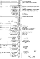
- FIG. 2 is a block diagram of an RF receiver module in accordance with an exemplary embodiment of the present invention.
- the RF receiver module is generally referred to by the reference number 200.
- Various components shown in FIG. 2 may be disposed on a base such as the base 102 ( FIG. 1 ).
- the RF receiver module 200 includes the connector 106 ( FIG. 1 ), which provides an interface to an audio system main PCB (not shown).
- certain components are common to all subsets of feature choices. Additional optional components (either hardware or software) may be added if needed to support a design having a subset of feature choices that includes optional features. If certain optional features are not chosen for a given RF receiver module design, the hardware and software components needed to provide and/or support those optional features are omitted from the design. In this manner, a specific, known group of components may be used to create a wide variety of RF receiver module designs based on different subsets of feature choices from a complete set of feature choices.
- RAM random access memory
- SDRAM synchronous dynamic random access memory
- the RAM 212 contains one or more software components that support operation of the RF receiver module 200.
- the software components contained in the RAM 212 may be uniquely configured to support only the particular subset of feature choices of the RF receiver module 200.
- different software components may be stored in the SD RAM 212 for different subsets of feature choices.
- a single, configurable software module capable of supporting any subset of feature choices may be stored in the RAM 212.
- the exemplary design illustrated in FIG. 2 may include either a single-arm RF receiver 202 or a diversity RF receiver 218, depending on whether the RF-type feature choice is selected to be single-arm configuration or diversity configuration.
- the single-arm RF receiver 202 is capable of supporting the reception of one channel of information.
- the diversity RF receiver 218 is capable of supporting reception of multiple channels of information.
- the single-arm RF receiver 202 is further identified by the part numbers SI2213/SI2215 in the exemplary embodiment illustrated in FIG. 2 .
- the diversity RF receiver 218 is further identified by the part number SI2214 in the exemplary embodiment illustrated in FIG. 2 .
- the remainder of this application assumes that the single-arm RF receiver 202 is installed in the RF receiver module 200 unless the diversity RF receiver 218 is specifically referenced.
- the baseband processor 210 receives output from the single-arm RF receiver 202.
- the base band processor 210 processes the received signal and delivers it to the connector 106, where it is passed on to the audio system main PCB (not shown).
- the single-arm RF receiver 202 is connected to a frequency synthesizer 204.
- the purpose of the frequency synthesizer 204 is to provide the correct local oscillator (LO) frequencies for the mixers contained in the RF receiver 202. These LO frequencies down convert the RF frequencies to a lower frequency so that the baseband chip ADCs will digitize the downconverted RF signal before demodulation and decoding.
- LO local oscillator
- Also connected to the RF receiver 202 is a reference crystal 206 and a RF connector 208.
- the reference crystal provides the clock for the entire receiver system.
- the RF connector is connected to an approved antenna module. This antenna module may contain a low noise amplifier (LNA) that will set the system noise figure.
- LNA low noise amplifier
- additional diversity antenna components are added to the RF receiver module 200.
- those additional diversity configuration components include a diversity voltage source 214 and a diversity RF oscillator 216.
- the additional diversity components are shown surrounded by plain dashed lines.
- the stack type feature choice for a particular RF receiver module design is smart (rather than stackless)
- a set of smart components is added to the RF receiver module 200.
- These smart components are illustrated as enclosed within boxes that comprise a dash followed by a period.
- the smart components comprise a smart processor 221, a first group of smart signal connections 222 and a second group of smart signal connections 224.
- the smart processor 221 is shown for purposes of illustration in FIG. 2 to be an Atmel AVR ATmega644 processor available from Atmel, although other suitable processors may be used.
- the first group of smart signal connections 222 and the second group of smart signal connections 224 are made between the smart processor 221 and the connector 106 in the exemplary embodiment illustrated in FIG. 2 .
- an additional set of Interoperable components and connections 226 is added to the RF receiver module 200.
- the Interoperable components and connections 226 are illustrated in FIG. 2 as enclosed within a box that comprises a long dash followed by two short dashes.
- the Interoperable components and connections 226 comprise an RF AUX regulator 228 in the embodiment illustrated in FIG. 2 .
- the RF AUX regulator 228 provides compatibility with the Interoperable Antenna Specification previously mentioned. Interoperable connections are made between the RF AUX regulator 228 and the connector 106.
- the RF receiver design set forth herein allows implementation of a wide range of subsets of feature choices from a complete set of feature choices with the same basic design. Because the design is modular, higher volumes can be processed using a fixed set of hardware and software components, therefore lowering manufacturing costs and increasing quality.
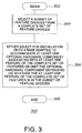
- FIG. 3 is a flow diagram showing a process in accordance with an exemplary embodiment of the present invention.
- the flow diagram is generally referred to by the reference number 300.
- the process begins.
- a subset of feature choices is selected from a complete set of feature choices.
- the complete set of feature choices are identified and valid subsets of feature choices are set forth in Table 1 above.
- Subsets of the complete set of feature choices correspond to individual code names set forth in Table 1.
- optional components are either selected or omitted from the RF receiver module design depending on whether features supported by those hardware or software components are among the subset of features chosen from the complete set of features for a given design.
- the process ends.
Landscapes
- Engineering & Computer Science (AREA)
- Computer Networks & Wireless Communication (AREA)
- Signal Processing (AREA)
- Circuits Of Receivers In General (AREA)
- Radio Transmission System (AREA)
- Transceivers (AREA)
Applications Claiming Priority (2)
| Application Number | Priority Date | Filing Date | Title |
|---|---|---|---|
| US11/653,022 US8515494B2 (en) | 2007-01-13 | 2007-01-13 | Highly configurable radio frequency (RF) module |
| EP08713100.9A EP2115875B1 (de) | 2007-01-13 | 2008-01-11 | Funkfrequenzmodul mit hoher konfigurierbarkeit |
Related Parent Applications (2)
| Application Number | Title | Priority Date | Filing Date |
|---|---|---|---|
| EP08713100.9A Division EP2115875B1 (de) | 2007-01-13 | 2008-01-11 | Funkfrequenzmodul mit hoher konfigurierbarkeit |
| EP08713100.9A Division-Into EP2115875B1 (de) | 2007-01-13 | 2008-01-11 | Funkfrequenzmodul mit hoher konfigurierbarkeit |
Publications (2)
| Publication Number | Publication Date |
|---|---|
| EP3024149A2 true EP3024149A2 (de) | 2016-05-25 |
| EP3024149A3 EP3024149A3 (de) | 2016-09-07 |
Family
ID=39609018
Family Applications (2)
| Application Number | Title | Priority Date | Filing Date |
|---|---|---|---|
| EP15003352.0A Withdrawn EP3024149A3 (de) | 2007-01-13 | 2008-01-11 | Funkfrequenzmodul mit hoher konfigurierbarkeit |
| EP08713100.9A Not-in-force EP2115875B1 (de) | 2007-01-13 | 2008-01-11 | Funkfrequenzmodul mit hoher konfigurierbarkeit |
Family Applications After (1)
| Application Number | Title | Priority Date | Filing Date |
|---|---|---|---|
| EP08713100.9A Not-in-force EP2115875B1 (de) | 2007-01-13 | 2008-01-11 | Funkfrequenzmodul mit hoher konfigurierbarkeit |
Country Status (5)
| Country | Link |
|---|---|
| US (3) | US8515494B2 (de) |
| EP (2) | EP3024149A3 (de) |
| JP (1) | JP5463145B2 (de) |
| CN (1) | CN101622792A (de) |
| WO (1) | WO2008086036A1 (de) |
Families Citing this family (4)
| Publication number | Priority date | Publication date | Assignee | Title |
|---|---|---|---|---|
| US8515494B2 (en) * | 2007-01-13 | 2013-08-20 | Panasonic Automotive Systems Company Of America, Division Of Panasonic Corporation Of North America | Highly configurable radio frequency (RF) module |
| CN102136630B (zh) * | 2010-11-23 | 2015-06-03 | 华为技术有限公司 | 天线装置、天线系统和天线电调方法 |
| US9893752B2 (en) * | 2014-10-31 | 2018-02-13 | Skyworks Solutions, Inc. | Diversity receiver front end system with variable-gain amplifiers |
| US10966538B2 (en) * | 2017-04-18 | 2021-04-06 | Hhg Ipco, Llc | Studio sofa with power headrests |
Family Cites Families (39)
| Publication number | Priority date | Publication date | Assignee | Title |
|---|---|---|---|---|
| US4485383A (en) * | 1980-12-01 | 1984-11-27 | Texas Instruments Incorporated | Global position system (GPS) multiplexed receiver |
| JP2690300B2 (ja) | 1986-10-15 | 1997-12-10 | 三菱電機株式会社 | ダイバシティ半導体集積回路 |
| US5347284A (en) * | 1991-02-28 | 1994-09-13 | Texas Instruments Incorporated | System and method for a digital navigation satellite receiver |
| US7119750B2 (en) * | 1993-04-27 | 2006-10-10 | Broadcom Corporation | Radio transceiver card communicating in a plurality of frequency bands |
| US6928302B1 (en) * | 1993-04-27 | 2005-08-09 | Broadcom Corporation | Radio card having independent antenna interface supporting antenna diversity |
| US5960344A (en) * | 1993-12-20 | 1999-09-28 | Norand Corporation | Local area network having multiple channel wireless access |
| US6295031B1 (en) * | 1993-12-23 | 2001-09-25 | Symbol Technologies, Inc. | Memory card assembly having an integral antenna |
| JPH0870262A (ja) * | 1994-08-29 | 1996-03-12 | Nec Corp | 移動体通信装置 |
| US5592480A (en) * | 1995-03-13 | 1997-01-07 | Carney; Ronald R. | Wideband wireless basestation making use of time division multiple-access bus having selectable number of time slots and frame synchronization to support different modulation standards |
| US6331974B1 (en) * | 1997-06-23 | 2001-12-18 | The Regents Of The University Of California | Chaotic digital code-division multiple access (CDMA) communication systems |
| US6151328A (en) * | 1998-12-31 | 2000-11-21 | Lg Information & Communications Ltd. | Apparatus and method for controlling power in code division multiple access system |
| JP2000278166A (ja) | 1999-03-26 | 2000-10-06 | Nec Corp | ソフトウエア携帯電話機 |
| US6522299B2 (en) * | 1999-04-08 | 2003-02-18 | Cypress Semiconductor Corp. | PC card retractable antenna |
| US6823169B2 (en) | 1999-05-25 | 2004-11-23 | Xm Satellite Radio, Inc. | Low cost interoperable satellite digital audio radio service (SDARS) receiver architecture |
| US6587448B1 (en) * | 1999-10-18 | 2003-07-01 | Lucent Technologies Inc. | Reconfigurable wireless system base station |
| US6538210B2 (en) * | 1999-12-20 | 2003-03-25 | Matsushita Electric Industrial Co., Ltd. | Circuit component built-in module, radio device having the same, and method for producing the same |
| EP1260028A2 (de) * | 2000-01-24 | 2002-11-27 | Radioscape Limited | Digitales funkbasisstation |
| JP3538369B2 (ja) | 2000-07-11 | 2004-06-14 | 長野日本無線株式会社 | ディジタル信号処理装置 |
| GB2407178B (en) | 2003-10-17 | 2006-07-12 | Toshiba Res Europ Ltd | Reconfigurable signal processing module |
| US6998709B2 (en) * | 2003-11-05 | 2006-02-14 | Broadcom Corp. | RFIC die-package configuration |
| JP2005167363A (ja) | 2003-11-28 | 2005-06-23 | Nec Corp | 携帯端末装置 |
| US20050143077A1 (en) | 2003-12-24 | 2005-06-30 | Hugo Charbonneau | System and method for designing a communications network |
| TWI227601B (en) * | 2003-12-26 | 2005-02-01 | Mediatek Inc | Transceiver module |
| JP4418250B2 (ja) * | 2004-02-05 | 2010-02-17 | 株式会社ルネサステクノロジ | 高周波回路モジュール |
| US7447171B2 (en) | 2004-06-14 | 2008-11-04 | Xm Satellite Radio, Inc. | Antenna diversity system |
| TW200603652A (en) | 2004-07-06 | 2006-01-16 | Syncomm Technology Corp | Wireless multi-channel sound re-producing system |
| US20060063494A1 (en) * | 2004-10-04 | 2006-03-23 | Xiangdon Zhang | Remote front-end for a multi-antenna station |
| US20060160486A1 (en) | 2005-01-14 | 2006-07-20 | Xm Satellite Radio, Inc. | Method and system for converting streaming digital data to FM modulated data |
| US7957351B2 (en) * | 2005-04-04 | 2011-06-07 | Qualcomm Incorporated | Method and apparatus for management of multi-carrier communications in a wireless communication system |
| US7526256B2 (en) * | 2005-05-25 | 2009-04-28 | Broadcom Corporation | Transformer-based multi-band RF front-end architecture |
| US7684779B2 (en) * | 2005-05-31 | 2010-03-23 | Broadcom Corporation | Wireless terminal baseband processor high speed turbo decoding module |
| US7295171B2 (en) * | 2005-10-17 | 2007-11-13 | Sierra Wireless, Inc. | Method and apparatus for switching between internal and external antennas in a device such as PC-Card modem |
| US20070190948A1 (en) * | 2006-02-14 | 2007-08-16 | Accton Technology Corporation | Radio frequency module |
| US7917132B2 (en) * | 2006-12-18 | 2011-03-29 | Broadcom Corporation | Direct memory download in a voice data and RF integrated circuit and method for use therewith |
| US7945216B2 (en) * | 2006-12-20 | 2011-05-17 | Broadcom Corporation | Single chip wireless transceiver operable to perform voice, data and radio frequency (RF) processing |
| US8515494B2 (en) * | 2007-01-13 | 2013-08-20 | Panasonic Automotive Systems Company Of America, Division Of Panasonic Corporation Of North America | Highly configurable radio frequency (RF) module |
| US7617342B2 (en) * | 2007-06-28 | 2009-11-10 | Broadcom Corporation | Universal serial bus dongle device with wireless telephony transceiver and system for use therewith |
| US20090253384A1 (en) * | 2008-04-04 | 2009-10-08 | Stmicroelectronics, Ltd. | Dual Mode Radio Frequency Front End Circuit |
| US8483333B2 (en) * | 2010-05-06 | 2013-07-09 | Mediatek Inc. | Methods for adjusting system clock in terms of operational status of non-baseband module, methods for peripheral device control adjustment, and electronic devices using the same |
-
2007
- 2007-01-13 US US11/653,022 patent/US8515494B2/en active Active
-
2008
- 2008-01-11 EP EP15003352.0A patent/EP3024149A3/de not_active Withdrawn
- 2008-01-11 EP EP08713100.9A patent/EP2115875B1/de not_active Not-in-force
- 2008-01-11 CN CN200880005957A patent/CN101622792A/zh active Pending
- 2008-01-11 JP JP2009545604A patent/JP5463145B2/ja not_active Expired - Fee Related
- 2008-01-11 WO PCT/US2008/000380 patent/WO2008086036A1/en not_active Ceased
-
2013
- 2013-07-16 US US13/942,762 patent/US9225366B2/en not_active Expired - Fee Related
-
2015
- 2015-11-17 US US14/943,076 patent/US9973222B2/en active Active
Non-Patent Citations (1)
| Title |
|---|
| None |
Also Published As
| Publication number | Publication date |
|---|---|
| EP2115875A1 (de) | 2009-11-11 |
| EP3024149A3 (de) | 2016-09-07 |
| US20160080014A1 (en) | 2016-03-17 |
| JP5463145B2 (ja) | 2014-04-09 |
| WO2008086036A1 (en) | 2008-07-17 |
| EP2115875B1 (de) | 2016-01-06 |
| US8515494B2 (en) | 2013-08-20 |
| JP2010516189A (ja) | 2010-05-13 |
| US9225366B2 (en) | 2015-12-29 |
| US20140020236A1 (en) | 2014-01-23 |
| US20080171528A1 (en) | 2008-07-17 |
| US9973222B2 (en) | 2018-05-15 |
| CN101622792A (zh) | 2010-01-06 |
| EP2115875A4 (de) | 2013-08-21 |
Similar Documents
| Publication | Publication Date | Title |
|---|---|---|
| EP2501155B1 (de) | Drahtloses System mit hoher Dichte | |
| CA2333660C (en) | Apparatus and method for processing signals selected from multiple data streams | |
| EP1863193B1 (de) | Digitaler Satellitenempfänger und Verfahren zur Schaltung zwischen mehreren Empfängerantennen unter Verwendung einer Diversitätschaltung | |
| US9973222B2 (en) | Highly configurable radio frequency (RF) module | |
| US20080254761A1 (en) | Radio frequency (RF) module | |
| CN202205892U (zh) | 整合式车用天线 | |
| KR20050033304A (ko) | Dmb 수신기 | |
| US8452328B2 (en) | Method and system of sharing a controller for a combined cellular phone and satellite radio | |
| US20110111712A1 (en) | Broadcasting receiver | |
| US7129895B2 (en) | Multiband concentric mast and microstrip patch antenna arrangement | |
| EP1686704A2 (de) | Auf einem Fahrzeug montierte Empfangsvorrichtung | |
| WO2008130341A1 (en) | Radio frequency (rf) module | |
| US20240213660A1 (en) | Antenna unit, antenna module and motor vehicle | |
| US8750785B2 (en) | Modular receiving unit | |
| KR100661121B1 (ko) | 무선 수신기 | |
| EP2288039A2 (de) | Dualband-Rundfunkempfänger | |
| KR960002952A (ko) | 위성방송 수신기의 수신주파수 변환방법 | |
| KR20050106512A (ko) | 멀티-채널 위성 신호 수신 장치 | |
| KR20080042447A (ko) | 저잡음 증폭기 내장형 안테나 모듈. | |
| US20080182529A1 (en) | Rds/rbds compatible fm transmitter | |
| KR20070067360A (ko) | 동조기 내장형 안테나 모듈 | |
| CA2757997A1 (en) | High density wireless system | |
| JP2008177960A (ja) | Fm送信機、ならびにそれを用いた電子機器 | |
| TWM333733U (en) | Digital conversion device for multiple-satellite receiver | |
| JPH1013269A (ja) | Fmチューナモジュール |
Legal Events
| Date | Code | Title | Description |
|---|---|---|---|
| AC | Divisional application: reference to earlier application |
Ref document number: 2115875 Country of ref document: EP Kind code of ref document: P |
|
| AK | Designated contracting states |
Kind code of ref document: A2 Designated state(s): AT BE BG CH CY CZ DE DK EE ES FI FR GB GR HR HU IE IS IT LI LT LU LV MC MT NL NO PL PT RO SE SI SK TR |
|
| PUAI | Public reference made under article 153(3) epc to a published international application that has entered the european phase |
Free format text: ORIGINAL CODE: 0009012 |
|
| RAP1 | Party data changed (applicant data changed or rights of an application transferred) |
Owner name: PANASONIC AUTOMOTIVE SYSTEMS COMPANY OF AMERICA, D |
|
| PUAL | Search report despatched |
Free format text: ORIGINAL CODE: 0009013 |
|
| AK | Designated contracting states |
Kind code of ref document: A3 Designated state(s): AT BE BG CH CY CZ DE DK EE ES FI FR GB GR HR HU IE IS IT LI LT LU LV MC MT NL NO PL PT RO SE SI SK TR |
|
| RIC1 | Information provided on ipc code assigned before grant |
Ipc: H04B 1/00 20060101AFI20160802BHEP Ipc: H04B 1/08 20060101ALI20160802BHEP |
|
| STAA | Information on the status of an ep patent application or granted ep patent |
Free format text: STATUS: THE APPLICATION HAS BEEN PUBLISHED |
|
| STAA | Information on the status of an ep patent application or granted ep patent |
Free format text: STATUS: THE APPLICATION IS DEEMED TO BE WITHDRAWN |
|
| 18D | Application deemed to be withdrawn |
Effective date: 20170308 |