EP3023960A2 - Motorisierte antriebsvorrichtung für eine heimanlage zum schliessen - Google Patents
Motorisierte antriebsvorrichtung für eine heimanlage zum schliessen Download PDFInfo
- Publication number
- EP3023960A2 EP3023960A2 EP15195071.4A EP15195071A EP3023960A2 EP 3023960 A2 EP3023960 A2 EP 3023960A2 EP 15195071 A EP15195071 A EP 15195071A EP 3023960 A2 EP3023960 A2 EP 3023960A2
- Authority
- EP
- European Patent Office
- Prior art keywords
- control unit
- signal
- electronic control
- wireless transmitter
- peripheral device
- Prior art date
- Legal status (The legal status is an assumption and is not a legal conclusion. Google has not performed a legal analysis and makes no representation as to the accuracy of the status listed.)
- Granted
Links
Images

Classifications
-
- G—PHYSICS
- G08—SIGNALLING
- G08C—TRANSMISSION SYSTEMS FOR MEASURED VALUES, CONTROL OR SIMILAR SIGNALS
- G08C17/00—Arrangements for transmitting signals characterised by the use of a wireless electrical link
- G08C17/02—Arrangements for transmitting signals characterised by the use of a wireless electrical link using a radio link
-
- G—PHYSICS
- G08—SIGNALLING
- G08C—TRANSMISSION SYSTEMS FOR MEASURED VALUES, CONTROL OR SIMILAR SIGNALS
- G08C2201/00—Transmission systems of control signals via wireless link
- G08C2201/10—Power supply of remote control devices
-
- G—PHYSICS
- G08—SIGNALLING
- G08C—TRANSMISSION SYSTEMS FOR MEASURED VALUES, CONTROL OR SIMILAR SIGNALS
- G08C2201/00—Transmission systems of control signals via wireless link
- G08C2201/40—Remote control systems using repeaters, converters, gateways
Definitions
- the present invention relates to a motorized drive device for manipulating a barrier closing an opening made in a building, an enclosure or a fence, and in particular a barrier such as a gate, a door, a gate, a shutter or a gate. any other equivalent equipment.
- It also relates to a home automation closure system comprising such a motorized drive device, a barrier and an associated peripheral device.
- Home automation closing systems comprising a motorized drive device, a barrier and a peripheral device.
- peripheral device in particular, a signaling device, such as for example a flashing light and / or an alarm, or an obstacle detection device.
- the motorized driving device comprises an electromechanical actuator and an electronic control unit.
- the electronic control unit of the motorized drive device comprises a power supply socket for supplying electrical power to a peripheral device.
- the peripheral device is non-autonomous in electrical energy.
- the peripheral device is electrically connected to the power supply socket of the electronic control unit of the motorized drive device.
- these domotic closure systems require cabling between the electronic control unit of the motorized drive device and the peripheral device controlled by a wired communication, which can be visible or masked, following the execution of work at the level of the home automation installation, and in particular of excavation, cable routing and recovery.
- WO 2010/095161 A1 discloses a home automation closure system comprising a motorized driving device, a barrier and a peripheral device.
- the motorized driving device comprises an electromechanical actuator, an electronic control unit, a wireless transmitter operatively connected to the electronic control unit, the wireless transmitter cooperating with a signaling device by a wireless communication.
- the wireless transmitter being integrated with the electronic control unit of the motorized driving device controls the signaling device by means of a wireless communication.
- the signaling device comprises an electronic control unit and a wireless receiver operatively connected to the electronic control unit.
- the wireless receiver operably connected to the electronic control unit of the signaling device is adapted to communicate with the wireless transmitter operably connected to the electronic control unit of the motorized driving device.
- this home automation closing system has the disadvantage of being adapted only to new home automation closure systems where the electronic control unit of the motorized drive device integrates a wireless transmitter, so that a device can be controlled. device by wireless communication.
- peripheral devices controlled by wireless communication can only be associated with motorized drive devices having an electronic control unit incorporating a wireless transmitter.
- the object of the present invention is to solve the aforementioned drawbacks and to propose a motorized drive device making compatible wired home automation systems compatible, in particular installations already in place, with new peripheral devices requiring wireless communication for their equipment. ordered.
- the present invention aims, in a first aspect, a motorized drive device of a home automation system comprising an electromechanical actuator, an electronic control unit, a wireless transmitter operatively connected to the electronic unit of control, the wireless transmitter being configured to cooperate with a peripheral device by wireless communication.
- the electronic control unit comprises a power supply plug.
- the wireless transmitter is electrically connected to the power supply socket of the electronic control unit so as to control the peripheral device by wireless communication.
- the wireless transmitter is an order issuing module external to the electronic control unit of the motorized driving device.
- command transmission module and the electronic control unit of the motorized drive device comprise separate printed circuit boards, and can be housed in separate housings.
- the wireless transmitter further includes means for converting a first signal, the first signal being a power supply signal from the power supply receptacle of the electronic control unit of the training device. motorized, in a second signal, the second signal being a control signal of the peripheral device.
- the electrical connection of the wireless transmitter to a power supply socket of the electronic control unit of the motorized drive device makes it possible to make compatible a wired home automation system, in particular an installation already in place, with a peripheral device requiring wireless communication for its command.
- a peripheral device requiring wireless communication can be controlled either from a motorized driving device comprising a wireless transmitter electrically connected to a power supply socket of its electronic control unit for electrically powering another device non-autonomous device electrical energy, or from another motorized driving device comprising an electronic control unit incorporating a wireless transmitter.
- the power supply plug of the electronic control unit of the motorized driving device allows either to control the peripheral device by wireless communication, following the electrical connection of the wireless transmitter thereon, or to supply electrical energy to another non-autonomous peripheral device for electrical energy by a wired electrical connection, following the electrical connection of electrical cables thereon and connecting the other peripheral device.
- the electrical connection of the wireless transmitter to a power supply socket of the electronic control unit of the motorized driving device makes it possible to avoid wiring, which may be visible or masked, between the electronic control unit of the motorized driving device and the peripheral device controlled by a wireless communication.
- the electrical connection of the wireless transmitter to a power supply of the electronic control unit of the motorized driving device makes it possible to avoid the execution of work at the level of the home automation system of closing, and in particular of excavation work, cable routing and recovery.
- the electrical connection of the wireless transmitter to a power supply socket of the electronic control unit of the motorized drive device also simplifies and reduces the installation time of the peripheral device operatively connected to the unit. electronic control device of the motorized drive device by wireless communication.
- the wireless transmitter can be electrically connected to the power supply socket of the electronic control unit via a wired link.
- the wireless transmitter may comprise at least one connection element detachably connected to the power supply socket of the electronic control unit of the motorized drive device, in practice a connection socket compatible with the power supply socket of the electronic control unit of the motorized drive device.
- the wireless transmitter of the motorized driving device is configured to transmit the second signal to a wireless receiver of the peripheral device, following the detection of a predetermined condition of operation of the electronic control unit of the motorized driving device.
- the first signal emitted by a control element of the electronic control unit of the motorized drive device is a pulse signal.
- the first signal emitted by a control element of the electronic control unit of the motorized drive device is a continuous signal.
- the wireless transmitter is configured to transmit the second signal called deactivation to the peripheral device, following the detection of a predetermined operating condition of the electronic control unit of the device. motorized drive or following the lapse of a predetermined period of time from the moment of transmission of the first signal.
- the wireless transmitter comprises a reserve of energy, so that the wireless transmitter is supplied with electrical energy by the energy reserve to emit the second signal to the peripheral device, following the interrupting the first signal emitted by a control element of the electronic control unit of the motorized drive device.
- This home automation closure system has similar characteristics and advantages to those described above in connection with the motorized drive device according to the invention.
- the peripheral device is configured so that the first signal triggers the operation of the peripheral device, following the transmission of the second signal by the wireless transmitter to the peripheral device.
- the peripheral device is configured so that the second signal transmitted by the wireless transmitter to the peripheral device, following the detection of a predetermined operating condition of the electronic unit of the device. control of the motorized drive device or following the flow of a predetermined period of time from the instant of the emission of the first signal, control the extinction of light and / or sound signals emitted by the peripheral device .
- the peripheral device comprises an independent electric power supply module.
- the present invention aims, according to a third aspect, a method of commissioning a home automation closure system according to the invention, comprising a step of electrically connecting the wireless transmitter to the electrical power supply socket. electronic control unit of the motorized driving device.
- This method of commissioning a home automation closure system has characteristics and advantages similar to those described above in connection with the motorized drive device according to the invention.
- the step of electrically connecting the wireless transmitter to the power supply socket of the electronic control unit of the motorized driving device is preceded by a step of electrically disconnecting a another non-autonomous peripheral device for electrical energy electrically connected to the same power supply socket of the electronic control unit of the motorized drive device.
- the home automation closure system 1 comprises at least one motorized drive device 2, at least one barrier 3 and at least one peripheral device 4.
- the barrier 3 is installed at an opening 5 made in a building, an enclosure or a fence.
- the barrier 3 makes it possible to seal the opening 5.
- the barrier 3 of the home automation closure system 1 is a movable barrier either by horizontal or vertical sliding, or by pivoting or by winding.
- the barrier 3 is a movable closing element such as a gate, a door, a grid, a shutter or any other equivalent equipment.
- the barrier 3 is driven in displacement by the motorized drive device 2.
- the barrier 3 of the domotic closure system 1 comprises a single leaf oscillating about an axis of rotation X theoretically substantially vertical and being perpendicular to the plane of the figure 1 .
- the flap of the barrier 3 is connected to the motorized drive device 2.
- the barrier 3 of the domotic closure system 1 comprises two leaves respectively oscillating about an axis of rotation X theoretically substantially vertical. Each leaf of the barrier 3 is connected to a motorized drive device 2.
- the motorized driving device 2 moves the barrier 3 between at least a first position and a second position, corresponding to an open position and a closed position.
- the motorized drive device 2 comprises an electromechanical actuator 6.
- the electromechanical actuator 6 comprises a first portion connected to the barrier 3 and a second portion connected to the building, the enclosure or the fence.
- the rear end of the electromechanical actuator 6 is articulated on a fixed support 7 of the building, enclosure or fence, so as to oscillate about a transverse axis substantially parallel to the axis of rotation X of barrier 3 and close to it.
- the barrier 3 of the home automation installation 1 is driven by the electromechanical actuator 6 and movable between the open position and the closed position.
- the motorized drive device 2 comprises an electronic control unit 8.
- the electromechanical actuator 6 is controlled by the electronic control unit 8 of the motorized drive device 2.
- the motorized drive device 2 also comprises at least one control interface 9, 10, 11 operatively connected to the electronic control unit 8 of the motorized drive device 2.
- the control interface 9, 10, 11 is connected, by a wired or non-wired connection, to the electronic control unit 8 of the motorized drive device 2.
- the control interface 9, 10, 11 comprises a control keyboard provided with selection elements and, possibly, display elements.
- the selection elements may be pushbuttons or sensitive keys
- the display elements may be light-emitting diodes
- an LCD display (acronym for the term “Liquid Crystal Display”) or TFT (acronym for the Anglo-Saxon term “Thin Film Transistor”).
- the selection and display elements can also be realized by means of a touch screen.
- the control interface 9, 10, 11 allows a user to control the motorized drive device 2 and, in particular, the electromechanical actuator 6 associated with the barrier 3, by pressing on one of the selection elements .
- the control interface 9, 10, 11 may be, for example, a local control unit 9.
- the local control unit 9 can be connected, in wired or wireless connection, with a central control unit 10.
- the central control unit 10 controls the local control unit 9, and if necessary other local control units similar and distributed in the building or the enclosure.
- the central control unit 10 may be in communication with a remote weather station outside the building or enclosure, including, in particular, one or more sensors that can be configured to determine, for example, a temperature, a brightness or a wind speed.
- a remote control 11, which may be a type of local control unit, and provided with a control keyboard further allows a user to intervene on the electromechanical actuator 6 and / or the central control unit 10. .
- the motorized drive device 2 is preferably configured to execute the opening or closing commands of the barrier 3 of the home automation closure system 1, which can be transmitted, in particular, by the remote control unit 11.
- the electronic control unit 8 of the motorized drive device 2 also comprises an order receiving module, in particular radio orders, emitted by a command transmitter, such as the remote control 11, intended to control the command. electromechanical actuator 6 of the motorized drive device 2.
- the order receiving module can also allow the reception of orders transmitted by wire means.
- the electronic control unit 8 of the motorized drive device 2 is disposed inside an electrical cabinet 13. Furthermore, the local control unit 9 is connected to the electrical cabinet 13 by a wired connection .
- the control means of the electromechanical actuator 6 of the motorized drive device 2 comprise hardware and / or software means.
- the hardware means may comprise at least one microcontroller.
- the electromechanical actuator 6 of the motorized drive device 2 comprises an electric motor (not shown).
- the electronic control unit 8 of the motorized drive device 2 is able to put into operation the electric motor of the electromechanical actuator 6, and in particular to allow the electric power supply of the electric motor.
- the electronic control unit 8 of the motorized drive device 2 controls, in particular, the electric motor, so as to open or close the barrier 3, as described above.
- the motorized driving device 2 also comprises a wireless transmitter 12.
- the wireless transmitter 12 is functionally connected to the electronic control unit 8 of the motorized drive device 2.
- the wireless transmitter 12 is configured to cooperate with the peripheral device 4 by a wireless communication.
- the wireless communication between the wireless transmitter 12 and the peripheral device 4 may be either monodirectional or bidirectional.
- the peripheral device 4 is a signaling device, and, more particularly, a flashing light.
- a signaling device comprises at least one lamp 14.
- said at least one lamp of the signaling device may be of the incandescent, halogen, or light-emitting diode type.
- the signaling device may comprise, in combination or independently, an alarm 18, in particular sound.
- Such a signaling device comprises a loudspeaker.
- the peripheral device 4 is autonomous in power supply.
- the peripheral device 4 is controlled by a wireless control and autonomous energy, or called without son.
- the peripheral device 4 comprises an independent electric power supply module, such as, for example, a battery.
- the battery is rechargeable.
- the battery can be recharged by means of a photovoltaic panel or any other energy recovery system that can be, in particular, thermal or aeraulic type.
- the electronic control unit 8 of the motorized drive device 2 comprises a power supply plug 15.
- the power supply plug 15 of the electronic control unit 8 of the motorized drive device 2 makes it possible, in particular, to supply electrical energy to another peripheral device (not shown) which is non-autonomous in electrical energy.
- the other non-autonomous peripheral device in electrical energy may also be a signaling device, and more particularly, a flashing light.
- a signaling device comprises at least one lamp.
- said at least one lamp of the signaling device may be of the incandescent, halogen, or light-emitting diode type.
- the signaling device may also include an alarm, particularly sound.
- Such a signaling device comprises a loudspeaker.
- the peripheral device 4 co-operating with the wireless transmitter 12 of the motorized drive device 2 is different from the peripheral device supplied with electrical energy by the electrical power supply plug 15 of the electronic control unit 8 of the motorized drive device. 2.
- the wireless transmitter 12 is electrically connected to this same power supply socket 15 of the electronic control unit 8 of the motorized drive device 2, so as to control the peripheral device 4 by means of a communication without thread.
- the wireless transmitter 12 of the motorized driving device 2 is electrically connected to the power supply socket 15 of the electronic control unit 8 of the motorized drive device 2 in place of the other device non-autonomous device in electrical energy, that is to say in replacement of the other peripheral device.
- the electrical connection of the wireless transmitter 12 to the power supply socket 15 of the electronic control unit 8 of the motorized drive device 2 makes it possible to maintain compatible a home automation installation already installed with the peripheral device. 4 requiring wireless communication for his order.
- the peripheral device 4 requiring wireless communication can be controlled either from another motorized driving device comprising an electronic control unit incorporating a wireless transmitter, as described in the document WO 2010/095161 A1 either from the motorized drive device 2 comprising the wireless transmitter 12 electrically connected to the power supply socket 15 of its electronic control unit 8 intended to supply electrically another non-autonomous peripheral device with electrical energy.
- the electrical power supply 15 of the electronic control unit 8 of the motorized driving device 2 makes it possible either to control the peripheral device 4, said wirelessly, by a wireless communication, following the electrical connection of the wireless transmitter 12 on it, or to supply electrical energy to another peripheral device non-autonomous electrical power, said wired, by a wired electrical connection, following the electrical connection of electrical cables thereon and connecting the other peripheral device.
- the electrical connection of the wireless transmitter 12 to the power supply socket 15 of the electronic control unit 8 of the motorized drive device 2 makes it possible to avoid wiring that may be visible or else masked, between the electronic control unit 8 of the motorized drive device 2 and the peripheral device 4 controlled by a wireless communication.
- the electrical connection of the wireless transmitter 12 to the power supply socket 15 of the electronic control unit 8 of the motorized drive device 2 makes it possible to avoid performing work at the level of the home automation installation 1, and in particular of excavation work, cable routing and recovery.
- the electrical connection of the wireless transmitter 12 to the power supply socket 15 of the electronic control unit 8 of the motor drive device 2 also makes it possible to simplify and reduce the installation time of the connected peripheral device 4. functionally to the electronic control unit 8 of the motor drive 2 by wireless communication.
- the wireless transmitter 12 is electrically connected to the power supply socket 15 of the electronic control unit 8 via a wire link.
- the wireless transmitter 12 of the motorized training device 2 is an order transmission module external to the electronic control unit 8 of the motorized training device 2.
- the wireless transmitter 12 and the electronic control unit 8 of the motor drive device 2 comprise separate printed circuit boards and are housed in separate housings.
- the wireless transmitter 12 comprises at least one branch element detachably connected to the power supply socket 15 of the electronic control unit 8 of the motorized drive device 2.
- the wireless transmitter 12 of the motorized driving device 2 is electrically connected to the power supply plug 15 of the electronic control unit 8 of the motor drive device 2 by means of two power supply cables. and in particular of short length, which may be for example of the order of 1 to 100 millimeters.
- the wireless transmitter 12 of the motorized drive device 2 is electrically connected to the electrical power supply plug 15 of the electronic control unit 8 of the motorized drive device 2 by means of two electrical plugs.
- the wireless transmitter 12 can be said pluggable or pin.
- Said at least one branch element of the wireless transmitter 12 may be, for example, a power supply cable or an electrical plug.
- the wireless transmitter 12 comprises two electrical connection elements.
- the wireless transmitter 12 of the motorized drive device 2 comprises a housing.
- the housing of the wireless transmitter 12 is disposed inside the electrical cabinet 13 of the motorized drive device 2.
- the peripheral device 4 comprises an electronic control unit 16, a wireless receiver 17 operatively connected to the electronic control unit 16.
- the electronic control unit 16 of the peripheral device 4 is different from the electronic control unit 8 of the motorized drive device 2.
- the wireless receiver 17 of the peripheral device 4 is configured to communicate, by a non-wired link, with the wireless transmitter 12 electrically connected to the power supply socket 15 of the electronic control unit 8 of the training device. motorized 2.
- the wireless communication between the wireless transmitter 12 of the motorized drive device 2 and the wireless receiver 17 of the peripheral device 4 is a radio wave communication.
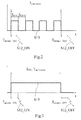
- the wireless transmitter 12 of the motorized drive device 2 comprises means for converting a first signal S15, the first signal S15 being a power supply signal coming from the power supply plug 15 of the electronic control unit 8 of the motorized driving device 2, in a second signal S12_ON, S12_OFF, the second signal S12_ON, S12_OFF being a control signal of the peripheral device 4.
- the electronic control unit 8 of the motorized drive device 2 comprises at least one control element, in particular a microcontroller, transmitting the first signal S15 to the wireless transmitter 12 electrically connected to the power supply plug 15 of the electronic control unit 8 of the motor drive device 2, so that the wireless transmitter 12 automatically transmits the second signal S12_ON, S12_OFF to the wireless receiver 17 of the peripheral device 4.
- a control element in particular a microcontroller
- the first signal S15 emitted by the control element of the electronic control unit 8 of the motor drive device 2 is a power supply signal of a peripheral device, in particular of the other non-autonomous peripheral device. in electrical energy.
- the first signal S15 emitted by the control element of the electronic control unit 8 of the motorized drive device 2 is an electrical signal.
- the first signal S15 emitted by the control element of the electronic control unit 8 of the motorized drive device 2 can correspond, in particular, to a current motion signal implemented by the electromechanical actuator 6 of the motorized drive device 2.
- the transmission of the first signal S15 by the control element of the electronic control unit 8 of the motorized drive device 2 may correspond to the execution of an order of operation of the electromechanical actuator 6 by the electronic control unit 8 of the motorized drive device 2.
- This operating order of the electromechanical actuator 6 can be issued by the local control unit 9 or the central control unit 10.
- the interruption of the first signal S15 by the control element of the electronic control unit 8 of the motorized drive device 2 may correspond to the execution of a stop command of the electromechanical actuator 6 by the electronic control unit 8 of the motorized drive device 2.
- This stop command of the electromechanical actuator 6 can be issued by the local control unit 9, the central control unit 10 or by a connected detection sensor functionally to the electronic control unit 8 of the motorized drive device 2, which can be, in particular, a limit switch, obstacle or wind.
- the wireless transmitter 12 When the wireless transmitter 12 is electrically connected to the power supply socket 15 of the electronic control unit 8 of the motorized drive device 2, the wireless transmitter 12 is supplied with electrical energy by this socket. power supply 15, following the activation of the first signal S15, or in other words during the transition to an ON state of the first signal S15.
- the second signal S12_ON, S12_OFF emitted by the wireless transmitter 12 of the motorized drive device 2 is a control signal by wireless communication of the peripheral device 4.
- the second signal S12_ON, S12_OFF emitted by the wireless transmitter 12 can correspond to several control commands provided by the electronic control unit 8 of the motor drive device 2 through the first signal S15. These control commands may correspond, for example, to the activation or deactivation command of the peripheral device 4.
- the second signal S12_ON, S12_OFF emitted by the wireless transmitter 12 is a radio signal.
- the means for converting the wireless transmitter 12 of the motorized drive device 2 making it possible to convert an electrical signal into a radio frequency signal may be, in particular, a microcontroller and / or electronic components, which are well known to those skilled in the art. .
- the wireless transmitter 12 of the motor drive device 2 is configured to transmit the second signal S12_ON, S12_OFF to the wireless receiver 17 of the peripheral device 4, following the detection of a predetermined operating condition of the electronic unit. 8 of the motor drive 2.
- the predetermined condition of operation of the electronic control unit 8 of the motorized driving device 2 may correspond to the operation control of the electromechanical actuator 6, so as to move the barrier 3, or to the control of Stopping the electromechanical actuator 6.
- the predetermined condition of operation of the electronic control unit 8 of the motorized drive device 2 may also correspond to a presence detection by obstacle detection sensors operatively connected to the electronic control unit 8 of the device. motorized drive 2 or switching detection of the electrical power supply of the electronic control unit 8 of the motor drive device 2 to a backup battery, in particular when the power supply is cut off by the mains network.
- the electronic control unit 16 of the peripheral device 4 performs a predetermined action, in response to the reception by the wireless receiver 17 of the peripheral device 4 of a control signal transmitted by the wireless transmitter 12 electrically connected to the socket. power supply 15 of the electronic control unit 8 of the motorized drive device 2.
- the predetermined action performed by the electronic control unit 16 of the peripheral device 4 is the activation or deactivation of the lamp 14 of the peripheral device 4 and / or the activation or deactivation of the alarm 18 of the peripheral device 4. .
- the predetermined action performed by the electronic control unit 16 of the peripheral device 4 can also be the activation or deactivation of other elements emitting a light signal and / or sound, such as for example an infrared transmitting cell.
- the wireless transmitter 12 emits the second signal called the second activation signal S12_ON.
- the transmitter without wire 12 emits the second signal called second deactivation signal S12_OFF.
- the first signal S15 emitted by the control element of the electronic control unit 8 of the motorized drive device 2 is a pulse signal, that is to say having successively a low state and a high state of cyclic way.
- this signal pulsing allows, in particular, to supply electrical energy to the other non-autonomous peripheral device in electrical energy in a clocked manner.
- the timing given by the pulse signal makes it possible to generate the flashing light signals of the lamp and / or the intermittent sound signals of the alarm of the other non-autonomous peripheral device with electrical energy.
- the other non-autonomous peripheral device of electrical energy electrically connected to the power supply plug 15 of the electronic control unit control 8 of the motorized drive device 2 is a peripheral device comprising a lamp and / or an alarm controlled by an electrical control signal, called power signal, having a timing corresponding to the predetermined frequency of flashing of the lamp or emission sound of the alarm.
- the first pulse signal S15 makes it possible, in particular, to triggering the operation of the peripheral device 4, said wireless, especially from the start of the pulse signal.
- the pulse signal emitted by the control element of the electronic control unit 8 of the motor drive device 2 triggers the transmission by the wireless transmitter 12 of the second activation signal S12_0N corresponding to the activation of the lamp 14 and / or the alarm 18 of the peripheral device 4.
- the second activation signal S12_ON emitted by the wireless transmitter 12 is implemented following a change of state, in particular the first state change, of the pulse signal emitted by the control element of the electronic control unit 8 of the motorized drive device 2, in particular during a transition from a low state to a high state of the pulse signal.
- the second activation signal S12_ON emitted by the wireless transmitter 12 can be triggered by the transition from a high state to a low state of the first pulse signal S15.
- the electronic control unit 16 of the peripheral device 4 triggers the generation of flashing light signals from the lamp 14 and / or sound signals intermittent alarm 18.
- the pulse signal makes it possible to control the timing of the flashing light signals of the lamp 14 and / or the intermittent sound signals of the alarm 18 of the peripheral device 4 by the periodic sending of the second signal S12_ON from the transmitter without wire 12.
- the electronic control unit 16 of the peripheral device 4 can thus generate the flashing light signals of the lamp 14 and / or the intermittent sound signals of the alarm 18 of the peripheral device 4 according to the predetermined timing of the pulse signal coming from the control element of the electronic control unit 8 of the motor drive device 2.
- the electronic control unit 16 of the peripheral device 4 can generate the flashing light signals of the lamp 14 and / or the intermittent sound signals of the alarm 18 of the peripheral device 4 according to a predetermined timing different from the predetermined timing of the signal at the pulses from the control element of the electronic control unit 8 of the motorized driving device 2, in particular as long as the wireless receiver 17 of the peripheral device 4 receives the second signal S12_ON transmitted periodically by the transmitter without wire 12.
- the wireless transmitter 12 emits the second deactivation signal S12_OFF corresponding to the deactivation of the lamp 14 and / or the alarm 18 of the peripheral device 4.
- the second deactivation signal S12_OFF emitted by the wireless transmitter 12 is implemented following a change of state of the pulse signal emitted by the control element of the electronic control unit 8 of the control device.
- motorized drive 2 in particular during a transition from a high state to a low state of the pulse signal.
- the second deactivation signal S12_OFF emitted by the wireless transmitter 12 can be triggered by the transition from a low state to a high state of the first pulse signal S15.
- the electronic control unit 16 of the peripheral device 4 interrupts the generation of flashing light signals from the lamp 14 and / or intermittent sound signals of the alarm 18.
- the first signal S15 emitted by the control element of the electronic control unit 8 of the motorized drive device 2 is a continuous signal, that is to say having a single change of state, for example a low state to a high state or a high state to a low state, to trigger the transmission of the second signal S12_ON, S12_OFF emitted by the wireless transmitter 12.
- this continuous signal only makes it possible to trigger the supply of electrical energy to the other non-autonomous peripheral device in electrical energy and to control the activation or deactivation of the other non-autonomous peripheral device in electrical energy, the timing of flashing light signals from the lamp and / or intermittent alarm sounds being generated by an electronic control unit of the other non-self-powered peripheral device.
- the wireless transmitter 12 is electrically connected to the same electrical power supply 15 of the electronic control unit 8 of the motor drive device 2
- the first signal S15 said continuous only allows to trigger the setting in operation of the peripheral device 4, said wireless, especially as soon as the change of state of the continuous signal.
- the wireless transmitter 12 when the wireless transmitter 12 is electrically connected to the power supply socket 15 of the electronic control unit 8 of the motorized driving device 2, the continuous signal emitted by the control element of the unit electronic control 8 of the motor drive device 2 triggers the transmission by the wireless transmitter 12 of the second activation signal S12_ON corresponding to the activation of the lamp 14 and / or the alarm 18 of the peripheral device 4 , following the change of state of this continuous signal.
- the second activation signal S12_ON emitted by the wireless transmitter 12 is implemented following the transition to the ON state of the continuous signal emitted by the control element of the electronic control unit 8 of the device motorized drive 2, in particular during a transition from a low state to a high state of the continuous signal.
- the second activation signal S12_ON emitted by the wireless transmitter 12 can be triggered by the transition from a high state to a low state of the first signal S15 said continuous.
- the electronic control unit 16 of the peripheral device 4 comprises means for timing the flashing light signals of the lamp 14 and / or the intermittent audible signals from the alarm 18 of the peripheral device 4.
- the electronic control unit 16 of the peripheral device 4 makes it possible to generate the timing of the flashing light signals of the lamp 14 and / or the intermittent sound signals of the alarm 18 of the peripheral device 4.
- the electronic control unit 16 of the peripheral device 4 is autonomous to generate the timing of the flashing light signals of the lamp 14 and / or the intermittent sound signals of the alarm 18 of the peripheral device 4.
- the timing means of the electronic control unit 16 of the peripheral device 4 are activated, following the transmission of the second activation signal S12_ON by the wireless transmitter 12 having been generated by the change of state of the first signal S15 emitted by the control element of the electronic control unit 8 of the motorized drive device 2.
- the electronic control unit 16 of the peripheral device 4 makes it possible to generate the timing of the flashing light signals of the lamp 14 and / or the intermittent sound signals of the alarm 18 of the peripheral device 4 without using a pulsed signal emitted by the control element of the electronic control unit 8 of the motorized drive device 2, but more simply to a continuous signal emitted by the control element of the electronic control unit. control 8 of the motorized drive device 2.
- the electronic control unit 16 of the peripheral device 4 triggers the generation of flashing light signals from the lamp 14 and / or sound signals intermittent alarms18.
- the electronic control unit 16 of the peripheral device 4 generates and outputs the flashing light signals of the lamp 14 and / or the intermittent sound signals of the alarm 18 of the peripheral device 4 at a predetermined timing.
- the electronic control unit 16 of the peripheral device 4 generates the flashing light signals of the lamp 14 and / or the intermittent sound signals of the alarm 18 of the peripheral device 4 and itself generates the predetermined timing of these signals controlling the lamp 14 and / or the alarm 18.
- the predetermined timing of the flashing light signals of the lamp 14 and / or intermittent sound signals of the alarm 18 of the peripheral device 4 can be realized during the manufacture of the peripheral device 4, or adjusted by the user by means of a selection element, such as for example a button, of the device device 4 or defined according to the frequency of the first signal S15 said pulse.
- the predetermined timing of the flashing light signals of the lamp 14 and / or the intermittent sound signals of the alarm 18 of the peripheral device 4 may also be dependent on the predetermined operating condition of the electronic control unit 8 of the training device. detected motor 2 having caused the emission of the second activation signal S12_ON by the wireless transmitter 12.
- the data associated with the predetermined timing of the flashing light signals of the lamp 14 and / or intermittent sound signals of the alarm 18 of the peripheral device 4 can be contained in the frame of the second activation signal S12_ON emitted by the wireless transmitter 12.
- the wireless transmitter 12 emits a second deactivation signal S12_OFF corresponding to the deactivation of the lamp 14 and / or the alarm 18 of the peripheral device 4.
- the second deactivation signal S12_OFF emitted by the wireless transmitter 12 is implemented following the transition to the OFF state of the continuous signal emitted by the control element of the electronic control unit 8 of the control device.
- motorized drive 2 in particular during a transition from a high state to a low state of the continuous signal.
- the second deactivation signal S12_OFF emitted by the wireless transmitter 12 can be triggered by the transition from a low state to a high state of the first signal S15 said continuous.
- the electronic control unit 16 of the peripheral device 4 interrupts the generation of flashing light signals from the lamp 14 and / or intermittent sound signals of the alarm 18.
- the second activation signal S12_ON emitted by the wireless transmitter 12 is implemented following the flow of a predetermined period of time T waiting_ON to from the moment of the transmission of the first signal S15 by the control element of the electronic control unit 8 of the motorized drive device 2.
- the second activation signal S12_ON emitted by the wireless transmitter 12 is implemented only if the first signal S15 is emitted during the predetermined period of time T waiting _ ON , so as to avoid inadvertent tripping of the peripheral device 4, and in particular the generation of flashing light signals from the lamp 14 and / or intermittent sound signals from the alarm 18 of the peripheral device 4, in particular because of possible disturbances of the wireless transmitter 12 and / or the control element of the electronic control unit 8 of the motorized drive device 2.
- the predetermined time period T wait_ON from the instant of the transmission of the first signal S15 by the control element of the electronic control unit 8 of the motor drive device 2 can for example, to be less than a power supply period T ON of the first pulse signal S15 supplied with electrical energy to the wireless transmitter 12 or to be greater than a period comprising a supply period T ON and a cut-off period T OFF of the first signal S15 says pulses supplying electrical energy to the wireless transmitter 12.
- the power supply period T ON of the first signal S15 said pulses supplying electrical energy to the wireless transmitter 12 corresponds to the same power supply period T ON of the first pulse signal S15 said supplying electrical energy to the other peripheral device non-autonomous in electrical energy.
- the cut-off period T OFF of the first signal S15 said pulses supplying electrical energy to the wireless transmitter 12 corresponds to the same cut-off period T OFF of the first signal S15 called pulses supplying electrical energy to the other non-peripheral device autonomous in electrical energy.
- the predetermined period of time T waiting_ON from the instant of the transmission of the first signal S15 by the control element of the electronic control unit 8 of the motorized drive device 2 corresponds to at a fraction of the supply period T ON of the first signal S15 said continuous supplying electrical energy to the wireless transmitter 12, also corresponding to a same fraction of the supply period T ON of the first signal S15 said continuous supplying electrical energy the other non-autonomous peripheral device into electrical energy.
- the second deactivation signal S12_OFF emitted by the wireless transmitter 12 is implemented following the flow of a predetermined period of time T waiting_off from the instant of the interruption of the first signal S15 by the control element of the electronic control unit 8 of the motorized drive device 2.
- the second deactivation signal S12_OFF emitted by the wireless transmitter 12 is implemented only if the first signal S15 is interrupted during the predetermined period of time T waiting_off , so as to avoid an inadvertent stop of the peripheral device 4, and in particular, the switching off of flashing light signals of the lamp 14 and / or intermittent sound signals of the alarm 18 of the peripheral device 4, in particular because of possible disturbances of the wireless transmitter 12 and / or the element control unit of the electronic control unit 8 of the motorized drive device 2.
- the predetermined period of time T waiting_off from the moment of the interruption of the first signal S15 by the control element of the electronic control unit 8 of the motor drive device 2 is greater than a cut-off period T OFF of the first signal S15 said pulses supplying electrical energy to the wireless transmitter 12, also greater than the same cut-off period T OFF of the first signal S15 says pulses supplying electrical energy to the other non-autonomous peripheral device in electrical energy.
- the predetermined period of time T waiting_off from the moment of the interruption of the first signal S15 by the control element of the electronic control unit 8 of the motor drive device 2 corresponds to at a predetermined time.
- the predetermined time periods T wait_ON and T wait_OFF may be identical or different durations.
- the predetermined time periods T wait_ON and T wait_off can be fixed durations.
- the predetermined time periods T wait_ON and T wait_off can be adjustable durations.
- the adjustment of the duration of the predetermined time periods T waiting_ON and T waiting_off can be implemented by means of a selection element of the wireless transmitter 12.
- the user can modify the value of the duration of the predetermined time periods T wait_ON and T wait_OFF by means of the selection element of the wireless transmitter 12.
- the selection element of the wireless transmitter 12 allowing the adjustment of the duration of the predetermined time periods T wait_ON and T wait_OFF can be a jumper.
- the adjustment of the duration of the predetermined time periods T wait_ON and T wait_OFF can be implemented automatically by the wireless transmitter 12, as a function of the frequency of the first signal S15, said pulse signal, issued by the control element of the electronic control unit 8 of the motorized drive device 2.
- the wireless transmitter 12 comprises a reserve of energy, so that the wireless transmitter 12 is supplied with electrical energy by the energy reserve to emit the second deactivation signal S12_OFF to the peripheral device 4, following the interruption of the first signal S15 emitted by the control element of the electronic control unit 8 of the motorized drive device 2.
- the wireless transmitter 12 is supplied with electrical energy by the energy reserve, following the interruption of the first signal S15 by the control element of the electronic control unit 8 of the motorized drive device 2 .
- the wireless transmitter 12 When the first signal S15 is interrupted by the control element of the electronic control unit 8 of the motorized drive device 2, or in other words corresponds to an OFF state, the wireless transmitter 12 is no longer supplied with power. electrical energy through the power supply plug 15 of the electronic control unit 8 of the motorized drive device 2.
- the wireless transmitter 12 is kept active by the energy reserve, so as to be able to transmit the second deactivation signal S12_OFF to the peripheral device 4, following the interruption of the first signal S15.
- the energy reserve makes it possible to keep the wireless transmitter 12 active during the predetermined period of time T wait_off , so that it can transmit the second deactivation signal S12_OFF to the peripheral device 4, following the lapse of the predetermined period of time T waiting_OFF starting from the instant of the interruption of the first signal S15 by the control element of the electronic unit 8 of the motor drive 2.
- the electronic control unit 8 of the motorized drive device 2 can switch to a power saving mode, following the interruption of the first signal S15, so as to minimize the electrical energy consumption of the motorized driving device 2.
- the energy reserve of the wireless transmitter 12 may be a capacitor or accumulator, which can be charged when the first signal S15 is transmitted by the control element of the electronic control unit 8 of the device.
- motorized drive 2 or a battery, such as for example a battery.
- the wireless transmitter 12 transmits the second deactivation signal S12_OFF to the peripheral device 4, said wireless, following the flow of a predetermined period of time T activation from the moment of the transmission of the first signal S15 by the control element of the electronic control unit 8 of the motorized drive device 2, so as to control the extinction of light and / or sound signals emitted by the peripheral device 4, and in particular the stopping of the lamp 14 and / or the alarm 18 of the peripheral device 4.
- the wireless transmitter 12 comprises a timer for determining the period of time elapsed from the instant of the transmission of the first signal S15, so as to be able to transmit the second deactivation signal S12_OFF, following the reaching the predetermined time period T activation .
- the timer may be an internal counting element of a microcontroller of the wireless transmitter 12, or else a counting element associated with a clock of the wireless transmitter 12.
- the wireless transmitter 12 transmits the second deactivation signal S12_OFF to the peripheral device 4, said wireless, following the reception by the command reception module of the electronic control unit 8 of the motorized drive device 2 of a stop command of the electromechanical actuator 6.
- the stop command of the electromechanical actuator 6 received by the command receiving module of the electronic control unit 8 of the motorized drive device 2 can come from the local control unit 9, from the central control unit 10, or a detection sensor operatively connected to the electronic control unit 8 of the motorized drive device 2.
- the electronic control unit 16 of the peripheral device 4 emits a stop signal, following the lapse of a predetermined period of time, so as to control the stopping of the peripheral device 4, and in particular , stopping the lamp 14 and / or the alarm 18 of the peripheral device 4.
- the wireless transmitter 12 transmits only the second activation signal S12_ON to the peripheral device 4.
- the stop signal emitted by the electronic control unit 16 of the peripheral device 4 replaces the second deactivation signal S12_OFF emitted by the wireless transmitter 12 to the peripheral device 4, so as to switch the electronic control unit 8 of the motor drive device 2 in a power saving mode, following the transmission of the first signal S15 by the control element of the electronic control unit 8 of the motor drive device 2.
- the peripheral device 4 is autonomous, following the reception of the second activation signal S12_ON by the wireless receiver 17, and the electronic control unit 8 of the motorized drive device 2 minimizes its energy consumption. electrical, following the transmission of the first signal S15 by the control element of the electronic control unit 8 of the motorized drive device 2.
- the wireless transmitter 12 does not transmit the second deactivation signal S12_OFF to the peripheral device 4, so that the wireless transmitter 12 does not need to monitor, and in particular to convert and process, the first signal S15 emitted by the control element of the electronic control unit 8 of the motorized drive device 2, following the transmission of the second activation signal S12_ON by the wireless transmitter 12.
- the electronic control unit 16 of the peripheral device 4 comprises a timer making it possible to determine the period of time elapsed from the instant of the transmission of the first signal S15, so as to be able to emit the stop signal, after reaching the predetermined period of time.
- the timer may be an internal counting element of a microcontroller of the electronic control unit 16 of the peripheral device 4, or else a counting element associated with a clock of the electronic control unit 16 of the peripheral device 4.
- the wireless transmitter 12 transmits again the second activation signal S12_ON to the peripheral device 4, said wireless, following the flow of a predetermined period of time, so as to prolong the duration of activation of the light and / or sound signals emitted by the peripheral device 4.
- the duration of the predetermined period of time may be of the order of twenty seconds.
- the return of the second activation signal S12_ON by the wireless transmitter 12 to the peripheral device 4 makes it possible to keep the light and / or sound signals emitted by the peripheral device 4 active as long as the second deactivation signal S12_OFF does not exist. is not transmitted by the wireless transmitter 12 to the peripheral device 4.
- the wireless transmitter 12 includes a timer for determining the time period elapsed from the instant of the transmission of the first signal S15, so that the second activation signal S12-ON can be transmitted again. after reaching the predetermined period of time.
- the timer may be an internal counting element of a microcontroller of the wireless transmitter 12, or else a counting element associated with a clock of the wireless transmitter 12.
- the return of the second activation signal S12_ON by the wireless transmitter 12 to the peripheral device 4 may make it possible to reset a timer of the electronic control unit 16 of the peripheral device 4, so as to keep the signals active. light and / or sound emitted by the peripheral device 4.
- the timer of the electronic control unit 16 of the peripheral device 4 makes it possible to interrupt the light and / or sound signals emitted by the peripheral device 4, following the passage of a period of maximum operating time of the peripheral device 4 , in particular in the absence of reception of the second deactivation signal S12_OFF by the wireless receiver 17 of the electronic control unit 16 of the peripheral device 4, so as to minimize the power consumption of the peripheral device 4, and in particular to save the battery thereof.
- the return of the second activation signal S12_ON by the wireless transmitter 12 to the peripheral device 4 is implemented provided that the first signal S15 is kept active by the control element of the electronic control unit. 8 of the motor drive 2.
- the return of the second activation signal S12_ON by the wireless transmitter 12 to the peripheral device 4 is implemented provided that the first signal S15 said pulse periodically switches between the ON state and the OFF state.
- the return of the second activation signal S12_ON by the wireless transmitter 12 to the peripheral device 4 is implemented provided that the first signal S15 said continuous is maintained in the ON state.
- the return of the second activation signal S12_ON by the wireless transmitter 12 to the peripheral device 4 can be implemented according to the predetermined operating condition of the electronic control unit 8 of the training device. detected motor 2 having caused the first transmission of the second activation signal S12_ON by the wireless transmitter 12.
- the commissioning method comprises a step of electrically connecting the wireless transmitter 12 to the power supply socket 15 of the electronic control unit 8 of the motorized drive device 2.
- the step of electrically connecting the wireless transmitter 12 to the power supply socket 15 of the electronic control unit 8 of the motor drive device 2 is preceded by a disconnection step electrical device of the other non-autonomous peripheral device into electrical energy electrically connected to the same power supply socket 15 of the electronic control unit 8 of the motorized drive device 2.
- the pairing action of the wireless transmitter 12 electrically connected to the power supply socket 15 of the electronic control unit 8 of the motor drive device 2 with the peripheral device 4 consists in exchanging data, at least one identifier, between the wireless transmitter 12 and the peripheral device 4, so as to allow wireless communication between them.
- the peripheral device 4 is initially configured in a learning mode.
- the configuration of the peripheral device 4 in a learning mode can be implemented during the commissioning of the peripheral device 4, in particular by the first powering on thereof, or when selecting this mode of operation. learning by a selection element of the peripheral device 4, such as for example a button.
- the wireless transmitter 12 is supplied with electrical energy via the first signal S15 through the power supply plug 15 of the electronic control unit 8 and transmits the second activation signal S12_ON to the peripheral device 4.
- the electronic control unit 16 of the peripheral device 4 stores the identifier of the wireless transmitter 12.
- the wireless transmitter 12 is paired with the peripheral device 4, so as to allow wireless communication between the wireless transmitter 12 and the peripheral device 4.
- the order of operation of the electromechanical actuator 6 received by the command receiving module of the electronic control unit 8 of the motorized drive device 2 may be an order issued by the local control unit 9. or the central control unit 10.
- an order of actuation of the actuator is executed by the electronic control unit 8 of the motorized drive device 2.
- the wireless transmitter 12 is supplied with electrical energy via the first signal S15 through the power supply plug. 15 of the electronic control unit 8 and sends the second activation signal S12_ON to the peripheral device 4.
- the electronic control unit 16 of the peripheral device 4 stores the identifier of the wireless transmitter 12.
- the wireless transmitter 12 is paired with the peripheral device 4, so as to allow wireless communication between the wireless transmitter 12 and the peripheral device 4.
- the configuration of the wireless transmitter 12 in a pairing mode can be implemented when selecting this mode by a selection element of the wireless transmitter 12, such as for example a button.
- the order of operation of the electromechanical actuator 6 executed by the electronic control unit 8 of the motor drive device 2 may be either an order issued by the local control unit 9 or the central control unit 10 and then received by the command receiving module of the electronic control unit 8 of the motor drive device 2, or correspond to a declaration of the peripheral device 4 in the electronic control unit 8 of the motorized drive device 2, in particular through the selection and display elements of the control interface 9, 10, 11 operatively connected to the electronic control unit 8 of the motorized drive device 2.
- the pairing action of the wireless transmitter 12 electrically connected to the power supply socket 15 of the electronic unit of FIG. control 8 of the motor drive 2 with the peripheral device 4 can be implemented by an activation of a selection element of the wireless transmitter 12, in particular by pressing a button, so as to issue a pairing signal to the peripheral device 4.
- the electronic control unit 16 of the peripheral device 4 stores the identifier of the wireless transmitter 12.
- the wireless transmitter 12 is paired with the peripheral device 4, so as to allow wireless communication between the wireless transmitter 12 and the peripheral device 4.
- such a selection element of the wireless transmitter 12 can be activated after the pairing of the wireless transmitter 12 with the peripheral device 4, so as to test the wireless communication between the wireless transmitter 12 and the peripheral device 4 or to deactivate the pairing previously implemented between the wireless transmitter 12 and the peripheral device 4.
- the electrical connection of the wireless transmitter to a power supply socket of the electronic control unit of the motorized drive device makes it possible to maintain compatible an existing home automation installation already installed with a peripheral device. requiring wireless communication for his order.
- a peripheral device requiring wireless communication can be controlled either from a motorized driving device comprising a wireless transmitter electrically connected to a power supply socket of its electronic control unit for electrically powering another device non-autonomous device electrical energy, or from another motorized driving device comprising an electronic control unit incorporating a wireless transmitter.
- the peripheral device may be an obstacle detection device, such as for example an infrared emitter cell, in particular autonomous in electrical energy.
- the infrared transmitter cell is intended to receive an order transmitted by the wireless transmitter 12, so as to emit an infrared light beam for the detection of an obstacle or a presence between the latter and an infrared receiver cell.
- the infrared receiver cell can be electrically connected to the electronic control unit 8 of the motorized drive device 2 by a wired connection or be autonomous in electrical energy.
- the electrical connection of the wireless transmitter 12 to the power supply socket 15 of the electronic control unit 8 of the motorized drive device 2 can also make it possible to improve a home automation installation already installed in the home.
- the peripheral devices 4 may be, in particular, luminous and / or audible signaling devices, or at least one luminous signaling device and at least one sound signaling device.
Landscapes
- Engineering & Computer Science (AREA)
- Computer Networks & Wireless Communication (AREA)
- Physics & Mathematics (AREA)
- General Physics & Mathematics (AREA)
- Selective Calling Equipment (AREA)
- Power-Operated Mechanisms For Wings (AREA)
Priority Applications (1)
| Application Number | Priority Date | Filing Date | Title |
|---|---|---|---|
| PL15195071T PL3023960T3 (pl) | 2014-11-18 | 2015-11-18 | Przyrząd z napędem silnikowym do domowej instalacji zamykającej |
Applications Claiming Priority (1)
| Application Number | Priority Date | Filing Date | Title |
|---|---|---|---|
| FR1461096A FR3028650B1 (fr) | 2014-11-18 | 2014-11-18 | Dispositif d’entrainement motorise d’une installation domotique de fermeture |
Publications (4)
| Publication Number | Publication Date |
|---|---|
| EP3023960A2 true EP3023960A2 (de) | 2016-05-25 |
| EP3023960A3 EP3023960A3 (de) | 2016-06-22 |
| EP3023960B1 EP3023960B1 (de) | 2017-07-12 |
| EP3023960B8 EP3023960B8 (de) | 2017-08-30 |
Family
ID=52450396
Family Applications (1)
| Application Number | Title | Priority Date | Filing Date |
|---|---|---|---|
| EP15195071.4A Active EP3023960B8 (de) | 2014-11-18 | 2015-11-18 | Motorisierte antriebsvorrichtung für eine heimanlage zum schliessen |
Country Status (5)
| Country | Link |
|---|---|
| EP (1) | EP3023960B8 (de) |
| ES (1) | ES2642722T3 (de) |
| FR (1) | FR3028650B1 (de) |
| MA (1) | MA41230B1 (de) |
| PL (1) | PL3023960T3 (de) |
Families Citing this family (1)
| Publication number | Priority date | Publication date | Assignee | Title |
|---|---|---|---|---|
| EP4050577A1 (de) * | 2021-02-24 | 2022-08-31 | dormakaba Deutschland GmbH | Verfahren zur inbetriebnahme eines türsystems |
Citations (1)
| Publication number | Priority date | Publication date | Assignee | Title |
|---|---|---|---|---|
| WO2010095161A1 (en) | 2009-02-23 | 2010-08-26 | Rib S.R.L. | Signaling device in particular for automatic opening/closing systems |
Family Cites Families (1)
| Publication number | Priority date | Publication date | Assignee | Title |
|---|---|---|---|---|
| US5839654A (en) * | 1996-02-05 | 1998-11-24 | Innova Patent Trust | Portable air comfort system thermostat enabling personal localized control of room temperature |
-
2014
- 2014-11-18 FR FR1461096A patent/FR3028650B1/fr active Active
-
2015
- 2015-11-18 MA MA41230A patent/MA41230B1/fr unknown
- 2015-11-18 PL PL15195071T patent/PL3023960T3/pl unknown
- 2015-11-18 EP EP15195071.4A patent/EP3023960B8/de active Active
- 2015-11-18 ES ES15195071.4T patent/ES2642722T3/es active Active
Patent Citations (1)
| Publication number | Priority date | Publication date | Assignee | Title |
|---|---|---|---|---|
| WO2010095161A1 (en) | 2009-02-23 | 2010-08-26 | Rib S.R.L. | Signaling device in particular for automatic opening/closing systems |
Also Published As
| Publication number | Publication date |
|---|---|
| EP3023960A3 (de) | 2016-06-22 |
| EP3023960B1 (de) | 2017-07-12 |
| EP3023960B8 (de) | 2017-08-30 |
| MA41230B1 (fr) | 2017-11-30 |
| PL3023960T3 (pl) | 2018-02-28 |
| FR3028650B1 (fr) | 2018-02-16 |
| FR3028650A1 (fr) | 2016-05-20 |
| MA41230A (fr) | 2016-05-25 |
| ES2642722T3 (es) | 2017-11-17 |
Similar Documents
| Publication | Publication Date | Title |
|---|---|---|
| FR2772203A1 (fr) | Dispositif d'interruption electrique comportant un module de communication | |
| FR3037988A1 (fr) | Procede de commande en fonctionnement d'un dispositif d'entrainement motorise d'une installation domotique, dispositif d'entrainement motorise et installation associes | |
| EP4188164B1 (de) | Motorisierte antriebsvorrichtung für eine verdunklungsvorrichtung oder sonnenschutzvorrichtung, verdunklungsvorrichtung oder sonnenschutzvorrichtung und zugehörige anlage | |
| EP3023960B1 (de) | Motorisierte antriebsvorrichtung für eine heimanlage zum schliessen | |
| EP0495322B1 (de) | Elektrisches Kontroll- und Steuerungssystem einer Funktionseinheit, insbesondere eines Hauses eines Gebäudes, eines Schiffes oder dergleichen | |
| EP4355975B1 (de) | Verdunkelungsvorrichtung | |
| EP3312689B1 (de) | Verfahren zur betriebssteuerung einer domotik-anlage, und entsprechende domotik-anlage | |
| FR2550356A1 (fr) | Installations de commande multiplexee d'organes alimentes en courant electrique alternatif, tels que des lampes et moteurs | |
| EP1245782B1 (de) | Motorisierter Rolladen mit einer Vorrichtung zur Erkennung eines Hindernisses | |
| EP4244457B1 (de) | Verfahren zur betriebssteuerung einer verdunkelungsvorrichtung und zugehörige verdunkelungsvorrichtung | |
| FR2919097A1 (fr) | Procede de fonctionnement d'un emetteur d'ordres dans une installation domotique et emetteur d'ordres pour sa mise en oeuvre | |
| EP3543804A1 (de) | Verfahren zur steuerung einer haustechnikvorrichtung | |
| EP3712083B1 (de) | Elektrisches system mit einer tragbaren hülle, die an die verpackung und den transport von mindestens einem mikromodul zur steuerung elektrischer ladungen angepasst ist, und pairing-bank | |
| EP2590149A1 (de) | Haus- und Heimsystem mit rekonfigurierbaren Stellgliedern | |
| EP3173565B1 (de) | Betriebssteuerungsverfahren einer hausanlage zum verschliessen | |
| EP1249062A1 (de) | Steuerungssystem für mindestens ein elektrisches gerät durch die verwendung eines schalters, der eine bestehende elektrische anlage steuert | |
| EP1253568B1 (de) | Verfahren und Vorrichtung zur Konfigurierung von Fernbedienungsgeräten | |
| FR3080970A1 (fr) | Dispositif de signalisation lumineux pour une installation domotique de fermeture et installation domotique associee | |
| EP1447518A1 (de) | Verfahren zur Steuerung eines motorisierten Durchlassverschlusses | |
| EP2963590A1 (de) | Betriebsverfahren eines alarm- und/oder heiminstallationssystems, und entsprechendes alarm-und/oder heiminstallations-system | |
| FR3088952A1 (fr) | Procédé de commande en fonctionnement d’une installation domotique de fermeture, d’occultation ou de protection solaire et installation domotique associée | |
| FR3013377A3 (fr) | Dispositif d'entrainement equipe d'un moyen d'eclairage et son procede de gestion | |
| FR3045856A1 (fr) | Telecommande nomade d'une installation domotique, installation domotique comprenant une telle telecommande et procede de commande en fonctionnement d'une telle telecommande | |
| WO2017178646A1 (fr) | Dispositif électrique communiquant par ultrasons et procédé de contrôle d'un système comprenant un tel dispositif électrique | |
| FR3021149A1 (fr) | Procede de configuration d’une installation domotique et installation domotique associee |
Legal Events
| Date | Code | Title | Description |
|---|---|---|---|
| PUAL | Search report despatched |
Free format text: ORIGINAL CODE: 0009013 |
|
| AK | Designated contracting states |
Kind code of ref document: A2 Designated state(s): AL AT BE BG CH CY CZ DE DK EE ES FI FR GB GR HR HU IE IS IT LI LT LU LV MC MK MT NL NO PL PT RO RS SE SI SK SM TR |
|
| AX | Request for extension of the european patent |
Extension state: BA ME |
|
| PUAI | Public reference made under article 153(3) epc to a published international application that has entered the european phase |
Free format text: ORIGINAL CODE: 0009012 |
|
| AK | Designated contracting states |
Kind code of ref document: A3 Designated state(s): AL AT BE BG CH CY CZ DE DK EE ES FI FR GB GR HR HU IE IS IT LI LT LU LV MC MK MT NL NO PL PT RO RS SE SI SK SM TR |
|
| AX | Request for extension of the european patent |
Extension state: BA ME |
|
| RIC1 | Information provided on ipc code assigned before grant |
Ipc: G08C 17/02 20060101AFI20160518BHEP Ipc: G07C 9/00 20060101ALI20160518BHEP |
|
| 17P | Request for examination filed |
Effective date: 20161207 |
|
| RBV | Designated contracting states (corrected) |
Designated state(s): AL AT BE BG CH CY CZ DE DK EE ES FI FR GB GR HR HU IE IS IT LI LT LU LV MC MK MT NL NO PL PT RO RS SE SI SK SM TR |
|
| GRAP | Despatch of communication of intention to grant a patent |
Free format text: ORIGINAL CODE: EPIDOSNIGR1 |
|
| INTG | Intention to grant announced |
Effective date: 20170202 |
|
| GRAS | Grant fee paid |
Free format text: ORIGINAL CODE: EPIDOSNIGR3 |
|
| GRAA | (expected) grant |
Free format text: ORIGINAL CODE: 0009210 |
|
| AK | Designated contracting states |
Kind code of ref document: B1 Designated state(s): AL AT BE BG CH CY CZ DE DK EE ES FI FR GB GR HR HU IE IS IT LI LT LU LV MC MK MT NL NO PL PT RO RS SE SI SK SM TR |
|
| REG | Reference to a national code |
Ref country code: GB Ref legal event code: FG4D Free format text: NOT ENGLISH |
|
| REG | Reference to a national code |
Ref country code: CH Ref legal event code: EP |
|
| REG | Reference to a national code |
Ref country code: AT Ref legal event code: REF Ref document number: 909019 Country of ref document: AT Kind code of ref document: T Effective date: 20170715 |
|
| REG | Reference to a national code |
Ref country code: IE Ref legal event code: FG4D Free format text: LANGUAGE OF EP DOCUMENT: FRENCH |
|
| RAP2 | Party data changed (patent owner data changed or rights of a patent transferred) |
Owner name: SOMFY ACTIVITES SA |
|
| REG | Reference to a national code |
Ref country code: DE Ref legal event code: R096 Ref document number: 602015003549 Country of ref document: DE |
|
| REG | Reference to a national code |
Ref country code: DE Ref legal event code: R081 Ref document number: 602015003549 Country of ref document: DE Owner name: SOMFY ACTIVITES SA, FR Free format text: FORMER OWNER: SOMFY SAS, CLUSES, FR |
|
| REG | Reference to a national code |
Ref country code: FR Ref legal event code: PLFP Year of fee payment: 3 |
|
| REG | Reference to a national code |
Ref country code: NL Ref legal event code: MP Effective date: 20170712 |
|
| REG | Reference to a national code |
Ref country code: ES Ref legal event code: FG2A Ref document number: 2642722 Country of ref document: ES Kind code of ref document: T3 Effective date: 20171117 |
|
| REG | Reference to a national code |
Ref country code: LT Ref legal event code: MG4D |
|
| REG | Reference to a national code |
Ref country code: MA Ref legal event code: VAGR Ref document number: 41230 Country of ref document: MA Kind code of ref document: B1 |
|
| REG | Reference to a national code |
Ref country code: AT Ref legal event code: MK05 Ref document number: 909019 Country of ref document: AT Kind code of ref document: T Effective date: 20170712 |
|
| PG25 | Lapsed in a contracting state [announced via postgrant information from national office to epo] |
Ref country code: HR Free format text: LAPSE BECAUSE OF FAILURE TO SUBMIT A TRANSLATION OF THE DESCRIPTION OR TO PAY THE FEE WITHIN THE PRESCRIBED TIME-LIMIT Effective date: 20170712 Ref country code: NL Free format text: LAPSE BECAUSE OF FAILURE TO SUBMIT A TRANSLATION OF THE DESCRIPTION OR TO PAY THE FEE WITHIN THE PRESCRIBED TIME-LIMIT Effective date: 20170712 Ref country code: LT Free format text: LAPSE BECAUSE OF FAILURE TO SUBMIT A TRANSLATION OF THE DESCRIPTION OR TO PAY THE FEE WITHIN THE PRESCRIBED TIME-LIMIT Effective date: 20170712 Ref country code: SE Free format text: LAPSE BECAUSE OF FAILURE TO SUBMIT A TRANSLATION OF THE DESCRIPTION OR TO PAY THE FEE WITHIN THE PRESCRIBED TIME-LIMIT Effective date: 20170712 Ref country code: FI Free format text: LAPSE BECAUSE OF FAILURE TO SUBMIT A TRANSLATION OF THE DESCRIPTION OR TO PAY THE FEE WITHIN THE PRESCRIBED TIME-LIMIT Effective date: 20170712 Ref country code: AT Free format text: LAPSE BECAUSE OF FAILURE TO SUBMIT A TRANSLATION OF THE DESCRIPTION OR TO PAY THE FEE WITHIN THE PRESCRIBED TIME-LIMIT Effective date: 20170712 Ref country code: NO Free format text: LAPSE BECAUSE OF FAILURE TO SUBMIT A TRANSLATION OF THE DESCRIPTION OR TO PAY THE FEE WITHIN THE PRESCRIBED TIME-LIMIT Effective date: 20171012 |
|
| PG25 | Lapsed in a contracting state [announced via postgrant information from national office to epo] |
Ref country code: LV Free format text: LAPSE BECAUSE OF FAILURE TO SUBMIT A TRANSLATION OF THE DESCRIPTION OR TO PAY THE FEE WITHIN THE PRESCRIBED TIME-LIMIT Effective date: 20170712 Ref country code: GR Free format text: LAPSE BECAUSE OF FAILURE TO SUBMIT A TRANSLATION OF THE DESCRIPTION OR TO PAY THE FEE WITHIN THE PRESCRIBED TIME-LIMIT Effective date: 20171013 Ref country code: RS Free format text: LAPSE BECAUSE OF FAILURE TO SUBMIT A TRANSLATION OF THE DESCRIPTION OR TO PAY THE FEE WITHIN THE PRESCRIBED TIME-LIMIT Effective date: 20170712 Ref country code: BG Free format text: LAPSE BECAUSE OF FAILURE TO SUBMIT A TRANSLATION OF THE DESCRIPTION OR TO PAY THE FEE WITHIN THE PRESCRIBED TIME-LIMIT Effective date: 20171012 Ref country code: IS Free format text: LAPSE BECAUSE OF FAILURE TO SUBMIT A TRANSLATION OF THE DESCRIPTION OR TO PAY THE FEE WITHIN THE PRESCRIBED TIME-LIMIT Effective date: 20171112 |
|
| REG | Reference to a national code |
Ref country code: DE Ref legal event code: R097 Ref document number: 602015003549 Country of ref document: DE |
|
| PG25 | Lapsed in a contracting state [announced via postgrant information from national office to epo] |
Ref country code: CZ Free format text: LAPSE BECAUSE OF FAILURE TO SUBMIT A TRANSLATION OF THE DESCRIPTION OR TO PAY THE FEE WITHIN THE PRESCRIBED TIME-LIMIT Effective date: 20170712 Ref country code: RO Free format text: LAPSE BECAUSE OF FAILURE TO SUBMIT A TRANSLATION OF THE DESCRIPTION OR TO PAY THE FEE WITHIN THE PRESCRIBED TIME-LIMIT Effective date: 20170712 Ref country code: DK Free format text: LAPSE BECAUSE OF FAILURE TO SUBMIT A TRANSLATION OF THE DESCRIPTION OR TO PAY THE FEE WITHIN THE PRESCRIBED TIME-LIMIT Effective date: 20170712 |
|
| PLBE | No opposition filed within time limit |
Free format text: ORIGINAL CODE: 0009261 |
|
| STAA | Information on the status of an ep patent application or granted ep patent |
Free format text: STATUS: NO OPPOSITION FILED WITHIN TIME LIMIT |
|
| PG25 | Lapsed in a contracting state [announced via postgrant information from national office to epo] |
Ref country code: SM Free format text: LAPSE BECAUSE OF FAILURE TO SUBMIT A TRANSLATION OF THE DESCRIPTION OR TO PAY THE FEE WITHIN THE PRESCRIBED TIME-LIMIT Effective date: 20170712 Ref country code: SK Free format text: LAPSE BECAUSE OF FAILURE TO SUBMIT A TRANSLATION OF THE DESCRIPTION OR TO PAY THE FEE WITHIN THE PRESCRIBED TIME-LIMIT Effective date: 20170712 Ref country code: EE Free format text: LAPSE BECAUSE OF FAILURE TO SUBMIT A TRANSLATION OF THE DESCRIPTION OR TO PAY THE FEE WITHIN THE PRESCRIBED TIME-LIMIT Effective date: 20170712 |
|
| 26N | No opposition filed |
Effective date: 20180413 |
|
| PG25 | Lapsed in a contracting state [announced via postgrant information from national office to epo] |
Ref country code: MC Free format text: LAPSE BECAUSE OF FAILURE TO SUBMIT A TRANSLATION OF THE DESCRIPTION OR TO PAY THE FEE WITHIN THE PRESCRIBED TIME-LIMIT Effective date: 20170712 |
|
| PG25 | Lapsed in a contracting state [announced via postgrant information from national office to epo] |
Ref country code: LU Free format text: LAPSE BECAUSE OF NON-PAYMENT OF DUE FEES Effective date: 20171118 Ref country code: SI Free format text: LAPSE BECAUSE OF FAILURE TO SUBMIT A TRANSLATION OF THE DESCRIPTION OR TO PAY THE FEE WITHIN THE PRESCRIBED TIME-LIMIT Effective date: 20170712 |
|
| REG | Reference to a national code |
Ref country code: BE Ref legal event code: MM Effective date: 20171130 |
|
| REG | Reference to a national code |
Ref country code: IE Ref legal event code: MM4A |
|
| PG25 | Lapsed in a contracting state [announced via postgrant information from national office to epo] |
Ref country code: MT Free format text: LAPSE BECAUSE OF FAILURE TO SUBMIT A TRANSLATION OF THE DESCRIPTION OR TO PAY THE FEE WITHIN THE PRESCRIBED TIME-LIMIT Effective date: 20170712 |
|
| PG25 | Lapsed in a contracting state [announced via postgrant information from national office to epo] |
Ref country code: IE Free format text: LAPSE BECAUSE OF NON-PAYMENT OF DUE FEES Effective date: 20171118 |
|
| PG25 | Lapsed in a contracting state [announced via postgrant information from national office to epo] |
Ref country code: BE Free format text: LAPSE BECAUSE OF NON-PAYMENT OF DUE FEES Effective date: 20171130 |
|
| VSFP | Annual fee paid to validation state [announced via postgrant information from national office to epo] |
Ref country code: MA Payment date: 20171025 Year of fee payment: 3 Ref country code: MA Payment date: 20181101 Year of fee payment: 4 |
|
| PG25 | Lapsed in a contracting state [announced via postgrant information from national office to epo] |
Ref country code: HU Free format text: LAPSE BECAUSE OF FAILURE TO SUBMIT A TRANSLATION OF THE DESCRIPTION OR TO PAY THE FEE WITHIN THE PRESCRIBED TIME-LIMIT; INVALID AB INITIO Effective date: 20151118 |
|
| REG | Reference to a national code |
Ref country code: CH Ref legal event code: PL |
|
| PG25 | Lapsed in a contracting state [announced via postgrant information from national office to epo] |
Ref country code: CH Free format text: LAPSE BECAUSE OF NON-PAYMENT OF DUE FEES Effective date: 20181130 Ref country code: LI Free format text: LAPSE BECAUSE OF NON-PAYMENT OF DUE FEES Effective date: 20181130 |
|
| PG25 | Lapsed in a contracting state [announced via postgrant information from national office to epo] |
Ref country code: CY Free format text: LAPSE BECAUSE OF FAILURE TO SUBMIT A TRANSLATION OF THE DESCRIPTION OR TO PAY THE FEE WITHIN THE PRESCRIBED TIME-LIMIT Effective date: 20170712 |
|
| PG25 | Lapsed in a contracting state [announced via postgrant information from national office to epo] |
Ref country code: MK Free format text: LAPSE BECAUSE OF FAILURE TO SUBMIT A TRANSLATION OF THE DESCRIPTION OR TO PAY THE FEE WITHIN THE PRESCRIBED TIME-LIMIT Effective date: 20170712 |
|
| PG25 | Lapsed in a contracting state [announced via postgrant information from national office to epo] |
Ref country code: TR Free format text: LAPSE BECAUSE OF FAILURE TO SUBMIT A TRANSLATION OF THE DESCRIPTION OR TO PAY THE FEE WITHIN THE PRESCRIBED TIME-LIMIT Effective date: 20170712 |
|
| PG25 | Lapsed in a contracting state [announced via postgrant information from national office to epo] |
Ref country code: PT Free format text: LAPSE BECAUSE OF FAILURE TO SUBMIT A TRANSLATION OF THE DESCRIPTION OR TO PAY THE FEE WITHIN THE PRESCRIBED TIME-LIMIT Effective date: 20170712 |
|
| PG25 | Lapsed in a contracting state [announced via postgrant information from national office to epo] |
Ref country code: AL Free format text: LAPSE BECAUSE OF FAILURE TO SUBMIT A TRANSLATION OF THE DESCRIPTION OR TO PAY THE FEE WITHIN THE PRESCRIBED TIME-LIMIT Effective date: 20170712 |
|
| VSFP | Annual fee paid to validation state [announced via postgrant information from national office to epo] |
Ref country code: MA Payment date: 20191113 Year of fee payment: 5 |
|
| PGFP | Annual fee paid to national office [announced via postgrant information from national office to epo] |
Ref country code: FR Payment date: 20250929 Year of fee payment: 11 |
|
| VSFP | Annual fee paid to validation state [announced via postgrant information from national office to epo] |
Ref country code: MA Payment date: 20231114 Year of fee payment: 9 |
|
| VSFP | Annual fee paid to validation state [announced via postgrant information from national office to epo] |
Ref country code: MA Payment date: 20221102 Year of fee payment: 8 Ref country code: MA Payment date: 20211117 Year of fee payment: 7 Ref country code: MA Payment date: 20210125 Year of fee payment: 6 |
|
| VSFP | Annual fee paid to validation state [announced via postgrant information from national office to epo] |
Ref country code: MA Payment date: 20241108 Year of fee payment: 10 Ref country code: MA Payment date: 20251117 Year of fee payment: 11 Ref country code: MA Payment date: 20191113 Year of fee payment: 5 |
|
| PGFP | Annual fee paid to national office [announced via postgrant information from national office to epo] |
Ref country code: DE Payment date: 20251027 Year of fee payment: 11 |
|
| PGFP | Annual fee paid to national office [announced via postgrant information from national office to epo] |
Ref country code: GB Payment date: 20251027 Year of fee payment: 11 |
|
| PGFP | Annual fee paid to national office [announced via postgrant information from national office to epo] |
Ref country code: IT Payment date: 20251111 Year of fee payment: 11 |
|
| PGFP | Annual fee paid to national office [announced via postgrant information from national office to epo] |
Ref country code: PL Payment date: 20251017 Year of fee payment: 11 |
|
| PGFP | Annual fee paid to national office [announced via postgrant information from national office to epo] |
Ref country code: ES Payment date: 20251210 Year of fee payment: 11 |