EP3023779A2 - Verfahren zur bestimmung der grösse einer feldvariablen einer energiewelle - Google Patents
Verfahren zur bestimmung der grösse einer feldvariablen einer energiewelle Download PDFInfo
- Publication number
- EP3023779A2 EP3023779A2 EP15192518.7A EP15192518A EP3023779A2 EP 3023779 A2 EP3023779 A2 EP 3023779A2 EP 15192518 A EP15192518 A EP 15192518A EP 3023779 A2 EP3023779 A2 EP 3023779A2
- Authority
- EP
- European Patent Office
- Prior art keywords
- particle
- wave
- master
- magnitude
- domain
- Prior art date
- Legal status (The legal status is an assumption and is not a legal conclusion. Google has not performed a legal analysis and makes no representation as to the accuracy of the status listed.)
- Granted
Links
Images



Classifications
-
- G—PHYSICS
- G01—MEASURING; TESTING
- G01N—INVESTIGATING OR ANALYSING MATERIALS BY DETERMINING THEIR CHEMICAL OR PHYSICAL PROPERTIES
- G01N29/00—Investigating or analysing materials by the use of ultrasonic, sonic or infrasonic waves; Visualisation of the interior of objects by transmitting ultrasonic or sonic waves through the object
- G01N29/44—Processing the detected response signal, e.g. electronic circuits specially adapted therefor
- G01N29/4472—Mathematical theories or simulation
-
- G—PHYSICS
- G01—MEASURING; TESTING
- G01N—INVESTIGATING OR ANALYSING MATERIALS BY DETERMINING THEIR CHEMICAL OR PHYSICAL PROPERTIES
- G01N29/00—Investigating or analysing materials by the use of ultrasonic, sonic or infrasonic waves; Visualisation of the interior of objects by transmitting ultrasonic or sonic waves through the object
- G01N29/04—Analysing solids
- G01N29/041—Analysing solids on the surface of the material, e.g. using Lamb, Rayleigh or shear waves
-
- G—PHYSICS
- G01—MEASURING; TESTING
- G01N—INVESTIGATING OR ANALYSING MATERIALS BY DETERMINING THEIR CHEMICAL OR PHYSICAL PROPERTIES
- G01N2291/00—Indexing codes associated with group G01N29/00
- G01N2291/02—Indexing codes associated with the analysed material
- G01N2291/028—Material parameters
- G01N2291/0289—Internal structure, e.g. defects, grain size, texture
-
- G—PHYSICS
- G01—MEASURING; TESTING
- G01N—INVESTIGATING OR ANALYSING MATERIALS BY DETERMINING THEIR CHEMICAL OR PHYSICAL PROPERTIES
- G01N2291/00—Indexing codes associated with group G01N29/00
- G01N2291/04—Wave modes and trajectories
- G01N2291/042—Wave modes
- G01N2291/0422—Shear waves, transverse waves, horizontally polarised waves
-
- G—PHYSICS
- G01—MEASURING; TESTING
- G01N—INVESTIGATING OR ANALYSING MATERIALS BY DETERMINING THEIR CHEMICAL OR PHYSICAL PROPERTIES
- G01N2291/00—Indexing codes associated with group G01N29/00
- G01N2291/04—Wave modes and trajectories
- G01N2291/042—Wave modes
- G01N2291/0423—Surface waves, e.g. Rayleigh waves, Love waves
Definitions
- the present invention relates to a method of simulating wave propagation in a medium, and particularly but not exclusively to a method of simulating ultrasound propagation through a candidate metallic preform shape to determine whether the metallic preform shape is inspectable by ultrasonic testing.
- Waves such as electromagnetic, seismic and acoustic waves propagate through media in a predictable way in accordance with well understood physical principles.
- directly determining wave propagation through a medium having complex boundaries in accordance with physical laws is computationally expensive.
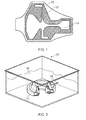
- Fig. 1 shows a cross sectional view through part of a forging 10 for a turbine disc of a gas turbine engine.
- the turbine disc is annular, having a shape shown in Fig. 2 .
- the forging 10 includes an initial workpiece profile 12 (also known as a "Condition of Supply", or COS) which is machined from a larger forging geometry 10.
- the workpiece 12 comprises a polygon having rectilinear sides.
- the workpiece 12 is further machined to form a final profile 14, which is the required shape of the turbine disc.
- the apparatus 15 contains sound conducting media such as water 16 which has a different refractive index than the workpiece 12 due to the lower speed of sound in water.
- An ultrasonic transducer 18 is used to perform ultrasonic testing on the workpiece 12 to determine whether parts of the final profile 14 which will be subject to high stresses include any defects.
- a defect in some locations, and particularly within high stress regions can be detected using a NDT technique such as ultrasonic testing. Consequently, it is desirable to be able to model the COS 12 to show that a defect in a given area can be detected, i.e. that a defect in the region of interest is detectable.
- Methods are known for simulating wave propagation in order to, for instance, model ultrasonic testing of an article.
- wave propagation is governed by a wave equation, which is a partial differential equation.
- Methods for solving this equation to simulate wave propagation across a domain of interest over time include methods such as the Finite Difference Method (FDM), and the Finite Element Method (FEM).
- FDM and FEM are known as "meshed" methods, and operate by discretising the problem domain into a plurality of sub-domains (or cells) known as a mesh.
- FDM Finite Difference Method
- FEM Finite Element Method
- a further wave based method comprises the Boundary Element Method (BEM).
- “Meshless” methods are also known, such as the Distributed Point Source Method (DPSM).
- DPSM Distributed Point Source Method
- the transducer face and interfaces are modelled as distributed point sources.
- the field variables of the ultrasonic wave are computed using Green's function. Based on Green's function, an arbitrary point in space will be influenced by the distributed points surrounded by it.
- Mesh free methods are preferable in some situations to meshed methods, as they have high computational efficiency.
- One type of Meshless method is known as a "Domain type” method.
- In Domain type methods the differential equations are approximated at the boundary as well as in the domain. Strong or weak formulations of the wave equation are used in the domain area, as this type of solution is well behaved in the domain.
- singularities i.e. errors in the computation
- a computer implemented method of determining the magnitude of a field variable of an energy wave at a predetermined time through a domain of interest comprising the steps of:
- N is the total number of master particles
- u m is the magnitude of a respective master particle
- f ( q 1) is an envelope function relating the magnitude of the virtual particle to the distance from the master particle in the direction of propagation of the master particle
- g ( q 2) is a smoothing function relating the magnitude of the virtual particle to the distance from the master particle normal to the direction of propagation of the master particle.
- the invention provides a method of determining wave propagation through a domain of interest by considering the position, magnitude and direction of the wave as the wave propagates through the domain, then only calculating the wave superposition aspect of the wave equation at the time of interest, without the requirement for calculating preceding time intervals. Consequently, the accuracy of the method is high, while the computational efficiency is also high, since the density of the virtual points does not determine the accuracy of the computation of the position, magnitude and direction of the wave fronts.
- the energy wave may comprise one of an acoustic wave such as an ultrasonic wave, an electromagnetic wave, a seismic wave
- the acoustic wave type may comprise one or more of a longitudinal waves, Sholte wave (interface waves), Rayleigh wave, shear wave, Stonley waves and Love wave.
- the supporting domain ⁇ m may comprise an ellipse having a first axis (q1) in the direction of propagation of the master particle, and a second axis (q2) in a direction normal to the propagation of the master particle.
- the length of the first axis q1 may comprise the wavelength of the energy wave, or may comprise the pulse length of the energy wave.
- the length of the second axis q2 may comprise the distance between neighbouring master particles.
- Each of the envelope function and the smoothing function may comprise any one of a Gaussian function, a linear smoothing function, and a moving average smoothing function.
- a method of determining the detectability of a defect within a supplied part out of which a final component is to be machined including the steps of:
- the method provides a method of simulating whether a defect can be detected by reflecting an energy wave from a defect, for a defect in a given location in a modelled domain of interest. Consequently, the method can be used to prove that any defects within the modelled domain of interest are detectable, thereby ensuring that defects do not go undetected during acceptance testing.
- Fig 3 shows steps in a method of determining the magnitude of a field variable of an energy wave propagating through a medium with respect to time in accordance with the present disclosure. Example results of this simulation are shown in figs. 4a to 4c .
- parameters of the process are defined. These parameters include the velocity of the energy wave in question in the simulated medium (for example, the speed of sound c in the medium where the wave is a sound wave), as well as the initial amplitude of the wave, and the initial wavelength of the energy wave. Where the medium is anisotropic (i.e. the speed of sound c is dependent on the direction of travel), this parameter may comprise a direction dependent function. Further parameters include a desired temporal resolution (i.e. the difference in time ⁇ t between time steps) and spatial resolution of master and virtual particles (which will be explained in greater detail hereafter).
- a problem domain is defined.
- the problem domain comprises a geometrical representation of an article such as the COS 12 to be investigated, comprising a shape bounded by walls.
- the shape may comprise a rectilinear shape, comprising straight lines to bound the domain of interest.
- a plurality of spaced points in the form of "virtual particles" are defined in the problem domain, in either a regular pattern as shown in step S2a, or in a randomly or pseudo-randomly generated irregular pattern, as shown in step S2b.
- Each virtual particle represents the magnitude of a desired field variable (such as material perturbation caused by the sound wave in the case of an ultrasonic sound wave) at the location within the problem domain of the respective virtual particle.
- each master particle represents field variables including at least the position, magnitude and direction of propagation of a wave front originating from a wave source.
- the master particles are located at the origin of the wave source and may have either a radial propagation or linear propagation direction depending on the type of wave being modelled (i.e. a radial or linear wave front).
- the example shown in figure 3 illustrates a radially propagating wave.
- the magnitude of the field variables is set as a series of parameters, in accordance with the wave source to be simulated. For example, where the simulation is of an ultrasonic wave, the field variables are set as those of the incoming wave from the transducer 18.
- Each master particle further comprises a supporting domain ⁇ m , which defines a region of the problem domain in which in which the magnitude of the master particle is to be distributed to the virtual particles.
- the supporting domain ⁇ m comprises an ellipse having a first axis q1 extending in a direction of propagation of the master particle, and a second axis q2 extending in a direction normal to the direction of propagation of the master particle.
- the length of the first axis q1 could comprise the wavelength of the energy wave (as defined in step S1 or calculated in accordance with step S6, described below). In the case of ultrasonic waves having a high frequency, the first axis could comprise the pulse length of the wave.
- N is the total number of master particles within the domain of interest
- f ( q 1) is an envelope function relating the magnitude of the virtual particle to the distance from the respective master particle in the direction of propagation of the respective master particle (i.e. axis q1)
- g ( q 2) is a smoothing function relating the magnitude of the virtual particle to the distance from the respective master particle normal to the direction of propagation of the master particle (i.e. axis q2).
- the product of f ( q 1) and g ( q 2) is referred to hereafter as the "joint distribution function".
- the above is calculated where v is a member of (i.e. located within) a supporting domain ⁇ m of a master particle.
- the envelope function could comprise any of a Gaussian function, a linear smoothing function, and a moving average smoothing function. Essentially, the envelope function represents the distribution of wave intensity through its wavelength, which in mode cases is essentially a Gaussian distribution.
- g q 2 e - x m - x v 2 2 * smoothing distance 2
- master particles' co-ordinate ( x m , y m ) and virtual particles' co-ordinate ( x v , y v ) are measured with respect to moving frame (q1, q2) of respective master particle.
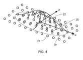
- Figure 4 shows a worked example of calculated magnitudes for virtual particles 20 within the supporting domain ⁇ m of a single master particle 22.
- the magnitude of the virtual particles is represented by the height of each particle above the plane of surrounding virtual particles 24, which lie outside the supporting region ⁇ m . as can be seen, the magnitude of the master particle 22 is distributed to the surrounding virtual particles 24 within the supporting region ⁇ m .
- step S4 the magnitudes of the virtual particles is reset to zero. Consequently, the memory requirements of the described method is reduced relative to prior methods, since the magnitudes of field variables in previous time steps does not have to be maintained in memory.
- the joint distribution function is applied to the virtual particles 20 within the supporting region ⁇ m for each master particle 22.
- the magnitude of the virtual particles 20 at each location is a function of the product of the envelope function and the smoothing function for the location of each virtual particle 20.
- step S6 the time is advanced by ⁇ t, and the new field variables for the master particles are calculated.
- These field variables include the position, magnitude and direction of propagation of the wave at the location of the respective master particle.
- the field variables are calculated by taking into account the effects of advection, spreading, reflection / refraction.
- the propagation could be determined in accordance with a geometrical method such as ray tracing method, or by a wave based method.
- ray tracing method the acoustic source is modelled as emitting a large number of rays (lines or particles) based on its directivity pattern. The number of rays in each direction is decided stochastically. The specular reflections are computed for each wall of the domain. Computational complexity of propagation depends on the number of walls present in the domain.
- Time of flight is the measure of standard time taken to propagate through the ray paths.
- TOF Time of flight
- the resultant ray path tends to bend. This phenomenon of the ray occurs difference in propagation velocity between the two material.
- the resulting TOF can be computed by applying slowness (S(x, y)) distribution to original TOF formula.
- TOF ⁇ L S x y d l
- the above method can be used to assess the detectability of a defect within the domain of interest by ultrasonic waves transmitted and detected by the transducer 18.
- the domain of interest COS 12 is defined, along with a wave source location corresponding to a candidate location of the transducer.
- a test defect 26 is introduced in an area of interest, and the following method is used to determine whether the defect 26 can be detected from the candidate transducer location.
- the propagation of the ultrasonic wave from the transducer 18 is computed using the above described ray tracing method (or another known computational method), by modelling the test defect 26 as a source of reflection within the domain.
- a time T at which reflect waves are returned to the transducer 18 is determined.
- the above described method of the first aspect of the invention is used to determine the amplitude of the signal at the time T at the candidate location of the transducer 18. This is compared with a predetermined transducer sensitivity - if the amplitude of the signal exceeds the predetermined transducer sensitivity, the defect is determined to be detectable from the candidate transducer location. If the signal does not exceed the predetermined transducer sensitivity, then the transducer is relocated to a new candidate location. If, after exhausting candidate transducer locations, the defect 26 cannot be detected from any accessible locations, then the defect 26 is deemed to be undetectable, and the geometry may have to be redesigned.
- the position of the wavefront could be determined using methods other than ray tracing, such as by the "Origami Method” outlined in applicant's co-pending GB patent application titled “Method of Determining Wave Propagation in a Medium”.
Landscapes
- Physics & Mathematics (AREA)
- General Physics & Mathematics (AREA)
- Immunology (AREA)
- Life Sciences & Earth Sciences (AREA)
- Pathology (AREA)
- General Health & Medical Sciences (AREA)
- Biochemistry (AREA)
- Analytical Chemistry (AREA)
- Chemical & Material Sciences (AREA)
- Health & Medical Sciences (AREA)
- Engineering & Computer Science (AREA)
- Signal Processing (AREA)
- Mathematical Analysis (AREA)
- Pure & Applied Mathematics (AREA)
- Mathematical Physics (AREA)
- Algebra (AREA)
- Mathematical Optimization (AREA)
- Acoustics & Sound (AREA)
- Investigating Or Analyzing Materials By The Use Of Ultrasonic Waves (AREA)
- Measurement Of Radiation (AREA)
Applications Claiming Priority (1)
| Application Number | Priority Date | Filing Date | Title |
|---|---|---|---|
| GBGB1420424.2A GB201420424D0 (en) | 2014-11-18 | 2014-11-18 | Method of determining the magnitude of a field variable of an energy wave |
Publications (3)
| Publication Number | Publication Date |
|---|---|
| EP3023779A2 true EP3023779A2 (de) | 2016-05-25 |
| EP3023779A3 EP3023779A3 (de) | 2016-07-13 |
| EP3023779B1 EP3023779B1 (de) | 2023-10-25 |
Family
ID=52248487
Family Applications (1)
| Application Number | Title | Priority Date | Filing Date |
|---|---|---|---|
| EP15192518.7A Active EP3023779B1 (de) | 2014-11-18 | 2015-11-02 | Verfahren zur bestimmung der grösse einer feldvariablen einer energiewelle |
Country Status (3)
| Country | Link |
|---|---|
| US (1) | US10444201B2 (de) |
| EP (1) | EP3023779B1 (de) |
| GB (1) | GB201420424D0 (de) |
Families Citing this family (1)
| Publication number | Priority date | Publication date | Assignee | Title |
|---|---|---|---|---|
| GB201420425D0 (en) * | 2014-11-18 | 2014-12-31 | Rolls Royce Plc | Method of determining wave propagation in a medium |
Family Cites Families (1)
| Publication number | Priority date | Publication date | Assignee | Title |
|---|---|---|---|---|
| US20020112540A1 (en) * | 2000-12-20 | 2002-08-22 | Schlumberger Technology Corporation | Acoustic method for estimating mechanical properties of a material and apparatus therefor |
-
2014
- 2014-11-18 GB GBGB1420424.2A patent/GB201420424D0/en not_active Ceased
-
2015
- 2015-11-02 US US14/929,817 patent/US10444201B2/en active Active
- 2015-11-02 EP EP15192518.7A patent/EP3023779B1/de active Active
Non-Patent Citations (1)
| Title |
|---|
| None * |
Also Published As
| Publication number | Publication date |
|---|---|
| EP3023779A3 (de) | 2016-07-13 |
| US10444201B2 (en) | 2019-10-15 |
| US20160139087A1 (en) | 2016-05-19 |
| EP3023779B1 (de) | 2023-10-25 |
| GB201420424D0 (en) | 2014-12-31 |
Similar Documents
| Publication | Publication Date | Title |
|---|---|---|
| Huthwaite et al. | High-resolution guided wave tomography | |
| Pettit et al. | Improved detection of rough defects for ultrasonic nondestructive evaluation inspections based on finite element modeling of elastic wave scattering | |
| Malyarenko et al. | Ultrasonic Lamb wave diffraction tomography | |
| Raghavan et al. | Guided-wave signal processing using chirplet matching pursuits and mode correlation for structural health monitoring | |
| Gao et al. | Enhanced wavefield imaging method for impact damage detection in composite laminates via laser-generated Lamb waves | |
| WO2020023967A1 (en) | Non-destructive concrete stress evaluation | |
| Rus et al. | Optimized damage detection of steel plates from noisy impact test | |
| Ferrand et al. | Modeling of ray paths of head waves on irregular interfaces in TOFD inspection for NDE | |
| Seidl et al. | Full waveform inversion for ultrasonic flaw identification | |
| Zhao et al. | A non-contact inspection method of tile debonding using tuned acoustic wave and laser doppler vibrometer | |
| Fromme et al. | Directivity of guided ultrasonic wave scattering at notches and cracks | |
| Xu et al. | Efficient generation of realistic guided wave signals for reliability estimation | |
| Zima | Guided ultrasonic wave technique for corrosion monitoring and thickness variability analysis | |
| Aggelis et al. | Numerical simulation of elastic waves for visualization of defects | |
| US6142019A (en) | Method of determining surface acoustic wave paths | |
| US20230314386A1 (en) | Method for characterizing a part through non-destructive inspection | |
| Gueudré et al. | Influence of the uncertainty of elastic constants on the modelling of ultrasound propagation through multi-pass austenitic welds. Impact on non-destructive testing | |
| Wilcox et al. | Progress towards a forward model of the complete acoustic emission process | |
| EP3023779B1 (de) | Verfahren zur bestimmung der grösse einer feldvariablen einer energiewelle | |
| Shiotani et al. | Hybrid elastic-wave CT with impact acoustics for single-side measurement in concrete structures | |
| Shi et al. | A time-domain finite element boundary integration method for ultrasonic nondestructive evaluation | |
| Wilcox et al. | Quantitative structural health monitoring using acoustic emission | |
| Phillips et al. | Simulating the ultrasonic scattering from complex surface-breaking defects with a three-dimensional hybrid model | |
| Sattarifar et al. | Frequency‐bounded Delay and Sum: A modified Damage Detection Method in thin‐walled Plates | |
| Langener et al. | Simulation of full-angle ultrasound process tomography with two-phase media using a ray-tracing technique |
Legal Events
| Date | Code | Title | Description |
|---|---|---|---|
| AK | Designated contracting states |
Kind code of ref document: A2 Designated state(s): AL AT BE BG CH CY CZ DE DK EE ES FI FR GB GR HR HU IE IS IT LI LT LU LV MC MK MT NL NO PL PT RO RS SE SI SK SM TR |
|
| AX | Request for extension of the european patent |
Extension state: BA ME |
|
| PUAI | Public reference made under article 153(3) epc to a published international application that has entered the european phase |
Free format text: ORIGINAL CODE: 0009012 |
|
| PUAL | Search report despatched |
Free format text: ORIGINAL CODE: 0009013 |
|
| RIC1 | Information provided on ipc code assigned before grant |
Ipc: G01N 29/44 20060101AFI20160525BHEP Ipc: G01N 29/04 20060101ALI20160525BHEP |
|
| AK | Designated contracting states |
Kind code of ref document: A3 Designated state(s): AL AT BE BG CH CY CZ DE DK EE ES FI FR GB GR HR HU IE IS IT LI LT LU LV MC MK MT NL NO PL PT RO RS SE SI SK SM TR |
|
| AX | Request for extension of the european patent |
Extension state: BA ME |
|
| RIC1 | Information provided on ipc code assigned before grant |
Ipc: G01N 29/44 20060101AFI20160606BHEP Ipc: G01N 29/04 20060101ALI20160606BHEP |
|
| 17P | Request for examination filed |
Effective date: 20160720 |
|
| RBV | Designated contracting states (corrected) |
Designated state(s): AL AT BE BG CH CY CZ DE DK EE ES FI FR GB GR HR HU IE IS IT LI LT LU LV MC MK MT NL NO PL PT RO RS SE SI SK SM TR |
|
| STAA | Information on the status of an ep patent application or granted ep patent |
Free format text: STATUS: EXAMINATION IS IN PROGRESS |
|
| 17Q | First examination report despatched |
Effective date: 20191024 |
|
| RAP1 | Party data changed (applicant data changed or rights of an application transferred) |
Owner name: ROLLS-ROYCE PLC |
|
| GRAP | Despatch of communication of intention to grant a patent |
Free format text: ORIGINAL CODE: EPIDOSNIGR1 |
|
| STAA | Information on the status of an ep patent application or granted ep patent |
Free format text: STATUS: GRANT OF PATENT IS INTENDED |
|
| INTG | Intention to grant announced |
Effective date: 20230414 |
|
| P01 | Opt-out of the competence of the unified patent court (upc) registered |
Effective date: 20230528 |
|
| GRAJ | Information related to disapproval of communication of intention to grant by the applicant or resumption of examination proceedings by the epo deleted |
Free format text: ORIGINAL CODE: EPIDOSDIGR1 |
|
| STAA | Information on the status of an ep patent application or granted ep patent |
Free format text: STATUS: EXAMINATION IS IN PROGRESS |
|
| INTC | Intention to grant announced (deleted) | ||
| GRAP | Despatch of communication of intention to grant a patent |
Free format text: ORIGINAL CODE: EPIDOSNIGR1 |
|
| STAA | Information on the status of an ep patent application or granted ep patent |
Free format text: STATUS: GRANT OF PATENT IS INTENDED |
|
| GRAS | Grant fee paid |
Free format text: ORIGINAL CODE: EPIDOSNIGR3 |
|
| GRAA | (expected) grant |
Free format text: ORIGINAL CODE: 0009210 |
|
| STAA | Information on the status of an ep patent application or granted ep patent |
Free format text: STATUS: THE PATENT HAS BEEN GRANTED |
|
| INTG | Intention to grant announced |
Effective date: 20230911 |
|
| AK | Designated contracting states |
Kind code of ref document: B1 Designated state(s): AL AT BE BG CH CY CZ DE DK EE ES FI FR GB GR HR HU IE IS IT LI LT LU LV MC MK MT NL NO PL PT RO RS SE SI SK SM TR |
|
| REG | Reference to a national code |
Ref country code: GB Ref legal event code: FG4D |
|
| REG | Reference to a national code |
Ref country code: CH Ref legal event code: EP |
|
| REG | Reference to a national code |
Ref country code: DE Ref legal event code: R096 Ref document number: 602015086195 Country of ref document: DE |
|
| REG | Reference to a national code |
Ref country code: IE Ref legal event code: FG4D |
|
| REG | Reference to a national code |
Ref country code: LT Ref legal event code: MG9D |
|
| REG | Reference to a national code |
Ref country code: NL Ref legal event code: MP Effective date: 20231025 |
|
| REG | Reference to a national code |
Ref country code: AT Ref legal event code: MK05 Ref document number: 1625150 Country of ref document: AT Kind code of ref document: T Effective date: 20231025 |
|
| PG25 | Lapsed in a contracting state [announced via postgrant information from national office to epo] |
Ref country code: NL Free format text: LAPSE BECAUSE OF FAILURE TO SUBMIT A TRANSLATION OF THE DESCRIPTION OR TO PAY THE FEE WITHIN THE PRESCRIBED TIME-LIMIT Effective date: 20231025 |
|
| PG25 | Lapsed in a contracting state [announced via postgrant information from national office to epo] |
Ref country code: GR Free format text: LAPSE BECAUSE OF FAILURE TO SUBMIT A TRANSLATION OF THE DESCRIPTION OR TO PAY THE FEE WITHIN THE PRESCRIBED TIME-LIMIT Effective date: 20240126 |
|
| PG25 | Lapsed in a contracting state [announced via postgrant information from national office to epo] |
Ref country code: IS Free format text: LAPSE BECAUSE OF FAILURE TO SUBMIT A TRANSLATION OF THE DESCRIPTION OR TO PAY THE FEE WITHIN THE PRESCRIBED TIME-LIMIT Effective date: 20240225 |
|
| PG25 | Lapsed in a contracting state [announced via postgrant information from national office to epo] |
Ref country code: LT Free format text: LAPSE BECAUSE OF FAILURE TO SUBMIT A TRANSLATION OF THE DESCRIPTION OR TO PAY THE FEE WITHIN THE PRESCRIBED TIME-LIMIT Effective date: 20231025 |
|
| PG25 | Lapsed in a contracting state [announced via postgrant information from national office to epo] |
Ref country code: AT Free format text: LAPSE BECAUSE OF FAILURE TO SUBMIT A TRANSLATION OF THE DESCRIPTION OR TO PAY THE FEE WITHIN THE PRESCRIBED TIME-LIMIT Effective date: 20231025 |
|
| PG25 | Lapsed in a contracting state [announced via postgrant information from national office to epo] |
Ref country code: ES Free format text: LAPSE BECAUSE OF FAILURE TO SUBMIT A TRANSLATION OF THE DESCRIPTION OR TO PAY THE FEE WITHIN THE PRESCRIBED TIME-LIMIT Effective date: 20231025 |
|
| PG25 | Lapsed in a contracting state [announced via postgrant information from national office to epo] |
Ref country code: LT Free format text: LAPSE BECAUSE OF FAILURE TO SUBMIT A TRANSLATION OF THE DESCRIPTION OR TO PAY THE FEE WITHIN THE PRESCRIBED TIME-LIMIT Effective date: 20231025 Ref country code: IS Free format text: LAPSE BECAUSE OF FAILURE TO SUBMIT A TRANSLATION OF THE DESCRIPTION OR TO PAY THE FEE WITHIN THE PRESCRIBED TIME-LIMIT Effective date: 20240225 Ref country code: GR Free format text: LAPSE BECAUSE OF FAILURE TO SUBMIT A TRANSLATION OF THE DESCRIPTION OR TO PAY THE FEE WITHIN THE PRESCRIBED TIME-LIMIT Effective date: 20240126 Ref country code: ES Free format text: LAPSE BECAUSE OF FAILURE TO SUBMIT A TRANSLATION OF THE DESCRIPTION OR TO PAY THE FEE WITHIN THE PRESCRIBED TIME-LIMIT Effective date: 20231025 Ref country code: BG Free format text: LAPSE BECAUSE OF FAILURE TO SUBMIT A TRANSLATION OF THE DESCRIPTION OR TO PAY THE FEE WITHIN THE PRESCRIBED TIME-LIMIT Effective date: 20240125 Ref country code: AT Free format text: LAPSE BECAUSE OF FAILURE TO SUBMIT A TRANSLATION OF THE DESCRIPTION OR TO PAY THE FEE WITHIN THE PRESCRIBED TIME-LIMIT Effective date: 20231025 Ref country code: PT Free format text: LAPSE BECAUSE OF FAILURE TO SUBMIT A TRANSLATION OF THE DESCRIPTION OR TO PAY THE FEE WITHIN THE PRESCRIBED TIME-LIMIT Effective date: 20240226 |
|
| PG25 | Lapsed in a contracting state [announced via postgrant information from national office to epo] |
Ref country code: SE Free format text: LAPSE BECAUSE OF FAILURE TO SUBMIT A TRANSLATION OF THE DESCRIPTION OR TO PAY THE FEE WITHIN THE PRESCRIBED TIME-LIMIT Effective date: 20231025 Ref country code: RS Free format text: LAPSE BECAUSE OF FAILURE TO SUBMIT A TRANSLATION OF THE DESCRIPTION OR TO PAY THE FEE WITHIN THE PRESCRIBED TIME-LIMIT Effective date: 20231025 Ref country code: PL Free format text: LAPSE BECAUSE OF FAILURE TO SUBMIT A TRANSLATION OF THE DESCRIPTION OR TO PAY THE FEE WITHIN THE PRESCRIBED TIME-LIMIT Effective date: 20231025 Ref country code: NO Free format text: LAPSE BECAUSE OF FAILURE TO SUBMIT A TRANSLATION OF THE DESCRIPTION OR TO PAY THE FEE WITHIN THE PRESCRIBED TIME-LIMIT Effective date: 20240125 Ref country code: LV Free format text: LAPSE BECAUSE OF FAILURE TO SUBMIT A TRANSLATION OF THE DESCRIPTION OR TO PAY THE FEE WITHIN THE PRESCRIBED TIME-LIMIT Effective date: 20231025 Ref country code: HR Free format text: LAPSE BECAUSE OF FAILURE TO SUBMIT A TRANSLATION OF THE DESCRIPTION OR TO PAY THE FEE WITHIN THE PRESCRIBED TIME-LIMIT Effective date: 20231025 |
|
| REG | Reference to a national code |
Ref country code: CH Ref legal event code: PL |
|
| PG25 | Lapsed in a contracting state [announced via postgrant information from national office to epo] |
Ref country code: DK Free format text: LAPSE BECAUSE OF FAILURE TO SUBMIT A TRANSLATION OF THE DESCRIPTION OR TO PAY THE FEE WITHIN THE PRESCRIBED TIME-LIMIT Effective date: 20231025 |
|
| PG25 | Lapsed in a contracting state [announced via postgrant information from national office to epo] |
Ref country code: LU Free format text: LAPSE BECAUSE OF NON-PAYMENT OF DUE FEES Effective date: 20231102 |
|
| PG25 | Lapsed in a contracting state [announced via postgrant information from national office to epo] |
Ref country code: CH Free format text: LAPSE BECAUSE OF NON-PAYMENT OF DUE FEES Effective date: 20231130 |
|
| PG25 | Lapsed in a contracting state [announced via postgrant information from national office to epo] |
Ref country code: CZ Free format text: LAPSE BECAUSE OF FAILURE TO SUBMIT A TRANSLATION OF THE DESCRIPTION OR TO PAY THE FEE WITHIN THE PRESCRIBED TIME-LIMIT Effective date: 20231025 |
|
| REG | Reference to a national code |
Ref country code: DE Ref legal event code: R097 Ref document number: 602015086195 Country of ref document: DE |
|
| PG25 | Lapsed in a contracting state [announced via postgrant information from national office to epo] |
Ref country code: SK Free format text: LAPSE BECAUSE OF FAILURE TO SUBMIT A TRANSLATION OF THE DESCRIPTION OR TO PAY THE FEE WITHIN THE PRESCRIBED TIME-LIMIT Effective date: 20231025 |
|
| PG25 | Lapsed in a contracting state [announced via postgrant information from national office to epo] |
Ref country code: SM Free format text: LAPSE BECAUSE OF FAILURE TO SUBMIT A TRANSLATION OF THE DESCRIPTION OR TO PAY THE FEE WITHIN THE PRESCRIBED TIME-LIMIT Effective date: 20231025 Ref country code: SK Free format text: LAPSE BECAUSE OF FAILURE TO SUBMIT A TRANSLATION OF THE DESCRIPTION OR TO PAY THE FEE WITHIN THE PRESCRIBED TIME-LIMIT Effective date: 20231025 Ref country code: RO Free format text: LAPSE BECAUSE OF FAILURE TO SUBMIT A TRANSLATION OF THE DESCRIPTION OR TO PAY THE FEE WITHIN THE PRESCRIBED TIME-LIMIT Effective date: 20231025 Ref country code: LU Free format text: LAPSE BECAUSE OF NON-PAYMENT OF DUE FEES Effective date: 20231102 Ref country code: IT Free format text: LAPSE BECAUSE OF FAILURE TO SUBMIT A TRANSLATION OF THE DESCRIPTION OR TO PAY THE FEE WITHIN THE PRESCRIBED TIME-LIMIT Effective date: 20231025 Ref country code: EE Free format text: LAPSE BECAUSE OF FAILURE TO SUBMIT A TRANSLATION OF THE DESCRIPTION OR TO PAY THE FEE WITHIN THE PRESCRIBED TIME-LIMIT Effective date: 20231025 Ref country code: DK Free format text: LAPSE BECAUSE OF FAILURE TO SUBMIT A TRANSLATION OF THE DESCRIPTION OR TO PAY THE FEE WITHIN THE PRESCRIBED TIME-LIMIT Effective date: 20231025 Ref country code: CZ Free format text: LAPSE BECAUSE OF FAILURE TO SUBMIT A TRANSLATION OF THE DESCRIPTION OR TO PAY THE FEE WITHIN THE PRESCRIBED TIME-LIMIT Effective date: 20231025 Ref country code: CH Free format text: LAPSE BECAUSE OF NON-PAYMENT OF DUE FEES Effective date: 20231130 |
|
| REG | Reference to a national code |
Ref country code: BE Ref legal event code: MM Effective date: 20231130 |
|
| PG25 | Lapsed in a contracting state [announced via postgrant information from national office to epo] |
Ref country code: MC Free format text: LAPSE BECAUSE OF FAILURE TO SUBMIT A TRANSLATION OF THE DESCRIPTION OR TO PAY THE FEE WITHIN THE PRESCRIBED TIME-LIMIT Effective date: 20231025 |
|
| PG25 | Lapsed in a contracting state [announced via postgrant information from national office to epo] |
Ref country code: MC Free format text: LAPSE BECAUSE OF FAILURE TO SUBMIT A TRANSLATION OF THE DESCRIPTION OR TO PAY THE FEE WITHIN THE PRESCRIBED TIME-LIMIT Effective date: 20231025 |
|
| PLBE | No opposition filed within time limit |
Free format text: ORIGINAL CODE: 0009261 |
|
| STAA | Information on the status of an ep patent application or granted ep patent |
Free format text: STATUS: NO OPPOSITION FILED WITHIN TIME LIMIT |
|
| REG | Reference to a national code |
Ref country code: IE Ref legal event code: MM4A |
|
| 26N | No opposition filed |
Effective date: 20240726 |
|
| PG25 | Lapsed in a contracting state [announced via postgrant information from national office to epo] |
Ref country code: IE Free format text: LAPSE BECAUSE OF NON-PAYMENT OF DUE FEES Effective date: 20231102 |
|
| PG25 | Lapsed in a contracting state [announced via postgrant information from national office to epo] |
Ref country code: BE Free format text: LAPSE BECAUSE OF NON-PAYMENT OF DUE FEES Effective date: 20231130 |
|
| PG25 | Lapsed in a contracting state [announced via postgrant information from national office to epo] |
Ref country code: SI Free format text: LAPSE BECAUSE OF FAILURE TO SUBMIT A TRANSLATION OF THE DESCRIPTION OR TO PAY THE FEE WITHIN THE PRESCRIBED TIME-LIMIT Effective date: 20231025 |
|
| PG25 | Lapsed in a contracting state [announced via postgrant information from national office to epo] |
Ref country code: SI Free format text: LAPSE BECAUSE OF FAILURE TO SUBMIT A TRANSLATION OF THE DESCRIPTION OR TO PAY THE FEE WITHIN THE PRESCRIBED TIME-LIMIT Effective date: 20231025 Ref country code: IE Free format text: LAPSE BECAUSE OF NON-PAYMENT OF DUE FEES Effective date: 20231102 Ref country code: BE Free format text: LAPSE BECAUSE OF NON-PAYMENT OF DUE FEES Effective date: 20231130 |
|
| PG25 | Lapsed in a contracting state [announced via postgrant information from national office to epo] |
Ref country code: FI Free format text: LAPSE BECAUSE OF FAILURE TO SUBMIT A TRANSLATION OF THE DESCRIPTION OR TO PAY THE FEE WITHIN THE PRESCRIBED TIME-LIMIT Effective date: 20231025 |
|
| PG25 | Lapsed in a contracting state [announced via postgrant information from national office to epo] |
Ref country code: CY Free format text: LAPSE BECAUSE OF FAILURE TO SUBMIT A TRANSLATION OF THE DESCRIPTION OR TO PAY THE FEE WITHIN THE PRESCRIBED TIME-LIMIT; INVALID AB INITIO Effective date: 20151102 |
|
| PG25 | Lapsed in a contracting state [announced via postgrant information from national office to epo] |
Ref country code: HU Free format text: LAPSE BECAUSE OF FAILURE TO SUBMIT A TRANSLATION OF THE DESCRIPTION OR TO PAY THE FEE WITHIN THE PRESCRIBED TIME-LIMIT; INVALID AB INITIO Effective date: 20151102 |
|
| PG25 | Lapsed in a contracting state [announced via postgrant information from national office to epo] |
Ref country code: TR Free format text: LAPSE BECAUSE OF FAILURE TO SUBMIT A TRANSLATION OF THE DESCRIPTION OR TO PAY THE FEE WITHIN THE PRESCRIBED TIME-LIMIT Effective date: 20231025 |
|
| PGFP | Annual fee paid to national office [announced via postgrant information from national office to epo] |
Ref country code: DE Payment date: 20251126 Year of fee payment: 11 |
|
| PGFP | Annual fee paid to national office [announced via postgrant information from national office to epo] |
Ref country code: GB Payment date: 20251125 Year of fee payment: 11 |
|
| PGFP | Annual fee paid to national office [announced via postgrant information from national office to epo] |
Ref country code: FR Payment date: 20251124 Year of fee payment: 11 |