EP3023757A1 - Pyrometric detection device, method for calibrating the same, and apparatus for producing three-dimensional work pieces - Google Patents
Pyrometric detection device, method for calibrating the same, and apparatus for producing three-dimensional work pieces Download PDFInfo
- Publication number
- EP3023757A1 EP3023757A1 EP14194378.7A EP14194378A EP3023757A1 EP 3023757 A1 EP3023757 A1 EP 3023757A1 EP 14194378 A EP14194378 A EP 14194378A EP 3023757 A1 EP3023757 A1 EP 3023757A1
- Authority
- EP
- European Patent Office
- Prior art keywords
- light
- pyrometric
- light guides
- detection
- substrate
- Prior art date
- Legal status (The legal status is an assumption and is not a legal conclusion. Google has not performed a legal analysis and makes no representation as to the accuracy of the status listed.)
- Granted
Links
- 238000001514 detection method Methods 0.000 title claims abstract description 108
- 238000000034 method Methods 0.000 title claims description 17
- 239000000758 substrate Substances 0.000 claims abstract description 57
- 230000005855 radiation Effects 0.000 claims abstract description 42
- 230000008878 coupling Effects 0.000 claims abstract description 7
- 238000010168 coupling process Methods 0.000 claims abstract description 7
- 238000005859 coupling reaction Methods 0.000 claims abstract description 7
- 239000000843 powder Substances 0.000 claims description 26
- 239000002994 raw material Substances 0.000 claims description 16
- 239000011159 matrix material Substances 0.000 claims description 11
- 239000002245 particle Substances 0.000 claims description 7
- 230000001678 irradiating effect Effects 0.000 claims description 6
- 239000003365 glass fiber Substances 0.000 claims description 3
- 238000005259 measurement Methods 0.000 claims description 3
- 230000003287 optical effect Effects 0.000 description 35
- 238000002844 melting Methods 0.000 description 8
- 230000008018 melting Effects 0.000 description 8
- 230000008569 process Effects 0.000 description 6
- 238000005245 sintering Methods 0.000 description 5
- 230000004927 fusion Effects 0.000 description 4
- 229910052782 aluminium Inorganic materials 0.000 description 3
- XAGFODPZIPBFFR-UHFFFAOYSA-N aluminium Chemical compound [Al] XAGFODPZIPBFFR-UHFFFAOYSA-N 0.000 description 3
- 230000001419 dependent effect Effects 0.000 description 3
- 239000007789 gas Substances 0.000 description 3
- 230000005670 electromagnetic radiation Effects 0.000 description 2
- 239000003292 glue Substances 0.000 description 2
- 238000004519 manufacturing process Methods 0.000 description 2
- 229910052751 metal Inorganic materials 0.000 description 2
- 239000002184 metal Substances 0.000 description 2
- 239000011347 resin Substances 0.000 description 2
- 229920005989 resin Polymers 0.000 description 2
- 230000005457 Black-body radiation Effects 0.000 description 1
- 239000000654 additive Substances 0.000 description 1
- 230000000996 additive effect Effects 0.000 description 1
- 239000004411 aluminium Substances 0.000 description 1
- 230000000903 blocking effect Effects 0.000 description 1
- 239000000919 ceramic Substances 0.000 description 1
- 238000010276 construction Methods 0.000 description 1
- 238000011156 evaluation Methods 0.000 description 1
- 238000010438 heat treatment Methods 0.000 description 1
- 239000011261 inert gas Substances 0.000 description 1
- 238000013532 laser treatment Methods 0.000 description 1
- 238000012806 monitoring device Methods 0.000 description 1
- 238000012544 monitoring process Methods 0.000 description 1
- 239000013307 optical fiber Substances 0.000 description 1
- 230000000149 penetrating effect Effects 0.000 description 1
- 230000000704 physical effect Effects 0.000 description 1
Images

Classifications
-
- G—PHYSICS
- G01—MEASURING; TESTING
- G01J—MEASUREMENT OF INTENSITY, VELOCITY, SPECTRAL CONTENT, POLARISATION, PHASE OR PULSE CHARACTERISTICS OF INFRARED, VISIBLE OR ULTRAVIOLET LIGHT; COLORIMETRY; RADIATION PYROMETRY
- G01J5/00—Radiation pyrometry, e.g. infrared or optical thermometry
- G01J5/0003—Radiation pyrometry, e.g. infrared or optical thermometry for sensing the radiant heat transfer of samples, e.g. emittance meter
-
- G—PHYSICS
- G01—MEASURING; TESTING
- G01J—MEASUREMENT OF INTENSITY, VELOCITY, SPECTRAL CONTENT, POLARISATION, PHASE OR PULSE CHARACTERISTICS OF INFRARED, VISIBLE OR ULTRAVIOLET LIGHT; COLORIMETRY; RADIATION PYROMETRY
- G01J5/00—Radiation pyrometry, e.g. infrared or optical thermometry
- G01J5/02—Constructional details
- G01J5/08—Optical arrangements
- G01J5/0818—Waveguides
- G01J5/0821—Optical fibres
-
- B—PERFORMING OPERATIONS; TRANSPORTING
- B22—CASTING; POWDER METALLURGY
- B22F—WORKING METALLIC POWDER; MANUFACTURE OF ARTICLES FROM METALLIC POWDER; MAKING METALLIC POWDER; APPARATUS OR DEVICES SPECIALLY ADAPTED FOR METALLIC POWDER
- B22F12/00—Apparatus or devices specially adapted for additive manufacturing; Auxiliary means for additive manufacturing; Combinations of additive manufacturing apparatus or devices with other processing apparatus or devices
- B22F12/90—Means for process control, e.g. cameras or sensors
-
- B—PERFORMING OPERATIONS; TRANSPORTING
- B29—WORKING OF PLASTICS; WORKING OF SUBSTANCES IN A PLASTIC STATE IN GENERAL
- B29C—SHAPING OR JOINING OF PLASTICS; SHAPING OF MATERIAL IN A PLASTIC STATE, NOT OTHERWISE PROVIDED FOR; AFTER-TREATMENT OF THE SHAPED PRODUCTS, e.g. REPAIRING
- B29C64/00—Additive manufacturing, i.e. manufacturing of three-dimensional [3D] objects by additive deposition, additive agglomeration or additive layering, e.g. by 3D printing, stereolithography or selective laser sintering
- B29C64/20—Apparatus for additive manufacturing; Details thereof or accessories therefor
- B29C64/264—Arrangements for irradiation
-
- B—PERFORMING OPERATIONS; TRANSPORTING
- B29—WORKING OF PLASTICS; WORKING OF SUBSTANCES IN A PLASTIC STATE IN GENERAL
- B29C—SHAPING OR JOINING OF PLASTICS; SHAPING OF MATERIAL IN A PLASTIC STATE, NOT OTHERWISE PROVIDED FOR; AFTER-TREATMENT OF THE SHAPED PRODUCTS, e.g. REPAIRING
- B29C64/00—Additive manufacturing, i.e. manufacturing of three-dimensional [3D] objects by additive deposition, additive agglomeration or additive layering, e.g. by 3D printing, stereolithography or selective laser sintering
- B29C64/30—Auxiliary operations or equipment
- B29C64/386—Data acquisition or data processing for additive manufacturing
- B29C64/393—Data acquisition or data processing for additive manufacturing for controlling or regulating additive manufacturing processes
-
- B—PERFORMING OPERATIONS; TRANSPORTING
- B33—ADDITIVE MANUFACTURING TECHNOLOGY
- B33Y—ADDITIVE MANUFACTURING, i.e. MANUFACTURING OF THREE-DIMENSIONAL [3-D] OBJECTS BY ADDITIVE DEPOSITION, ADDITIVE AGGLOMERATION OR ADDITIVE LAYERING, e.g. BY 3-D PRINTING, STEREOLITHOGRAPHY OR SELECTIVE LASER SINTERING
- B33Y30/00—Apparatus for additive manufacturing; Details thereof or accessories therefor
-
- B—PERFORMING OPERATIONS; TRANSPORTING
- B33—ADDITIVE MANUFACTURING TECHNOLOGY
- B33Y—ADDITIVE MANUFACTURING, i.e. MANUFACTURING OF THREE-DIMENSIONAL [3-D] OBJECTS BY ADDITIVE DEPOSITION, ADDITIVE AGGLOMERATION OR ADDITIVE LAYERING, e.g. BY 3-D PRINTING, STEREOLITHOGRAPHY OR SELECTIVE LASER SINTERING
- B33Y50/00—Data acquisition or data processing for additive manufacturing
- B33Y50/02—Data acquisition or data processing for additive manufacturing for controlling or regulating additive manufacturing processes
-
- G—PHYSICS
- G01—MEASURING; TESTING
- G01J—MEASUREMENT OF INTENSITY, VELOCITY, SPECTRAL CONTENT, POLARISATION, PHASE OR PULSE CHARACTERISTICS OF INFRARED, VISIBLE OR ULTRAVIOLET LIGHT; COLORIMETRY; RADIATION PYROMETRY
- G01J5/00—Radiation pyrometry, e.g. infrared or optical thermometry
- G01J5/0037—Radiation pyrometry, e.g. infrared or optical thermometry for sensing the heat emitted by liquids
- G01J5/004—Radiation pyrometry, e.g. infrared or optical thermometry for sensing the heat emitted by liquids by molten metals
-
- G—PHYSICS
- G01—MEASURING; TESTING
- G01J—MEASUREMENT OF INTENSITY, VELOCITY, SPECTRAL CONTENT, POLARISATION, PHASE OR PULSE CHARACTERISTICS OF INFRARED, VISIBLE OR ULTRAVIOLET LIGHT; COLORIMETRY; RADIATION PYROMETRY
- G01J5/00—Radiation pyrometry, e.g. infrared or optical thermometry
- G01J5/02—Constructional details
- G01J5/04—Casings
- G01J5/047—Mobile mounting; Scanning arrangements
-
- G—PHYSICS
- G01—MEASURING; TESTING
- G01J—MEASUREMENT OF INTENSITY, VELOCITY, SPECTRAL CONTENT, POLARISATION, PHASE OR PULSE CHARACTERISTICS OF INFRARED, VISIBLE OR ULTRAVIOLET LIGHT; COLORIMETRY; RADIATION PYROMETRY
- G01J5/00—Radiation pyrometry, e.g. infrared or optical thermometry
- G01J5/02—Constructional details
- G01J5/07—Arrangements for adjusting the solid angle of collected radiation, e.g. adjusting or orienting field of view, tracking position or encoding angular position
-
- G—PHYSICS
- G01—MEASURING; TESTING
- G01J—MEASUREMENT OF INTENSITY, VELOCITY, SPECTRAL CONTENT, POLARISATION, PHASE OR PULSE CHARACTERISTICS OF INFRARED, VISIBLE OR ULTRAVIOLET LIGHT; COLORIMETRY; RADIATION PYROMETRY
- G01J5/00—Radiation pyrometry, e.g. infrared or optical thermometry
- G01J5/02—Constructional details
- G01J5/08—Optical arrangements
- G01J5/0808—Convex mirrors
-
- G—PHYSICS
- G01—MEASURING; TESTING
- G01J—MEASUREMENT OF INTENSITY, VELOCITY, SPECTRAL CONTENT, POLARISATION, PHASE OR PULSE CHARACTERISTICS OF INFRARED, VISIBLE OR ULTRAVIOLET LIGHT; COLORIMETRY; RADIATION PYROMETRY
- G01J5/00—Radiation pyrometry, e.g. infrared or optical thermometry
- G01J5/02—Constructional details
- G01J5/08—Optical arrangements
- G01J5/0896—Optical arrangements using a light source, e.g. for illuminating a surface
-
- G—PHYSICS
- G01—MEASURING; TESTING
- G01J—MEASUREMENT OF INTENSITY, VELOCITY, SPECTRAL CONTENT, POLARISATION, PHASE OR PULSE CHARACTERISTICS OF INFRARED, VISIBLE OR ULTRAVIOLET LIGHT; COLORIMETRY; RADIATION PYROMETRY
- G01J5/00—Radiation pyrometry, e.g. infrared or optical thermometry
- G01J5/52—Radiation pyrometry, e.g. infrared or optical thermometry using comparison with reference sources, e.g. disappearing-filament pyrometer
- G01J5/53—Reference sources, e.g. standard lamps; Black bodies
-
- G—PHYSICS
- G01—MEASURING; TESTING
- G01J—MEASUREMENT OF INTENSITY, VELOCITY, SPECTRAL CONTENT, POLARISATION, PHASE OR PULSE CHARACTERISTICS OF INFRARED, VISIBLE OR ULTRAVIOLET LIGHT; COLORIMETRY; RADIATION PYROMETRY
- G01J5/00—Radiation pyrometry, e.g. infrared or optical thermometry
- G01J5/60—Radiation pyrometry, e.g. infrared or optical thermometry using determination of colour temperature
- G01J5/602—Radiation pyrometry, e.g. infrared or optical thermometry using determination of colour temperature using selective, monochromatic or bandpass filtering
-
- G—PHYSICS
- G01—MEASURING; TESTING
- G01J—MEASUREMENT OF INTENSITY, VELOCITY, SPECTRAL CONTENT, POLARISATION, PHASE OR PULSE CHARACTERISTICS OF INFRARED, VISIBLE OR ULTRAVIOLET LIGHT; COLORIMETRY; RADIATION PYROMETRY
- G01J5/00—Radiation pyrometry, e.g. infrared or optical thermometry
- G01J5/80—Calibration
- G01J5/806—Calibration by correcting for reflection of the emitter radiation
-
- B—PERFORMING OPERATIONS; TRANSPORTING
- B22—CASTING; POWDER METALLURGY
- B22F—WORKING METALLIC POWDER; MANUFACTURE OF ARTICLES FROM METALLIC POWDER; MAKING METALLIC POWDER; APPARATUS OR DEVICES SPECIALLY ADAPTED FOR METALLIC POWDER
- B22F12/00—Apparatus or devices specially adapted for additive manufacturing; Auxiliary means for additive manufacturing; Combinations of additive manufacturing apparatus or devices with other processing apparatus or devices
- B22F12/40—Radiation means
- B22F12/41—Radiation means characterised by the type, e.g. laser or electron beam
-
- B—PERFORMING OPERATIONS; TRANSPORTING
- B22—CASTING; POWDER METALLURGY
- B22F—WORKING METALLIC POWDER; MANUFACTURE OF ARTICLES FROM METALLIC POWDER; MAKING METALLIC POWDER; APPARATUS OR DEVICES SPECIALLY ADAPTED FOR METALLIC POWDER
- B22F12/00—Apparatus or devices specially adapted for additive manufacturing; Auxiliary means for additive manufacturing; Combinations of additive manufacturing apparatus or devices with other processing apparatus or devices
- B22F12/40—Radiation means
- B22F12/44—Radiation means characterised by the configuration of the radiation means
-
- B—PERFORMING OPERATIONS; TRANSPORTING
- B29—WORKING OF PLASTICS; WORKING OF SUBSTANCES IN A PLASTIC STATE IN GENERAL
- B29C—SHAPING OR JOINING OF PLASTICS; SHAPING OF MATERIAL IN A PLASTIC STATE, NOT OTHERWISE PROVIDED FOR; AFTER-TREATMENT OF THE SHAPED PRODUCTS, e.g. REPAIRING
- B29C64/00—Additive manufacturing, i.e. manufacturing of three-dimensional [3D] objects by additive deposition, additive agglomeration or additive layering, e.g. by 3D printing, stereolithography or selective laser sintering
- B29C64/10—Processes of additive manufacturing
- B29C64/141—Processes of additive manufacturing using only solid materials
- B29C64/153—Processes of additive manufacturing using only solid materials using layers of powder being selectively joined, e.g. by selective laser sintering or melting
-
- Y—GENERAL TAGGING OF NEW TECHNOLOGICAL DEVELOPMENTS; GENERAL TAGGING OF CROSS-SECTIONAL TECHNOLOGIES SPANNING OVER SEVERAL SECTIONS OF THE IPC; TECHNICAL SUBJECTS COVERED BY FORMER USPC CROSS-REFERENCE ART COLLECTIONS [XRACs] AND DIGESTS
- Y02—TECHNOLOGIES OR APPLICATIONS FOR MITIGATION OR ADAPTATION AGAINST CLIMATE CHANGE
- Y02P—CLIMATE CHANGE MITIGATION TECHNOLOGIES IN THE PRODUCTION OR PROCESSING OF GOODS
- Y02P10/00—Technologies related to metal processing
- Y02P10/25—Process efficiency
Definitions
- the present invention relates to a pyrometric detection device and a method for calibrating the same.
- the present invention further relates to an apparatus for producing three-dimensional work pieces.
- Powder bed fusion is an additive layering process by which pulverulent, in particular metallic and/or ceramic raw materials can be processed to three-dimensional work pieces of complex shapes.
- a raw material powder layer is applied onto a carrier and subjected to a laser radiation in a site selective manner in dependence on the desired geometry of the work piece that is to be produced.
- the laser radiation penetrating into the powder layer causes heating and consequently melting or sintering of the raw material powder particles.
- Further raw material powder layers are then applied successively to the layer on the carrier that has already been subjected to laser treatment, until the work piece has the desired shape and size.
- Powder bed fusion can be used in particular for the production of prototypes, tools, replacement parts or medical prostheses, such as, for example, dental or orthopaedic prostheses, on the basis of CAD data.
- laser irradiation other electromagnetic or particle radiation, such as electron irradiation, might be used for melting or sintering of the raw material powder particles.
- the melting or sintering conditions at the irradiation spot may be monitored during production by a monitoring device.
- the invention is directed to the object of providing a pyrometric detection device and a method for calibrating the same, which allow a precise monitoring of a building process for generating a three-dimensional work piece by irradiating layers of raw material powder with electromagnetic or particle radiation.
- the invention is further directed to the object of providing an apparatus for producing three-dimensional work pieces.
- a pyrometric detection device for use in an apparatus for producing three-dimensional work pieces comprises a pyrometric detecting unit configured to receive thermal radiation emitted at different points of a detection plane in a detection direction and a calibration device comprising a substrate and a plurality of light guides each having a first end for coupling light into the light guide and a second end for emitting light from the light guide, the second end being fixed to the substrate.
- the substrate is adapted to be removably arranged relative to the pyrometric detecting unit in such a manner that the second ends of the plurality of light guides are arranged in the detection plane and emit light in the detection direction, in a calibration state of the pyrometric detection device.
- the pyrometric detecting unit may comprise an optical detector sensitive for electromagnetic radiation in a wavelength region corresponding to thermal radiation emitted by a laser melting or sintering spot.
- the pyrometric detecting unit may comprise at least two optical detectors for detecting thermal radiation at two different wavelength ranges, wherein optical filters (e.g., high-pass, low-pass or band-pass filters) or wavelength-dependent beam splitters may be used for directing an incoming light beam of thermal radiation in a desired wavelength range to the respective detectors.
- the thermal radiation may be in the infrared wavelength range and the optical detectors may be sensitive for thermal radiation in the infrared radiation range.
- the optical detector or the optical detectors of the pyrometric detecting unit may output an electrical signal depending on an irradiation intensity of thermal radiation in a certain wavelength range at the respective detector.
- An evaluation unit may be provided for calculating a temperature value based on the electrical signal(s) (e.g., based on a ratio of two electrical signals from two detectors detecting thermal radiation at two different wavelength ranges).
- the plurality of light guides of the calibration device may be light guides for directing light (e.g., in the visible or infrared wavelength range) from a first end to a second end thereof by means of total internal reflection.
- the second ends of the plurality of light guides may be fixed to the substrate, such that an orientation of the second ends with respect to the substrate does not change with time.
- the substrate is adapted to be removably arranged with respect to the pyrometric detecting unit, for example by manually arranging the substrate at a desired location or by using a motor or a robot arm for moving the substrate to a desired location.
- the second ends of the plurality of light guides are arranged in the detection plane.
- the second ends may be light-emitting ends of the plurality of light guides and may be arranged substantially in a plane with respect to the substrate. In the calibration state, this plane corresponds to the detection plane of the pyrometric detecting unit.
- the light guides are adapted to emit light in the detection direction of the pyrometric detecting unit, such that the light emitted from the plurality of light guides may be detected by the pyrometric detecting unit in the calibration state.
- the calibration state of the pyrometric detection device may be a calibration state, in which the pyrometric detecting unit is calibrated in order to compensate for dependencies of the pyrometric detecting unit with regard to radiation emitted at different points (i.e., different locations) in the detection plane.
- the substrate may be plate-shaped and the second ends of the plurality of light guides may be arranged in a plane corresponding to an upper side of the plate-shaped substrate.
- the substrate may be, e.g., a metal plate.
- the substrate may be a black anodized aluminium plate.
- Each of the light guides may be directed through a through-hole in the substrate.
- each one of the plurality of light guides may be directed through an individual through-hole.
- the plurality of light guides may be fixed to the substrate by means of the through-hole and/or by using fastening means (e.g., a glue or a resin).
- At least one of the through-holes may be provided in an oblique angle with respect to a surface of the substrate, such that a main light emission direction of the light guide directed through that through-hole is an oblique direction with respect to the surface of the substrate.
- the second ends of the plurality of light guides may be fixed to the substrate such that a main light emission direction of each light guide corresponds to the detection direction of the pyrometric detecting unit, in the calibration state.
- the main light emission direction may correspond to a direction, in which the highest intensity of light is emitted from the corresponding light guide.
- the second ends of each of the plurality of light guides may be oriented, such that a maximum of emitted light intensity from each one of the light guides is oriented in the detection direction of the pyrometric detecting unit.
- the second ends of the plurality of light guides may be fixed to the substrate such that they are oriented in the detection direction of the pyrometric detecting unit, in the calibration state.
- the main light emission direction may correspond to a direction in which the light guide is oriented, i.e., a direction in which the second end of the corresponding light guide is oriented.
- the second ends of the plurality of light guides may be arranged on the substrate in the form of a matrix.
- a plurality of through-holes, through which the light guides are directed may be arranged in the form a matrix.
- the matrix may be, e.g., an n times m matrix having n rows and m columns, wherein the rows are arranged parallel to each other and the columns are arranged parallel to each other. The rows and the columns may intersect each other at an angle of 90 degrees.
- a second end of one of the plurality of light guides may be arranged.
- the matrix may be an n times n matrix having the same amount of rows and columns.
- the distance between each pair of adjacent columns may be the same and the distance between each pair of adjacent rows may be the same. Further, the distance between adjacent columns may be the same as the distance between adjacent rows.
- the pyrometric detection device may further comprise a light source adapted to couple light into each of the plurality of light guides via their first ends, wherein the intensity of the light coupled into each of the plurality of light guides is substantially the same.
- the light source may direct a light beam to each of the plurality of first ends, such that the same amount of light (the same intensity) is coupled into each one of the light guides.
- a gas discharge lamp or a laser having a top-hat beam profile may be used as a light source.
- the laser may emit light having a wavelength which differs from the wavelength of the thermal radiation detected by the pyrometric detection unit.
- the light guides may be glass fibers and the first ends of the plurality of light guides may be arranged next to each other in the form of a bundle.
- the bundle may be held together by means of a bundle sleeve.
- the bundle may be arranged such that each of the plurality of first ends is oriented in the same direction.
- a light source may be provided for illuminating the bundle, such that substantially the same intensity of light is coupled into each one of the plurality of light guides.
- Each of the light guides may have the same length. Further, each of the light guides may have the same optical properties. The intensity of light coupled out of the second ends of each of the plurality of light guides may be the same.
- an apparatus for producing three-dimensional work pieces comprises a carrier, a powder application device for applying a raw material powder onto the carrier, and an irradiation device for selectively irradiating electromagnetic or particle radiation onto the raw material powder applied onto the surface of the carrier.
- the apparatus further comprises the pyrometric detection device defined herein, wherein the detection plane of the pyrometric detection device corresponds to an irradiation plane defined on the carrier.
- the apparatus may be an apparatus for powder bed fusion.
- the pyrometric detecting unit of the pyrometric detection device may be mounted on the apparatus and the substrate of the calibration device may be adapted to be removably arranged with respect to the apparatus.
- the second ends of the plurality of light guides may be arranged in the irradiation plane of the apparatus.
- the irradiation plane may be defined on the carrier, such that the irradiation plane is a plane parallel to a surface plane of the carrier.
- the irradiation plane may substantially correspond to a surface plane of the carrier.
- the substrate, the plurality of light guides, and the light source may be arranged inside a process chamber of the apparatus.
- the process chamber may be chamber which is adapted to be hermetically sealed.
- the processe chamber may be evacuated before an operation state of the apparatus is initiated. Further, the chamber may be filled with a predefined gas, in particular an inert gas, during the operation state.
- the irradiation device may comprise a laser source configured to emit a laser beam and an optical unit configured to direct the laser beam to predetermined points of the irradiation plane.
- the laser source may be an infrared laser source.
- the laser source may be adapted to emit a laser beam for melting or sintering a raw material powder.
- the optical unit may comprise a rotatable mirror.
- the rotatable mirror may be rotatable about at least two rotation axes, such that the laser beam may be directed to predetermined points in the two dimensions of the irradiation plane.
- the optical unit may comprise other optical elements, e.g., at least one lens.
- a lens or a plurality of lenses may be provided for focusing the laser beam onto the irradiation plane.
- movable lenses may be provided for narrowing or broadening an irradiation spot in the irradiation plane.
- the optical unit may be configured to direct the thermal radiation emitted at the different points of the detection plane to the pyrometric detecting unit and the detection direction at each point of the detection plane may be opposite to an incidence direction of the laser beam.
- the thermal radiation at a point of the detection plane may be caused by laser melting of raw material powder at that point of the detection plane, wherein the detection plane corresponds to an irradiation plane of the apparatus.
- the optical unit in the calibration state, the optical unit may be configured to direct the light emitted from the second ends of the plurality of light guides to the pyrometric detecting unit.
- the optical unit may be configured to direct the laser light coming from the laser source to the irradiation plane (corresponding to the detection plane).
- An optical path of the laser beam and an optical path of thermal radiation detected by the pyrometric detecting unit may correspond to each other, at least in part.
- a method for calibrating a pyrometric detection device for use in an apparatus for producing three-dimensional work pieces comprises removably arranging a calibration device relative to a pyrometric detecting unit configured to receive thermal radiation emitted at different points of a detection plane in a detection direction.
- the calibration device comprises a substrate and a plurality of light guides each having a first end for coupling light into the light guide and a second end for emitting light from the light guide, the second end being fixed to the substrate, wherein the second ends of the plurality of light guides are arranged in the detection plane.
- the method further comprises coupling light into each of the plurality of light guides via the first ends, individually measuring the intensity of light emitted from each of the second ends of the plurality of light guides in the detection direction by means of the pyrometric detecting unit, and calibrating the pyrometric detecting unit based on the results of the intensity measurements.
- the results of the intensity measurements may be saved in a memory of the apparatus.
- the step of calibrating may be carried out by a computer. Further steps of method may also be carried out automatically by a controller of the apparatus.
- the intensity of the light coupled into each of the plurality of light guides may be substantially the same.
- a light source may be used for irradiating each one of the first ends of the light guides with a constant light intensity.
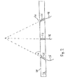
- Fig. 1 shows a schematic perspective view of a pyrometric detection device according to an embodiment of the present invention.
- the pyrometric detection device comprises a pyrometric detecting unit 10 configured to receive thermal radiation.
- the thermal radiation may be electromagnetic radiation in an optical and/or the infrared wavelength range having an intensity maximum at a specific wavelength depending on the temperature at the emission spot (according to the principles of black body radiation).
- the pyrometric detecting unit 10 is further configured to detect the thermal radiation, to generate an electrical signal depending on the thermal radiation, and to output a value indicating a temperature at an emission spot of the thermal radiation.
- the pyrometric detecting unit 10 may comprise a first optical sensor and a second optical sensor (not shown in Fig. 1 ). Each one of the first and second optical sensors is configured to output an electrical signal depending on an intensity of detected thermal radiation in a specific wavelength range. Optical filters and/or wavelength-dependent beam splitters may be used in order to direct the incoming thermal radiation of the desired wavelength range to the respective detector. A value indicating the temperature at the emission spot may be calculated by considering a ratio between the electrical signal of the first optical detector and the electrical signal of the second optical detector.
- the pyrometric detection device further comprises a calibration device 12.
- the calibration device 12 comprises a substrate 14.
- the substrate is plate-shaped.
- the substrate may be formed of metal, e.g. of aluminum (in particular, black anodized aluminum in order to absorb light).
- the calibration device 12 further comprises a plurality of light guides 16.
- the light guides 16 may be optical fibers (glass fibers) or any other kind of light guides 16 configured to direct light of a certain wavelength from a first end thereof to a second end thereof, e.g., by means of total internal reflection.
- Each one of the plurality of light guides 16 has a first end 18 and a second end 20.
- the first ends 18 of the plurality of light guides 16 may be arranged in the form of a bundle. The bundle may be held together by a bundle sleeve 22.
- a light source 24 is provided for emitting light of a wavelength range (e.g., visible and/or infrared), which comprises components detectable by the pyrometric detecting unit 10.
- the light emitted by the light source 24 may be used for calibrating the pyrometric detection device.
- Further optical elements like mirrors, beam splitters, and/or lenses (not shown) may be provided for directing the light emitted by the light source 24 to the first ends 18 of the plurality of light guides 16.
- Light emitted by the light source 24 is coupled into the light guides 16 via their first ends 18.
- the light source 24 and the first ends 18 are arranged such, that the intensity of light coupled into each one of the light guides 16 is substantially the same.
- a gas discharge lamp or a laser with a (widened) top-hat beam profile may be used.
- a plurality of light sources may be provided for emitting light of a constant intensity to the first ends 18 of the light guides 16, such that the intensity of the light coupled into each one of the light guides 16 is substantially the same.
- Each one of the second ends 20 of the plurality of light guides 16 is fixed to the substrate 14, such that a position of the respective second end 20 and an orientation of the respective second end 20 with respect to the substrate 14 do not change with time.
- parts of the light guides close to their second ends 20 may be glued or otherwise mechanically attached to the substrate 14.
- the plurality of light guides 16 may be directed through through-holes 26 provided in the substrate.
- a corresponding through-hole 26 may be provided, through which the respective light guide 16 is directed.
- the light guides 16 may be fixed to the substrate 14 by fastening means provided in the through-holes 26 (e.g., a glue or a resin).
- the second ends 20 of the plurality of light guides 16 are provided such that they are provided substantially in a common plane.
- this plane corresponds to a surface plane 28 of the substrate 14.
- this plane may correspond, e.g., to a plane parallel to the surface plane 28 above or inside the substrate 14.
- side walls of the through holes 26 may be used for blocking light emitted at undesired directions not corresponding to a main light emission direction of the respective light guide 16.
- the pyrometric detecting unit 10 is configured to receive thermal radiation emitted at different points in the detection plane.
- a light directing unit 30 may be provided for directing light emitted at predetermined points of the detection plane to the pyrometric detecting unit 10.
- the light directing unit 30 may comprise, e.g., a rotatable mirror having two rotation axes or a plurality of rotatable mirrors.
- the light directing unit 30 may be electrically controllable such that light (thermal radiation) emitted at a specific predetermined point of the detection plane is directed to the pyrometric detecting unit 10.
- each one of the plurality of light guides 16 may have substantially the same length. Further, each one of the plurality of light guides 16 may have the same optical properties, such that a ratio between an intensity coupled into the light guide 16 and an intensity emitted from the light guide 16 is the same for each one of the light guides 16. If the same light intensity is coupled into the plurality of light guides 16 via their first ends 18, the intensity of light emitted from each one of the second ends 20 may also be the same for each one of the plurality of light guides 16.
- Each one of the plurality of light guides 16 has a main light emission direction.
- the main light emission direction corresponds to a direction in which a maximum of light intensity is emitted via the second end 20 of the respective light guide 16.
- the main light emission direction may correspond to a direction in which the light guide 16 is oriented at its second end 20.
- the main light emission direction may correspond to an extension direction of the light guide 16 at its second end 20.
- the main light emission direction of a light guide 16 may correspond to a direction in which the second end 20 of the respective light guide 16 faces.
- each of the plurality of light guides 16 may not only emit light into its main light emission direction but also into a full half space.
- the second ends 20 of the plurality of light guides 16 are arranged in the detection plane such that they emit light in the detection direction of the pyrometric detecting unit 10.
- the plurality of light guides 16 may be arranged, such that the main light emission direction (indicated by a dashed line) corresponds to the light detection direction of the pyrometric detecting unit 10.
- the main light emission direction of each one of the plurality of light guides 16 may be directed to the light directing unit 30.
- the light directing unit 30 (comprising, e.g., a rotatable mirror) directs the thermal radiation (and/or the light) emitted at predetermined points of the detection plane to the pyrometric detecting unit 10.
- the light directing unit 30 directs the thermal radiation (and/or the light) emitted at predetermined points of the detection plane to the pyrometric detecting unit 10.
- the pyrometric detecting unit 10 Depending on an orientation state of the light directing unit 30, light emitted from a predetermined one of the second ends 20 may be directed to the pyrometric detecting unit 10.
- the second ends 20 of the plurality of light guides 16 may be arranged in a matrix. Exemplarily, a 3 times 3 matrix is shown in Fig. 1 . However, any n times m matrix may be used having n rows and m columns. As shown in Fig. 1 , the total number of light guides 16 is 9 (3 times 3). The total number of light guides may be increased (e.g., to 16, 25, 36, 49, or any other arbitrary number) in order to increase a calibration accuracy of the pyrometric detection device.
- the arrangement of the second ends 20 with respect to the substrate 14 is not limited to a matrix and any other two-dimensional arrangement may be used as long as the second ends 20 are provided in a common plane.
- the shape of the substrate is not limited to a plate-shaped substrate. Any other shape may be used (e.g., a grid or a box).
- the calibration device 12 in a calibration state of the pyrometric detection device, the calibration device 12 is positioned in the manner described above.
- the pyrometric detection device might be operated in different states, in which the calibration device 12 is removed, e.g., as described later with respect to Fig. 4 .
- Fig. 2 shows a schematic cross section of an embodiment of a pyrometric detection device, the cross section being taken along the line A-A of Fig. 1 .
- Each one of the plurality of light guides 16 is directed through a corresponding through-hole 26, such that each one of the second ends 20 is substantially arranged in the surface plane 28 of the substrate 14.
- the second ends 20 may be arranged in a plane above or below the surface plane 28.
- At least one of the through-holes 26 is provided in an oblique angle ⁇ with respect to the plane in which the second ends 20 are arranged, which corresponds to the detection plane of the pyrometric detecting unit 10.
- a main light emission direction may be determined (as indicated by the dashed lines in Fig. 2 ).
- the light guides 16 are provided such that they emit light via their respective second ends 20 in the detection direction. More specifically, the plurality of light guides 16 may be arranged, such that a main light emission direction of each one of the light guides 16 corresponds to a light detection direction of the pyrometric detecting unit 10.
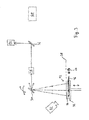
- Fig. 3 shows a schematic side view of an apparatus for producing three-dimensional work pieces in the calibration state.
- Features of the apparatus having the same reference signs as used in the description of Fig. 1 or Fig. 2 above correspond to the same or similar features. A description of these features therefore may be omitted.
- Fig. 3 shows a schematic side view of a part of an apparatus for producing three-dimensional work pieces.
- the apparatus may be, e.g., an apparatus for powder bed fusion.
- the apparatus comprises a carrier 32 having a surface plane.
- a three-dimensional work piece 44 is built on the carrier 32.
- a calibration device 12 is positioned on the carrier 32.
- the calibration device 12 may be, e.g., the calibration device 12 described above with reference to Figs. 1 and 2 .
- the first ends 18 of the plurality of light guides 16 are illuminated with light from the light source 24, such that light having the same intensity is emitted from each one of the second ends 20 towards the light directing unit 30.
- the second ends 20 of the plurality of light guides 16 are arranged in the detection plane 38 of the pyrometric detecting unit 10.
- the detection plane 38 may be defined by a surface plane of the substrate 14.
- the detection plane is a plane parallel to a surface plane of the carrier 32.
- An orientation of the light directing unit 30 is electrically controlled, such that at one time substantially only light emitted from one of the plurality of light guides 16 is directed in the direction of the pyrometric detecting device 10.
- An optical unit 34 may be provided between the light directing unit 30 and the pyrometric detecting unit 10. Further, a second optical unit (not shown) may be provided between the light directing unit 30 and the detection plane 38. The optical unit 34 may also be omitted and only the second optical unit may be provided.
- the optical unit(s) may be configured to focus the thermal radiation (the light) emitted at a certain point (or a certain small area) in the detection plane 38 to the pyrometric detecting unit 10. Thus, a focal spot in the detection plane 38 may be adjusted. The focal spot may be adjusted, e.g., such that substantially only the light emitted from one of the plurality of light guides 16 is directed to the pyrometric detecting unit 10.
- a beam splitter 36 (e.g., a semi-transparent mirror) is provided for directing the light emitted from the light guides 16 to the pyrometric detecting unit 10.
- the semi-beam splitter 36 may be wavelength-dependent, such that preferably thermal radiation (light in a wavelength region of thermal radiation) is reflected towards the pyrometric detecting unit 10.
- the pyrometric detecting unit 10 detects light emitted from one of the plurality of second ends 20 arranged in the detection plane 38.
- the orientation of the light directing unit 30 is changed, such that at a predetermined time, the light emitted from one predetermined light guide 16 arranged at a predetermined position in the detection plane 38 is detected by the pyrometric detecting unit 10. For example, at a time t 1 the light emitted by a light guide 16, the second end 20 of which is positioned at a location X 1 , Y 1 , may be detected.
- the light emitted by a light guide 16 the second end 20 of which is positioned at a location X 2 , Y 2 different from the location X 1 , Y 1 , may be detected.
- a detection spot of the pyrometric detecting unit 10 is scanned over the detection plane 38. For each of the positions X n , Y m , at least one corresponding intensity value detected by the pyrometric detecting unit 10 is measured.
- the measured values may differ even though a light intensity emitted from each one of the plurality of light guides 16 is substantially the same.
- the pyrometric detection device may be calibrated and angle and/or location dependencies may be compensated.
- an intensity value corresponding to the actual emitted intensity at a location X n , Y m in the detection plane 38 may be measured by the pyrometric detecting unit 10.
- the apparatus further comprises a powder application device 42 for applying a raw material powder onto the carrier 32.
- the apparatus further comprises an irradiation device 40 for selectively irradiating electromagnetic or particle radiation onto the raw material powder applied onto the surface of the carrier 32.
- the irradiation device 40 is a laser 40 emitting light of a wavelength and an intensity adapted to melt the raw material powder at a predetermined melting spot. In the calibration state shown in Fig. 3 , the laser 40 may be turned off or blocked, such that no laser radiation is directed towards the carrier 32.
- the substrate 14, the plurality of light guides 16, and the light source 24 may be arranged in a hermetically sealed chamber (a construction chamber) of the apparatus. Further, a cover may be provided below the substrate 14 in order to cover the light source 24 and the first ends 18 of the plurality of light guides 16, such that no undesired light is emitted into the chamber.
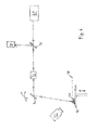
- Fig. 4 shows a schematic side view of the apparatus of Fig. 3 in the operation state.
- a three-dimensional work piece 44 is built on the carrier 32.
- the calibration device 12 is removed from the carrier 32 in the operation state.
- a first layer of raw material powder is applied by the powder application device 42 onto the carrier 32.
- the detection layer of the pyrometric detecting unit 10 substantially corresponds to the surface plane of the carrier 32.
- the laser 40 selectively irradiates laser radiation to an irradiation spot in an irradiation plane. Therefore, a laser beam is emitted by the laser 40 and passes through the beam splitter 36. The laser beam is focused by the optical unit 34 and directed to a predetermined irradiation spot in the irradiation plane by the light directing unit 30.
- the pyrometric detecting unit 10 detects thermal radiation emitted from the irradiating spot.
- the irradiation plane corresponds to the detection plane 38 defined on the carrier 32.
- the optical unit 34 (or the optical unit 34 in combination with another optical unit) may be adapted to change a spot diameter of the laser irradiation. Further, the spot diameter of the laser irradiation may be controllable independently from the detection diameter of the pyrometric detecting unit 10. Therefore, respective optical units may be provided.
- the carrier 32 moves downwards (indicated by an arrow in Fig. 4 ) and a second layer of powder is applied by the powder application device 42. Then, a second layer of the three-dimensional work piece 44 is written by the laser 40.
- the temperature at the irradiation spot (melting spot) is monitored by the pyrometric detecting unit 10. Due to the calibration method described with reference to Fig. 3 , the pyrometric detecting unit 10 may output a reliably temperature value for each position of the irradiation spot on the detection plane 38. Based on the temperature value, an intensity and/or a spot size of the laser beam may be adjusted.
Abstract
Description
- The present invention relates to a pyrometric detection device and a method for calibrating the same. The present invention further relates to an apparatus for producing three-dimensional work pieces.
- Powder bed fusion is an additive layering process by which pulverulent, in particular metallic and/or ceramic raw materials can be processed to three-dimensional work pieces of complex shapes. To that end, a raw material powder layer is applied onto a carrier and subjected to a laser radiation in a site selective manner in dependence on the desired geometry of the work piece that is to be produced. The laser radiation penetrating into the powder layer causes heating and consequently melting or sintering of the raw material powder particles. Further raw material powder layers are then applied successively to the layer on the carrier that has already been subjected to laser treatment, until the work piece has the desired shape and size. Powder bed fusion can be used in particular for the production of prototypes, tools, replacement parts or medical prostheses, such as, for example, dental or orthopaedic prostheses, on the basis of CAD data. Instead of laser irradiation, other electromagnetic or particle radiation, such as electron irradiation, might be used for melting or sintering of the raw material powder particles.
- In order to obtain a work piece having desired physical properties, the melting or sintering conditions at the irradiation spot may be monitored during production by a monitoring device.
- The invention is directed to the object of providing a pyrometric detection device and a method for calibrating the same, which allow a precise monitoring of a building process for generating a three-dimensional work piece by irradiating layers of raw material powder with electromagnetic or particle radiation. The invention is further directed to the object of providing an apparatus for producing three-dimensional work pieces.
- The above object is achieved by a pyrometric detection device as defined in
claim 1, an apparatus for producing three-dimensional work pieces as defined inclaim 10, and a method for calibrating a pyrometric detection device as defined inclaim 14. According to a first aspect, a pyrometric detection device for use in an apparatus for producing three-dimensional work pieces comprises a pyrometric detecting unit configured to receive thermal radiation emitted at different points of a detection plane in a detection direction and a calibration device comprising a substrate and a plurality of light guides each having a first end for coupling light into the light guide and a second end for emitting light from the light guide, the second end being fixed to the substrate. The substrate is adapted to be removably arranged relative to the pyrometric detecting unit in such a manner that the second ends of the plurality of light guides are arranged in the detection plane and emit light in the detection direction, in a calibration state of the pyrometric detection device. - The pyrometric detecting unit may comprise an optical detector sensitive for electromagnetic radiation in a wavelength region corresponding to thermal radiation emitted by a laser melting or sintering spot. In particular, the pyrometric detecting unit may comprise at least two optical detectors for detecting thermal radiation at two different wavelength ranges, wherein optical filters (e.g., high-pass, low-pass or band-pass filters) or wavelength-dependent beam splitters may be used for directing an incoming light beam of thermal radiation in a desired wavelength range to the respective detectors. The thermal radiation may be in the infrared wavelength range and the optical detectors may be sensitive for thermal radiation in the infrared radiation range. The optical detector or the optical detectors of the pyrometric detecting unit may output an electrical signal depending on an irradiation intensity of thermal radiation in a certain wavelength range at the respective detector. An evaluation unit may be provided for calculating a temperature value based on the electrical signal(s) (e.g., based on a ratio of two electrical signals from two detectors detecting thermal radiation at two different wavelength ranges).
- The plurality of light guides of the calibration device may be light guides for directing light (e.g., in the visible or infrared wavelength range) from a first end to a second end thereof by means of total internal reflection. The second ends of the plurality of light guides may be fixed to the substrate, such that an orientation of the second ends with respect to the substrate does not change with time.
- The substrate is adapted to be removably arranged with respect to the pyrometric detecting unit, for example by manually arranging the substrate at a desired location or by using a motor or a robot arm for moving the substrate to a desired location. In the calibration state, the second ends of the plurality of light guides are arranged in the detection plane. The second ends may be light-emitting ends of the plurality of light guides and may be arranged substantially in a plane with respect to the substrate. In the calibration state, this plane corresponds to the detection plane of the pyrometric detecting unit. The light guides are adapted to emit light in the detection direction of the pyrometric detecting unit, such that the light emitted from the plurality of light guides may be detected by the pyrometric detecting unit in the calibration state. The calibration state of the pyrometric detection device may be a calibration state, in which the pyrometric detecting unit is calibrated in order to compensate for dependencies of the pyrometric detecting unit with regard to radiation emitted at different points (i.e., different locations) in the detection plane.
- The substrate may be plate-shaped and the second ends of the plurality of light guides may be arranged in a plane corresponding to an upper side of the plate-shaped substrate. The substrate may be, e.g., a metal plate. In particular, the substrate may be a black anodized aluminium plate.
- Each of the light guides may be directed through a through-hole in the substrate. For example, each one of the plurality of light guides may be directed through an individual through-hole. The plurality of light guides may be fixed to the substrate by means of the through-hole and/or by using fastening means (e.g., a glue or a resin). At least one of the through-holes may be provided in an oblique angle with respect to a surface of the substrate, such that a main light emission direction of the light guide directed through that through-hole is an oblique direction with respect to the surface of the substrate.
- The second ends of the plurality of light guides may be fixed to the substrate such that a main light emission direction of each light guide corresponds to the detection direction of the pyrometric detecting unit, in the calibration state. The main light emission direction may correspond to a direction, in which the highest intensity of light is emitted from the corresponding light guide. In other words, in the calibration state, the second ends of each of the plurality of light guides may be oriented, such that a maximum of emitted light intensity from each one of the light guides is oriented in the detection direction of the pyrometric detecting unit.
- The second ends of the plurality of light guides may be fixed to the substrate such that they are oriented in the detection direction of the pyrometric detecting unit, in the calibration state. In other words, the main light emission direction may correspond to a direction in which the light guide is oriented, i.e., a direction in which the second end of the corresponding light guide is oriented.
- The second ends of the plurality of light guides may be arranged on the substrate in the form of a matrix. For example, a plurality of through-holes, through which the light guides are directed, may be arranged in the form a matrix. The matrix may be, e.g., an n times m matrix having n rows and m columns, wherein the rows are arranged parallel to each other and the columns are arranged parallel to each other. The rows and the columns may intersect each other at an angle of 90 degrees. At each intersection, a second end of one of the plurality of light guides may be arranged. The matrix may be an n times n matrix having the same amount of rows and columns. The distance between each pair of adjacent columns may be the same and the distance between each pair of adjacent rows may be the same. Further, the distance between adjacent columns may be the same as the distance between adjacent rows.
- The pyrometric detection device may further comprise a light source adapted to couple light into each of the plurality of light guides via their first ends, wherein the intensity of the light coupled into each of the plurality of light guides is substantially the same. The light source may direct a light beam to each of the plurality of first ends, such that the same amount of light (the same intensity) is coupled into each one of the light guides. For example, a gas discharge lamp or a laser having a top-hat beam profile may be used as a light source. In case a laser is used, the laser may emit light having a wavelength which differs from the wavelength of the thermal radiation detected by the pyrometric detection unit.
- The light guides may be glass fibers and the first ends of the plurality of light guides may be arranged next to each other in the form of a bundle. The bundle may be held together by means of a bundle sleeve. The bundle may be arranged such that each of the plurality of first ends is oriented in the same direction. A light source may be provided for illuminating the bundle, such that substantially the same intensity of light is coupled into each one of the plurality of light guides.
- Each of the light guides may have the same length. Further, each of the light guides may have the same optical properties. The intensity of light coupled out of the second ends of each of the plurality of light guides may be the same.
- According to a second aspect, an apparatus for producing three-dimensional work pieces comprises a carrier, a powder application device for applying a raw material powder onto the carrier, and an irradiation device for selectively irradiating electromagnetic or particle radiation onto the raw material powder applied onto the surface of the carrier. The apparatus further comprises the pyrometric detection device defined herein, wherein the detection plane of the pyrometric detection device corresponds to an irradiation plane defined on the carrier.
- The apparatus may be an apparatus for powder bed fusion. The pyrometric detecting unit of the pyrometric detection device may be mounted on the apparatus and the substrate of the calibration device may be adapted to be removably arranged with respect to the apparatus. In the calibration state, the second ends of the plurality of light guides may be arranged in the irradiation plane of the apparatus. The irradiation plane may be defined on the carrier, such that the irradiation plane is a plane parallel to a surface plane of the carrier. During operation of the apparatus, when writing a first layer of a three-dimensional work piece, the irradiation plane may substantially correspond to a surface plane of the carrier.
- In the calibration state, the substrate, the plurality of light guides, and the light source may be arranged inside a process chamber of the apparatus. The process chamber may be chamber which is adapted to be hermetically sealed. The processe chamber may be evacuated before an operation state of the apparatus is initiated. Further, the chamber may be filled with a predefined gas, in particular an inert gas, during the operation state.
- The irradiation device may comprise a laser source configured to emit a laser beam and an optical unit configured to direct the laser beam to predetermined points of the irradiation plane. The laser source may be an infrared laser source. The laser source may be adapted to emit a laser beam for melting or sintering a raw material powder. The optical unit may comprise a rotatable mirror. The rotatable mirror may be rotatable about at least two rotation axes, such that the laser beam may be directed to predetermined points in the two dimensions of the irradiation plane. Further, the optical unit may comprise other optical elements, e.g., at least one lens. A lens or a plurality of lenses may be provided for focusing the laser beam onto the irradiation plane. Further, movable lenses may be provided for narrowing or broadening an irradiation spot in the irradiation plane.
- The optical unit may be configured to direct the thermal radiation emitted at the different points of the detection plane to the pyrometric detecting unit and the detection direction at each point of the detection plane may be opposite to an incidence direction of the laser beam. The thermal radiation at a point of the detection plane may be caused by laser melting of raw material powder at that point of the detection plane, wherein the detection plane corresponds to an irradiation plane of the apparatus. Further, in the calibration state, the optical unit may be configured to direct the light emitted from the second ends of the plurality of light guides to the pyrometric detecting unit. The optical unit may be configured to direct the laser light coming from the laser source to the irradiation plane (corresponding to the detection plane). An optical path of the laser beam and an optical path of thermal radiation detected by the pyrometric detecting unit may correspond to each other, at least in part.
- According to a third aspect, a method for calibrating a pyrometric detection device for use in an apparatus for producing three-dimensional work pieces comprises removably arranging a calibration device relative to a pyrometric detecting unit configured to receive thermal radiation emitted at different points of a detection plane in a detection direction. The calibration device comprises a substrate and a plurality of light guides each having a first end for coupling light into the light guide and a second end for emitting light from the light guide, the second end being fixed to the substrate, wherein the second ends of the plurality of light guides are arranged in the detection plane. The method further comprises coupling light into each of the plurality of light guides via the first ends, individually measuring the intensity of light emitted from each of the second ends of the plurality of light guides in the detection direction by means of the pyrometric detecting unit, and calibrating the pyrometric detecting unit based on the results of the intensity measurements.
- The results of the intensity measurements may be saved in a memory of the apparatus. The step of calibrating may be carried out by a computer. Further steps of method may also be carried out automatically by a controller of the apparatus.
- The intensity of the light coupled into each of the plurality of light guides may be substantially the same. For example, a light source may be used for irradiating each one of the first ends of the light guides with a constant light intensity.
- Preferred embodiments of the invention now are described in greater detail with reference to the appended schematic drawings, wherein
- Fig. 1
- shows a schematic perspective view of a pyrometric detection device for use in an apparatus for producing three-dimensional work pieces;
- Fig. 2
- shows a schematic cross section of the pyrometric detection device along the line A-A of
Fig. 1 ; - Fig. 3
- shows a schematic side view of an apparatus for producing three-dimensional work pieces in the calibration state; and
- Fig. 4
- shows a schematic side view of an apparatus for producing three-dimensional work pieces in the operation state.
-
Fig. 1 shows a schematic perspective view of a pyrometric detection device according to an embodiment of the present invention. The pyrometric detection device comprises apyrometric detecting unit 10 configured to receive thermal radiation. The thermal radiation may be electromagnetic radiation in an optical and/or the infrared wavelength range having an intensity maximum at a specific wavelength depending on the temperature at the emission spot (according to the principles of black body radiation). Thepyrometric detecting unit 10 is further configured to detect the thermal radiation, to generate an electrical signal depending on the thermal radiation, and to output a value indicating a temperature at an emission spot of the thermal radiation. - For example, the
pyrometric detecting unit 10 may comprise a first optical sensor and a second optical sensor (not shown inFig. 1 ). Each one of the first and second optical sensors is configured to output an electrical signal depending on an intensity of detected thermal radiation in a specific wavelength range. Optical filters and/or wavelength-dependent beam splitters may be used in order to direct the incoming thermal radiation of the desired wavelength range to the respective detector. A value indicating the temperature at the emission spot may be calculated by considering a ratio between the electrical signal of the first optical detector and the electrical signal of the second optical detector. - The pyrometric detection device further comprises a
calibration device 12. Thecalibration device 12 comprises asubstrate 14. In the embodiment ofFig. 1 , the substrate is plate-shaped. The substrate may be formed of metal, e.g. of aluminum (in particular, black anodized aluminum in order to absorb light). Thecalibration device 12 further comprises a plurality of light guides 16. The light guides 16 may be optical fibers (glass fibers) or any other kind of light guides 16 configured to direct light of a certain wavelength from a first end thereof to a second end thereof, e.g., by means of total internal reflection. Each one of the plurality of light guides 16 has afirst end 18 and asecond end 20. As shown inFig. 1 , the first ends 18 of the plurality of light guides 16 may be arranged in the form of a bundle. The bundle may be held together by abundle sleeve 22. - A
light source 24 is provided for emitting light of a wavelength range (e.g., visible and/or infrared), which comprises components detectable by thepyrometric detecting unit 10. Thus, the light emitted by thelight source 24 may be used for calibrating the pyrometric detection device. Further optical elements like mirrors, beam splitters, and/or lenses (not shown) may be provided for directing the light emitted by thelight source 24 to the first ends 18 of the plurality of light guides 16. Light emitted by thelight source 24 is coupled into the light guides 16 via their first ends 18. Thelight source 24 and the first ends 18 are arranged such, that the intensity of light coupled into each one of the light guides 16 is substantially the same. Aslight source 24, e.g., a gas discharge lamp or a laser with a (widened) top-hat beam profile may be used. - Alternatively, a plurality of light sources may be provided for emitting light of a constant intensity to the first ends 18 of the light guides 16, such that the intensity of the light coupled into each one of the light guides 16 is substantially the same.
- Each one of the second ends 20 of the plurality of light guides 16 is fixed to the
substrate 14, such that a position of the respectivesecond end 20 and an orientation of the respectivesecond end 20 with respect to thesubstrate 14 do not change with time. For example, parts of the light guides close to their second ends 20 may be glued or otherwise mechanically attached to thesubstrate 14. As shown inFig. 1 , the plurality of light guides 16 may be directed through through-holes 26 provided in the substrate. For each one of the second ends 20, a corresponding through-hole 26 may be provided, through which the respectivelight guide 16 is directed. The light guides 16 may be fixed to thesubstrate 14 by fastening means provided in the through-holes 26 (e.g., a glue or a resin). - The second ends 20 of the plurality of light guides 16 are provided such that they are provided substantially in a common plane. In the embodiment shown in
Fig. 1 , this plane corresponds to asurface plane 28 of thesubstrate 14. However, in other embodiments, this plane may correspond, e.g., to a plane parallel to thesurface plane 28 above or inside thesubstrate 14. For example, if the second ends 20 are arranged in a plane parallel to thesurface plane 28 and inside thesubstrate 14, side walls of the throughholes 26 may be used for blocking light emitted at undesired directions not corresponding to a main light emission direction of the respectivelight guide 16. - The plane, in which the plurality of second ends 20 are arranged, corresponds to a detection plane of the
pyrometric detecting unit 10. Thepyrometric detecting unit 10 is configured to receive thermal radiation emitted at different points in the detection plane. Alight directing unit 30 may be provided for directing light emitted at predetermined points of the detection plane to thepyrometric detecting unit 10. Thelight directing unit 30 may comprise, e.g., a rotatable mirror having two rotation axes or a plurality of rotatable mirrors. Thelight directing unit 30 may be electrically controllable such that light (thermal radiation) emitted at a specific predetermined point of the detection plane is directed to thepyrometric detecting unit 10. - When the light is coupled from the
light source 24 into the plurality of light guides 16, light is emitted from the second ends 20 of the plurality of light guides 16. Each one of the plurality of light guides 16 may have substantially the same length. Further, each one of the plurality of light guides 16 may have the same optical properties, such that a ratio between an intensity coupled into thelight guide 16 and an intensity emitted from thelight guide 16 is the same for each one of the light guides 16. If the same light intensity is coupled into the plurality of light guides 16 via their first ends 18, the intensity of light emitted from each one of the second ends 20 may also be the same for each one of the plurality of light guides 16. - Each one of the plurality of light guides 16 has a main light emission direction. The main light emission direction corresponds to a direction in which a maximum of light intensity is emitted via the
second end 20 of the respectivelight guide 16. For example, the main light emission direction may correspond to a direction in which thelight guide 16 is oriented at itssecond end 20. In other words, the main light emission direction may correspond to an extension direction of thelight guide 16 at itssecond end 20. The main light emission direction of alight guide 16 may correspond to a direction in which thesecond end 20 of the respectivelight guide 16 faces. - However, each of the plurality of light guides 16 may not only emit light into its main light emission direction but also into a full half space. The second ends 20 of the plurality of light guides 16 are arranged in the detection plane such that they emit light in the detection direction of the
pyrometric detecting unit 10. As shown in the embodiment ofFig. 1 , the plurality of light guides 16 may be arranged, such that the main light emission direction (indicated by a dashed line) corresponds to the light detection direction of thepyrometric detecting unit 10. For example, the main light emission direction of each one of the plurality of light guides 16 may be directed to thelight directing unit 30. As explained above, the light directing unit 30 (comprising, e.g., a rotatable mirror) directs the thermal radiation (and/or the light) emitted at predetermined points of the detection plane to thepyrometric detecting unit 10. Depending on an orientation state of thelight directing unit 30, light emitted from a predetermined one of the second ends 20 may be directed to thepyrometric detecting unit 10. - As shown in
Fig. 1 , the second ends 20 of the plurality of light guides 16 may be arranged in a matrix. Exemplarily, a 3 times 3 matrix is shown inFig. 1 . However, any n times m matrix may be used having n rows and m columns. As shown inFig. 1 , the total number of light guides 16 is 9 (3 times 3). The total number of light guides may be increased (e.g., to 16, 25, 36, 49, or any other arbitrary number) in order to increase a calibration accuracy of the pyrometric detection device. The arrangement of the second ends 20 with respect to thesubstrate 14 is not limited to a matrix and any other two-dimensional arrangement may be used as long as the second ends 20 are provided in a common plane. - Further, the shape of the substrate is not limited to a plate-shaped substrate. Any other shape may be used (e.g., a grid or a box).
- As shown in
Fig. 1 , in a calibration state of the pyrometric detection device, thecalibration device 12 is positioned in the manner described above. However, the pyrometric detection device might be operated in different states, in which thecalibration device 12 is removed, e.g., as described later with respect toFig. 4 . -
Fig. 2 shows a schematic cross section of an embodiment of a pyrometric detection device, the cross section being taken along the line A-A ofFig. 1 . Each one of the plurality of light guides 16 is directed through a corresponding through-hole 26, such that each one of the second ends 20 is substantially arranged in thesurface plane 28 of thesubstrate 14. As described above, alternatively, the second ends 20 may be arranged in a plane above or below thesurface plane 28. At least one of the through-holes 26 is provided in an oblique angle α with respect to the plane in which the second ends 20 are arranged, which corresponds to the detection plane of thepyrometric detecting unit 10. By providing oblique through-holes 26, an orientation of thelight guide 16 directed through the throughhole 26 may be determined. Thus, a main light emission direction may be determined (as indicated by the dashed lines inFig. 2 ). As shown inFig. 2 , the light guides 16 are provided such that they emit light via their respective second ends 20 in the detection direction. More specifically, the plurality of light guides 16 may be arranged, such that a main light emission direction of each one of the light guides 16 corresponds to a light detection direction of thepyrometric detecting unit 10. -
Fig. 3 shows a schematic side view of an apparatus for producing three-dimensional work pieces in the calibration state. Features of the apparatus having the same reference signs as used in the description ofFig. 1 orFig. 2 above correspond to the same or similar features. A description of these features therefore may be omitted. -
Fig. 3 shows a schematic side view of a part of an apparatus for producing three-dimensional work pieces. The apparatus may be, e.g., an apparatus for powder bed fusion. The apparatus comprises acarrier 32 having a surface plane. In an operation state of the apparatus (see description ofFig. 4 below), a three-dimensional work piece 44 is built on thecarrier 32. However, in the calibration state shown inFig. 3 , acalibration device 12 is positioned on thecarrier 32. Thecalibration device 12 may be, e.g., thecalibration device 12 described above with reference toFigs. 1 and2 . - In the calibration state, the first ends 18 of the plurality of light guides 16 are illuminated with light from the
light source 24, such that light having the same intensity is emitted from each one of the second ends 20 towards thelight directing unit 30. The second ends 20 of the plurality of light guides 16 are arranged in thedetection plane 38 of thepyrometric detecting unit 10. As shown inFig. 3 , thedetection plane 38 may be defined by a surface plane of thesubstrate 14. The detection plane is a plane parallel to a surface plane of thecarrier 32. - An orientation of the
light directing unit 30 is electrically controlled, such that at one time substantially only light emitted from one of the plurality of light guides 16 is directed in the direction of the pyrometric detectingdevice 10. Anoptical unit 34 may be provided between thelight directing unit 30 and thepyrometric detecting unit 10. Further, a second optical unit (not shown) may be provided between thelight directing unit 30 and thedetection plane 38. Theoptical unit 34 may also be omitted and only the second optical unit may be provided. The optical unit(s) may be configured to focus the thermal radiation (the light) emitted at a certain point (or a certain small area) in thedetection plane 38 to thepyrometric detecting unit 10. Thus, a focal spot in thedetection plane 38 may be adjusted. The focal spot may be adjusted, e.g., such that substantially only the light emitted from one of the plurality of light guides 16 is directed to thepyrometric detecting unit 10. - Further, a beam splitter 36 (e.g., a semi-transparent mirror) is provided for directing the light emitted from the light guides 16 to the
pyrometric detecting unit 10. Thesemi-beam splitter 36 may be wavelength-dependent, such that preferably thermal radiation (light in a wavelength region of thermal radiation) is reflected towards thepyrometric detecting unit 10. - In the calibration state, the
pyrometric detecting unit 10 detects light emitted from one of the plurality of second ends 20 arranged in thedetection plane 38. During calibration, the orientation of thelight directing unit 30 is changed, such that at a predetermined time, the light emitted from onepredetermined light guide 16 arranged at a predetermined position in thedetection plane 38 is detected by thepyrometric detecting unit 10. For example, at a time t1 the light emitted by alight guide 16, thesecond end 20 of which is positioned at a location X1, Y1, may be detected. For example, at a time t2 the light emitted by alight guide 16, thesecond end 20 of which is positioned at a location X2, Y2 different from the location X1, Y1, may be detected. Thus, a detection spot of thepyrometric detecting unit 10 is scanned over thedetection plane 38. For each of the positions Xn, Ym, at least one corresponding intensity value detected by thepyrometric detecting unit 10 is measured. - Due to angle and/or location dependencies of the
light directing unit 30 and/or thepyrometric detecting unit 10, the measured values may differ even though a light intensity emitted from each one of the plurality of light guides 16 is substantially the same. By comparing the different measured values, the pyrometric detection device may be calibrated and angle and/or location dependencies may be compensated. Thus, an intensity value corresponding to the actual emitted intensity at a location Xn, Ym in thedetection plane 38 may be measured by thepyrometric detecting unit 10. - The apparatus further comprises a
powder application device 42 for applying a raw material powder onto thecarrier 32. The apparatus further comprises anirradiation device 40 for selectively irradiating electromagnetic or particle radiation onto the raw material powder applied onto the surface of thecarrier 32. In the embodiment shown inFig. 3 , theirradiation device 40 is alaser 40 emitting light of a wavelength and an intensity adapted to melt the raw material powder at a predetermined melting spot. In the calibration state shown inFig. 3 , thelaser 40 may be turned off or blocked, such that no laser radiation is directed towards thecarrier 32. - The
substrate 14, the plurality of light guides 16, and thelight source 24 may be arranged in a hermetically sealed chamber (a construction chamber) of the apparatus. Further, a cover may be provided below thesubstrate 14 in order to cover thelight source 24 and the first ends 18 of the plurality of light guides 16, such that no undesired light is emitted into the chamber. -
Fig. 4 shows a schematic side view of the apparatus ofFig. 3 in the operation state. In the operation state, a three-dimensional work piece 44 is built on thecarrier 32. Hence, thecalibration device 12 is removed from thecarrier 32 in the operation state. In the operation state, a first layer of raw material powder is applied by thepowder application device 42 onto thecarrier 32. At the time of writing the first layer, the detection layer of thepyrometric detecting unit 10 substantially corresponds to the surface plane of thecarrier 32. - At the time of writing the first layer, the
laser 40 selectively irradiates laser radiation to an irradiation spot in an irradiation plane. Therefore, a laser beam is emitted by thelaser 40 and passes through thebeam splitter 36. The laser beam is focused by theoptical unit 34 and directed to a predetermined irradiation spot in the irradiation plane by thelight directing unit 30. - At the same time, the
pyrometric detecting unit 10 detects thermal radiation emitted from the irradiating spot. Thus, the irradiation plane corresponds to thedetection plane 38 defined on thecarrier 32. The optical unit 34 (or theoptical unit 34 in combination with another optical unit) may be adapted to change a spot diameter of the laser irradiation. Further, the spot diameter of the laser irradiation may be controllable independently from the detection diameter of thepyrometric detecting unit 10. Therefore, respective optical units may be provided. - After the first layer of the three-
dimensional work piece 44 is entirely written, thecarrier 32 moves downwards (indicated by an arrow inFig. 4 ) and a second layer of powder is applied by thepowder application device 42. Then, a second layer of the three-dimensional work piece 44 is written by thelaser 40. During the writing process the temperature at the irradiation spot (melting spot) is monitored by thepyrometric detecting unit 10. Due to the calibration method described with reference toFig. 3 , thepyrometric detecting unit 10 may output a reliably temperature value for each position of the irradiation spot on thedetection plane 38. Based on the temperature value, an intensity and/or a spot size of the laser beam may be adjusted.
Claims (15)
- A pyrometric detection device for use in an apparatus for producing three-dimensional work pieces, the pyrometric detection device comprising:a pyrometric detecting unit (10) configured to receive thermal radiation emitted at different points of a detection plane (38) in a detection direction, anda calibration device (12) comprising a substrate (14) and a plurality of light guides (16) each having a first end (18) for coupling light into the light guide (16) and a second end (20) for emitting light from the light guide (16), the second end (20) being fixed to the substrate (14), whereinthe substrate (14) is adapted to be removably arranged relative to the pyrometric detecting unit (10) in such a manner that the second ends (20) of the plurality of light guides (16) are arranged in the detection plane (38) and emit light in the detection direction, in a calibration state of the pyrometric detection device.
- The pyrometric detection device according to claim 1, wherein
the substrate (14) is plate-shaped; and
the second ends (20) of the plurality of light guides (16) are arranged in a plane corresponding to an upper surface (28) of the plate-shaped substrate (14). - The pyrometric detection device according to claim 1 or 2, wherein
each of the light guides (16) is directed through a through-hole (20) in the substrate (14). - The pyrometric detection device according to any one of claims 1 to 3, wherein
the second ends (20) of the plurality of light guides (16) are fixed to the substrate (14) such that a main light emission direction of each light guide (16) corresponds to the detection direction of the pyrometric detecting unit (10), in the calibration state. - The pyrometric detection device according to claim 4, wherein
the second ends (20) of the plurality of light guides (16) are fixed to the substrate (14) such that they are oriented in the detection direction of the pyrometric detecting unit (10), in the calibration state. - The pyrometric detection device according to any one of claims 1 to 5, wherein
the second ends (20) of the plurality of light guides (16) are arranged on the substrate (14) in the form of a matrix. - The pyrometric detection device according to any one of claims 1 to 6, further comprising
a light source (24) adapted to couple light into each of the plurality of light guides (16) via their first ends (18), wherein
the intensity of the light coupled into each of the plurality of light guides (16) is substantially the same. - The pyrometric detection device according to any one of claims 1 to 7, wherein
the light guides (16) are glass fibers; and
the first ends (18) of the plurality of light guides (16) are arranged next to each other in the form of a bundle. - The pyrometric detection device according to any one of claims 1 to 8, wherein each of the light guides (16) has the same length.
- An apparatus for producing three-dimensional work pieces, the apparatus comprising:a carrier (32);a powder application device (42) for applying a raw material powder onto the carrier (32);an irradiation device (40) for selectively irradiating electromagnetic or particle radiation onto the raw material powder applied onto the surface of the carrier (32);the pyrometric detection device according to any one of claims 1 to 9, whereinthe detection plane (38) of the pyrometric detection device corresponds to an irradiation plane defined on the carrier (32).
- The apparatus according to claim 10 in combination with claim 7, wherein
in the calibration state,
the substrate (14), the plurality of light guides (16), and the light source (24) are arranged inside a hermetically sealed chamber of the apparatus. - The apparatus according to claim 10 or 11, wherein
the irradiation device (40) comprises a laser source configured to emit a laser beam and a light directing unit (30) configured to direct the laser beam to predetermined points of the irradiation plane (38). - The apparatus according to claim 12, wherein
the light directing unit (30) is configured to direct the thermal radiation emitted at the different points of the detection plane (38) to the pyrometric detecting unit (10); and
the detection direction at each point of the detection plane (38) is opposite to an incidence direction of the laser beam. - A method for calibrating a pyrometric detection device for use in an apparatus for producing three-dimensional work pieces, the method comprising:removably arranging a calibration device (12) relative to a pyrometric detecting unit (10) configured to receive thermal radiation emitted at different points of a detection plane (38) in a detection direction, the calibration device (12) comprising a substrate (14) and a plurality of light guides (16) each having a first end (18) for coupling light into the light guide (16) and a second end (20) for emitting light from the light guide (16), the second end (20) being fixed to the substrate (14), wherein the second ends (20) of the plurality of light guides (16) are arranged in the detection plane (38);coupling light into each of the plurality of light guides (16) via the first ends (18);individually measuring the intensity of light emitted from each of the second ends (20) of the plurality of light guides (16) in the detection direction (38) by means of the pyrometric detecting unit (10); andcalibrating the pyrometric detecting unit (10) based on the results of the intensity measurements.
- The method according to claim 14, wherein
the intensity of the light coupled into each of the plurality of light guides (16) is substantially the same.
Priority Applications (4)
| Application Number | Priority Date | Filing Date | Title |
|---|---|---|---|
| EP14194378.7A EP3023757B1 (en) | 2014-11-21 | 2014-11-21 | Pyrometric detection device, method for calibrating the same, and apparatus for producing three-dimensional work pieces |
| JP2015210383A JP6158893B2 (en) | 2014-11-21 | 2015-10-27 | High temperature measurement device, calibration method for the high temperature measurement device, and three-dimensional workpiece manufacturing apparatus |
| CN201510777582.9A CN105628210B (en) | 2014-11-21 | 2015-11-13 | High-temperature detection device, its calibration method and the equipment for producing 3 D workpiece |
| US14/940,838 US9903762B2 (en) | 2014-11-21 | 2015-11-13 | Pyrometric detection device, method for calibrating the same, and apparatus for producing three-dimensional work pieces |
Applications Claiming Priority (1)
| Application Number | Priority Date | Filing Date | Title |
|---|---|---|---|
| EP14194378.7A EP3023757B1 (en) | 2014-11-21 | 2014-11-21 | Pyrometric detection device, method for calibrating the same, and apparatus for producing three-dimensional work pieces |
Publications (2)
| Publication Number | Publication Date |
|---|---|
| EP3023757A1 true EP3023757A1 (en) | 2016-05-25 |
| EP3023757B1 EP3023757B1 (en) | 2019-04-03 |
Family
ID=51945772
Family Applications (1)
| Application Number | Title | Priority Date | Filing Date |
|---|---|---|---|
| EP14194378.7A Active EP3023757B1 (en) | 2014-11-21 | 2014-11-21 | Pyrometric detection device, method for calibrating the same, and apparatus for producing three-dimensional work pieces |
Country Status (4)
| Country | Link |
|---|---|
| US (1) | US9903762B2 (en) |
| EP (1) | EP3023757B1 (en) |
| JP (1) | JP6158893B2 (en) |
| CN (1) | CN105628210B (en) |
Cited By (5)
| Publication number | Priority date | Publication date | Assignee | Title |
|---|---|---|---|---|
| DE102016223215A1 (en) | 2016-11-23 | 2018-05-24 | Trumpf Laser- Und Systemtechnik Gmbh | Irradiation device and processing machine with it |
| EP3524411A1 (en) * | 2018-02-09 | 2019-08-14 | CL Schutzrechtsverwaltungs GmbH | Method for calibrating at least one apparatus for additively manufacturing three-dimensional objects |
| EP3626437A1 (en) * | 2018-09-21 | 2020-03-25 | Concept Laser GmbH | Method for calibrating an apparatus for additively manufacturing threedimensional objects |
| US20200408613A1 (en) * | 2018-07-12 | 2020-12-31 | Tokyo Electron Limited | Temperature measurement sensor, temperature measurement system, and temperature measurement method |
| US11027494B2 (en) | 2016-05-13 | 2021-06-08 | SLM Solutions Group AG | Device and method for calibrating an irradiation system of an apparatus for producing a three-dimensional work piece |
Families Citing this family (3)
| Publication number | Priority date | Publication date | Assignee | Title |
|---|---|---|---|---|
| CN106142287B (en) * | 2016-07-06 | 2019-01-11 | 嘉兴钛胺新材料科技有限公司 | A kind of 3D printer with automatic alarm prompt facility |
| EP3441214B1 (en) * | 2017-08-09 | 2022-09-28 | CL Schutzrechtsverwaltungs GmbH | Apparatus for additively manufacturing of three-dimensional objects |
| EP3508334A1 (en) * | 2018-01-08 | 2019-07-10 | CL Schutzrechtsverwaltungs GmbH | Apparatus for additively manufacturing of three-dimensional objects |
Citations (2)
| Publication number | Priority date | Publication date | Assignee | Title |
|---|---|---|---|---|
| WO1998053286A1 (en) * | 1997-05-22 | 1998-11-26 | Applied Materials, Inc. | Pyrometer calibration using multiple light sources |
| WO2001085386A2 (en) * | 2000-05-09 | 2001-11-15 | Optomec Design Company | Forming structures from cad solid models |
Family Cites Families (6)
| Publication number | Priority date | Publication date | Assignee | Title |
|---|---|---|---|---|
| US5156461A (en) * | 1991-05-17 | 1992-10-20 | Texas Instruments Incorporated | Multi-point pyrometry with real-time surface emissivity compensation |
| US5762419A (en) * | 1995-07-26 | 1998-06-09 | Applied Materials, Inc. | Method and apparatus for infrared pyrometer calibration in a thermal processing system |
| US7734439B2 (en) * | 2002-06-24 | 2010-06-08 | Mattson Technology, Inc. | System and process for calibrating pyrometers in thermal processing chambers |
| US6960769B2 (en) * | 2002-10-03 | 2005-11-01 | Abb Inc. | Infrared measuring apparatus and method for on-line application in manufacturing processes |
| US6930278B1 (en) * | 2004-08-13 | 2005-08-16 | 3D Systems, Inc. | Continuous calibration of a non-contact thermal sensor for laser sintering |
| CN101553339B (en) * | 2006-11-04 | 2013-01-02 | 通快机床两合公司 | Method and device for process monitoring during the working of a material |
-
2014
- 2014-11-21 EP EP14194378.7A patent/EP3023757B1/en active Active
-
2015
- 2015-10-27 JP JP2015210383A patent/JP6158893B2/en active Active
- 2015-11-13 US US14/940,838 patent/US9903762B2/en active Active
- 2015-11-13 CN CN201510777582.9A patent/CN105628210B/en active Active
Patent Citations (2)
| Publication number | Priority date | Publication date | Assignee | Title |
|---|---|---|---|---|
| WO1998053286A1 (en) * | 1997-05-22 | 1998-11-26 | Applied Materials, Inc. | Pyrometer calibration using multiple light sources |
| WO2001085386A2 (en) * | 2000-05-09 | 2001-11-15 | Optomec Design Company | Forming structures from cad solid models |
Cited By (9)
| Publication number | Priority date | Publication date | Assignee | Title |
|---|---|---|---|---|
| US11027494B2 (en) | 2016-05-13 | 2021-06-08 | SLM Solutions Group AG | Device and method for calibrating an irradiation system of an apparatus for producing a three-dimensional work piece |
| DE102016223215A1 (en) | 2016-11-23 | 2018-05-24 | Trumpf Laser- Und Systemtechnik Gmbh | Irradiation device and processing machine with it |
| WO2018095743A1 (en) | 2016-11-23 | 2018-05-31 | Trumpf Laser- Und Systemtechnik Gmbh | Irradiating device and machine tool comprising same |
| US11007576B2 (en) | 2016-11-23 | 2021-05-18 | Trumpf Laser- Und Systemtechnik Gmbh | Irradiating a machining field |
| EP3524411A1 (en) * | 2018-02-09 | 2019-08-14 | CL Schutzrechtsverwaltungs GmbH | Method for calibrating at least one apparatus for additively manufacturing three-dimensional objects |
| US11426941B2 (en) | 2018-02-09 | 2022-08-30 | Concept Laser Gmbh | Method for calibrating at least one apparatus for additively manufacturing three-dimensional objects |
| US20200408613A1 (en) * | 2018-07-12 | 2020-12-31 | Tokyo Electron Limited | Temperature measurement sensor, temperature measurement system, and temperature measurement method |
| US11841278B2 (en) * | 2018-07-12 | 2023-12-12 | Tokyo Electron Limited | Temperature measurement sensor, temperature measurement system, and temperature measurement method |
| EP3626437A1 (en) * | 2018-09-21 | 2020-03-25 | Concept Laser GmbH | Method for calibrating an apparatus for additively manufacturing threedimensional objects |
Also Published As
| Publication number | Publication date |
|---|---|
| US20160146671A1 (en) | 2016-05-26 |
| JP2016102784A (en) | 2016-06-02 |
| JP6158893B2 (en) | 2017-07-05 |
| CN105628210A (en) | 2016-06-01 |
| EP3023757B1 (en) | 2019-04-03 |
| US9903762B2 (en) | 2018-02-27 |
| CN105628210B (en) | 2018-12-25 |
Similar Documents
| Publication | Publication Date | Title |
|---|---|---|
| US9903762B2 (en) | Pyrometric detection device, method for calibrating the same, and apparatus for producing three-dimensional work pieces | |
| US20240059019A1 (en) | Optics in three-dimensional printing | |
| US11027494B2 (en) | Device and method for calibrating an irradiation system of an apparatus for producing a three-dimensional work piece | |
| CN109219512B (en) | Device and method for calibrating an illumination system of an apparatus for producing three-dimensional workpieces | |
| CN109937100B (en) | Method and machine tool for calibrating a scanning device | |
| JP7126012B2 (en) | Apparatus for additive manufacturing of products with calibration device and method for calibrating this apparatus | |
| CN110394445B (en) | System and method for calibrating a molten bath monitoring system of an additive manufacturing machine | |
| CN110352104B (en) | System and method for manufacturing a component based on local thermal conductivity of a build material | |
| JP2021514309A (en) | How to align a multi-beam irradiation system | |
| EP2627995A1 (en) | Method and apparatus for measuring the quality of a transparent tubular object | |
| ES2746359T3 (en) | Three-dimensional shaping method | |
| CN110435141B (en) | Device for additive production of three-dimensional objects | |
| EP3769864A1 (en) | Additive manufacturing machine condensate monitoring | |
| CN109895395B (en) | Device for additive manufacturing of three-dimensional objects | |
| EP3613561B1 (en) | Apparatus for additively manufacturing three-dimensional objects | |
| JP4232638B2 (en) | Optical processing equipment | |
| Levario | A Method For Measuring The Spectral Emissivity Of Metal Powders At Different Temperatures And Applications In Laser Powder Bed Fusion | |
| CN117580663A (en) | Method for calibrating a sensor for monitoring a melt pool in an additive manufacturing machine | |
| Abramovich et al. | Camera-based 10KHz distance gage |
Legal Events
| Date | Code | Title | Description |
|---|---|---|---|
| 17P | Request for examination filed |
Effective date: 20150831 |
|
| AK | Designated contracting states |
Kind code of ref document: A1 Designated state(s): AL AT BE BG CH CY CZ DE DK EE ES FI FR GB GR HR HU IE IS IT LI LT LU LV MC MK MT NL NO PL PT RO RS SE SI SK SM TR |
|
| AX | Request for extension of the european patent |
Extension state: BA ME |
|
| PUAI | Public reference made under article 153(3) epc to a published international application that has entered the european phase |
Free format text: ORIGINAL CODE: 0009012 |
|
| RAP1 | Party data changed (applicant data changed or rights of an application transferred) |
Owner name: SLM SOLUTIONS GROUP AG |
|
| GRAP | Despatch of communication of intention to grant a patent |
Free format text: ORIGINAL CODE: EPIDOSNIGR1 |
|
| STAA | Information on the status of an ep patent application or granted ep patent |
Free format text: STATUS: GRANT OF PATENT IS INTENDED |
|
| INTG | Intention to grant announced |
Effective date: 20181022 |
|
| RIN1 | Information on inventor provided before grant (corrected) |
Inventor name: ALBERTS, DANIEL Inventor name: SCHWARZE, DIETER |
|
| GRAS | Grant fee paid |
Free format text: ORIGINAL CODE: EPIDOSNIGR3 |
|
| GRAA | (expected) grant |
Free format text: ORIGINAL CODE: 0009210 |
|
| STAA | Information on the status of an ep patent application or granted ep patent |
Free format text: STATUS: THE PATENT HAS BEEN GRANTED |
|
| AK | Designated contracting states |
Kind code of ref document: B1 Designated state(s): AL AT BE BG CH CY CZ DE DK EE ES FI FR GB GR HR HU IE IS IT LI LT LU LV MC MK MT NL NO PL PT RO RS SE SI SK SM TR |
|
| REG | Reference to a national code |
Ref country code: GB Ref legal event code: FG4D |
|
| REG | Reference to a national code |
Ref country code: CH Ref legal event code: EP Ref country code: AT Ref legal event code: REF Ref document number: 1116315 Country of ref document: AT Kind code of ref document: T Effective date: 20190415 |
|
| REG | Reference to a national code |
Ref country code: DE Ref legal event code: R096 Ref document number: 602014043931 Country of ref document: DE |
|
| REG | Reference to a national code |
Ref country code: IE Ref legal event code: FG4D |
|
| REG | Reference to a national code |
Ref country code: NL Ref legal event code: FP |
|
| REG | Reference to a national code |
Ref country code: LT Ref legal event code: MG4D |
|
| REG | Reference to a national code |
Ref country code: AT Ref legal event code: MK05 Ref document number: 1116315 Country of ref document: AT Kind code of ref document: T Effective date: 20190403 |
|
| PG25 | Lapsed in a contracting state [announced via postgrant information from national office to epo] |
Ref country code: CZ Free format text: LAPSE BECAUSE OF FAILURE TO SUBMIT A TRANSLATION OF THE DESCRIPTION OR TO PAY THE FEE WITHIN THE PRESCRIBED TIME-LIMIT Effective date: 20190403 Ref country code: ES Free format text: LAPSE BECAUSE OF FAILURE TO SUBMIT A TRANSLATION OF THE DESCRIPTION OR TO PAY THE FEE WITHIN THE PRESCRIBED TIME-LIMIT Effective date: 20190403 Ref country code: LT Free format text: LAPSE BECAUSE OF FAILURE TO SUBMIT A TRANSLATION OF THE DESCRIPTION OR TO PAY THE FEE WITHIN THE PRESCRIBED TIME-LIMIT Effective date: 20190403 Ref country code: HR Free format text: LAPSE BECAUSE OF FAILURE TO SUBMIT A TRANSLATION OF THE DESCRIPTION OR TO PAY THE FEE WITHIN THE PRESCRIBED TIME-LIMIT Effective date: 20190403 Ref country code: NO Free format text: LAPSE BECAUSE OF FAILURE TO SUBMIT A TRANSLATION OF THE DESCRIPTION OR TO PAY THE FEE WITHIN THE PRESCRIBED TIME-LIMIT Effective date: 20190703 Ref country code: PT Free format text: LAPSE BECAUSE OF FAILURE TO SUBMIT A TRANSLATION OF THE DESCRIPTION OR TO PAY THE FEE WITHIN THE PRESCRIBED TIME-LIMIT Effective date: 20190803 Ref country code: FI Free format text: LAPSE BECAUSE OF FAILURE TO SUBMIT A TRANSLATION OF THE DESCRIPTION OR TO PAY THE FEE WITHIN THE PRESCRIBED TIME-LIMIT Effective date: 20190403 Ref country code: SE Free format text: LAPSE BECAUSE OF FAILURE TO SUBMIT A TRANSLATION OF THE DESCRIPTION OR TO PAY THE FEE WITHIN THE PRESCRIBED TIME-LIMIT Effective date: 20190403 Ref country code: AL Free format text: LAPSE BECAUSE OF FAILURE TO SUBMIT A TRANSLATION OF THE DESCRIPTION OR TO PAY THE FEE WITHIN THE PRESCRIBED TIME-LIMIT Effective date: 20190403 |
|
| PG25 | Lapsed in a contracting state [announced via postgrant information from national office to epo] |
Ref country code: LV Free format text: LAPSE BECAUSE OF FAILURE TO SUBMIT A TRANSLATION OF THE DESCRIPTION OR TO PAY THE FEE WITHIN THE PRESCRIBED TIME-LIMIT Effective date: 20190403 Ref country code: PL Free format text: LAPSE BECAUSE OF FAILURE TO SUBMIT A TRANSLATION OF THE DESCRIPTION OR TO PAY THE FEE WITHIN THE PRESCRIBED TIME-LIMIT Effective date: 20190403 Ref country code: GR Free format text: LAPSE BECAUSE OF FAILURE TO SUBMIT A TRANSLATION OF THE DESCRIPTION OR TO PAY THE FEE WITHIN THE PRESCRIBED TIME-LIMIT Effective date: 20190704 Ref country code: BG Free format text: LAPSE BECAUSE OF FAILURE TO SUBMIT A TRANSLATION OF THE DESCRIPTION OR TO PAY THE FEE WITHIN THE PRESCRIBED TIME-LIMIT Effective date: 20190703 Ref country code: RS Free format text: LAPSE BECAUSE OF FAILURE TO SUBMIT A TRANSLATION OF THE DESCRIPTION OR TO PAY THE FEE WITHIN THE PRESCRIBED TIME-LIMIT Effective date: 20190403 |
|
| PG25 | Lapsed in a contracting state [announced via postgrant information from national office to epo] |
Ref country code: AT Free format text: LAPSE BECAUSE OF FAILURE TO SUBMIT A TRANSLATION OF THE DESCRIPTION OR TO PAY THE FEE WITHIN THE PRESCRIBED TIME-LIMIT Effective date: 20190403 Ref country code: IS Free format text: LAPSE BECAUSE OF FAILURE TO SUBMIT A TRANSLATION OF THE DESCRIPTION OR TO PAY THE FEE WITHIN THE PRESCRIBED TIME-LIMIT Effective date: 20190803 |
|
| REG | Reference to a national code |
Ref country code: DE Ref legal event code: R097 Ref document number: 602014043931 Country of ref document: DE |
|
| PG25 | Lapsed in a contracting state [announced via postgrant information from national office to epo] |
Ref country code: RO Free format text: LAPSE BECAUSE OF FAILURE TO SUBMIT A TRANSLATION OF THE DESCRIPTION OR TO PAY THE FEE WITHIN THE PRESCRIBED TIME-LIMIT Effective date: 20190403 Ref country code: SK Free format text: LAPSE BECAUSE OF FAILURE TO SUBMIT A TRANSLATION OF THE DESCRIPTION OR TO PAY THE FEE WITHIN THE PRESCRIBED TIME-LIMIT Effective date: 20190403 Ref country code: EE Free format text: LAPSE BECAUSE OF FAILURE TO SUBMIT A TRANSLATION OF THE DESCRIPTION OR TO PAY THE FEE WITHIN THE PRESCRIBED TIME-LIMIT Effective date: 20190403 Ref country code: DK Free format text: LAPSE BECAUSE OF FAILURE TO SUBMIT A TRANSLATION OF THE DESCRIPTION OR TO PAY THE FEE WITHIN THE PRESCRIBED TIME-LIMIT Effective date: 20190403 |
|
| PLBE | No opposition filed within time limit |
Free format text: ORIGINAL CODE: 0009261 |
|
| STAA | Information on the status of an ep patent application or granted ep patent |
Free format text: STATUS: NO OPPOSITION FILED WITHIN TIME LIMIT |
|
| PG25 | Lapsed in a contracting state [announced via postgrant information from national office to epo] |
Ref country code: SM Free format text: LAPSE BECAUSE OF FAILURE TO SUBMIT A TRANSLATION OF THE DESCRIPTION OR TO PAY THE FEE WITHIN THE PRESCRIBED TIME-LIMIT Effective date: 20190403 |
|
| 26N | No opposition filed |
Effective date: 20200106 |
|
| PG25 | Lapsed in a contracting state [announced via postgrant information from national office to epo] |
Ref country code: TR Free format text: LAPSE BECAUSE OF FAILURE TO SUBMIT A TRANSLATION OF THE DESCRIPTION OR TO PAY THE FEE WITHIN THE PRESCRIBED TIME-LIMIT Effective date: 20190403 |
|
| PG25 | Lapsed in a contracting state [announced via postgrant information from national office to epo] |
Ref country code: SI Free format text: LAPSE BECAUSE OF FAILURE TO SUBMIT A TRANSLATION OF THE DESCRIPTION OR TO PAY THE FEE WITHIN THE PRESCRIBED TIME-LIMIT Effective date: 20190403 |
|
| REG | Reference to a national code |
Ref country code: CH Ref legal event code: PL |
|
| PG25 | Lapsed in a contracting state [announced via postgrant information from national office to epo] |
Ref country code: MC Free format text: LAPSE BECAUSE OF FAILURE TO SUBMIT A TRANSLATION OF THE DESCRIPTION OR TO PAY THE FEE WITHIN THE PRESCRIBED TIME-LIMIT Effective date: 20190403 Ref country code: CH Free format text: LAPSE BECAUSE OF NON-PAYMENT OF DUE FEES Effective date: 20191130 Ref country code: LI Free format text: LAPSE BECAUSE OF NON-PAYMENT OF DUE FEES Effective date: 20191130 Ref country code: LU Free format text: LAPSE BECAUSE OF NON-PAYMENT OF DUE FEES Effective date: 20191121 |
|
| PG25 | Lapsed in a contracting state [announced via postgrant information from national office to epo] |
Ref country code: IE Free format text: LAPSE BECAUSE OF NON-PAYMENT OF DUE FEES Effective date: 20191121 |
|
| PG25 | Lapsed in a contracting state [announced via postgrant information from national office to epo] |
Ref country code: CY Free format text: LAPSE BECAUSE OF FAILURE TO SUBMIT A TRANSLATION OF THE DESCRIPTION OR TO PAY THE FEE WITHIN THE PRESCRIBED TIME-LIMIT Effective date: 20190403 |
|
| PG25 | Lapsed in a contracting state [announced via postgrant information from national office to epo] |
Ref country code: HU Free format text: LAPSE BECAUSE OF FAILURE TO SUBMIT A TRANSLATION OF THE DESCRIPTION OR TO PAY THE FEE WITHIN THE PRESCRIBED TIME-LIMIT; INVALID AB INITIO Effective date: 20141121 Ref country code: MT Free format text: LAPSE BECAUSE OF FAILURE TO SUBMIT A TRANSLATION OF THE DESCRIPTION OR TO PAY THE FEE WITHIN THE PRESCRIBED TIME-LIMIT Effective date: 20190403 |
|
| PG25 | Lapsed in a contracting state [announced via postgrant information from national office to epo] |
Ref country code: MK Free format text: LAPSE BECAUSE OF FAILURE TO SUBMIT A TRANSLATION OF THE DESCRIPTION OR TO PAY THE FEE WITHIN THE PRESCRIBED TIME-LIMIT Effective date: 20190403 |
|
| PGFP | Annual fee paid to national office [announced via postgrant information from national office to epo] |
Ref country code: BE Payment date: 20221118 Year of fee payment: 9 |
|
| REG | Reference to a national code |
Ref country code: DE Ref legal event code: R081 Ref document number: 602014043931 Country of ref document: DE Owner name: NIKON SLM SOLUTIONS AG, DE Free format text: FORMER OWNER: SLM SOLUTIONS GROUP AG, 23560 LUEBECK, DE |
|
| REG | Reference to a national code |
Ref country code: NL Ref legal event code: PD Owner name: NIKON SLM SOLUTIONS AG; DE Free format text: DETAILS ASSIGNMENT: CHANGE OF OWNER(S), MERGE; FORMER OWNER NAME: SLM SOLUTIONS GROUP AG Effective date: 20231002 Ref country code: GB Ref legal event code: 732E Free format text: REGISTERED BETWEEN 20230921 AND 20230927 |
|
| PGFP | Annual fee paid to national office [announced via postgrant information from national office to epo] |
Ref country code: NL Payment date: 20231122 Year of fee payment: 10 |
|
| REG | Reference to a national code |
Ref country code: BE Ref legal event code: PD Owner name: NIKON SLM SOLUTIONS AG; DE Free format text: DETAILS ASSIGNMENT: CHANGE OF OWNER(S), MERGE; FORMER OWNER NAME: SLM SOLUTIONS GROUP AG Effective date: 20231122 |
|
| PGFP | Annual fee paid to national office [announced via postgrant information from national office to epo] |
Ref country code: GB Payment date: 20231123 Year of fee payment: 10 |
|
| PGFP | Annual fee paid to national office [announced via postgrant information from national office to epo] |
Ref country code: IT Payment date: 20231130 Year of fee payment: 10 Ref country code: FR Payment date: 20231123 Year of fee payment: 10 Ref country code: DE Payment date: 20231120 Year of fee payment: 10 |
|
| PGFP | Annual fee paid to national office [announced via postgrant information from national office to epo] |
Ref country code: BE Payment date: 20231121 Year of fee payment: 10 |