EP3023728A1 - Corrosion resistance life diagnosis component, heat exchanger, and refrigeration and air conditioning device - Google Patents
Corrosion resistance life diagnosis component, heat exchanger, and refrigeration and air conditioning device Download PDFInfo
- Publication number
- EP3023728A1 EP3023728A1 EP13896643.7A EP13896643A EP3023728A1 EP 3023728 A1 EP3023728 A1 EP 3023728A1 EP 13896643 A EP13896643 A EP 13896643A EP 3023728 A1 EP3023728 A1 EP 3023728A1
- Authority
- EP
- European Patent Office
- Prior art keywords
- anode layer
- diagnosis component
- anticorrosive coating
- sacrificial anode
- heat
- Prior art date
- Legal status (The legal status is an assumption and is not a legal conclusion. Google has not performed a legal analysis and makes no representation as to the accuracy of the status listed.)
- Granted
Links
Images





Classifications
-
- F—MECHANICAL ENGINEERING; LIGHTING; HEATING; WEAPONS; BLASTING
- F28—HEAT EXCHANGE IN GENERAL
- F28F—DETAILS OF HEAT-EXCHANGE AND HEAT-TRANSFER APPARATUS, OF GENERAL APPLICATION
- F28F19/00—Preventing the formation of deposits or corrosion, e.g. by using filters or scrapers
- F28F19/02—Preventing the formation of deposits or corrosion, e.g. by using filters or scrapers by using coatings, e.g. vitreous or enamel coatings
- F28F19/06—Preventing the formation of deposits or corrosion, e.g. by using filters or scrapers by using coatings, e.g. vitreous or enamel coatings of metal
-
- C—CHEMISTRY; METALLURGY
- C09—DYES; PAINTS; POLISHES; NATURAL RESINS; ADHESIVES; COMPOSITIONS NOT OTHERWISE PROVIDED FOR; APPLICATIONS OF MATERIALS NOT OTHERWISE PROVIDED FOR
- C09D—COATING COMPOSITIONS, e.g. PAINTS, VARNISHES OR LACQUERS; FILLING PASTES; CHEMICAL PAINT OR INK REMOVERS; INKS; CORRECTING FLUIDS; WOODSTAINS; PASTES OR SOLIDS FOR COLOURING OR PRINTING; USE OF MATERIALS THEREFOR
- C09D5/00—Coating compositions, e.g. paints, varnishes or lacquers, characterised by their physical nature or the effects produced; Filling pastes
- C09D5/08—Anti-corrosive paints
-
- C—CHEMISTRY; METALLURGY
- C09—DYES; PAINTS; POLISHES; NATURAL RESINS; ADHESIVES; COMPOSITIONS NOT OTHERWISE PROVIDED FOR; APPLICATIONS OF MATERIALS NOT OTHERWISE PROVIDED FOR
- C09D—COATING COMPOSITIONS, e.g. PAINTS, VARNISHES OR LACQUERS; FILLING PASTES; CHEMICAL PAINT OR INK REMOVERS; INKS; CORRECTING FLUIDS; WOODSTAINS; PASTES OR SOLIDS FOR COLOURING OR PRINTING; USE OF MATERIALS THEREFOR
- C09D5/00—Coating compositions, e.g. paints, varnishes or lacquers, characterised by their physical nature or the effects produced; Filling pastes
- C09D5/08—Anti-corrosive paints
- C09D5/10—Anti-corrosive paints containing metal dust
- C09D5/106—Anti-corrosive paints containing metal dust containing Zn
-
- C—CHEMISTRY; METALLURGY
- C23—COATING METALLIC MATERIAL; COATING MATERIAL WITH METALLIC MATERIAL; CHEMICAL SURFACE TREATMENT; DIFFUSION TREATMENT OF METALLIC MATERIAL; COATING BY VACUUM EVAPORATION, BY SPUTTERING, BY ION IMPLANTATION OR BY CHEMICAL VAPOUR DEPOSITION, IN GENERAL; INHIBITING CORROSION OF METALLIC MATERIAL OR INCRUSTATION IN GENERAL
- C23F—NON-MECHANICAL REMOVAL OF METALLIC MATERIAL FROM SURFACE; INHIBITING CORROSION OF METALLIC MATERIAL OR INCRUSTATION IN GENERAL; MULTI-STEP PROCESSES FOR SURFACE TREATMENT OF METALLIC MATERIAL INVOLVING AT LEAST ONE PROCESS PROVIDED FOR IN CLASS C23 AND AT LEAST ONE PROCESS COVERED BY SUBCLASS C21D OR C22F OR CLASS C25
- C23F13/00—Inhibiting corrosion of metals by anodic or cathodic protection
- C23F13/02—Inhibiting corrosion of metals by anodic or cathodic protection cathodic; Selection of conditions, parameters or procedures for cathodic protection, e.g. of electrical conditions
- C23F13/06—Constructional parts, or assemblies of cathodic-protection apparatus
- C23F13/08—Electrodes specially adapted for inhibiting corrosion by cathodic protection; Manufacture thereof; Conducting electric current thereto
-
- F—MECHANICAL ENGINEERING; LIGHTING; HEATING; WEAPONS; BLASTING
- F25—REFRIGERATION OR COOLING; COMBINED HEATING AND REFRIGERATION SYSTEMS; HEAT PUMP SYSTEMS; MANUFACTURE OR STORAGE OF ICE; LIQUEFACTION SOLIDIFICATION OF GASES
- F25B—REFRIGERATION MACHINES, PLANTS OR SYSTEMS; COMBINED HEATING AND REFRIGERATION SYSTEMS; HEAT PUMP SYSTEMS
- F25B47/00—Arrangements for preventing or removing deposits or corrosion, not provided for in another subclass
- F25B47/003—Arrangements for preventing or removing deposits or corrosion, not provided for in another subclass for preventing corrosion
-
- F—MECHANICAL ENGINEERING; LIGHTING; HEATING; WEAPONS; BLASTING
- F28—HEAT EXCHANGE IN GENERAL
- F28D—HEAT-EXCHANGE APPARATUS, NOT PROVIDED FOR IN ANOTHER SUBCLASS, IN WHICH THE HEAT-EXCHANGE MEDIA DO NOT COME INTO DIRECT CONTACT
- F28D21/00—Heat-exchange apparatus not covered by any of the groups F28D1/00 - F28D20/00
-
- G—PHYSICS
- G01—MEASURING; TESTING
- G01N—INVESTIGATING OR ANALYSING MATERIALS BY DETERMINING THEIR CHEMICAL OR PHYSICAL PROPERTIES
- G01N17/00—Investigating resistance of materials to the weather, to corrosion, or to light
- G01N17/006—Investigating resistance of materials to the weather, to corrosion, or to light of metals
-
- G—PHYSICS
- G01—MEASURING; TESTING
- G01N—INVESTIGATING OR ANALYSING MATERIALS BY DETERMINING THEIR CHEMICAL OR PHYSICAL PROPERTIES
- G01N17/00—Investigating resistance of materials to the weather, to corrosion, or to light
- G01N17/04—Corrosion probes
-
- C—CHEMISTRY; METALLURGY
- C23—COATING METALLIC MATERIAL; COATING MATERIAL WITH METALLIC MATERIAL; CHEMICAL SURFACE TREATMENT; DIFFUSION TREATMENT OF METALLIC MATERIAL; COATING BY VACUUM EVAPORATION, BY SPUTTERING, BY ION IMPLANTATION OR BY CHEMICAL VAPOUR DEPOSITION, IN GENERAL; INHIBITING CORROSION OF METALLIC MATERIAL OR INCRUSTATION IN GENERAL
- C23F—NON-MECHANICAL REMOVAL OF METALLIC MATERIAL FROM SURFACE; INHIBITING CORROSION OF METALLIC MATERIAL OR INCRUSTATION IN GENERAL; MULTI-STEP PROCESSES FOR SURFACE TREATMENT OF METALLIC MATERIAL INVOLVING AT LEAST ONE PROCESS PROVIDED FOR IN CLASS C23 AND AT LEAST ONE PROCESS COVERED BY SUBCLASS C21D OR C22F OR CLASS C25
- C23F2201/00—Type of materials to be protected by cathodic protection
-
- F—MECHANICAL ENGINEERING; LIGHTING; HEATING; WEAPONS; BLASTING
- F25—REFRIGERATION OR COOLING; COMBINED HEATING AND REFRIGERATION SYSTEMS; HEAT PUMP SYSTEMS; MANUFACTURE OR STORAGE OF ICE; LIQUEFACTION SOLIDIFICATION OF GASES
- F25B—REFRIGERATION MACHINES, PLANTS OR SYSTEMS; COMBINED HEATING AND REFRIGERATION SYSTEMS; HEAT PUMP SYSTEMS
- F25B13/00—Compression machines, plants or systems, with reversible cycle
-
- F—MECHANICAL ENGINEERING; LIGHTING; HEATING; WEAPONS; BLASTING
- F25—REFRIGERATION OR COOLING; COMBINED HEATING AND REFRIGERATION SYSTEMS; HEAT PUMP SYSTEMS; MANUFACTURE OR STORAGE OF ICE; LIQUEFACTION SOLIDIFICATION OF GASES
- F25B—REFRIGERATION MACHINES, PLANTS OR SYSTEMS; COMBINED HEATING AND REFRIGERATION SYSTEMS; HEAT PUMP SYSTEMS
- F25B2400/00—Component parts or details not otherwise provided for in this subclass
- F25B2400/07—Details of compressors or related parts
- F25B2400/071—Compressor mounted in a housing in which a condenser is integrated
-
- F—MECHANICAL ENGINEERING; LIGHTING; HEATING; WEAPONS; BLASTING
- F28—HEAT EXCHANGE IN GENERAL
- F28D—HEAT-EXCHANGE APPARATUS, NOT PROVIDED FOR IN ANOTHER SUBCLASS, IN WHICH THE HEAT-EXCHANGE MEDIA DO NOT COME INTO DIRECT CONTACT
- F28D1/00—Heat-exchange apparatus having stationary conduit assemblies for one heat-exchange medium only, the media being in contact with different sides of the conduit wall, in which the other heat-exchange medium is a large body of fluid, e.g. domestic or motor car radiators
- F28D1/02—Heat-exchange apparatus having stationary conduit assemblies for one heat-exchange medium only, the media being in contact with different sides of the conduit wall, in which the other heat-exchange medium is a large body of fluid, e.g. domestic or motor car radiators with heat-exchange conduits immersed in the body of fluid
- F28D1/04—Heat-exchange apparatus having stationary conduit assemblies for one heat-exchange medium only, the media being in contact with different sides of the conduit wall, in which the other heat-exchange medium is a large body of fluid, e.g. domestic or motor car radiators with heat-exchange conduits immersed in the body of fluid with tubular conduits
- F28D1/047—Heat-exchange apparatus having stationary conduit assemblies for one heat-exchange medium only, the media being in contact with different sides of the conduit wall, in which the other heat-exchange medium is a large body of fluid, e.g. domestic or motor car radiators with heat-exchange conduits immersed in the body of fluid with tubular conduits the conduits being bent, e.g. in a serpentine or zig-zag
- F28D1/0477—Heat-exchange apparatus having stationary conduit assemblies for one heat-exchange medium only, the media being in contact with different sides of the conduit wall, in which the other heat-exchange medium is a large body of fluid, e.g. domestic or motor car radiators with heat-exchange conduits immersed in the body of fluid with tubular conduits the conduits being bent, e.g. in a serpentine or zig-zag the conduits being bent in a serpentine or zig-zag
- F28D1/0478—Heat-exchange apparatus having stationary conduit assemblies for one heat-exchange medium only, the media being in contact with different sides of the conduit wall, in which the other heat-exchange medium is a large body of fluid, e.g. domestic or motor car radiators with heat-exchange conduits immersed in the body of fluid with tubular conduits the conduits being bent, e.g. in a serpentine or zig-zag the conduits being bent in a serpentine or zig-zag the conduits having a non-circular cross-section
-
- F—MECHANICAL ENGINEERING; LIGHTING; HEATING; WEAPONS; BLASTING
- F28—HEAT EXCHANGE IN GENERAL
- F28D—HEAT-EXCHANGE APPARATUS, NOT PROVIDED FOR IN ANOTHER SUBCLASS, IN WHICH THE HEAT-EXCHANGE MEDIA DO NOT COME INTO DIRECT CONTACT
- F28D21/00—Heat-exchange apparatus not covered by any of the groups F28D1/00 - F28D20/00
- F28D2021/0019—Other heat exchangers for particular applications; Heat exchange systems not otherwise provided for
- F28D2021/0061—Other heat exchangers for particular applications; Heat exchange systems not otherwise provided for for phase-change applications
-
- F—MECHANICAL ENGINEERING; LIGHTING; HEATING; WEAPONS; BLASTING
- F28—HEAT EXCHANGE IN GENERAL
- F28D—HEAT-EXCHANGE APPARATUS, NOT PROVIDED FOR IN ANOTHER SUBCLASS, IN WHICH THE HEAT-EXCHANGE MEDIA DO NOT COME INTO DIRECT CONTACT
- F28D21/00—Heat-exchange apparatus not covered by any of the groups F28D1/00 - F28D20/00
- F28D2021/0019—Other heat exchangers for particular applications; Heat exchange systems not otherwise provided for
- F28D2021/0068—Other heat exchangers for particular applications; Heat exchange systems not otherwise provided for for refrigerant cycles
-
- F—MECHANICAL ENGINEERING; LIGHTING; HEATING; WEAPONS; BLASTING
- F28—HEAT EXCHANGE IN GENERAL
- F28F—DETAILS OF HEAT-EXCHANGE AND HEAT-TRANSFER APPARATUS, OF GENERAL APPLICATION
- F28F21/00—Constructions of heat-exchange apparatus characterised by the selection of particular materials
- F28F21/08—Constructions of heat-exchange apparatus characterised by the selection of particular materials of metal
- F28F21/081—Heat exchange elements made from metals or metal alloys
- F28F21/084—Heat exchange elements made from metals or metal alloys from aluminium or aluminium alloys
-
- F—MECHANICAL ENGINEERING; LIGHTING; HEATING; WEAPONS; BLASTING
- F28—HEAT EXCHANGE IN GENERAL
- F28F—DETAILS OF HEAT-EXCHANGE AND HEAT-TRANSFER APPARATUS, OF GENERAL APPLICATION
- F28F21/00—Constructions of heat-exchange apparatus characterised by the selection of particular materials
- F28F21/08—Constructions of heat-exchange apparatus characterised by the selection of particular materials of metal
- F28F21/081—Heat exchange elements made from metals or metal alloys
- F28F21/085—Heat exchange elements made from metals or metal alloys from copper or copper alloys
-
- F—MECHANICAL ENGINEERING; LIGHTING; HEATING; WEAPONS; BLASTING
- F28—HEAT EXCHANGE IN GENERAL
- F28F—DETAILS OF HEAT-EXCHANGE AND HEAT-TRANSFER APPARATUS, OF GENERAL APPLICATION
- F28F2200/00—Prediction; Simulation; Testing
-
- F—MECHANICAL ENGINEERING; LIGHTING; HEATING; WEAPONS; BLASTING
- F28—HEAT EXCHANGE IN GENERAL
- F28F—DETAILS OF HEAT-EXCHANGE AND HEAT-TRANSFER APPARATUS, OF GENERAL APPLICATION
- F28F2265/00—Safety or protection arrangements; Arrangements for preventing malfunction
- F28F2265/16—Safety or protection arrangements; Arrangements for preventing malfunction for preventing leakage
Definitions
- the present invention relates to a lifetime diagnosis component for anticorrosive coating, a heat exchanger, and a refrigeration-and-air-conditioning apparatus.
- a heat exchanger installed in a refrigeration-and-air-conditioning apparatus is serving as an evaporator
- air supplied to the heat exchanger is cooled, and dew condensation water is deposited on fins and heat transfer tubes (refrigerant pipes) of the heat exchanger.
- fins and heat transfer tubes of the heat exchangers are corroded by the dew condensation water. If the heat transfer tubes corrode, a through-hole may be formed.
- Patent Literature 1 when a refrigeration-and-air-conditioning apparatus employs an aluminum heat exchanger, a sacrificial anode layer formed of zinc (Zn layer) is formed on the surface of the heat transfer tubes. By allowing the sacrificial anode layer to corrode, corrosion of the heat transfer tubes is suppressed.
- Patent Literature 1 Japanese Unexamined Patent Application Publication No. 6-194092 (for example, see Abstract)
- An aluminum material is cheaper than a copper material, and thus, aluminum heat exchangers are attracting attention as an alternative to conventional copper heat exchangers.
- the aluminum material has lower anticorrosive capacity than the copper material.
- a through-hole due to corrosion may be formed in the heat transfer tubes, and refrigerant flowing thorough the heat transfer tubes flow out into the air, which may decrease the heat exchange efficiency of the heat exchanger or place a load on the environment.
- the heat exchanger needs to be replaced before the through-hole is formed.
- the anticorrosive capacity life of the heat exchanger needs to be diagnosed (estimated) in advance.
- the cause and rate of progress of corrosion vary according to the environment in which the heat exchanger is installed.
- the sacrificial anode layer may not be formed at a position where the sacrificial anode layer is supposed to be formed, due to manufacturing errors or other reasons.
- the rate of progress of corrosion varies among heat exchangers.
- the present invention has been made to overcome the above-described problem, and an object thereof is to provide a lifetime diagnosis component for anticorrosive coating, a heat exchanger, and a refrigeration-and-air-conditioning apparatus that enable accurate diagnosis of the anticorrosive capacity life, while suppressing deterioration of convenience.
- a lifetime diagnosis component for anticorrosive coating of the present invention includes a plate-shaped base member having, on a surface thereof, an aluminum layer; and a sacrificial anode layer formed of zinc on the base member, the base member having, on the surface thereof, a base-member exposing portion in which the aluminum layer is exposed
- the lifetime diagnosis component for anticorrosive coating of the present invention with the above-described configuration, it is possible to accurately diagnose the anticorrosive capacity life while suppressing deterioration of convenience.
- FIG. 1 is a plan view of a plate member 30, which has lifetime diagnosis component 10 for anticorrosive coatings according to Embodiment.
- FIG. 2 is a plan view of the lifetime diagnosis component 10 for anticorrosive coating obtained by cutting the plate member 30 shown in FIG. 1 .
- FIG. 2(a) is a plan view of the lifetime diagnosis component 10 for anticorrosive coating
- FIG. 2(b) is a sectional view of the lifetime diagnosis component 10 for anticorrosive coating.
- FIGS. 1 and 2(a) one side of the plate member 30 is shown.
- the plate member 30 includes a plate-shaped base member 31 having an aluminum layer on the surface thereof, and sacrificial anode layer (sacrificial anode layer portions) 11 formed of zinc. Furthermore, the plate member 30 is provided with the sacrificial anode layer portions 11 that are formed by, for example, performing zinc spraying or zinc-containing-material coating on the base member 31. Note that the sacrificial anode layer portions 11 are formed at portions on one side of the plate member 30. More specifically, as shown in FIG. 1 , the sacrificial anode layer portions 11 are formed at predetermined intervals on one side of the plate member 30.
- the aluminum layer, serving as the base member 31 is exposed at portions of the base member 31 where the sacrificial anode layer portions 11 are not provided.
- the sacrificial anode layer portions 11 and the portions where the aluminum layer, serving as the base member 31, is exposed are alternately arranged on the plate member 30.
- a zinc layer is formed on the other side of the plate member 30. That is, as shown in FIG. 2(b) , a third sacrificial anode layer 11C formed of zinc is formed on the whole surface on the other side of the plate member 30.
- the third sacrificial anode layer 11C forms a whole-surface sacrificial-anode layer.
- this third sacrificial anode layer 11C is also formed by, for example, performing zinc spraying or zinc-containing-material coating.
- the lifetime diagnosis component 10 for anticorrosive coating is assumed to be mounted to a heat-exchanger sacrificial-anode layer 1 A of a heat transfer tube 1 of a heat exchanger 150 (described below). Thus, the entirety of the rear surface of the lifetime diagnosis component 10 for anticorrosive coating is used as the sacrificial anode to prevent the bimetallic corrosion.
- zinc spraying is to spray zinc on the base member 31.
- zinc-containing-material coating is to apply zinc to the base member 31, and there is a boundary between the aluminum layer on the base member 31 and zinc.
- FIG. 2(b) shows a sectional view showing a case where zinc is applied to the base member 31 by zinc-containing-material coating.
- the lifetime diagnosis component 10 for anticorrosive coating according to Embodiment is attached to, for example, a heat exchanger 100 (described below) and is used to diagnose the anticorrosive capacity life of the heat exchanger 100.
- the condition of the lifetime diagnosis component 10 for anticorrosive coating and the condition of the heat exchanger 100 be the same.
- the lifetime diagnosis component 10 for anticorrosive coating should also be produced by zinc spraying
- the heat exchanger 100 is produced by zinc-containing-material coating
- the lifetime diagnosis component 10 for anticorrosive coating should also be produced by zinc-containing-material coating.
- the lifetime diagnosis component 10 for anticorrosive coating is obtained by cutting the plate member 30, as shown in FIG. 1 . That is, by cutting the plate member 30 along dashed lines shown in FIG. 1 , portions of the plate member 30 delimited by the dashed lines are cut away, and the lifetime diagnosis component 10 for anticorrosive coating can be obtained.
- the lifetime diagnosis component 10 for anticorrosive coating is provided with multiple strip-shaped sacrificial anode layer portions 11. Specifically, the lifetime diagnosis component 10 for anticorrosive coating is provided with a first sacrificial anode layer portion 11 A formed at one end and a second sacrificial anode layer portion 11 B formed at the other end.
- the base-member exposing portion 31 A which is a portion where the base member 31 is exposed, is provided between the first sacrificial anode layer portion 11 A and the second sacrificial anode layer portion 11 B.
- the base-member exposing portion 31 A is located between the first sacrificial anode layer portion 11 A and the second sacrificial anode layer portion 11 B.
- the third sacrificial anode layer 11C including the zinc layer is formed on the entire other side of the lifetime diagnosis component 10 for anticorrosive coating.
- the lifetime diagnosis component 10 for anticorrosive coating is mounted to a heat transfer tube 1 such that the other surface of the base member, which is the surface with the third sacrificial anode layer 11C, comes into contact with the outer surface of the heat transfer tube 1.
- the first sacrificial anode layer portion 11 A and the second sacrificial anode layer portion 11 B have a width, in the direction parallel to the direction from one side to the other side of the base member 31, of 5 mm or more, and the base-member exposing portion 31 A has a width, in the direction parallel to the direction from one side to the other side of the base member 31, of 8 mm to 12 mm (see FIG. 9 ). Note that the reason why the width in the direction parallel to the direction from one side to the other side of the base member 31 is set to 8 mm to 12 mm will be described in detail in FIGS. 13 and 14 below.
- the configuration is not limited thereto.
- a clad plate formed by bonding an aluminum plate member and zinc plate members That is, a clad plate formed by bonding zinc plate members, corresponding to the first sacrificial anode layer portion 11 A and the second sacrificial anode layer portion 11 B, with an aluminum plate member, corresponding to the base member 31, may be used.
- this clad plate may have three layers by additionally including a zinc plate member corresponding to the third sacrificial anode layer 11C. Note that, when a clad plate is used, the aluminum layer is disposed on one side of the plate member 30, so that the base-member exposing portion 31 A is the aluminum layer.
- FIG. 3 is a perspective view showing the entirety of an outdoor unit 200, serving as a refrigeration-and-air-conditioning apparatus having the lifetime diagnosis component 10 for anticorrosive coatings.
- FIG. 4 is a perspective view of the outdoor unit 200 shown in FIG. 3 , in a state with a front panel 51, a side panel 52, a fan, a fan guard 54, etc. having been removed.
- An example of the refrigeration-and-air-conditioning apparatus will be described by taking the outdoor unit 200 of the air-conditioning apparatus as an example.
- the outdoor unit 200 has, for example, a vertically long housing. That is, as shown in FIG. 3 , the outdoor unit 200 includes the front panel 51 that forms a housing on the front side of the outdoor unit 200, the fan guard 54 provided at the top of the outdoor unit 200, and the side panel 52 that forms the housing on the sides of the outdoor unit 200.
- the outdoor unit 200 is provided with air inlets 59, through which air is taken in, in the side surfaces and rear surface of the housing and is provided with an air outlet 55, through which the air is discharged outside, at the top of the outdoor unit 200.
- the outdoor unit 200 has the air inlets 59, which are provided in the side panel 52 and used to take air into the outdoor unit 200, and the air outlet 55, which is provided in the fan guard 54 and used to discharge the air inside the outdoor unit 200 to the outside of the outdoor unit 200.
- the outdoor unit 200 includes the heat exchangers 100, a base panel 56 that supports the heat exchangers 100, a compressor 57 that compresses and discharges the refrigerant, and an accumulator 58 that stores excess refrigerant.
- the heat exchangers 100 cause the refrigerant supplied thereto and the air passing therethrough to exchange heat.
- the heat exchangers 100 function as a condenser (radiator) to condense and liquefy the refrigerant, whereas during a heating-mode operation, the heat exchangers 100 function as an evaporator to evaporate and gasify the refrigerant.
- the heat exchangers 100 are provided at positions facing the side panel 52 and fixed to, for example, the side panel 52.
- the heat exchangers 100 are described as being vertically stacked in three layers in Embodiment, the configuration of the heat exchangers 100 is not limited thereto; a configuration in which the heat exchangers 100 are not stacked is also possible.
- the base panel 56 supports the heat exchangers 100, the compressor 57, the accumulator 58, and other components, and these components are fastened to the base panel 56 with, for example, screws.
- the base panel 56 constitutes the housing of the outdoor unit 200 on the bottom side.
- the compressor 57 is disposed on, for example, the base panel 56 and compresses and discharges the refrigerant.
- the compressor 57 is coupled to the accumulator 58 at the suction side thereof.
- the discharge side of the compressor 57 is coupled to the heat exchangers 100 during a cooling-mode operation and is coupled to a use-side heat exchanger installed in an indoor unit (not shown) during a heating-mode operation.
- the accumulator 58 is coupled to the suction side of the compressor 57 and stores liquid refrigerant.
- the heat exchangers 100 are provided vertically on the rear side, right side, and left side of the accumulator 58.
- the outdoor unit 200 is provided with a fan (not shown) used to take air into the outdoor unit 200 and to discharge the air.
- a fan (not shown) used to take air into the outdoor unit 200 and to discharge the air.
- the fan is exposed by removing the fan guard 54.
- the fan takes air into the outdoor unit 200 and discharges the air outside the outdoor unit 200 by rotating.
- the fan is provided so as to be surrounded by the fan guard 54 in this manner, and the air outlet 55 is formed above the fan. That is, the air passing through the heat exchangers 100 arranged along the air inlets 59 is drawn into the inside of the outdoor unit 200 and is discharged, through the fan, from the air outlet 55 provided in the housing, at the top.
- FIG. 5 is a diagram for explaining the mounting positions of the lifetime diagnosis component 10 for anticorrosive coatings according to Embodiment.
- FIG. 6 is a diagram for explaining the positions, different from those in FIG. 5 , where the lifetime diagnosis component 10 for anticorrosive coatings is mounted.
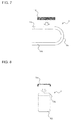
- FIG. 7 is a diagram for explaining a method for mounting the lifetime diagnosis component 10 for anticorrosive coating according to Embodiment to a portion of the heat transfer tube 1, near a hairpin portion 6a.
- FIG. 8 is a diagram of the portion shown in FIG. 7 , as viewed from the hairpin portion 6a side of the heat transfer tube 1, in the direction parallel to the longitudinal direction of the heat transfer tube 1.
- Embodiment shows an example case where the heat exchangers 100 are flat-pipe heat exchangers, which have the flat heat transfer tubes 1.
- FIG. 6 shows a heat exchanger 150 formed by stacking the heat exchangers 100 shown in FIG. 5 in multiple layers, the heat exchangers 100 being formed by connecting the heat transfer tubes 1 to fins 2 and bent in a U shape.
- FIG. 6 shows an example of the heat exchanger 150 in which the heat exchangers 100 are stacked in three layers.
- the heat exchangers 100 each include the heat transfer tubes 1 and the plate-shaped fins 2.
- the heat transfer tubes 1 each have a flow path 1 a (see FIG. 10 ), through which a heat exchange medium flows.
- the heat transfer tube 1 includes straight portions 6A that are inserted into cutaway portions (not shown) provided in the fins 2, the U-shaped hairpin portion 6a continuous with the straight portions 6A and having a flat sectional shape, and aluminum joints 6b connected to ends of the straight portions 6A opposite from the hairpin portion 6a.
- the sectional shape of the straight portions 6A taken in the direction perpendicular to the longitudinal direction thereof, is flat. Note that a header pipe (not shown) is connected to the aluminum joints 6b.
- Fluid such as water, refrigerant, or brine flows through the heat transfer tube 1.
- the heat transfer tube 1 having the hairpin portion 6a with a flat sectional shape is used as the pipe to be inserted into the fins 2
- the configuration is not limited thereto.
- the heat transfer tube 1 having a bent pipe with a circular sectional shape may be used instead of the hairpin portion 6a with a flat sectional shape.
- the position for mounting the lifetime diagnosis component 10 for anticorrosive coating is limited. That is, if the lifetime diagnosis component 10 for anticorrosive coating is mounted to the heat exchanger 100, the fins 2 may be damaged.
- the lifetime diagnosis component 10 for anticorrosive coating is mounted to an end of the straight portion 6A, at a position where the fins 2 are not provided, in the heat transfer tube 1. More specifically, as shown in FIG. 5 , it is desirable that the lifetime diagnosis component 10 for anticorrosive coating be mounted to a portion T1, where the fins 2 are not provided, in the heat transfer tube 1; that is, a portion, in the straight portion 6A, near the hairpin portion 6a.
- the lifetime diagnosis component 10 for anticorrosive coating be mounted to the straight portion 6A between the mounting position, in the straight portion 6A, of the fin 2 closest to the hairpin portion 6a and the position, in the straight portion 6A, where the hairpin portion 6a is joined.
- the lifetime diagnosis component 10 for anticorrosive coating may be mounted to a portion T2 of the heat transfer tube 1 where the fins 2 are not provided. That is, it is desirable that the lifetime diagnosis component 10 for anticorrosive coating be mounted to the portion T2, which is more distant from the hairpin portion 6a than the mounting position, in the straight portion 6A shown in FIG. 5 , of the fin 2 farthest from the hairpin portion 6a. That is, it is desirable that the lifetime diagnosis component 10 for anticorrosive coating be mounted to the portion T2, in the straight portion 6A, which is close to the aluminum joint 6b.
- the lifetime diagnosis component 10 for anticorrosive coating needs to be placed under the same temperature environment as the heat transfer tube of heat exchanger to perform more accurate corrosion diagnosis. Hence, it is desirable that the lifetime diagnosis component 10 for anticorrosive coating be mounted so as to be in close contact with the heat transfer tube 1 of the heat exchanger 100.
- the lifetime diagnosis component 10 for anticorrosive coating By making the lifetime diagnosis component 10 for anticorrosive coating in close contact with the heat exchanger 100, direct heat conduction between the heat transfer tube 1 and the lifetime diagnosis component 10 for anticorrosive coating occurs, making it possible to cause dew condensation on the heat transfer tube 1 and dew condensation on the lifetime diagnosis component 10 for anticorrosive coating at almost the same time.
- An example method for mounting the lifetime diagnosis component 10 for anticorrosive coating will be described below.
- the lifetime diagnosis component 10 for anticorrosive coating When the lifetime diagnosis component 10 for anticorrosive coating is mounted to the straight portion 6A, it is desirable that, as shown in FIGS. 7 and 8 , the ends of the lifetime diagnosis component 10 for anticorrosive coating be bent and that the lifetime diagnosis component 10 for anticorrosive coating be mounted such that it fits the straight portion 6A. By doing so, the lifetime diagnosis component 10 for anticorrosive coating can be mounted to the straight portion 6A so as to be in close contact therewith, without using adhesive or the like. Note that the lifetime diagnosis component 10 for anticorrosive coating may be mounted to the heat transfer tube 1 by using a cord, a wire, or other means.
- the use of adhesive may reduce the rate of heat transfer from the heat transfer tube 1 to the lifetime diagnosis component 10 for anticorrosive coating, making it difficult to establish the same condition for the lifetime diagnosis component 10 for anticorrosive coating and the heat transfer tube 1.
- the adhesive be used within a range in which the influence of the heat conduction is not large. For example, by applying the adhesive not to the whole surface of the lifetime diagnosis component 10 for anticorrosive coating, but only to the peripheral part thereof, the influence on the heat conduction can be reduced.
- water is sprayed from the outside of the housing for the purpose of increasing the heat exchange efficiency.
- the water to be sprayed is, for example, tap water, and the tap water contains ferric ions and copper ions that have lower ionization tendencies than aluminum.
- metal corrosion is influenced by ionization tendency.
- the ferric ions and copper ions contained in tap water and deposited on the surface due to spraying water may accelerate corrosion of aluminum heat exchangers.
- the anticorrosive capacity life diagnosis of the heat exchanger needs to be performed at a portion where the influence of water spray is large. Accordingly, it is desirable that the lifetime diagnosis component 10 for anticorrosive coating be mounted to a portion of the heat transfer tube 1 of the heat exchanger 100 where the influence of water spray is particularly large. Note that the portion where the influence of the water spray is greatest is considered to be a water-spray area W and the vicinity thereof, where wet and dry are frequently changed.
- the outdoor unit 200 according to Embodiment is also provided with a water spraying portion (not shown) at a position facing the rear surface of the heat exchanger 150.
- a water spraying portion (not shown) at a position facing the rear surface of the heat exchanger 150.
- the lifetime diagnosis component 10 for anticorrosive coating be mounted to portions T3 on the rear surface side of the heat exchanger 150. That is, it is desirable that the lifetime diagnosis component 10 for anticorrosive coating be mounted to a peripheral portion W2 of an area (water-spray area W), in the heat exchanger 150, having a certain size and subjected to water supplied from the water spraying portion.
- the peripheral portion is a portion at the boundary between the area on which the water is sprayed and an area on which the water is not sprayed.
- the heat exchanger 150 is formed of the heat exchangers 100 stacked on one another.
- a support member (not shown) for supporting the upper and lower heat exchangers 100 may be mounted to the heat exchangers 100.
- the lifetime diagnosis component 10 for anticorrosive coating may be mounted to the support member such that the lifetime diagnosis component 10 for anticorrosive coating is arranged at the peripheral portion of the water-spray area W.
- the thickness of the first sacrificial anode layer portion 11A and the second sacrificial anode layer portion 11 B be a thickness in a predetermined range, including the thickness of the heat-exchanger sacrificial-anode layer 1A of the heat transfer tube 1. This is because it is easy to diagnose corrosion of the heat exchanger 150 when the condition of the heat exchanger 150 and the condition of the lifetime diagnosis component 10 for anticorrosive coating are the same.
- the thickness of the heat-exchanger sacrificial-anode layer 1A is approximately 85 ⁇ m
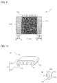
- FIG. 9 is a diagram for explaining the dimensions and the like of the lifetime diagnosis component 10 for anticorrosive coating according to Embodiment.
- FIG. 10(a) is a vertical sectional view of the heat transfer tube 1 of the heat exchanger 100
- FIG. 10(b) is a diagram showing an end of the heat transfer tube 1 shown in FIG. 10(a) .
- FIG. 11 is a diagram for explaining how to ascertain the anticorrosive capacity life of the heat exchanger 100 to which the lifetime diagnosis component 10 for anticorrosive coating is mounted.
- FIG. 12 shows an example corrosion state at a portion of the heat transfer tube 1 of the heat exchanger 100 where zinc is not sprayed. Note that dashed lines A to E in FIG.
- the heat transfer tube 1 of the heat exchanger 100 is provided with the heat-exchanger sacrificial-anode layer 1 A formed of zinc, on the outer surface thereof. Because an aluminum material has lower anticorrosive capacity than a copper material, the heat transfer tube 1, which is an aluminum heat transfer tube, is subjected to zinc spraying, which provides sacrificial corrosion protection, on the surface of the aluminum (A3003) base member thereof to obtain improved anticorrosive capacity.
- the sacrificial corrosion protection is a method of protecting a more noble metal by making an electrically less noble metal selectively corrode, using the electric potential difference between the dissimilar metals.
- the layer of the less noble metal formed when performing sacrificial corrosion protection is called a sacrificial anode layer. Accordingly, by forming the heat-exchanger sacrificial-anode layer 1 A on the heat transfer tube 1, the heat-exchanger sacrificial-anode layer 1 A corrodes instead of the heat transfer tube 1. As a result, corrosion of the heat transfer tube 1 is suppressed.
- the heat-exchanger sacrificial-anode layer 1 A includes a first heat-exchanger sacrificial-anode layer 1A1 formed on the outer surface on one side (i.e., the upper side with respect to the sheet) and a second heat-exchanger sacrificial-anode layer 1 A2 formed on the outer surface on other side (i.e., the lower side with respect to the sheet).
- the first heat-exchanger sacrificial-anode layer 1A1 and the second heat-exchanger sacrificial-anode layer 1 A2 are formed so as to extend in the longitudinal direction of the heat transfer tube 1.
- the first heat-exchanger sacrificial-anode layer 1A1 and the second heat-exchanger sacrificial-anode layer 1 A2 are formed on the outer surface of the heat transfer tube 1 with a predetermined distance therebetween. That is, heat-exchanger base-member-exposed portions 1 B, which are portions where the heat transfer tube 1 is exposed, are provided between the first heat-exchanger sacrificial-anode layer 1A1 and the second heat-exchanger sacrificial-anode layer 1A2.
- the width of the heat-exchanger base-member-exposed portions 1 B that is, the maximum width of the heat transfer tube 1 in the circumferential direction, is 6 mm will be described.
- corrosion of the base-member exposing portion 31 A starts at the position of the line A, which is farthest from the first sacrificial anode layer portion 11A or the second sacrificial anode layer portion 11B, and an area of corrosion expands in the sequence A, B, C .... As the area of corrosion expands, the first sacrificial anode layer portion 11 A and the second sacrificial anode layer portion 11 B recede.
- the corrosion start lines L may be any of the lines B to the lines E.
- the corrosion start lines L are the lines C
- the base-member exposing portion 31 A corrodes at a portion between the line A and the lines C
- the corrosion of the base-member exposing portion 31 A progresses beyond the lines C toward the lines D, it means that the heat transfer tube 1 itself has started to corrode.
- the corrosion start lines L are determined on the basis of the effective area where the sacrificial-corrosion-protection offered by the first sacrificial anode layer portion 11 A and the second sacrificial anode layer portion 11 B is obtained, on the basis of the width of the heat-exchanger base-member-exposed portions 1 B, or the like.
- the corrosion start lines L are set at positions half the width of the initial heat-exchanger base-member-exposed portions 1 B (i.e., X/2) from the first sacrificial anode layer portion 11 A and the second sacrificial anode layer portion 11 B.
- the corrosion start lines L are located somewhere (i.e., the positions of the lines C here) in the area between the center of the base-member exposing portion 31 A (the position of the line A) and the positions 3 mm (X/2) from the first sacrificial anode layer portion 11A and the second sacrificial anode layer portion 11 B.
- the degree of receding of the heat-exchanger sacrificial-anode layer 1 A (the degree of progress of corrosion in the circumferential direction of the heat transfer tube 1) in the actual device (heat exchanger 100) can be known.
- the effective area of the sacrificial-corrosion-protection exists at positions 4 mm to 6 mm away from the ends of the sacrificial anode layer portions 11, and there are certain margins.
- the degree of progress of corrosion in the circumferential direction of the heat transfer tube 1 needs to be determined, taking into consideration the possibility of an error of about ⁇ 1 mm.
- the anticorrosive capacity life of the heat exchanger 100 may be represented by step 1: a first period in which the heat-exchanger sacrificial-anode layer 1 A corrodes, and step 2: a second period in which the heat transfer tube 1 also corrodes. That is, the anticorrosive capacity life may be represented by step 1: the first period from when only the heat-exchanger sacrificial-anode layer 1 A, instead of the heat transfer tube 1, starts to corrode to when the heat transfer tube 1 starts to corrode, and step 2: the second period from when the heat transfer tube 1 starts to corrode to when a through-hole is formed in the heat transfer tube 1.
- the lifetime diagnosis component 10 for anticorrosive coatings By checking the degree of progress of corrosion by collecting the lifetime diagnosis component 10 for anticorrosive coatings at predetermined times (for example, 3 years, 5 years, 8 years, 10 years, and so on), after installation of a refrigeration-and-air-conditioning apparatus in which an actual device (heat exchanger 100) having aluminum heat transfer tubes 1 is provided with the lifetime diagnosis component 10 for anticorrosive coatings, it is possible to diagnose (estimate) the anticorrosive capacity life of the heat exchanger 100. For example, if the corrosion is observed on the line A but not on the lines B, it may be determined that the heat-exchanger sacrificial-anode layer 1 A is corroded, but the heat transfer tube 1 is not yet corroded. This stage corresponds to the first period.
- the progress of corrosion on the outer side of the lines C in FIG. 11 corresponds to the progress of corrosion of the heat-exchanger base-member-exposed portions 1 B in the actual device
- the rate of corrosion of the heat transfer tube 1 in the depth direction can be estimated. That is, it is considered that the more the corrosion of the base-member exposing portion 31 A in the width direction (lateral direction) has progressed, the more the corrosion of base-member exposing portion 31 A in the depth direction has progressed, as shown in FIG. 12 .
- the rate per time of corrosion of the heat-exchanger base-member-exposed portions 1 B of the heat transfer tube 1 in the depth direction can be estimated on the basis of the corrosion of the base-member exposing portion 31 A in the lateral direction. This rate per corrosion of corrosion in the depth direction is used to calculate the second period.
- the first period is estimated from the corrosion of the base-member exposing portion 31 A in the width direction
- the second period is estimated from the corrosion of the base-member exposing portion 31 A in the depth direction.
- the first period which is the time for the corrosion to reach the lines C
- the first period can be calculated on the basis of the rate per time of corrosion, at which the corrosion progresses from the line A to the lines B.
- the rate of corrosion of the heat-exchanger base-member-exposed portions 1 B in the depth direction on the basis of the time taken from the line A to the lines B, it can be determined when a through-hole is likely to be formed in the heat transfer tube 1 because the thickness of the heat transfer tube 1 is known, and the second period can be calculated.
- the anticorrosive capacity life of the heat exchanger 100 can be calculated by adding the calculated first period and second period together,. In this way, the anticorrosive capacity life of the heat transfer tube 1 can be accurately calculated by mounting the lifetime diagnosis component 10 for anticorrosive coatings, checking to which lines the corrosion has reached, and performing predetermined calculations,.
- the corrosion of the base-member exposing portion 31 A in the depth direction may be actually measured to estimate the rate of corrosion of the heat-exchanger base-member-exposed portions 1 B of the heat transfer tube 1 in the depth direction on the basis of the results of measurement.
- Embodiment a case where the initial maximum width (X) of the heat-exchanger base-member-exposed portions 1 B is 6 mm, as described above, has been assumed and described.
- the heat exchanger 100 is produced by zinc spraying, it is difficult to spray zinc on the left and right ends of the heat transfer tube 1 shown in FIG. 10 . That is, due to manufacturing errors or other reasons, zinc may not be sprayed on the corresponding positions of the heat-exchanger base-member-exposed portions 1 B.
- the worst case where zinc is not sprayed on the left and right ends of the heat transfer tube 1, as shown in FIG. 10 is assumed, and the heat-exchanger base-member-exposed portions 1 B have been described as having a width of 6 mm.
- the width of the heat-exchanger base-member-exposed portions 1 B may be 2 mm.
- the corrosion start lines L are located somewhere (i.e., the positions of the lines E here) in the area between the center of the base-member exposing portion 31 A (the position of line A) and the positions at distance of 1 mm (X/2) from each of the first sacrificial anode layer portion 11 A and the second sacrificial anode layer portion 11 B.
- the width of the base-member exposing portion 31 A is set in the range of 8 mm to 12 mm in Embodiment, even when the width of the base-member exposing portion 31 A exceeds 12 mm, the area protected from corrosion, extending from the edges of the first sacrificial anode layer portion 11 A and the second sacrificial anode layer portion 11 B, does not change and remains 4 mm to 6 mm.
- the corrosion protection effect offered by the first sacrificial anode layer portion 11 A and the second sacrificial anode layer portion 11 B cannot be obtained at a portion, of the base-member exposing portion 31 A, at least 6 mm away from each of the first sacrificial anode layer portion 11A and the second sacrificial anode layer portion 11 B.
- corrosion protection effect cannot be obtained corrosion occurs in the same way as on the line A described above. That is, the portion where the corrosion protection effect cannot be obtained is treated in the same way as the line A.
- the lifetime diagnosis component 10 for anticorrosive coatings may be used in the same way as those with the base-member exposing portion 31 A having a width of 8 mm to 12 mm.
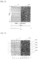
- FIG. 13 is a diagram for explaining a sample used in a test for finding an effective area of the sacrificial corrosion protection.
- FIG. 14 is a diagram showing corrosion-depth measurement points in the sample shown in FIG. 13 .
- FIG. 15 is a diagram for explaining the effective area of a sacrificial anode layer portion 11'.
- FIG. 16 is a diagram showing the sacrificial anode layer portion 11' receded due to corrosion. Referring to FIGS. 13 to 16 , the test performed on the sample according to the lifetime diagnosis component 10 for anticorrosive coating and the results will be described.
- points No.1 to No.5 were defined at equal intervals in the vertical direction, and these points were used as the corrosion-depth measurement points.
- the sample shown in FIG. 13 was further subjected to the corrosion acceleration test, and the depth of corrosion was measured by observing the section in 960 hours and in 2160 hours.
- the presence/absence of an uncorroded part of the sacrificial anode layer portion 11' and the depth of corrosion in the base member 31' at the respective measuring points are shown in Table 3. Note that the presence/absence of the uncorroded part of the sacrificial anode layer portion 11' was determined by observing the section with SEM-EDX.
- SEM refers to a scanning electron microscope
- EDX refers to energy dispersive X-ray analysis.
- a mark "o” represents the presence of the uncorroded part of the sacrificial anode layer portion 11'
- a mark "x” represents the absence of the uncorroded part of the sacrificial anode layer portion 11'
- a mark "-” represents the absence of the uncorroded part of the sacrificial anode layer portion 11' from the beginning.
- the depth of corrosion in the base member at each coordinate is the average of No.1 to No.5.
- the corrosion progresses so as to maintain a distance of at least 4 mm to 6 mm between the edge of the sacrificial anode layer portion 11' and the corrosion in the base member. That is, as shown in FIG. 16 , it is considered that the interface between the sacrificial anode layer portion 11' and the base-member exposing portion 31 A' receded to the left with the progress of corrosion, and a corrosion progress area 38 of the base-member exposing portion 31 A' expanded by the same distance as the distance by which the interface has receded.
- FIG. 17 shows a modification (lifetime diagnosis component for anticorrosive coating 90) of the lifetime diagnosis component 10 for anticorrosive coating according to Embodiment.
- a modification lifetime diagnosis component for anticorrosive coating 90
- the lifetime diagnosis component 10 for anticorrosive coating in which the sacrificial anode layer portions 11 are formed on both sides of the base-member exposing portion 31 A has been described
- a configuration in which a sacrificial anode layer 91 is formed on one side, as shown in FIG. 17 also provides the same advantage as that achieved by the lifetime diagnosis component 10 for anticorrosive coating.
- the lifetime diagnosis component for anticorrosive coating 90 with the sacrificial anode layer 91 formed only on one side of the base-member exposing portion 92 may also be used to diagnose the anticorrosive capacity life.
- the width of the base-member exposing portion 92 exceeds 6 mm, the area, from the edge of the sacrificial anode layer 91, in which corrosion is prevented does not change and remains 4 mm to 6 mm. Accordingly, the corrosion protection effect offered by the sacrificial anode layer 91 cannot be obtained at a portion, of the base-member exposing portion 92, at least 6 mm away from the sacrificial anode layer 91. In such a portion where the corrosion protection effect cannot be obtained, corrosion occurs in the same way as on the line A described above. That is, the portion where the corrosion protection effect cannot be obtained is treated in the same way as the line A.
- the lifetime diagnosis component for anticorrosive coatings 90 may be used in the same way as those with the base-member exposing portion 92 having a width of less than or equal to 6 mm.
- the method is not limited thereto. That is, as long as the sacrificial anode layer portions 11, the base-member exposing portion 31 A, the sacrificial anode layer 91, and the base-member exposing portion 92 having predetermined dimensions can be obtained, as in the lifetime diagnosis component 10 for anticorrosive coating shown in FIG. 9 and the lifetime diagnosis component for anticorrosive coating 90 shown in FIG. 17 , the method is not limited to a method in which the plate member 30 as shown in FIG. 1 is formed and cut.
- the lifetime diagnosis component 10 for anticorrosive coating enables accurate calculation of the anticorrosive capacity life of the heat transfer tube 1 by mounting the lifetime diagnosis component 10 for anticorrosive coating to the heat exchanger 100, checking to which lines the corrosion has reached, and performing predetermined calculations.
- the lifetime diagnosis component 10 for anticorrosive coating according to Embodiment can be easily mounted to a predetermined portion of the heat exchanger 100, taking into consideration the fact that the cause and rate of progress of corrosion of the heat exchanger 100 vary according to the environment in which the heat exchanger 100 is installed.
- the lifetime diagnosis component 10 for anticorrosive coating is a compact plate-shaped member, and hence, it may be mounted either to the peripheral portion (portions T3) of the area (water-spray area W) having a certain size and subjected to water spraying supplied from the water spraying portion or to the portion (portion T1 or portion T2), of the heat transfer tube 1, where the fins 2 are not disposed.
- the lifetime diagnosis component 10 for anticorrosive coating enables accurate diagnosis of anticorrosive capacity life, a serviceperson or other persons can determine appropriate maintenance timing for the heat exchanger 100 and the refrigeration-and-air-conditioning apparatus having the heat exchanger 100. Thus, it is possible to prevent the heat exchanger 100 and the refrigeration-and-air-conditioning apparatus having the heat exchanger 100 from becoming defective due to corrosion, when brought to market.
- 1 heat transfer tube 1 A heat-exchanger sacrificial-anode layer, 1A1 first heat-exchanger sacrificial-anode layer, 1A2 second heat-exchanger sacrificial-anode layer, 1 B heat-exchanger base-member-exposed portion, 1 a flow path, 2 fin, 6A straight portion, 6a hairpin portion, 6b aluminum joint, 10 lifetime diagnosis component for anticorrosive coating, 11 sacrificial anode layer, 11 A first sacrificial anode layer, 11 B second sacrificial anode layer, 11C third sacrificial anode layer, 30 plate member, 31 base member, 31 A base-member exposing portion, 38 corrosion progress area, 51 front panel, 52 side panel, 54 fan guard, 55 air outlet, 56 base panel, 57 compressor, 58 accumulator, 59 air inlet, 90 lifetime diagnosis component for anticorrosive coating, 91 sacrificial anode layer, 92 base-member exposing portion, 100
Landscapes
- Engineering & Computer Science (AREA)
- Chemical & Material Sciences (AREA)
- Life Sciences & Earth Sciences (AREA)
- Mechanical Engineering (AREA)
- Physics & Mathematics (AREA)
- Organic Chemistry (AREA)
- Materials Engineering (AREA)
- General Engineering & Computer Science (AREA)
- Thermal Sciences (AREA)
- Wood Science & Technology (AREA)
- Metallurgy (AREA)
- Health & Medical Sciences (AREA)
- Environmental Sciences (AREA)
- Pathology (AREA)
- General Physics & Mathematics (AREA)
- General Health & Medical Sciences (AREA)
- Biochemistry (AREA)
- Analytical Chemistry (AREA)
- Immunology (AREA)
- Environmental & Geological Engineering (AREA)
- Ecology (AREA)
- Biodiversity & Conservation Biology (AREA)
- Testing Resistance To Weather, Investigating Materials By Mechanical Methods (AREA)
- Prevention Of Electric Corrosion (AREA)
- Other Air-Conditioning Systems (AREA)
- Heat-Exchange Devices With Radiators And Conduit Assemblies (AREA)
Abstract
Description
- The present invention relates to a lifetime diagnosis component for anticorrosive coating, a heat exchanger, and a refrigeration-and-air-conditioning apparatus.
- Conventional heat exchangers used in refrigeration-and-air-conditioning apparatuses have employed copper pipes. However, due to high copper price these days, relatively cheaper alternative materials are required. Under the circumstances, a refrigeration-and-air-conditioning apparatus that employs an aluminum heat exchanger made of an aluminum material, instead of a copper material, has been proposed (for example, see Patent Literature 1).
- Herein, when, for example, a heat exchanger installed in a refrigeration-and-air-conditioning apparatus is serving as an evaporator, air supplied to the heat exchanger is cooled, and dew condensation water is deposited on fins and heat transfer tubes (refrigerant pipes) of the heat exchanger. Because aluminum heat exchangers have lower anticorrosive capacity than copper heat exchangers, the fins and heat transfer tubes of the heat exchangers are corroded by the dew condensation water. If the heat transfer tubes corrode, a through-hole may be formed.
- To suppress this situation, in the technique disclosed in
Patent Literature 1, when a refrigeration-and-air-conditioning apparatus employs an aluminum heat exchanger, a sacrificial anode layer formed of zinc (Zn layer) is formed on the surface of the heat transfer tubes. By allowing the sacrificial anode layer to corrode, corrosion of the heat transfer tubes is suppressed. - Patent Literature 1: Japanese Unexamined Patent Application Publication No.
6-194092 - An aluminum material is cheaper than a copper material, and thus, aluminum heat exchangers are attracting attention as an alternative to conventional copper heat exchangers. However, the aluminum material has lower anticorrosive capacity than the copper material. Hence, when the aluminum material is used for heat transfer tubes of a heat exchanger, a through-hole due to corrosion may be formed in the heat transfer tubes, and refrigerant flowing thorough the heat transfer tubes flow out into the air, which may decrease the heat exchange efficiency of the heat exchanger or place a load on the environment. Hence, the heat exchanger needs to be replaced before the through-hole is formed.
- To prevent the formation of a through-hole due to corrosion in the heat transfer tubes, the anticorrosive capacity life of the heat exchanger needs to be diagnosed (estimated) in advance. However, the cause and rate of progress of corrosion vary according to the environment in which the heat exchanger is installed. Furthermore, depending on the method of forming a sacrificial anode layer, the sacrificial anode layer may not be formed at a position where the sacrificial anode layer is supposed to be formed, due to manufacturing errors or other reasons. Hence, the rate of progress of corrosion varies among heat exchangers.
- As has been described, the cause and rate of progress of corrosion of the heat exchangers vary according to the environment in which the heat exchangers are installed or due to manufacturing errors. Hence, there are uncertainties in diagnosing the anticorrosive capacity life. That is, there is a problem that it is difficult to accurately diagnose the anticorrosive capacity life without deteriorating convenience.
- The present invention has been made to overcome the above-described problem, and an object thereof is to provide a lifetime diagnosis component for anticorrosive coating, a heat exchanger, and a refrigeration-and-air-conditioning apparatus that enable accurate diagnosis of the anticorrosive capacity life, while suppressing deterioration of convenience.
- A lifetime diagnosis component for anticorrosive coating of the present invention includes a plate-shaped base member having, on a surface thereof, an aluminum layer; and a sacrificial anode layer formed of zinc on the base member, the base member having, on the surface thereof, a base-member exposing portion in which the aluminum layer is exposed
- According to the lifetime diagnosis component for anticorrosive coating of the present invention, with the above-described configuration, it is possible to accurately diagnose the anticorrosive capacity life while suppressing deterioration of convenience.
-
- [
FIG. 1] FIG. 1 is a plan view of a plate member, which has lifetime diagnosis component for anticorrosive coatings according to Embodiment of the present invention. - [
FIG. 2] FIG. 2 is a plan view of the lifetime diagnosis component for anticorrosive coating obtained by cutting the plate member shown inFIG. 1 . - [
FIG. 3] FIG. 3 is a perspective view showing the entirety of an outdoor unit, serving as a refrigeration-and-air-conditioning apparatus having the lifetime diagnosis component for anticorrosive coatings. - [
FIG. 4] FIG. 4 is a perspective view of the outdoor unit shown inFIG. 3 , in a state without a front panel, side panels, a fan, a fan guard, etc. - [
FIG. 5] FIG. 5 is a diagram for explaining the mounting positions of the lifetime diagnosis component for anticorrosive coatings according to Embodiment of the present invention. - [
FIG. 6] FIG. 6 is a diagram for explaining the positions, different from those inFIG. 5 , where the lifetime diagnosis component for anticorrosive coatings are mounted. - [
FIG. 7] FIG. 7 is a diagram for explaining a method for mounting the lifetime diagnosis component for anticorrosive coating according to Embodiment of the present invention to a portion of a heat transfer tube, near a hairpin portion. - [
FIG. 8 ] FFIG. 8 is a diagram of the portion shown inFIG. 7 , as viewed from the hairpin portion side, in the direction parallel to the longitudinal direction of the heat transfer tube. - [
FIG. 9] FIG. 9 is a diagram for explaining the dimensions and the like of the lifetime diagnosis component for anticorrosive coating according to Embodiment of the present invention. - [
FIG. 10] FIG. 10(a) is a vertical sectional view of the heat transfer tube of a heat exchanger, andFIG. 10(b) is a diagram showing an end of the heat transfer tube shown inFIG. 10(a) . - [
FIG. 11] FIG. 11 is a diagram for explaining how to ascertain the anticorrosive capacity life of the heat exchanger to which the lifetime diagnosis component for anticorrosive coating is mounted. - [
FIG. 12] FIG. 12 shows an example corrosion state at a portion of the heat transfer tube of the heat exchanger where zinc is not sprayed. - [
FIG. 13] FIG. 13 is a diagram for explaining a sample used in a test for finding an effective area of the sacrificial corrosion protection. - [
FIG. 14] FIG. 14 is a diagram showing corrosion-depth measurement points in the sample shown inFIG. 13 . - [
FIG. 15] FIG. 15 is a diagram for explaining the effective area of the sacrificial anode layer. - [
FIG. 16] FIG. 16 is a diagram showing the sacrificial-anode-layer receded due to corrosion. - [
FIG. 17] FIG. 17 shows a modification of the lifetime diagnosis component for anticorrosive coating according to Embodiment of the present invention. - Hereinbelow, Embodiment of the present invention will be described on the basis of the drawings.
-
FIG. 1 is a plan view of aplate member 30, which haslifetime diagnosis component 10 for anticorrosive coatings according to Embodiment.FIG. 2 is a plan view of thelifetime diagnosis component 10 for anticorrosive coating obtained by cutting theplate member 30 shown inFIG. 1 . Note thatFIG. 2(a) is a plan view of thelifetime diagnosis component 10 for anticorrosive coating, andFIG. 2(b) is a sectional view of thelifetime diagnosis component 10 for anticorrosive coating. InFIGS. 1 and 2(a) , one side of theplate member 30 is shown. - The
plate member 30 includes a plate-shaped base member 31 having an aluminum layer on the surface thereof, and sacrificial anode layer (sacrificial anode layer portions) 11 formed of zinc. Furthermore, theplate member 30 is provided with the sacrificialanode layer portions 11 that are formed by, for example, performing zinc spraying or zinc-containing-material coating on thebase member 31. Note that the sacrificialanode layer portions 11 are formed at portions on one side of theplate member 30. More specifically, as shown inFIG. 1 , the sacrificialanode layer portions 11 are formed at predetermined intervals on one side of theplate member 30. Hence, on one side of theplate member 30, the aluminum layer, serving as thebase member 31, is exposed at portions of thebase member 31 where the sacrificialanode layer portions 11 are not provided. In this manner, the sacrificialanode layer portions 11 and the portions where the aluminum layer, serving as thebase member 31, is exposed (i.e., base-member exposing portions 31 A, described below) are alternately arranged on theplate member 30. Although a configuration in which thebase member 31 having the aluminum layer includes thelifetime diagnosis component 10 for anticorrosive coatings has been described in Embodiment, the configuration is not limited thereto, and an aluminum plate completely composed of aluminum may be used as thebase member 31. - Note that a zinc layer is formed on the other side of the
plate member 30. That is, as shown inFIG. 2(b) , a third sacrificial anode layer 11C formed of zinc is formed on the whole surface on the other side of theplate member 30. The third sacrificial anode layer 11C forms a whole-surface sacrificial-anode layer. Note that this third sacrificial anode layer 11C is also formed by, for example, performing zinc spraying or zinc-containing-material coating. When dissimilar metals are kept in contact with each other for a long time, corrosion is accelerated at the contact surfaces of the dissimilar metals due to the electric potential difference between the metals. Thelifetime diagnosis component 10 for anticorrosive coating is assumed to be mounted to a heat-exchanger sacrificial-anode layer 1 A of aheat transfer tube 1 of a heat exchanger 150 (described below). Thus, the entirety of the rear surface of thelifetime diagnosis component 10 for anticorrosive coating is used as the sacrificial anode to prevent the bimetallic corrosion. - Herein, "zinc spraying" is to spray zinc on the
base member 31. Hence, there is no boundary between the aluminum layer on thebase member 31 and zinc. "Zinc-containing-material coating" is to apply zinc to thebase member 31, and there is a boundary between the aluminum layer on thebase member 31 and zinc.FIG. 2(b) shows a sectional view showing a case where zinc is applied to thebase member 31 by zinc-containing-material coating. Thelifetime diagnosis component 10 for anticorrosive coating according to Embodiment is attached to, for example, a heat exchanger 100 (described below) and is used to diagnose the anticorrosive capacity life of theheat exchanger 100. When diagnosing the anticorrosive capacity life, it is desirable that the condition of thelifetime diagnosis component 10 for anticorrosive coating and the condition of theheat exchanger 100 be the same. Hence, when theheat exchanger 100 is produced by zinc spraying, thelifetime diagnosis component 10 for anticorrosive coating should also be produced by zinc spraying, and when theheat exchanger 100 is produced by zinc-containing-material coating, thelifetime diagnosis component 10 for anticorrosive coating should also be produced by zinc-containing-material coating. - The
lifetime diagnosis component 10 for anticorrosive coating is obtained by cutting theplate member 30, as shown inFIG. 1 . That is, by cutting theplate member 30 along dashed lines shown inFIG. 1 , portions of theplate member 30 delimited by the dashed lines are cut away, and thelifetime diagnosis component 10 for anticorrosive coating can be obtained. - The
lifetime diagnosis component 10 for anticorrosive coating is provided with multiple strip-shaped sacrificialanode layer portions 11. Specifically, thelifetime diagnosis component 10 for anticorrosive coating is provided with a first sacrificialanode layer portion 11 A formed at one end and a second sacrificialanode layer portion 11 B formed at the other end. The base-member exposing portion 31 A, which is a portion where thebase member 31 is exposed, is provided between the first sacrificialanode layer portion 11 A and the second sacrificialanode layer portion 11 B. In this manner, on one side of thelifetime diagnosis component 10 for anticorrosive coating, the base-member exposing portion 31 A is located between the first sacrificialanode layer portion 11 A and the second sacrificialanode layer portion 11 B. Note that the third sacrificial anode layer 11C including the zinc layer is formed on the entire other side of thelifetime diagnosis component 10 for anticorrosive coating. Thelifetime diagnosis component 10 for anticorrosive coating is mounted to aheat transfer tube 1 such that the other surface of the base member, which is the surface with the third sacrificial anode layer 11C, comes into contact with the outer surface of theheat transfer tube 1. - The first sacrificial
anode layer portion 11 A and the second sacrificialanode layer portion 11 B have a width, in the direction parallel to the direction from one side to the other side of thebase member 31, of 5 mm or more, and the base-member exposing portion 31 A has a width, in the direction parallel to the direction from one side to the other side of thebase member 31, of 8 mm to 12 mm (seeFIG. 9 ). Note that the reason why the width in the direction parallel to the direction from one side to the other side of thebase member 31 is set to 8 mm to 12 mm will be described in detail inFIGS. 13 and 14 below. - Note that, although an example case where the
plate member 30 includes thebase member 31 having the aluminum layer and where thelifetime diagnosis component 10 for anticorrosive coating is obtained by performing zinc spraying or zinc-containing-material coating has been described in Embodiment, the configuration is not limited thereto. For example, it is also possible to use a clad plate formed by bonding an aluminum plate member and zinc plate members. That is, a clad plate formed by bonding zinc plate members, corresponding to the first sacrificialanode layer portion 11 A and the second sacrificialanode layer portion 11 B, with an aluminum plate member, corresponding to thebase member 31, may be used. Furthermore, this clad plate may have three layers by additionally including a zinc plate member corresponding to the third sacrificial anode layer 11C. Note that, when a clad plate is used, the aluminum layer is disposed on one side of theplate member 30, so that the base-member exposing portion 31 A is the aluminum layer. -
FIG. 3 is a perspective view showing the entirety of anoutdoor unit 200, serving as a refrigeration-and-air-conditioning apparatus having thelifetime diagnosis component 10 for anticorrosive coatings.FIG. 4 is a perspective view of theoutdoor unit 200 shown inFIG. 3 , in a state with afront panel 51, aside panel 52, a fan, afan guard 54, etc. having been removed. An example of the refrigeration-and-air-conditioning apparatus will be described by taking theoutdoor unit 200 of the air-conditioning apparatus as an example. - The
outdoor unit 200 has, for example, a vertically long housing. That is, as shown inFIG. 3 , theoutdoor unit 200 includes thefront panel 51 that forms a housing on the front side of theoutdoor unit 200, thefan guard 54 provided at the top of theoutdoor unit 200, and theside panel 52 that forms the housing on the sides of theoutdoor unit 200. Theoutdoor unit 200 is provided withair inlets 59, through which air is taken in, in the side surfaces and rear surface of the housing and is provided with anair outlet 55, through which the air is discharged outside, at the top of theoutdoor unit 200. That is, theoutdoor unit 200 has theair inlets 59, which are provided in theside panel 52 and used to take air into theoutdoor unit 200, and theair outlet 55, which is provided in thefan guard 54 and used to discharge the air inside theoutdoor unit 200 to the outside of theoutdoor unit 200. - The
outdoor unit 200 includes theheat exchangers 100, abase panel 56 that supports theheat exchangers 100, acompressor 57 that compresses and discharges the refrigerant, and anaccumulator 58 that stores excess refrigerant. - The
heat exchangers 100 cause the refrigerant supplied thereto and the air passing therethrough to exchange heat. During a cooling-mode operation, theheat exchangers 100 function as a condenser (radiator) to condense and liquefy the refrigerant, whereas during a heating-mode operation, theheat exchangers 100 function as an evaporator to evaporate and gasify the refrigerant. Theheat exchangers 100 are provided at positions facing theside panel 52 and fixed to, for example, theside panel 52. - Herein, although the
heat exchangers 100 are described as being vertically stacked in three layers in Embodiment, the configuration of theheat exchangers 100 is not limited thereto; a configuration in which theheat exchangers 100 are not stacked is also possible. - The
base panel 56 supports theheat exchangers 100, thecompressor 57, theaccumulator 58, and other components, and these components are fastened to thebase panel 56 with, for example, screws. Thebase panel 56 constitutes the housing of theoutdoor unit 200 on the bottom side. Thecompressor 57 is disposed on, for example, thebase panel 56 and compresses and discharges the refrigerant. Thecompressor 57 is coupled to theaccumulator 58 at the suction side thereof. Furthermore, the discharge side of thecompressor 57 is coupled to theheat exchangers 100 during a cooling-mode operation and is coupled to a use-side heat exchanger installed in an indoor unit (not shown) during a heating-mode operation. Theaccumulator 58 is coupled to the suction side of thecompressor 57 and stores liquid refrigerant. Furthermore, theheat exchangers 100 are provided vertically on the rear side, right side, and left side of theaccumulator 58. - Furthermore, the
outdoor unit 200 is provided with a fan (not shown) used to take air into theoutdoor unit 200 and to discharge the air. Note that the fan is exposed by removing thefan guard 54. The fan takes air into theoutdoor unit 200 and discharges the air outside theoutdoor unit 200 by rotating. The fan is provided so as to be surrounded by thefan guard 54 in this manner, and theair outlet 55 is formed above the fan. That is, the air passing through theheat exchangers 100 arranged along theair inlets 59 is drawn into the inside of theoutdoor unit 200 and is discharged, through the fan, from theair outlet 55 provided in the housing, at the top. -
FIG. 5 is a diagram for explaining the mounting positions of thelifetime diagnosis component 10 for anticorrosive coatings according to Embodiment.FIG. 6 is a diagram for explaining the positions, different from those inFIG. 5 , where thelifetime diagnosis component 10 for anticorrosive coatings is mounted.FIG. 7 is a diagram for explaining a method for mounting thelifetime diagnosis component 10 for anticorrosive coating according to Embodiment to a portion of theheat transfer tube 1, near ahairpin portion 6a.FIG. 8 is a diagram of the portion shown inFIG. 7 , as viewed from thehairpin portion 6a side of theheat transfer tube 1, in the direction parallel to the longitudinal direction of theheat transfer tube 1. - Note that Embodiment shows an example case where the
heat exchangers 100 are flat-pipe heat exchangers, which have the flatheat transfer tubes 1. Furthermore,FIG. 6 shows a heat exchanger 150 formed by stacking theheat exchangers 100 shown inFIG. 5 in multiple layers, theheat exchangers 100 being formed by connecting theheat transfer tubes 1 tofins 2 and bent in a U shape.FIG. 6 shows an example of the heat exchanger 150 in which theheat exchangers 100 are stacked in three layers. - As shown in
FIGS. 5 and 6 , theheat exchangers 100 each include theheat transfer tubes 1 and the plate-shapedfins 2. Theheat transfer tubes 1 each have a flow path 1 a (seeFIG. 10 ), through which a heat exchange medium flows. Theheat transfer tube 1 includesstraight portions 6A that are inserted into cutaway portions (not shown) provided in thefins 2, theU-shaped hairpin portion 6a continuous with thestraight portions 6A and having a flat sectional shape, and aluminum joints 6b connected to ends of thestraight portions 6A opposite from thehairpin portion 6a. The sectional shape of thestraight portions 6A, taken in the direction perpendicular to the longitudinal direction thereof, is flat. Note that a header pipe (not shown) is connected to the aluminum joints 6b. Fluid, such as water, refrigerant, or brine, flows through theheat transfer tube 1. Note that, although an example case where theheat transfer tube 1 having thehairpin portion 6a with a flat sectional shape is used as the pipe to be inserted into thefins 2 will be described in Embodiment, the configuration is not limited thereto. For example, theheat transfer tube 1 having a bent pipe with a circular sectional shape may be used instead of thehairpin portion 6a with a flat sectional shape. - There are
multiple fins 2 joined to theheat transfer tube 1, and therefore, the position for mounting thelifetime diagnosis component 10 for anticorrosive coating is limited. That is, if thelifetime diagnosis component 10 for anticorrosive coating is mounted to theheat exchanger 100, thefins 2 may be damaged. Hence, as shown inFIG. 5 , thelifetime diagnosis component 10 for anticorrosive coating is mounted to an end of thestraight portion 6A, at a position where thefins 2 are not provided, in theheat transfer tube 1. More specifically, as shown inFIG. 5 , it is desirable that thelifetime diagnosis component 10 for anticorrosive coating be mounted to a portion T1, where thefins 2 are not provided, in theheat transfer tube 1; that is, a portion, in thestraight portion 6A, near thehairpin portion 6a. More specifically, it is desirable that thelifetime diagnosis component 10 for anticorrosive coating be mounted to thestraight portion 6A between the mounting position, in thestraight portion 6A, of thefin 2 closest to thehairpin portion 6a and the position, in thestraight portion 6A, where thehairpin portion 6a is joined. - Alternatively, as shown in
FIG. 5 , thelifetime diagnosis component 10 for anticorrosive coating may be mounted to a portion T2 of theheat transfer tube 1 where thefins 2 are not provided. That is, it is desirable that thelifetime diagnosis component 10 for anticorrosive coating be mounted to the portion T2, which is more distant from thehairpin portion 6a than the mounting position, in thestraight portion 6A shown inFIG. 5 , of thefin 2 farthest from thehairpin portion 6a. That is, it is desirable that thelifetime diagnosis component 10 for anticorrosive coating be mounted to the portion T2, in thestraight portion 6A, which is close to the aluminum joint 6b. - When the heat exchanger installed in the refrigeration-and-air-conditioning apparatus is used in a low-temperature side, dew condensation occurs. That is, when the heat exchanger is serving as an evaporator, the water density in the air is supersaturated, and dew condenses on the heat exchanger. Because the dew condensation water deposited on the surface of the heat exchanger may accelerate corrosion, the
lifetime diagnosis component 10 for anticorrosive coating needs to be placed under the same temperature environment as the heat transfer tube of heat exchanger to perform more accurate corrosion diagnosis. Hence, it is desirable that thelifetime diagnosis component 10 for anticorrosive coating be mounted so as to be in close contact with theheat transfer tube 1 of theheat exchanger 100. By making thelifetime diagnosis component 10 for anticorrosive coating in close contact with theheat exchanger 100, direct heat conduction between theheat transfer tube 1 and thelifetime diagnosis component 10 for anticorrosive coating occurs, making it possible to cause dew condensation on theheat transfer tube 1 and dew condensation on thelifetime diagnosis component 10 for anticorrosive coating at almost the same time. An example method for mounting thelifetime diagnosis component 10 for anticorrosive coating will be described below. - When the
lifetime diagnosis component 10 for anticorrosive coating is mounted to thestraight portion 6A, it is desirable that, as shown inFIGS. 7 and 8 , the ends of thelifetime diagnosis component 10 for anticorrosive coating be bent and that thelifetime diagnosis component 10 for anticorrosive coating be mounted such that it fits thestraight portion 6A. By doing so, thelifetime diagnosis component 10 for anticorrosive coating can be mounted to thestraight portion 6A so as to be in close contact therewith, without using adhesive or the like. Note that thelifetime diagnosis component 10 for anticorrosive coating may be mounted to theheat transfer tube 1 by using a cord, a wire, or other means. - Herein, although a method using adhesive or other means may be an option, it should be noted that the use of adhesive may reduce the rate of heat transfer from the
heat transfer tube 1 to thelifetime diagnosis component 10 for anticorrosive coating, making it difficult to establish the same condition for thelifetime diagnosis component 10 for anticorrosive coating and theheat transfer tube 1. Hence, it is preferable that, when adhesive is used, the adhesive be used within a range in which the influence of the heat conduction is not large. For example, by applying the adhesive not to the whole surface of thelifetime diagnosis component 10 for anticorrosive coating, but only to the peripheral part thereof, the influence on the heat conduction can be reduced. - Moreover, in some heat exchangers installed in the outdoor units of refrigeration-and-air-conditioning apparatuses, water is sprayed from the outside of the housing for the purpose of increasing the heat exchange efficiency. The water to be sprayed is, for example, tap water, and the tap water contains ferric ions and copper ions that have lower ionization tendencies than aluminum. Meanwhile, metal corrosion is influenced by ionization tendency. When metals having different ionization tendencies come into contact with each other, the metal having higher ionization tendency preferentially corrodes. Thus, the ferric ions and copper ions contained in tap water and deposited on the surface due to spraying water may accelerate corrosion of aluminum heat exchangers. Hence, the anticorrosive capacity life diagnosis of the heat exchanger needs to be performed at a portion where the influence of water spray is large. Accordingly, it is desirable that the
lifetime diagnosis component 10 for anticorrosive coating be mounted to a portion of theheat transfer tube 1 of theheat exchanger 100 where the influence of water spray is particularly large. Note that the portion where the influence of the water spray is greatest is considered to be a water-spray area W and the vicinity thereof, where wet and dry are frequently changed. - Herein, the
outdoor unit 200 according to Embodiment is also provided with a water spraying portion (not shown) at a position facing the rear surface of the heat exchanger 150. Hence, as shown inFIG. 6 , it is desirable that thelifetime diagnosis component 10 for anticorrosive coating be mounted to portions T3 on the rear surface side of the heat exchanger 150. That is, it is desirable that thelifetime diagnosis component 10 for anticorrosive coating be mounted to a peripheral portion W2 of an area (water-spray area W), in the heat exchanger 150, having a certain size and subjected to water supplied from the water spraying portion. Note that the peripheral portion is a portion at the boundary between the area on which the water is sprayed and an area on which the water is not sprayed. Herein, the heat exchanger 150 is formed of theheat exchangers 100 stacked on one another. Hence, a support member (not shown) for supporting the upper andlower heat exchangers 100 may be mounted to theheat exchangers 100. Thus, thelifetime diagnosis component 10 for anticorrosive coating may be mounted to the support member such that thelifetime diagnosis component 10 for anticorrosive coating is arranged at the peripheral portion of the water-spray area W. - Furthermore, it is desirable that the thickness of the first sacrificial
anode layer portion 11A and the second sacrificialanode layer portion 11 B be a thickness in a predetermined range, including the thickness of the heat-exchanger sacrificial-anode layer 1A of theheat transfer tube 1. This is because it is easy to diagnose corrosion of the heat exchanger 150 when the condition of the heat exchanger 150 and the condition of thelifetime diagnosis component 10 for anticorrosive coating are the same. Hence, for example, when the thickness of the heat-exchanger sacrificial-anode layer 1A is approximately 85 µm, it is desirable that the thickness of the first sacrificialanode layer portion 11A and the second sacrificialanode layer portion 11 B be set to, for example, approximately 75 µm to 100 µm. -
FIG. 9 is a diagram for explaining the dimensions and the like of thelifetime diagnosis component 10 for anticorrosive coating according to Embodiment.FIG. 10(a) is a vertical sectional view of theheat transfer tube 1 of theheat exchanger 100, andFIG. 10(b) is a diagram showing an end of theheat transfer tube 1 shown inFIG. 10(a) .FIG. 11 is a diagram for explaining how to ascertain the anticorrosive capacity life of theheat exchanger 100 to which thelifetime diagnosis component 10 for anticorrosive coating is mounted.FIG. 12 shows an example corrosion state at a portion of theheat transfer tube 1 of theheat exchanger 100 where zinc is not sprayed. Note that dashed lines A to E inFIG. 9 are used to diagnose (estimate) the time when theheat transfer tube 1 of theheat exchanger 100 to which thelifetime diagnosis component 10 for anticorrosive coating is mounted will start corroding. Furthermore, black dots on the dashed lines A to E show measuring points, where measurement as to whether corrosion has occurred is conducted. - As shown in
FIG. 10 , theheat transfer tube 1 of theheat exchanger 100 is provided with the heat-exchanger sacrificial-anode layer 1 A formed of zinc, on the outer surface thereof. Because an aluminum material has lower anticorrosive capacity than a copper material, theheat transfer tube 1, which is an aluminum heat transfer tube, is subjected to zinc spraying, which provides sacrificial corrosion protection, on the surface of the aluminum (A3003) base member thereof to obtain improved anticorrosive capacity. The sacrificial corrosion protection is a method of protecting a more noble metal by making an electrically less noble metal selectively corrode, using the electric potential difference between the dissimilar metals. That is, in the aluminum heat exchanger, to protect the aluminum (more noble) base from corrosion, zinc (less noble) is sprayed on the aluminum surface, and zinc is made to preferentially corrode. Note that the layer of the less noble metal formed when performing sacrificial corrosion protection is called a sacrificial anode layer. Accordingly, by forming the heat-exchanger sacrificial-anode layer 1 A on theheat transfer tube 1, the heat-exchanger sacrificial-anode layer 1 A corrodes instead of theheat transfer tube 1. As a result, corrosion of theheat transfer tube 1 is suppressed. - As shown in
FIG. 10 , in a vertical sectional view of theheat transfer tube 1, the heat-exchanger sacrificial-anode layer 1 A includes a first heat-exchanger sacrificial-anode layer 1A1 formed on the outer surface on one side (i.e., the upper side with respect to the sheet) and a second heat-exchanger sacrificial-anode layer 1 A2 formed on the outer surface on other side (i.e., the lower side with respect to the sheet). The first heat-exchanger sacrificial-anode layer 1A1 and the second heat-exchanger sacrificial-anode layer 1 A2 are formed so as to extend in the longitudinal direction of theheat transfer tube 1. The first heat-exchanger sacrificial-anode layer 1A1 and the second heat-exchanger sacrificial-anode layer 1 A2 are formed on the outer surface of theheat transfer tube 1 with a predetermined distance therebetween. That is, heat-exchanger base-member-exposedportions 1 B, which are portions where theheat transfer tube 1 is exposed, are provided between the first heat-exchanger sacrificial-anode layer 1A1 and the second heat-exchanger sacrificial-anode layer 1A2. In Embodiment, an example case where the width of the heat-exchanger base-member-exposedportions 1 B, that is, the maximum width of theheat transfer tube 1 in the circumferential direction, is 6 mm will be described. - With the
lifetime diagnosis component 10 for anticorrosive coating according to Embodiment, it is confirmed that, at positions within 5 mm from the first sacrificialanode layer portion 11 A and the second sacrificialanode layer portion 11 B, corrosion of the base-member exposing portion 31 A is suppressed due to the effect of the sacrificial corrosion protection. That is, corrosion of the base-member exposing portion 31 A starts at a position, in the base-member exposing portion 31 A, far from the first sacrificialanode layer portion 11 A or the second sacrificialanode layer portion 11 B. Hence, corrosion of the base-member exposing portion 31 A starts at the position of the line A, which is farthest from the first sacrificialanode layer portion 11A or the second sacrificialanode layer portion 11B, and an area of corrosion expands in the sequence A, B, C .... As the area of corrosion expands, the first sacrificialanode layer portion 11 A and the second sacrificialanode layer portion 11 B recede. - When the corrosion of the base-
member exposing portion 31 A progresses, and the corrosion of the base-member exposing portion 31 A reaches corrosion start lines L, which show that theheat transfer tube 1 of theheat exchanger 100 itself starts to corrode, a serviceperson or what is in the similar role can determine that theheat transfer tube 1 itself has started to corrode. Herein, the corrosion start lines L may be any of the lines B to the lines E. For example, when the corrosion start lines L are the lines C, while the base-member exposing portion 31 A corrodes at a portion between the line A and the lines C, it means that theheat transfer tube 1 itself is not corroded, but the heat-exchanger sacrificial-anode layer 1 A is corroded. Then, when the corrosion of the base-member exposing portion 31 A progresses beyond the lines C toward the lines D, it means that theheat transfer tube 1 itself has started to corrode. - The corrosion start lines L are determined on the basis of the effective area where the sacrificial-corrosion-protection offered by the first sacrificial
anode layer portion 11 A and the second sacrificialanode layer portion 11 B is obtained, on the basis of the width of the heat-exchanger base-member-exposedportions 1 B, or the like. When the initial maximum width (X) of the heat-exchanger base-member-exposedportions 1 B of the actual device (heat exchanger 100) and the initial width of the base-member exposing portion 31 A of thelifetime diagnosis component 10 for anticorrosive coating are different, the corrosion start lines L are set at positions half the width of the initial heat-exchanger base-member-exposedportions 1 B (i.e., X/2) from the first sacrificialanode layer portion 11 A and the second sacrificialanode layer portion 11 B. - For example, when the initial maximum width (X) of the heat-exchanger base-member-exposed
portions 1 B assumed in the actual device is 6 mm, as shown inFIG. 10(b) , the corrosion start lines L are located somewhere (i.e., the positions of the lines C here) in the area between the center of the base-member exposing portion 31 A (the position of the line A) and thepositions 3 mm (X/2) from the first sacrificialanode layer portion 11A and the second sacrificialanode layer portion 11 B. Then, by checking the presence/absence of corrosion of the base-member exposing portion 31 A on the line A and lines B, which are on the inner side of the lines C, serving as the corrosion start lines L, the degree of receding of the heat-exchanger sacrificial-anode layer 1 A (the degree of progress of corrosion in the circumferential direction of the heat transfer tube 1) in the actual device (heat exchanger 100) can be known. - Note that, however, as will be described by referring to the tests and the results described in
FIGS. 13 to 16 and Tables 1 to 3, the effective area of the sacrificial-corrosion-protection exists atpositions 4 mm to 6 mm away from the ends of the sacrificialanode layer portions 11, and there are certain margins. Hence, for example, the degree of progress of corrosion in the circumferential direction of theheat transfer tube 1 needs to be determined, taking into consideration the possibility of an error of about ± 1 mm. - Herein, the anticorrosive capacity life of the
heat exchanger 100 may be represented by step 1: a first period in which the heat-exchanger sacrificial-anode layer 1 A corrodes, and step 2: a second period in which theheat transfer tube 1 also corrodes. That is, the anticorrosive capacity life may be represented by step 1: the first period from when only the heat-exchanger sacrificial-anode layer 1 A, instead of theheat transfer tube 1, starts to corrode to when theheat transfer tube 1 starts to corrode, and step 2: the second period from when theheat transfer tube 1 starts to corrode to when a through-hole is formed in theheat transfer tube 1. - By checking the degree of progress of corrosion by collecting the
lifetime diagnosis component 10 for anticorrosive coatings at predetermined times (for example, 3 years, 5 years, 8 years, 10 years, and so on), after installation of a refrigeration-and-air-conditioning apparatus in which an actual device (heat exchanger 100) having aluminumheat transfer tubes 1 is provided with thelifetime diagnosis component 10 for anticorrosive coatings, it is possible to diagnose (estimate) the anticorrosive capacity life of theheat exchanger 100. For example, if the corrosion is observed on the line A but not on the lines B, it may be determined that the heat-exchanger sacrificial-anode layer 1 A is corroded, but theheat transfer tube 1 is not yet corroded. This stage corresponds to the first period. - Moreover, because the progress of corrosion on the outer side of the lines C in
FIG. 11 corresponds to the progress of corrosion of the heat-exchanger base-member-exposedportions 1 B in the actual device, by checking the degree of progress of corrosion on the line A and the lines B at the time when the corrosion has started on the lines C, the rate of corrosion of theheat transfer tube 1 in the depth direction can be estimated. That is, it is considered that the more the corrosion of the base-member exposing portion 31 A in the width direction (lateral direction) has progressed, the more the corrosion of base-member exposing portion 31 A in the depth direction has progressed, as shown inFIG. 12 . Hence, the rate per time of corrosion of the heat-exchanger base-member-exposedportions 1 B of theheat transfer tube 1 in the depth direction can be estimated on the basis of the corrosion of the base-member exposing portion 31 A in the lateral direction. This rate per corrosion of corrosion in the depth direction is used to calculate the second period. - In this way, the first period is estimated from the corrosion of the base-
member exposing portion 31 A in the width direction, and the second period is estimated from the corrosion of the base-member exposing portion 31 A in the depth direction. By doing so, the anticorrosive capacity life of theheat exchanger 100 can be diagnosed. - For example, if the corrosion of the base-
member exposing portion 31 A has reached the lines B, serving as the corrosion start lines L, the first period, which is the time for the corrosion to reach the lines C, can be calculated on the basis of the rate per time of corrosion, at which the corrosion progresses from the line A to the lines B. Furthermore, by estimating the rate of corrosion of the heat-exchanger base-member-exposedportions 1 B in the depth direction on the basis of the time taken from the line A to the lines B, it can be determined when a through-hole is likely to be formed in theheat transfer tube 1 because the thickness of theheat transfer tube 1 is known, and the second period can be calculated. The anticorrosive capacity life of theheat exchanger 100 can be calculated by adding the calculated first period and second period together,. In this way, the anticorrosive capacity life of theheat transfer tube 1 can be accurately calculated by mounting thelifetime diagnosis component 10 for anticorrosive coatings, checking to which lines the corrosion has reached, and performing predetermined calculations,. - Needless to say, the corrosion of the base-
member exposing portion 31 A in the depth direction may be actually measured to estimate the rate of corrosion of the heat-exchanger base-member-exposedportions 1 B of theheat transfer tube 1 in the depth direction on the basis of the results of measurement. - Furthermore, in Embodiment, a case where the initial maximum width (X) of the heat-exchanger base-member-exposed
portions 1 B is 6 mm, as described above, has been assumed and described. Herein, when theheat exchanger 100 is produced by zinc spraying, it is difficult to spray zinc on the left and right ends of theheat transfer tube 1 shown inFIG. 10 . That is, due to manufacturing errors or other reasons, zinc may not be sprayed on the corresponding positions of the heat-exchanger base-member-exposedportions 1 B. Hence, in Embodiment, the worst case where zinc is not sprayed on the left and right ends of theheat transfer tube 1, as shown inFIG. 10 , is assumed, and the heat-exchanger base-member-exposedportions 1 B have been described as having a width of 6 mm. - Hence, if zinc spraying is appropriately performed, the width of the heat-exchanger base-member-exposed
portions 1 B may be 2 mm. In such a case, the corrosion start lines L are located somewhere (i.e., the positions of the lines E here) in the area between the center of the base-member exposing portion 31 A (the position of line A) and the positions at distance of 1 mm (X/2) from each of the first sacrificialanode layer portion 11 A and the second sacrificialanode layer portion 11 B. - Furthermore, although the width of the base-
member exposing portion 31 A is set in the range of 8 mm to 12 mm in Embodiment, even when the width of the base-member exposing portion 31 A exceeds 12 mm, the area protected from corrosion, extending from the edges of the first sacrificialanode layer portion 11 A and the second sacrificialanode layer portion 11 B, does not change and remains 4 mm to 6 mm. Accordingly, the corrosion protection effect offered by the first sacrificialanode layer portion 11 A and the second sacrificialanode layer portion 11 B cannot be obtained at a portion, of the base-member exposing portion 31 A, at least 6 mm away from each of the first sacrificialanode layer portion 11A and the second sacrificialanode layer portion 11 B. In such a portion where the corrosion protection effect cannot be obtained, corrosion occurs in the same way as on the line A described above. That is, the portion where the corrosion protection effect cannot be obtained is treated in the same way as the line A. Even in the case like this where the width of the base-member exposing portion 31 A exceeds 12 mm, thelifetime diagnosis component 10 for anticorrosive coatings may be used in the same way as those with the base-member exposing portion 31 A having a width of 8 mm to 12 mm. -
FIG. 13 is a diagram for explaining a sample used in a test for finding an effective area of the sacrificial corrosion protection.FIG. 14 is a diagram showing corrosion-depth measurement points in the sample shown inFIG. 13 .FIG. 15 is a diagram for explaining the effective area of a sacrificial anode layer portion 11'.FIG. 16 is a diagram showing the sacrificial anode layer portion 11' receded due to corrosion. Referring toFIGS. 13 to 16 , the test performed on the sample according to thelifetime diagnosis component 10 for anticorrosive coating and the results will be described. - As shown in
FIG. 13 , a sample for corrosion acceleration test, which was an aluminum plate having a size of 20 mm x 20 mm with a sacrificial anode (sprayed zinc) layer having a size of 10 mm x 20 mm formed to a thickness of 75 µm to 100 µm on the left half thereof, was prepared. Note that the coordinates were defined by assuming the interface between a base-member exposing portion 31 A' and the sacrificial anode layer portion 11' to be x = 0, the base-member exposing portion 31 A' side to be positive, and the sacrificial anode layer portion 11' side to be negative. - Furthermore, as shown in
FIG. 14 , at each of the coordinates with x = -8, - 6, -4, -2, 0, 2, 4, 6, and 8, points No.1 to No.5 were defined at equal intervals in the vertical direction, and these points were used as the corrosion-depth measurement points. - A corrosion acceleration test with n = 5 was performed on the sample shown in
FIG. 13 according to the combined cyclic corrosion test shown in Table 1.[Table 1] METHOD OF TEST CONDITIONS OF TEST 1. SPRAY TEMPERATURE 35 ±1 degree(s) Celsius SPRAY LIQUID Corrosive Liquid (chloride ion concentration: equivalent to 5% NaCl SOLUTION, pH = 7) 2. DRY TEMPERATURE 60 ±1 degree(s) Celsius RELATIVE HUMIDITY 20 - 30 %RH 3. WET HUMIDITY 50 ±1 degree(s) Celsius RELATIVE HUMIDITY 95%RH or more 4. TIME AND CONTENT PER CYCLE SPRAY: 2h, DRY: 4h, WET: 2h - After 480 hours, the section of the sample for corrosion acceleration test was observed. The results of measurement of the depth of corrosion in the base member are shown in Table 2. In No.1, the base member corroded by 2 mm at x = 6 mm and by 5 mm at x = 8 mm. In No.2, the base member corroded by 4 mm at x = 8 mm. In No.3, the base member corroded by 1 mm at x = 6 mm and by 6 mm at x = 8 mm. In No.4, the base member corroded by 6 mm at x = 8 mm. In No.5, the base member corroded by 7 mm at x = 8 mm.
- From above, the base member did not corrode at all in x = -8 mm to 4 mm. Furthermore, at x = 6 mm, the corrosion of the base member had progressed in No.1 and No. 3. That is, from the fact that the corrosion of the base member had not progressed at positions within 4 mm to 6 mm from the interface with respect to the sacrificial anode layer portion 11' of the sample, it is thought that, as shown in
FIG. 15 , sacrificial corrosion protection is effective within 4 mm to 6 mm from the edge of the sacrificial anode layer portion 11'.[Table 2] No. x[mm] -8 -6 -4 -2 0 2 4 6 8 1 0 0 0 0 0 0 0 2 5 2 0 0 0 0 0 0 0 0 4 3 0 0 0 0 0 0 0 1 6 4 0 0 0 0 0 0 0 0 6 5 0 0 0 0 0 0 0 0 7 - The sample shown in
FIG. 13 was further subjected to the corrosion acceleration test, and the depth of corrosion was measured by observing the section in 960 hours and in 2160 hours. The presence/absence of an uncorroded part of the sacrificial anode layer portion 11' and the depth of corrosion in the base member 31' at the respective measuring points are shown in Table 3. Note that the presence/absence of the uncorroded part of the sacrificial anode layer portion 11' was determined by observing the section with SEM-EDX. Herein, SEM refers to a scanning electron microscope, and EDX refers to energy dispersive X-ray analysis. By checking the presence/absence of the uncorroded part of the sacrificial anode layer portion 11' (zinc layer) at the respective measuring points with the SEM-EDX, the depth of corrosion was determined. Herein, in Table 3, a mark "o" represents the presence of the uncorroded part of the sacrificial anode layer portion 11', a mark "x" represents the absence of the uncorroded part of the sacrificial anode layer portion 11', and a mark "-" represents the absence of the uncorroded part of the sacrificial anode layer portion 11' from the beginning. Furthermore, the depth of corrosion in the base member at each coordinate is the average of No.1 to No.5. - In 480 hours, there was the uncorroded part of the sacrificial anode layer portion 11' at x = 0 mm. At x = 6 mm, the base member corroded by 1 mm.
- In 960 hours, there was the uncorroded part of the sacrificial anode layer portion 11' at x = -4 mm. At x = 2 mm, the base member corroded by 4 mm.
- In 2160 h, there was the uncorroded part of the sacrificial anode layer portion 11' at x = -8 mm. At x = -2 mm, the base member corroded by 3 mm.
- From above, it is considered that the corrosion progresses so as to maintain a distance of at least 4 mm to 6 mm between the edge of the sacrificial anode layer portion 11' and the corrosion in the base member. That is, as shown in
FIG. 16 , it is considered that the interface between the sacrificial anode layer portion 11' and the base-member exposing portion 31 A' receded to the left with the progress of corrosion, and acorrosion progress area 38 of the base-member exposing portion 31 A' expanded by the same distance as the distance by which the interface has receded.[Table 3] UNIT: mm ○: PRESENCE OF UNCORRODED PART OF SACRIFICIAL-ANODE LAYER x: ABSENCE OF UNCORRODED PART OF SACRIFICAL ANODE LAYER -: ABSENCE OF SACRIFICIAL-ANODE LAYER FROM BEGINNING TEST TIME [h] x [mm] -8 -6 -4 -2 0 2 4 6 8 480 PRESENCE/ABSENCE OF SACRIFICIAL-ANODE LAYER O O O O O - - - - DEPTH OF CORROSION IN BASE MEMBER 0 0 0 0 0 0 0 1 6 960 PRESENCE/ABSENCE OF SACRIFICIAL- ANODE LAYER 0 0 0 X x - - - - DEPTH OF CORROSION IN BASE MEMBER 0 0 0 0 0 4 8 16 20 2160 PRESENCE/ABSENCE OF SACRIFICIAL-ANODE LAYER O X X X X - - - - DEPTH OF CORROSION IN BASE MEMBER 0 0 0 3 7 11 18 30 43 -
FIG. 17 shows a modification (lifetime diagnosis component for anticorrosive coating 90) of thelifetime diagnosis component 10 for anticorrosive coating according to Embodiment. Although an example of thelifetime diagnosis component 10 for anticorrosive coating in which the sacrificialanode layer portions 11 are formed on both sides of the base-member exposing portion 31 A has been described, a configuration in which asacrificial anode layer 91 is formed on one side, as shown inFIG. 17 , also provides the same advantage as that achieved by thelifetime diagnosis component 10 for anticorrosive coating. That is, similarly to the sacrificialanode layer portions 11 of thelifetime diagnosis component 10 for anticorrosive coating, the distance, from the edge surface of thesacrificial anode layer 91, over which corrosion is prevented does not change and remains 4 mm to 6 mm. Accordingly, although the number of the corrosion-depth measurement points is reduced to half, the lifetime diagnosis component foranticorrosive coating 90 with thesacrificial anode layer 91 formed only on one side of the base-member exposing portion 92 may also be used to diagnose the anticorrosive capacity life. - Furthermore, even if the width of the base-
member exposing portion 92 exceeds 6 mm, the area, from the edge of thesacrificial anode layer 91, in which corrosion is prevented does not change and remains 4 mm to 6 mm. Accordingly, the corrosion protection effect offered by thesacrificial anode layer 91 cannot be obtained at a portion, of the base-member exposing portion 92, at least 6 mm away from thesacrificial anode layer 91. In such a portion where the corrosion protection effect cannot be obtained, corrosion occurs in the same way as on the line A described above. That is, the portion where the corrosion protection effect cannot be obtained is treated in the same way as the line A. Even in the case like this where the width of the base-member exposing portion 92 exceeds 6 mm, the lifetime diagnosis component foranticorrosive coatings 90 may be used in the same way as those with the base-member exposing portion 92 having a width of less than or equal to 6 mm. - Although, as a method of manufacturing the
lifetime diagnosis component 10 for anticorrosive coating, the method in which theplate member 30 as shown inFIG. 1 is formed and then cut along the dashed lines shown inFIG. 1 has been described, the method is not limited thereto. That is, as long as the sacrificialanode layer portions 11, the base-member exposing portion 31 A, thesacrificial anode layer 91, and the base-member exposing portion 92 having predetermined dimensions can be obtained, as in thelifetime diagnosis component 10 for anticorrosive coating shown inFIG. 9 and the lifetime diagnosis component foranticorrosive coating 90 shown inFIG. 17 , the method is not limited to a method in which theplate member 30 as shown inFIG. 1 is formed and cut. - The
lifetime diagnosis component 10 for anticorrosive coating according to Embodiment enables accurate calculation of the anticorrosive capacity life of theheat transfer tube 1 by mounting thelifetime diagnosis component 10 for anticorrosive coating to theheat exchanger 100, checking to which lines the corrosion has reached, and performing predetermined calculations. - Furthermore, the
lifetime diagnosis component 10 for anticorrosive coating according to Embodiment can be easily mounted to a predetermined portion of theheat exchanger 100, taking into consideration the fact that the cause and rate of progress of corrosion of theheat exchanger 100 vary according to the environment in which theheat exchanger 100 is installed. For example, thelifetime diagnosis component 10 for anticorrosive coating is a compact plate-shaped member, and hence, it may be mounted either to the peripheral portion (portions T3) of the area (water-spray area W) having a certain size and subjected to water spraying supplied from the water spraying portion or to the portion (portion T1 or portion T2), of theheat transfer tube 1, where thefins 2 are not disposed. Hence, even when there are uncertainties in diagnosing the anticorrosive capacity life, it is possible to accurately diagnose the anticorrosive capacity life, while suppressing deterioration of convenience. - Because the
lifetime diagnosis component 10 for anticorrosive coating according to Embodiment enables accurate diagnosis of anticorrosive capacity life, a serviceperson or other persons can determine appropriate maintenance timing for theheat exchanger 100 and the refrigeration-and-air-conditioning apparatus having theheat exchanger 100. Thus, it is possible to prevent theheat exchanger 100 and the refrigeration-and-air-conditioning apparatus having theheat exchanger 100 from becoming defective due to corrosion, when brought to market. - 1 heat transfer tube, 1 A heat-exchanger sacrificial-anode layer, 1A1 first heat-exchanger sacrificial-anode layer, 1A2 second heat-exchanger sacrificial-anode layer, 1 B heat-exchanger base-member-exposed portion, 1 a flow path, 2 fin, 6A straight portion, 6a hairpin portion, 6b aluminum joint, 10 lifetime diagnosis component for anticorrosive coating, 11 sacrificial anode layer, 11 A first sacrificial anode layer, 11 B second sacrificial anode layer, 11C third sacrificial anode layer, 30 plate member, 31 base member, 31 A base-member exposing portion, 38 corrosion progress area, 51 front panel, 52 side panel, 54 fan guard, 55 air outlet, 56 base panel, 57 compressor, 58 accumulator, 59 air inlet, 90 lifetime diagnosis component for anticorrosive coating, 91 sacrificial anode layer, 92 base-member exposing portion, 100 heat exchanger, 150 heat exchanger, 200 outdoor unit, L corrosion start line, T1 portion, T2 portion, T3 portion, and W water-spray area.
Claims (13)
- A lifetime diagnosis component for anticorrosive coating, comprising:a plate-shaped base member having, on a surface thereof, an aluminum layer; anda sacrificial anode layer formed of zinc on the base member,the base member having, on the surface thereof, a base-member exposing portion in which the aluminum layer is exposed.
- The lifetime diagnosis component for anticorrosive coating according to Claim 1, wherein
the sacrificial anode layer includes a plurality of sacrificial anode layer portions, the plurality of sacrificial anode layer portions each being strip-shaped and formed on the surface of the base member, and
the base-member exposing portion is provided between the plurality of sacrificial anode layer portions on the base member. - The lifetime diagnosis component for anticorrosive coating according to Claim 1 or 2, wherein the base-member exposing portion have a width of 8 mm to 12 mm.
- The lifetime diagnosis component for anticorrosive coating according to any one of Claims 1 to 3, wherein the sacrificial anode layer has a width of 5 mm or more.
- The lifetime diagnosis component for anticorrosive coating according to any one of Claims 1 to 4, wherein the base member is provided with the sacrificial anode layer and the base-member exposing portion on one side and a whole-surface sacrificial-anode layer, formed of zinc, on a whole surface of an other side.
- The lifetime diagnosis component for anticorrosive coating according to any one of Claims 1 to 5, wherein the sacrificial anode layer is formed of a clad plate bonded to the base member.
- The lifetime diagnosis component for anticorrosive coating according to any one of Claims 1 to 5, wherein the sacrificial anode layer is formed by zinc spraying or zinc-containing-material coating.
- A heat exchanger comprising:the lifetime diagnosis component for anticorrosive coating according to any one of Claims 1 to 7;a plurality of flat-plate-shaped fins each being provided with a plurality of cutaway portions arranged at a predetermined pitch; anda heat transfer tube composed of aluminum, the heat transfer tube having straight portions to be attached to the cutaway portions of the fins and a hairpin portion that is bent and connected to the straight portions at ends thereof,wherein a heat-exchanger sacrificial-anode layer formed of zinc is formed on an outer surface of the heat transfer tube.
- The heat exchanger according to Claim 8, wherein the sacrificial anode layer of the lifetime diagnosis component for anticorrosive coating has a thickness within a predetermined range, including a thickness of the heat-exchanger sacrificial-anode layer of the heat transfer tube.
- The heat exchanger according to Claim 8 or 9, wherein the lifetime diagnosis component for anticorrosive coating is mounted to an end side of the straight portion, at a position where the fins are not provided.
- The heat exchanger according to any one of Claims 8 to 10, wherein the lifetime diagnosis component for anticorrosive coating is mounted to the heat transfer tube such that an other surface of the base member and an outer surface of the heat transfer tube are in contact with each other.
- A refrigeration-and-air-conditioning apparatus comprising the heat exchanger according to any one of Claims 8 to 11.
- The refrigeration-and-air-conditioning apparatus according to Claim 12, further comprising a water spraying portion that sprays water on the heat exchanger, wherein the lifetime diagnosis component for anticorrosive coating is mounted to a peripheral portion of a water-spray area of the water spraying portion, in the heat exchanger.
Applications Claiming Priority (1)
| Application Number | Priority Date | Filing Date | Title |
|---|---|---|---|
| PCT/JP2013/079483 WO2015063903A1 (en) | 2013-10-31 | 2013-10-31 | Corrosion resistance life diagnosis component, heat exchanger, and refrigeration and air conditioning device |
Publications (3)
| Publication Number | Publication Date |
|---|---|
| EP3023728A1 true EP3023728A1 (en) | 2016-05-25 |
| EP3023728A4 EP3023728A4 (en) | 2017-05-03 |
| EP3023728B1 EP3023728B1 (en) | 2021-03-03 |
Family
ID=53003550
Family Applications (1)
| Application Number | Title | Priority Date | Filing Date |
|---|---|---|---|
| EP13896643.7A Not-in-force EP3023728B1 (en) | 2013-10-31 | 2013-10-31 | Corrosion resistance life diagnosis component, heat exchanger, and refrigeration and air conditioning device |
Country Status (5)
| Country | Link |
|---|---|
| US (1) | US9964367B2 (en) |
| EP (1) | EP3023728B1 (en) |
| JP (1) | JP6058154B2 (en) |
| CN (1) | CN105408720B (en) |
| WO (1) | WO2015063903A1 (en) |
Cited By (1)
| Publication number | Priority date | Publication date | Assignee | Title |
|---|---|---|---|---|
| EP3502585A4 (en) * | 2016-08-17 | 2019-08-28 | Mitsubishi Electric Corporation | HEAT PUMP SYSTEM |
Families Citing this family (10)
| Publication number | Priority date | Publication date | Assignee | Title |
|---|---|---|---|---|
| US9528781B2 (en) * | 2013-08-06 | 2016-12-27 | Trane International Inc. | Anti-microbial heat transfer apparatus |
| JP6656069B2 (en) * | 2016-04-25 | 2020-03-04 | 三菱電機株式会社 | Air conditioner outdoor unit |
| WO2017199569A1 (en) * | 2016-05-18 | 2017-11-23 | 三菱電機株式会社 | Corrosion resistance diagnosis device, heat exchanger, air conditioner, method for manufacturing corrosion resistance diagnosis device, and diagnosis method |
| JP6836887B2 (en) * | 2016-11-30 | 2021-03-03 | 三菱アルミニウム株式会社 | Manufacturing method of heat transfer tube, heat exchanger and heat transfer tube |
| JP6522178B1 (en) * | 2018-01-31 | 2019-05-29 | ダイキン工業株式会社 | Refrigerant flow divider and air conditioner |
| CN110793109A (en) * | 2018-08-02 | 2020-02-14 | 青岛海尔空调器有限总公司 | Method and device for protecting air conditioner outdoor unit bracket, air conditioner, computer equipment and storage medium |
| CN110793108A (en) * | 2018-08-02 | 2020-02-14 | 青岛海尔空调器有限总公司 | Air conditioner corrosion prevention method and device, air conditioner, computer equipment and storage medium |
| JPWO2020161817A1 (en) * | 2019-02-06 | 2021-02-18 | 三菱電機株式会社 | Manufacturing method of corrosion resistance diagnostic parts and diagnostic method |
| JP7280526B2 (en) | 2021-09-30 | 2023-05-24 | ダイキン工業株式会社 | air conditioner |
| WO2025236206A1 (en) * | 2024-05-15 | 2025-11-20 | 祁威 | Corrosion-resistant aluminum pipe and manufacturing method therefor |
Family Cites Families (31)
| Publication number | Priority date | Publication date | Assignee | Title |
|---|---|---|---|---|
| US3053511A (en) * | 1957-11-15 | 1962-09-11 | Gen Motors Corp | Clad alloy metal for corrosion resistance and heat exchanger made therefrom |
| US3024183A (en) * | 1959-12-14 | 1962-03-06 | Cons Mining & Smelting Co | Sacrificial zinc anodes |
| US4150980A (en) * | 1978-05-30 | 1979-04-24 | Mitsubishi Aluminum Kabushiki Kaisha | Aluminum alloy excellent in high-temperature sagging resistance and sacrificial anode property |
| US4187690A (en) * | 1978-08-16 | 1980-02-12 | Gulf & Western Manufacturing Company | Ice-maker heat pump |
| US4238233A (en) * | 1979-04-19 | 1980-12-09 | Mitsubishi Aluminum Kabushiki Kaisha | Aluminum alloy for cladding excellent in sacrificial anode property and erosion-corrosion resistance |
| US4317484A (en) * | 1980-06-12 | 1982-03-02 | Sumitomo Light Metal Industries, Ltd. | Heat exchanger core |
| US4473110A (en) * | 1981-12-31 | 1984-09-25 | Union Carbide Corporation | Corrosion protected reversing heat exchanger |
| JPS6072921U (en) * | 1983-10-25 | 1985-05-22 | いすゞ自動車株式会社 | Corrosion detection device |
| US5181536A (en) * | 1990-04-19 | 1993-01-26 | Long Manufacturing Limited | Coolant corrosiveness indicator |
| CA2146463C (en) * | 1990-04-19 | 1999-11-02 | Charles S. Argyle | Coolant corrosiveness indicator |
| JP3165265B2 (en) | 1992-11-05 | 2001-05-14 | 三菱アルミニウム株式会社 | Manufacturing method of aluminum flat tube for heat exchanger |
| JPH0752308A (en) * | 1993-08-18 | 1995-02-28 | Sanden Corp | Aluminium alloy materials and heat exchanger using that |
| JPH09310139A (en) * | 1996-05-17 | 1997-12-02 | Sky Alum Co Ltd | Aluminum alloy brazing sheet for heat exchanger |
| JPH11216592A (en) * | 1998-01-27 | 1999-08-10 | Denso Corp | Aluminum material for brazing and method for manufacturing heat exchanger |
| JP2000297995A (en) * | 1999-04-14 | 2000-10-24 | Mitsubishi Electric Corp | Piping device and its manufacturing method, heat exchanger |
| US6788075B2 (en) * | 1999-07-13 | 2004-09-07 | Flight Refuelling Limited | Anode monitoring |
| JP2001242074A (en) * | 2000-02-28 | 2001-09-07 | Sumitomo Precision Prod Co Ltd | Method for detecting heavy metal deposits in seawater |
| JP4151385B2 (en) * | 2001-11-13 | 2008-09-17 | Jfeスチール株式会社 | Corrosion amount prediction method and life prediction method of metal material due to contact corrosion of different metals, structure design method, and metal material manufacturing method |
| CA2520105A1 (en) * | 2003-05-06 | 2004-11-25 | Performance Metals, Inc. | Wear indicator for sacrificial anode |
| JP2006002223A (en) * | 2004-06-18 | 2006-01-05 | Sumitomo Precision Prod Co Ltd | Corrosion resistant coating |
| JP4447448B2 (en) * | 2004-12-27 | 2010-04-07 | 新日鐵住金ステンレス株式会社 | Corrosion diagnosis method |
| JP4959937B2 (en) * | 2004-12-27 | 2012-06-27 | 株式会社日立産機システム | Distribution transformer with corrosion diagnostic components |
| KR20080089418A (en) * | 2005-12-21 | 2008-10-06 | 엑손모빌 리서치 앤드 엔지니어링 컴퍼니 | Corrosion resistant materials for reducing fouling, heat transfer parts with improved corrosion and fouling resistance, and methods for reducing fouling |
| US20070235170A1 (en) * | 2006-04-06 | 2007-10-11 | Brian Zinck | Method and apparatus for heat exchanging |
| US7655116B1 (en) * | 2007-03-21 | 2010-02-02 | Herb Tilsner | Anti-electrolysis system inhibiting the erosion metal objects |
| JP2010229426A (en) * | 2007-08-07 | 2010-10-14 | Showa Denko Kk | Method for producing heat exchanger member and heat exchanger member |
| CN101676667B (en) * | 2008-09-02 | 2015-08-19 | 康奈可关精株式会社 | Aluminum alloy heat exchanger and manufacture method thereof |
| JP5159709B2 (en) * | 2009-06-18 | 2013-03-13 | 古河スカイ株式会社 | Aluminum alloy clad material for heat exchanger tube and heat exchanger core using the same |
| JP5417160B2 (en) * | 2009-12-28 | 2014-02-12 | 三菱アルミニウム株式会社 | Powder brazing composition excellent in corrosion resistance, aluminum alloy tube for heat exchanger and heat exchanger using the same |
| CN202119322U (en) * | 2011-05-03 | 2012-01-18 | 高力热处理工业股份有限公司 | Anti-corrosion and pressure-resistant plate heat exchanger |
| GB201119446D0 (en) * | 2011-11-11 | 2011-12-21 | Rolls Royce Plc | A sacrificial anode |
-
2013
- 2013-10-31 JP JP2015544706A patent/JP6058154B2/en not_active Expired - Fee Related
- 2013-10-31 WO PCT/JP2013/079483 patent/WO2015063903A1/en not_active Ceased
- 2013-10-31 CN CN201380078288.8A patent/CN105408720B/en not_active Expired - Fee Related
- 2013-10-31 US US14/898,571 patent/US9964367B2/en active Active
- 2013-10-31 EP EP13896643.7A patent/EP3023728B1/en not_active Not-in-force
Cited By (1)
| Publication number | Priority date | Publication date | Assignee | Title |
|---|---|---|---|---|
| EP3502585A4 (en) * | 2016-08-17 | 2019-08-28 | Mitsubishi Electric Corporation | HEAT PUMP SYSTEM |
Also Published As
| Publication number | Publication date |
|---|---|
| JPWO2015063903A1 (en) | 2017-03-09 |
| CN105408720B (en) | 2018-11-06 |
| WO2015063903A1 (en) | 2015-05-07 |
| US9964367B2 (en) | 2018-05-08 |
| EP3023728A4 (en) | 2017-05-03 |
| US20160131445A1 (en) | 2016-05-12 |
| CN105408720A (en) | 2016-03-16 |
| EP3023728B1 (en) | 2021-03-03 |
| JP6058154B2 (en) | 2017-01-11 |
Similar Documents
| Publication | Publication Date | Title |
|---|---|---|
| EP3023728B1 (en) | Corrosion resistance life diagnosis component, heat exchanger, and refrigeration and air conditioning device | |
| JP5401685B2 (en) | Air conditioner outdoor unit | |
| CN103225847A (en) | Heat exchanger and air-conditioning apparatus having the same | |
| JP6087269B2 (en) | Corrosion diagnosis method for air conditioner and heat exchanger for air conditioner | |
| CN103026165A (en) | Serpentine heat exchanger for an air conditioner | |
| JP2014095524A (en) | Air conditioner | |
| JP6074648B2 (en) | Tube member assembly and heat exchanger of refrigeration cycle apparatus | |
| EP3354994B1 (en) | Air conditioner outdoor unit, and air conditioner provided with same | |
| WO2017017789A1 (en) | Heat exchanger and refrigeration cycle apparatus | |
| JP5304881B2 (en) | Refrigeration unit outdoor unit | |
| CN117916537A (en) | Air conditioner | |
| JP2016205653A (en) | Outdoor machine of air conditioner, and air conditioner using the same | |
| JP7513942B1 (en) | Air conditioners | |
| JP7588769B1 (en) | Corrosion evaluation parts, heat exchangers and air conditioners | |
| JP2017227418A (en) | Air conditioner and method of operating air conditioner | |
| WO2020161817A1 (en) | Corrosion resistance diagnostic component, corrosion resistance diagnostic device, heat exchanger, air conditioner, method for manufacturing corrosion resistance diagnostic component and diagnosis method | |
| CN223740894U (en) | Air conditioner | |
| JP2020098064A (en) | Hydrophilic coating for heat exchanger fin material, aluminum fin material for heat exchanger, and heat exchanger | |
| CN116097085A (en) | Refrigeration cycle device and refrigeration cycle system | |
| JP7460024B2 (en) | Air conditioner, metal corrosive substance sampling device, method for identifying metal corrosive substances contained in the environment in which the user's air conditioner is used, and method for estimating the life of the user's air conditioner | |
| JP2023102026A (en) | Outdoor unit of air conditioner | |
| JP6873252B2 (en) | Heat exchanger, outdoor unit of air conditioner and air conditioner | |
| WO2022044438A1 (en) | Refrigeration cycle device and refrigeration cycle system | |
| JP7802901B2 (en) | Heat exchanger and refrigeration cycle device | |
| JP5902528B2 (en) | Heat exchanger fins and heat exchangers |
Legal Events
| Date | Code | Title | Description |
|---|---|---|---|
| PUAI | Public reference made under article 153(3) epc to a published international application that has entered the european phase |
Free format text: ORIGINAL CODE: 0009012 |
|
| 17P | Request for examination filed |
Effective date: 20151217 |
|
| AK | Designated contracting states |
Kind code of ref document: A1 Designated state(s): AL AT BE BG CH CY CZ DE DK EE ES FI FR GB GR HR HU IE IS IT LI LT LU LV MC MK MT NL NO PL PT RO RS SE SI SK SM TR |
|
| AX | Request for extension of the european patent |
Extension state: BA ME |
|
| DAX | Request for extension of the european patent (deleted) | ||
| A4 | Supplementary search report drawn up and despatched |
Effective date: 20170403 |
|
| RIC1 | Information provided on ipc code assigned before grant |
Ipc: F28D 1/047 20060101ALN20170328BHEP Ipc: C23F 13/08 20060101ALI20170328BHEP Ipc: C23C 4/06 20160101AFI20170328BHEP Ipc: F25B 47/00 20060101ALI20170328BHEP Ipc: C23C 30/00 20060101ALI20170328BHEP Ipc: F28F 21/08 20060101ALI20170328BHEP Ipc: F28F 19/06 20060101ALI20170328BHEP Ipc: F25B 13/00 20060101ALN20170328BHEP |
|
| REG | Reference to a national code |
Ref country code: DE Ref legal event code: R079 Ref document number: 602013076093 Country of ref document: DE Free format text: PREVIOUS MAIN CLASS: F28F0019060000 Ipc: C09D0005080000 |
|
| GRAP | Despatch of communication of intention to grant a patent |
Free format text: ORIGINAL CODE: EPIDOSNIGR1 |
|
| STAA | Information on the status of an ep patent application or granted ep patent |
Free format text: STATUS: GRANT OF PATENT IS INTENDED |
|
| RIC1 | Information provided on ipc code assigned before grant |
Ipc: F28F 19/06 20060101ALI20200819BHEP Ipc: F28D 1/047 20060101ALN20200819BHEP Ipc: F28F 21/08 20060101ALI20200819BHEP Ipc: F25B 47/00 20060101ALI20200819BHEP Ipc: F25B 13/00 20060101ALN20200819BHEP Ipc: C09D 5/08 20060101AFI20200819BHEP Ipc: C23F 13/08 20060101ALI20200819BHEP |
|
| INTG | Intention to grant announced |
Effective date: 20200917 |
|
| GRAS | Grant fee paid |
Free format text: ORIGINAL CODE: EPIDOSNIGR3 |
|
| GRAA | (expected) grant |
Free format text: ORIGINAL CODE: 0009210 |
|
| STAA | Information on the status of an ep patent application or granted ep patent |
Free format text: STATUS: THE PATENT HAS BEEN GRANTED |
|
| AK | Designated contracting states |
Kind code of ref document: B1 Designated state(s): AL AT BE BG CH CY CZ DE DK EE ES FI FR GB GR HR HU IE IS IT LI LT LU LV MC MK MT NL NO PL PT RO RS SE SI SK SM TR |
|
| REG | Reference to a national code |
Ref country code: GB Ref legal event code: FG4D |
|
| REG | Reference to a national code |
Ref country code: AT Ref legal event code: REF Ref document number: 1367178 Country of ref document: AT Kind code of ref document: T Effective date: 20210315 Ref country code: CH Ref legal event code: EP |
|
| REG | Reference to a national code |
Ref country code: DE Ref legal event code: R096 Ref document number: 602013076093 Country of ref document: DE |
|
| REG | Reference to a national code |
Ref country code: IE Ref legal event code: FG4D |
|
| REG | Reference to a national code |
Ref country code: LT Ref legal event code: MG9D |
|
| PG25 | Lapsed in a contracting state [announced via postgrant information from national office to epo] |
Ref country code: LT Free format text: LAPSE BECAUSE OF FAILURE TO SUBMIT A TRANSLATION OF THE DESCRIPTION OR TO PAY THE FEE WITHIN THE PRESCRIBED TIME-LIMIT Effective date: 20210303 Ref country code: GR Free format text: LAPSE BECAUSE OF FAILURE TO SUBMIT A TRANSLATION OF THE DESCRIPTION OR TO PAY THE FEE WITHIN THE PRESCRIBED TIME-LIMIT Effective date: 20210604 Ref country code: FI Free format text: LAPSE BECAUSE OF FAILURE TO SUBMIT A TRANSLATION OF THE DESCRIPTION OR TO PAY THE FEE WITHIN THE PRESCRIBED TIME-LIMIT Effective date: 20210303 Ref country code: HR Free format text: LAPSE BECAUSE OF FAILURE TO SUBMIT A TRANSLATION OF THE DESCRIPTION OR TO PAY THE FEE WITHIN THE PRESCRIBED TIME-LIMIT Effective date: 20210303 Ref country code: BG Free format text: LAPSE BECAUSE OF FAILURE TO SUBMIT A TRANSLATION OF THE DESCRIPTION OR TO PAY THE FEE WITHIN THE PRESCRIBED TIME-LIMIT Effective date: 20210603 Ref country code: NO Free format text: LAPSE BECAUSE OF FAILURE TO SUBMIT A TRANSLATION OF THE DESCRIPTION OR TO PAY THE FEE WITHIN THE PRESCRIBED TIME-LIMIT Effective date: 20210603 |
|
| REG | Reference to a national code |
Ref country code: NL Ref legal event code: MP Effective date: 20210303 |
|
| REG | Reference to a national code |
Ref country code: AT Ref legal event code: MK05 Ref document number: 1367178 Country of ref document: AT Kind code of ref document: T Effective date: 20210303 |
|
| PG25 | Lapsed in a contracting state [announced via postgrant information from national office to epo] |
Ref country code: RS Free format text: LAPSE BECAUSE OF FAILURE TO SUBMIT A TRANSLATION OF THE DESCRIPTION OR TO PAY THE FEE WITHIN THE PRESCRIBED TIME-LIMIT Effective date: 20210303 Ref country code: LV Free format text: LAPSE BECAUSE OF FAILURE TO SUBMIT A TRANSLATION OF THE DESCRIPTION OR TO PAY THE FEE WITHIN THE PRESCRIBED TIME-LIMIT Effective date: 20210303 Ref country code: PL Free format text: LAPSE BECAUSE OF FAILURE TO SUBMIT A TRANSLATION OF THE DESCRIPTION OR TO PAY THE FEE WITHIN THE PRESCRIBED TIME-LIMIT Effective date: 20210303 Ref country code: SE Free format text: LAPSE BECAUSE OF FAILURE TO SUBMIT A TRANSLATION OF THE DESCRIPTION OR TO PAY THE FEE WITHIN THE PRESCRIBED TIME-LIMIT Effective date: 20210303 |
|
| PG25 | Lapsed in a contracting state [announced via postgrant information from national office to epo] |
Ref country code: NL Free format text: LAPSE BECAUSE OF FAILURE TO SUBMIT A TRANSLATION OF THE DESCRIPTION OR TO PAY THE FEE WITHIN THE PRESCRIBED TIME-LIMIT Effective date: 20210303 |
|
| PG25 | Lapsed in a contracting state [announced via postgrant information from national office to epo] |
Ref country code: SM Free format text: LAPSE BECAUSE OF FAILURE TO SUBMIT A TRANSLATION OF THE DESCRIPTION OR TO PAY THE FEE WITHIN THE PRESCRIBED TIME-LIMIT Effective date: 20210303 Ref country code: CZ Free format text: LAPSE BECAUSE OF FAILURE TO SUBMIT A TRANSLATION OF THE DESCRIPTION OR TO PAY THE FEE WITHIN THE PRESCRIBED TIME-LIMIT Effective date: 20210303 Ref country code: EE Free format text: LAPSE BECAUSE OF FAILURE TO SUBMIT A TRANSLATION OF THE DESCRIPTION OR TO PAY THE FEE WITHIN THE PRESCRIBED TIME-LIMIT Effective date: 20210303 Ref country code: AT Free format text: LAPSE BECAUSE OF FAILURE TO SUBMIT A TRANSLATION OF THE DESCRIPTION OR TO PAY THE FEE WITHIN THE PRESCRIBED TIME-LIMIT Effective date: 20210303 |
|
| PG25 | Lapsed in a contracting state [announced via postgrant information from national office to epo] |
Ref country code: PT Free format text: LAPSE BECAUSE OF FAILURE TO SUBMIT A TRANSLATION OF THE DESCRIPTION OR TO PAY THE FEE WITHIN THE PRESCRIBED TIME-LIMIT Effective date: 20210705 Ref country code: ES Free format text: LAPSE BECAUSE OF FAILURE TO SUBMIT A TRANSLATION OF THE DESCRIPTION OR TO PAY THE FEE WITHIN THE PRESCRIBED TIME-LIMIT Effective date: 20210303 Ref country code: SK Free format text: LAPSE BECAUSE OF FAILURE TO SUBMIT A TRANSLATION OF THE DESCRIPTION OR TO PAY THE FEE WITHIN THE PRESCRIBED TIME-LIMIT Effective date: 20210303 Ref country code: RO Free format text: LAPSE BECAUSE OF FAILURE TO SUBMIT A TRANSLATION OF THE DESCRIPTION OR TO PAY THE FEE WITHIN THE PRESCRIBED TIME-LIMIT Effective date: 20210303 Ref country code: IS Free format text: LAPSE BECAUSE OF FAILURE TO SUBMIT A TRANSLATION OF THE DESCRIPTION OR TO PAY THE FEE WITHIN THE PRESCRIBED TIME-LIMIT Effective date: 20210703 |
|
| REG | Reference to a national code |
Ref country code: DE Ref legal event code: R097 Ref document number: 602013076093 Country of ref document: DE |
|
| PLBE | No opposition filed within time limit |
Free format text: ORIGINAL CODE: 0009261 |
|
| STAA | Information on the status of an ep patent application or granted ep patent |
Free format text: STATUS: NO OPPOSITION FILED WITHIN TIME LIMIT |
|
| PG25 | Lapsed in a contracting state [announced via postgrant information from national office to epo] |
Ref country code: DK Free format text: LAPSE BECAUSE OF FAILURE TO SUBMIT A TRANSLATION OF THE DESCRIPTION OR TO PAY THE FEE WITHIN THE PRESCRIBED TIME-LIMIT Effective date: 20210303 Ref country code: AL Free format text: LAPSE BECAUSE OF FAILURE TO SUBMIT A TRANSLATION OF THE DESCRIPTION OR TO PAY THE FEE WITHIN THE PRESCRIBED TIME-LIMIT Effective date: 20210303 |
|
| 26N | No opposition filed |
Effective date: 20211206 |
|
| PG25 | Lapsed in a contracting state [announced via postgrant information from national office to epo] |
Ref country code: SI Free format text: LAPSE BECAUSE OF FAILURE TO SUBMIT A TRANSLATION OF THE DESCRIPTION OR TO PAY THE FEE WITHIN THE PRESCRIBED TIME-LIMIT Effective date: 20210303 |
|
| PG25 | Lapsed in a contracting state [announced via postgrant information from national office to epo] |
Ref country code: IT Free format text: LAPSE BECAUSE OF FAILURE TO SUBMIT A TRANSLATION OF THE DESCRIPTION OR TO PAY THE FEE WITHIN THE PRESCRIBED TIME-LIMIT Effective date: 20210303 |
|
| PG25 | Lapsed in a contracting state [announced via postgrant information from national office to epo] |
Ref country code: IS Free format text: LAPSE BECAUSE OF FAILURE TO SUBMIT A TRANSLATION OF THE DESCRIPTION OR TO PAY THE FEE WITHIN THE PRESCRIBED TIME-LIMIT Effective date: 20210703 |
|
| REG | Reference to a national code |
Ref country code: CH Ref legal event code: PL |
|
| REG | Reference to a national code |
Ref country code: BE Ref legal event code: MM Effective date: 20211031 |
|
| PG25 | Lapsed in a contracting state [announced via postgrant information from national office to epo] |
Ref country code: MC Free format text: LAPSE BECAUSE OF FAILURE TO SUBMIT A TRANSLATION OF THE DESCRIPTION OR TO PAY THE FEE WITHIN THE PRESCRIBED TIME-LIMIT Effective date: 20210303 |
|
| PG25 | Lapsed in a contracting state [announced via postgrant information from national office to epo] |
Ref country code: LU Free format text: LAPSE BECAUSE OF NON-PAYMENT OF DUE FEES Effective date: 20211031 Ref country code: BE Free format text: LAPSE BECAUSE OF NON-PAYMENT OF DUE FEES Effective date: 20211031 |
|
| PG25 | Lapsed in a contracting state [announced via postgrant information from national office to epo] |
Ref country code: LI Free format text: LAPSE BECAUSE OF NON-PAYMENT OF DUE FEES Effective date: 20211031 Ref country code: CH Free format text: LAPSE BECAUSE OF NON-PAYMENT OF DUE FEES Effective date: 20211031 |
|
| PG25 | Lapsed in a contracting state [announced via postgrant information from national office to epo] |
Ref country code: FR Free format text: LAPSE BECAUSE OF NON-PAYMENT OF DUE FEES Effective date: 20211031 |
|
| PG25 | Lapsed in a contracting state [announced via postgrant information from national office to epo] |
Ref country code: IE Free format text: LAPSE BECAUSE OF NON-PAYMENT OF DUE FEES Effective date: 20211031 |
|
| PGFP | Annual fee paid to national office [announced via postgrant information from national office to epo] |
Ref country code: GB Payment date: 20220908 Year of fee payment: 10 |
|
| PGFP | Annual fee paid to national office [announced via postgrant information from national office to epo] |
Ref country code: DE Payment date: 20220621 Year of fee payment: 10 |
|
| PG25 | Lapsed in a contracting state [announced via postgrant information from national office to epo] |
Ref country code: HU Free format text: LAPSE BECAUSE OF FAILURE TO SUBMIT A TRANSLATION OF THE DESCRIPTION OR TO PAY THE FEE WITHIN THE PRESCRIBED TIME-LIMIT; INVALID AB INITIO Effective date: 20131031 |
|
| PG25 | Lapsed in a contracting state [announced via postgrant information from national office to epo] |
Ref country code: CY Free format text: LAPSE BECAUSE OF FAILURE TO SUBMIT A TRANSLATION OF THE DESCRIPTION OR TO PAY THE FEE WITHIN THE PRESCRIBED TIME-LIMIT Effective date: 20210303 |
|
| PG25 | Lapsed in a contracting state [announced via postgrant information from national office to epo] |
Ref country code: MK Free format text: LAPSE BECAUSE OF FAILURE TO SUBMIT A TRANSLATION OF THE DESCRIPTION OR TO PAY THE FEE WITHIN THE PRESCRIBED TIME-LIMIT Effective date: 20210303 |
|
| REG | Reference to a national code |
Ref country code: DE Ref legal event code: R119 Ref document number: 602013076093 Country of ref document: DE |
|
| GBPC | Gb: european patent ceased through non-payment of renewal fee |
Effective date: 20231031 |
|
| PG25 | Lapsed in a contracting state [announced via postgrant information from national office to epo] |
Ref country code: GB Free format text: LAPSE BECAUSE OF NON-PAYMENT OF DUE FEES Effective date: 20231031 |
|
| PG25 | Lapsed in a contracting state [announced via postgrant information from national office to epo] |
Ref country code: GB Free format text: LAPSE BECAUSE OF NON-PAYMENT OF DUE FEES Effective date: 20231031 Ref country code: DE Free format text: LAPSE BECAUSE OF NON-PAYMENT OF DUE FEES Effective date: 20240501 |
|
| PG25 | Lapsed in a contracting state [announced via postgrant information from national office to epo] |
Ref country code: MT Free format text: LAPSE BECAUSE OF FAILURE TO SUBMIT A TRANSLATION OF THE DESCRIPTION OR TO PAY THE FEE WITHIN THE PRESCRIBED TIME-LIMIT Effective date: 20210303 |
|
| PG25 | Lapsed in a contracting state [announced via postgrant information from national office to epo] |
Ref country code: TR Free format text: LAPSE BECAUSE OF FAILURE TO SUBMIT A TRANSLATION OF THE DESCRIPTION OR TO PAY THE FEE WITHIN THE PRESCRIBED TIME-LIMIT Effective date: 20210303 |