EP3023711A1 - Energy control for vapour injection - Google Patents
Energy control for vapour injection Download PDFInfo
- Publication number
- EP3023711A1 EP3023711A1 EP14194026.2A EP14194026A EP3023711A1 EP 3023711 A1 EP3023711 A1 EP 3023711A1 EP 14194026 A EP14194026 A EP 14194026A EP 3023711 A1 EP3023711 A1 EP 3023711A1
- Authority
- EP
- European Patent Office
- Prior art keywords
- economizer
- temperature
- expansion valve
- refrigerant
- flow
- Prior art date
- Legal status (The legal status is an assumption and is not a legal conclusion. Google has not performed a legal analysis and makes no representation as to the accuracy of the status listed.)
- Withdrawn
Links
Images



Classifications
-
- F—MECHANICAL ENGINEERING; LIGHTING; HEATING; WEAPONS; BLASTING
- F25—REFRIGERATION OR COOLING; COMBINED HEATING AND REFRIGERATION SYSTEMS; HEAT PUMP SYSTEMS; MANUFACTURE OR STORAGE OF ICE; LIQUEFACTION SOLIDIFICATION OF GASES
- F25B—REFRIGERATION MACHINES, PLANTS OR SYSTEMS; COMBINED HEATING AND REFRIGERATION SYSTEMS; HEAT PUMP SYSTEMS
- F25B1/00—Compression machines, plants or systems with non-reversible cycle
- F25B1/10—Compression machines, plants or systems with non-reversible cycle with multi-stage compression
-
- F—MECHANICAL ENGINEERING; LIGHTING; HEATING; WEAPONS; BLASTING
- F25—REFRIGERATION OR COOLING; COMBINED HEATING AND REFRIGERATION SYSTEMS; HEAT PUMP SYSTEMS; MANUFACTURE OR STORAGE OF ICE; LIQUEFACTION SOLIDIFICATION OF GASES
- F25B—REFRIGERATION MACHINES, PLANTS OR SYSTEMS; COMBINED HEATING AND REFRIGERATION SYSTEMS; HEAT PUMP SYSTEMS
- F25B2400/00—Component parts or details not otherwise provided for in this subclass
- F25B2400/13—Economisers
-
- F—MECHANICAL ENGINEERING; LIGHTING; HEATING; WEAPONS; BLASTING
- F25—REFRIGERATION OR COOLING; COMBINED HEATING AND REFRIGERATION SYSTEMS; HEAT PUMP SYSTEMS; MANUFACTURE OR STORAGE OF ICE; LIQUEFACTION SOLIDIFICATION OF GASES
- F25B—REFRIGERATION MACHINES, PLANTS OR SYSTEMS; COMBINED HEATING AND REFRIGERATION SYSTEMS; HEAT PUMP SYSTEMS
- F25B2600/00—Control issues
- F25B2600/25—Control of valves
- F25B2600/2509—Economiser valves
-
- F—MECHANICAL ENGINEERING; LIGHTING; HEATING; WEAPONS; BLASTING
- F25—REFRIGERATION OR COOLING; COMBINED HEATING AND REFRIGERATION SYSTEMS; HEAT PUMP SYSTEMS; MANUFACTURE OR STORAGE OF ICE; LIQUEFACTION SOLIDIFICATION OF GASES
- F25B—REFRIGERATION MACHINES, PLANTS OR SYSTEMS; COMBINED HEATING AND REFRIGERATION SYSTEMS; HEAT PUMP SYSTEMS
- F25B2700/00—Sensing or detecting of parameters; Sensors therefor
- F25B2700/19—Pressures
-
- F—MECHANICAL ENGINEERING; LIGHTING; HEATING; WEAPONS; BLASTING
- F25—REFRIGERATION OR COOLING; COMBINED HEATING AND REFRIGERATION SYSTEMS; HEAT PUMP SYSTEMS; MANUFACTURE OR STORAGE OF ICE; LIQUEFACTION SOLIDIFICATION OF GASES
- F25B—REFRIGERATION MACHINES, PLANTS OR SYSTEMS; COMBINED HEATING AND REFRIGERATION SYSTEMS; HEAT PUMP SYSTEMS
- F25B2700/00—Sensing or detecting of parameters; Sensors therefor
- F25B2700/21—Temperatures
Definitions
- the present invention relates to a heat pump system wherein an economizer heat exchanger is used as an evaporator for the vapor injection into a compressor.
- a basic heat pump system typically has a compressor, a condenser, an expansion device, and an evaporator. These components are generally serially connected via conduits or piping and are well known in the art. It would be desirable to achieve increased capacity or increased efficiency operation for the heat pump system.
- One way of achieving increased capacity or increased efficiency operation is the inclusion of an economizer circuit into the heat pump system.
- An economizer circuit essentially provides heat transfer between a main refrigerant flow downstream of the condenser and a second refrigerant flow (namely an economizer flow) in an economizer heat exchanger. Under certain operational conditions, the second refrigerant flow is tapped upstream or downstream of the economizer heat exchanger.
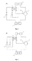
- Fig.1 discloses the upstream solution.
- a compressor 1 discharges high temperature and high pressure gas into a condenser 2, then the refrigerant flow is divided into two parts: one part (the main refrigerant flow) enters an economizer heat exchanger 5 directly, and the other part (the economizer flow) passes through an economizer expansion valve 6 then enters the economizer heat exchanger 5 as vapor/liquid mixture at an intermediate pressure.
- the main refrigerant flow from the condenser 2 is subcooled by the economizer flow before passing through a main expansion valve 3 and entering the evaporator 4, and the economizer flow is superheated in the economizer heat exchanger 5 and injected through a vapor injection line 501 to an intermediate-pressure point of the compressor 1 after leaving the economizer heat exchanger 5, thereby achieving a higher mass flow in the compressor 1 and thus a higher heating capacity.
- the injected vapor is at an intermediate pressure, it requires less energy to compress it to a pressure discharging to the condenser than if it has been injected at an evaporator pressure for suction of the compressor. This results in a reduction of specific work in the compressor which in turn results in improved system efficiency.
- Fig. 2 discloses the downstream solution.
- the compressor 1 discharges the refrigerant flow into the condenser 2, then the refrigerant flow passes through the economizer heat exchanger 5 where it will be subcooled.
- the refrigerant flow is divided into two parts: one part (the main refrigerant flow) passes through the main expansion valve 3 and then continues the refrigerant cycle through the evaporator 4 and compressor suction; the other part (the economizer flow) is evaporated with the heat form the main refrigerant flow and then enters the compressor via the vapor injection line 501.
- a valve 66 is a thermostatic expansion valve, and a temperature sensing bulb 76 is placed at the compressor injection inlet port to monitor the temperature change of the economizer heat exchanger 5.
- the change in the working conditions causes the valve 66 to open or close, thereby adjusting the amount of the economizer flow to be injected into the compressor 1.
- Fig. 9 shows an alternative case wherein a valve 67 is an electronic expansion valve.
- the electronic expansion valve 67 works the same with the thermostatic expansion valve 66, except that the conditions at the compressor injection inlet port are detected in electronic form by a temperature sensor 77 and a pressure sensor 86.
- Figs. 10 and 11 show the temperature distribution of the main refrigerant flow and the economizer flow inside and along the economizer heat exchanger 5 when the economizer expansion valve is closed and widely open, respectively.
- Fig. 10 when the valve is closed, no economizer flow (shown in broken line) is produced and no heat exchange exists in the economizer heat exchanger 5, therefore, the temperature at refrigerant flow inlet T1 equals to the temperature at refrigerant flow outlet T3, and the temperature at economizer flow inlet T2 equals to the temperature at economizer flow outlet T4. Since there is no economizer flow now, the temperatures at economizer flow inlet and outlet T2, T4 depend on the conditions. Refer to Fig.
- a heat pump system including a compressor for compressing a refrigerant, a condenser downstream of the compressor for cooling the refrigerant, a main expansion valve downstream of the condenser for lowering the pressure of the refrigerant, an evaporator downstream of the main expansion valve for vaporizing the refrigerant, an economizer heat exchanger for allowing a refrigerant flow downstream of the condenser and an economizer flow tapped upstream or downstream of the economizer heat exchanger itself to transfer heat therein, and an economizer expansion valve for controlling the amount of economizer flow entering the economizer heat exchanger through the economizer flow inlet.
- the economizer heat exchanger has a refrigerant flow inlet and a refrigerant flow outlet, and an economizer flow inlet and an economizer flow outlet. Wherein, opening of the economizer expansion valve is adjusted according to the temperature at the refrigerant flow outlet T3 and/or the temperature at the economizer flow inlet T2. In this way, the control of the economizer expansion valve and thus the amount of injected vapor is smooth and stable.
- the temperature at the refrigerant flow outlet T3 and the temperature at the economizer flow inlet T2 are both detected by temperature sensors.
- the temperature at the refrigerant flow outlet T3 is detected by a temperature sensor, and the temperature at the economizer flow inlet T2 is detected by a pressure sensor and converted via a function to temperature.
- the pressure sensor detects a pressure at the economizer flow inlet.
- the pressure sensor detects a pressure at the economizer flow outlet since it substantially equals to a pressure at the economizer flow inlet.
- the economizer expansion valve can be an electronic expansion valve.
- the economizer expansion valve can also be a thermostatic expansion valve, and in this case, the opening of the economizer expansion valve is adjusted according to the temperature at the refrigerant flow outlet T3.
- the temperature T3 is detected by a temperature sensing bulb, and the thermostatic expansion valve automatically controls its opening according to the detected temperature T3.
- Heat pumps can be used for heating purpose, like supplying hot sanitary water, or heating building interiors.
- a heat pump system typically includes a compressor 1, a condenser 2, a main expansion valve 3, and an evaporator 4. These components are generally serially connected via conduits or piping.
- the compressor 1 generally uses electrical power to compress a refrigerant form a low pressure gas state to a high pressure gas state thereby increasing the temperature, enthalpy and pressure of the refrigerant.
- the condenser 2 is typically in form of a heat exchanger well known in the state of art. The gas refrigerant leaves from the compressor 1 and then flows through the condenser 2 for being condensed at a substantially constant pressure to a saturated liquid state.
- the main expansion valve 3 is used to control the amount of refrigerant entering into the evaporator 4.
- the liquid refrigerant from the condenser 2 flows through the main expansion valve, result in the pressure of the liquid is decreased.
- the refrigerant evaporates partially causing the refrigerant to change to a mixed liquid-gas state, reducing its temperature down to a value that makes possible heat exchanges in the evaporator.
- the evaporator 4 is a heat exchanger where the heat energy available in a secondary flow, such as an external air flow, passes through it and transfers to the refrigerant flow that evaporates inside from liquid to gas.
- Heat pumps can further include components in the refrigerant circuit for inversion of the refrigerant cycle, thus, heat pumps can also be used for cooling building interiors.
- the heat pump system is provided with an economizer circuit including an economizer heat exchanger 5 and an economizer expansion valve 6.
- the economizer heat exchanger 5 includes a refrigerant flow inlet and a refrigerant flow outlet for allowing a main refrigerant flow to pass therethrough, and an economizer flow inlet and an economizer flow for allowing an economizer flow to pass therethrough.
- the economizer flow is a secondary refrigerant flow tapped upstream of the economizer heat exchanger (as shown in Fig. 1 ) or downstream of the economizer heat exchanger (as shown in Fig. 2 ), which passes through the economizer expansion valve 5 via the economizer flow inlet and outlet sequentially.
- the economizer flow is superheated by the main refrigerant flow, and injected through a vapor injection line 501 to an intermediate-pressure point of the compressor 1. In this way, the compressor achieves a higher mass flow and thus
- the economizer expansion valve 6 is used to control the amount of economizer flow entering the economizer heat exchanger 5, and accordingly the amount of gas injected into the compressor 1.
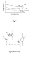
- Fig. 7 As the economizer expansion valve 6 opens step by step, the temperature at refrigerant flow outlet T3 decreases and the temperature at economizer flow inlet T2 increases.
- the variation of each of T2 and T3 is regular and stable, so it's possible to predict how far the superheating is away from the target, and then adjust the opening of the economizer expansion valve 6 to a desired size.
- the curve 93 represents the variation of the temperature difference T3-T2 along opening of the valve, which is regular and stable as well.
- control of the opening of the economizer expansion valve 6 is based on the temperature difference T3-T2 because this temperature difference can remove the influence of working conditions.
- the curve 91/92 representing the temperature variation of T2/T3 is different in different working conditions, however, the curve 93 representing the variation of temperature difference T3-T2 is almost the same in every working condition.
- Fig. 3 shows a first embodiment of the economizer circuit provided in the heat pump system aforementioned.
- the economizer circuit includes an economizer expansion valve 61, a first temperature sensor 71, and a second temperature sensor 72.
- the economizer expansion valve is an electronic expansion valve.
- the first temperature sensor 71 can be placed at the economizer flow inlet to detect the temperature T2 thereof, and the second temperature sensor 72 can be placed at the refrigerant flow outlet to detect the temperature T3 thereof.
- the signals representing temperatures T2 and T3 can feed to a controller (not shown) of the system, then the controller can calculate the temperature difference between T2 and T3, and adjust the opening size of the economizer expansion valve 61 according to the relationship as shown by the curve 93 in the Fig. 7 .
- Fig. 4 shows an alternative embodiment of the economizer circuit. Since the economizer flow passing through the economizer flow inlet and outlet is saturated vapor and the temperature T2 is the evaporation temperature, the temperature T2 can also be detected by a pressure sensor and then converted via a function to temperature. In other words, the first temperature sensor 71 in the first embodiment can be replaced by a pressure sensor 81 in present embodiment, and the detected pressure can be converted to a corresponding temperature T2.
- the pressure sensor 81 can be placed at the economizer flow outlet to detect a pressure thereof which is substantially equals to the pressure at the economizer flow inlet.
- the controller receives the signal representing the pressure value and converts it to a corresponding temperature at the economizer flow inlet T2.
- Fig. 6 shows a further embodiment of an economizer circuit employing a thermostatic expansion valve 62.
- the valve 62 has a temperature sensing bulb 73 placed at the refrigerant flow outlet to sense the temperature T3 thereof. It would be apparent to those skilled in the art that, the bulb 73 can cause the valve to open against the spring pressure in the valve body as the temperature on the bulb increases, and cause the valve to close when the temperature decreases. Therefore, the economizer expansion valve 62 automatically controls its opening according to the detected temperature T3.
- the economizer expansion valve can be adjusted only based on the temperature at the economizer flow inlet T2.
- the economizer expansion valve can be an electronic expansion valve, and a temperature sensor is placed at the economizer inlet to detect the temperature T2.
- the controller receives the signal representing temperature T2, and controls the opening of the economizer expansion valve according to the relationship as shown by the curve 92 of the Fig. 7 in a specific working condition.
Landscapes
- Engineering & Computer Science (AREA)
- Physics & Mathematics (AREA)
- Mechanical Engineering (AREA)
- Thermal Sciences (AREA)
- General Engineering & Computer Science (AREA)
- Air Conditioning Control Device (AREA)
Abstract
The present invention discloses a heat pump system including a compressor for compressing a refrigerant, a condenser downstream of the compressor for cooling the refrigerant, a main expansion valve downstream of the condenser for lowering the pressure of the refrigerant, an evaporator downstream of the main expansion valve for vaporizing the refrigerant, an economizer heat exchanger for allowing a refrigerant flow downstream of the condenser and an economizer flow tapped upstream or downstream of the economizer heat exchanger itself to transfer heat therein, and an economizer expansion valve for controlling the amount of economizer flow entering the economizer heat exchanger through the economizer flow inlet. The economizer heat exchanger has a refrigerant flow inlet and a refrigerant flow outlet, and an economizer flow inlet and an economizer flow outlet. Wherein, opening of the economizer expansion valve is adjusted according to the temperature at the refrigerant flow outlet T3 and/or the temperature at the economizer flow inlet T2. In this way, the control of the economizer expansion valve and thus the amount of injected vapor is smooth and stable.
Description
- The present invention relates to a heat pump system wherein an economizer heat exchanger is used as an evaporator for the vapor injection into a compressor.
- A basic heat pump system typically has a compressor, a condenser, an expansion device, and an evaporator. These components are generally serially connected via conduits or piping and are well known in the art. It would be desirable to achieve increased capacity or increased efficiency operation for the heat pump system. One way of achieving increased capacity or increased efficiency operation is the inclusion of an economizer circuit into the heat pump system. An economizer circuit essentially provides heat transfer between a main refrigerant flow downstream of the condenser and a second refrigerant flow (namely an economizer flow) in an economizer heat exchanger. Under certain operational conditions, the second refrigerant flow is tapped upstream or downstream of the economizer heat exchanger.
-
Fig.1 discloses the upstream solution. Acompressor 1 discharges high temperature and high pressure gas into acondenser 2, then the refrigerant flow is divided into two parts: one part (the main refrigerant flow) enters aneconomizer heat exchanger 5 directly, and the other part (the economizer flow) passes through an economizer expansion valve 6 then enters theeconomizer heat exchanger 5 as vapor/liquid mixture at an intermediate pressure. In this way, the main refrigerant flow from thecondenser 2 is subcooled by the economizer flow before passing through amain expansion valve 3 and entering theevaporator 4, and the economizer flow is superheated in theeconomizer heat exchanger 5 and injected through avapor injection line 501 to an intermediate-pressure point of thecompressor 1 after leaving theeconomizer heat exchanger 5, thereby achieving a higher mass flow in thecompressor 1 and thus a higher heating capacity. Since the injected vapor is at an intermediate pressure, it requires less energy to compress it to a pressure discharging to the condenser than if it has been injected at an evaporator pressure for suction of the compressor. This results in a reduction of specific work in the compressor which in turn results in improved system efficiency. -
Fig. 2 discloses the downstream solution. In this case, thecompressor 1 discharges the refrigerant flow into thecondenser 2, then the refrigerant flow passes through theeconomizer heat exchanger 5 where it will be subcooled. After that, the refrigerant flow is divided into two parts: one part (the main refrigerant flow) passes through themain expansion valve 3 and then continues the refrigerant cycle through theevaporator 4 and compressor suction; the other part (the economizer flow) is evaporated with the heat form the main refrigerant flow and then enters the compressor via thevapor injection line 501. - In any of the two solutions, the superheating control can be achieved according to the temperature at the compressor injection inlet port. As an economizer circuit shown in
Fig. 8 , avalve 66 is a thermostatic expansion valve, and atemperature sensing bulb 76 is placed at the compressor injection inlet port to monitor the temperature change of theeconomizer heat exchanger 5. The change in the working conditions causes thevalve 66 to open or close, thereby adjusting the amount of the economizer flow to be injected into thecompressor 1.Fig. 9 shows an alternative case wherein avalve 67 is an electronic expansion valve. Theelectronic expansion valve 67 works the same with thethermostatic expansion valve 66, except that the conditions at the compressor injection inlet port are detected in electronic form by atemperature sensor 77 and apressure sensor 86. -
Figs. 10 and 11 show the temperature distribution of the main refrigerant flow and the economizer flow inside and along theeconomizer heat exchanger 5 when the economizer expansion valve is closed and widely open, respectively. Refer toFig. 10 , when the valve is closed, no economizer flow (shown in broken line) is produced and no heat exchange exists in theeconomizer heat exchanger 5, therefore, the temperature at refrigerant flow inlet T1 equals to the temperature at refrigerant flow outlet T3, and the temperature at economizer flow inlet T2 equals to the temperature at economizer flow outlet T4. Since there is no economizer flow now, the temperatures at economizer flow inlet and outlet T2, T4 depend on the conditions. Refer toFig. 11 , when the economizer expansion valve is widely open, the main refrigerant flow is subcooled, which result in the temperature at refrigerant flow outlet T3 decreases and tends to the temperature at economizer flow inlet T2, and the economizer flow is superheated and therefore the temperature at economizer flow outlet T4 increases. However, as the opening of the economizer expansion valve is adjusted step by step, the temperature at compressor injection inlet port, namely T4, does not increase regularly or proportionally, in fact, change of T4 is almost nothing in a long period after starting opening the economizer expansion valve, and the T4 goes up sharply when it is getting to the superheating target. Obviously, this is difficult to predict where the superheating starts and ends, it is also difficult to control the economizer expansion valve and thus the amount of injected vapor into the compressor in a stable and reliable way, especially in the case to reach a small superheating target. - It is an object of present invention to provide a heat pump system wherein the amount of injected vapor is controlled in a reliable and stable way.
- According to one aspect of the present invention there is provided a heat pump system including a compressor for compressing a refrigerant, a condenser downstream of the compressor for cooling the refrigerant, a main expansion valve downstream of the condenser for lowering the pressure of the refrigerant, an evaporator downstream of the main expansion valve for vaporizing the refrigerant, an economizer heat exchanger for allowing a refrigerant flow downstream of the condenser and an economizer flow tapped upstream or downstream of the economizer heat exchanger itself to transfer heat therein, and an economizer expansion valve for controlling the amount of economizer flow entering the economizer heat exchanger through the economizer flow inlet. The economizer heat exchanger has a refrigerant flow inlet and a refrigerant flow outlet, and an economizer flow inlet and an economizer flow outlet. Wherein, opening of the economizer expansion valve is adjusted according to the temperature at the refrigerant flow outlet T3 and/or the temperature at the economizer flow inlet T2. In this way, the control of the economizer expansion valve and thus the amount of injected vapor is smooth and stable.
- When the opening is adjusted according to the temperatures T3 and T2, it will be appreciated to use the temperature difference T3-T2 because using temperature difference can remove the influence of working conditions.
- In one embodiment, the temperature at the refrigerant flow outlet T3 and the temperature at the economizer flow inlet T2 are both detected by temperature sensors.
- In an alternative embodiment, the temperature at the refrigerant flow outlet T3 is detected by a temperature sensor, and the temperature at the economizer flow inlet T2 is detected by a pressure sensor and converted via a function to temperature.
- Preferably, the pressure sensor detects a pressure at the economizer flow inlet.
- Alternatively, the pressure sensor detects a pressure at the economizer flow outlet since it substantially equals to a pressure at the economizer flow inlet.
- The economizer expansion valve can be an electronic expansion valve.
- The economizer expansion valve can also be a thermostatic expansion valve, and in this case, the opening of the economizer expansion valve is adjusted according to the temperature at the refrigerant flow outlet T3. The temperature T3 is detected by a temperature sensing bulb, and the thermostatic expansion valve automatically controls its opening according to the detected temperature T3.
- For a more complete understanding of the present invention, and the advantages thereof, reference is now made to the following descriptions taken in conjunction with the accompanying drawings, in which:
-
Fig. 1 shows one example of a heat pump system including an economizer circuit for vapor injection application; -
Fig. 2 shows another example of a heat pump system including an economizer circuit for vapor injection application; -
Fig. 3 is a schematic view showing a first embodiment of the economizer circuit included in the heat pump system as shown inFig. 1 or 2 ; -
Fig. 4 is a schematic view showing a second embodiment of the economizer circuit included in the heat pump system as shown inFig. 1 or 2 ; -
Fig. 5 is a schematic view showing a third embodiment of the economizer circuit included in the heat pump system as shown inFig. 1 or 2 ; -
Fig. 6 is a schematic view showing a fourth embodiment of the economizer circuit included in the heat pump system as shown inFig. 1 or 2 ; -
Fig. 7 is a diagram schematically showing variations of a temperature at refrigerant flow outlet, a temperature at economizer flow inlet, and the difference between these two temperatures along opening of an economizer expansion valve; -
Fig. 8 is a schematic view showing an economizer circuit in the state of art, wherein the economizer circuit includes a thermostatic expansion valve; -
Fig. 9 is a schematic view showing another economizer circuit in the state of art, wherein the economizer circuit includes an electronic expansion valve; -
Fig. 10 shows temperature distribution of an refrigerant flow passing through an economizer heat exchanger of the economizer circuit as shown inFig. 9 or 10 , wherein the expansion valve is closed; -
Fig. 11 shows temperature distributions of an refrigerant flow and an economizer flow passing through an economizer heat exchanger of the economizer circuit as shown inFig. 9 or 10 , wherein the expansion valve is widely open. - Reference will now be made to the drawing figures to describe the preferred embodiments of the present invention in detail. However, the embodiments can not be used to restrict the present invention. Changes such as structure, method and function obviously made to those of ordinary skill in the art are also protected by the present invention.
- Heat pumps can be used for heating purpose, like supplying hot sanitary water, or heating building interiors. Refer to
Figs. 1 and 2 , a heat pump system typically includes acompressor 1, acondenser 2, amain expansion valve 3, and anevaporator 4. These components are generally serially connected via conduits or piping. Thecompressor 1 generally uses electrical power to compress a refrigerant form a low pressure gas state to a high pressure gas state thereby increasing the temperature, enthalpy and pressure of the refrigerant. Thecondenser 2 is typically in form of a heat exchanger well known in the state of art. The gas refrigerant leaves from thecompressor 1 and then flows through thecondenser 2 for being condensed at a substantially constant pressure to a saturated liquid state. Themain expansion valve 3 is used to control the amount of refrigerant entering into theevaporator 4. The liquid refrigerant from thecondenser 2 flows through the main expansion valve, result in the pressure of the liquid is decreased. In the process, the refrigerant evaporates partially causing the refrigerant to change to a mixed liquid-gas state, reducing its temperature down to a value that makes possible heat exchanges in the evaporator. Theevaporator 4 is a heat exchanger where the heat energy available in a secondary flow, such as an external air flow, passes through it and transfers to the refrigerant flow that evaporates inside from liquid to gas. Heat pumps can further include components in the refrigerant circuit for inversion of the refrigerant cycle, thus, heat pumps can also be used for cooling building interiors. - The heat pump system is provided with an economizer circuit including an
economizer heat exchanger 5 and an economizer expansion valve 6. Theeconomizer heat exchanger 5 includes a refrigerant flow inlet and a refrigerant flow outlet for allowing a main refrigerant flow to pass therethrough, and an economizer flow inlet and an economizer flow for allowing an economizer flow to pass therethrough. The economizer flow is a secondary refrigerant flow tapped upstream of the economizer heat exchanger (as shown inFig. 1 ) or downstream of the economizer heat exchanger (as shown inFig. 2 ), which passes through theeconomizer expansion valve 5 via the economizer flow inlet and outlet sequentially. The economizer flow is superheated by the main refrigerant flow, and injected through avapor injection line 501 to an intermediate-pressure point of thecompressor 1. In this way, the compressor achieves a higher mass flow and thus has a higher heating capacity. - The economizer expansion valve 6 is used to control the amount of economizer flow entering the
economizer heat exchanger 5, and accordingly the amount of gas injected into thecompressor 1. With reference toFig. 7 , as the economizer expansion valve 6 opens step by step, the temperature at refrigerant flow outlet T3 decreases and the temperature at economizer flow inlet T2 increases. As shown by thecurves curve 93 represents the variation of the temperature difference T3-T2 along opening of the valve, which is regular and stable as well. Since T2 and T3 both depend on working conditions, it would be complicated to control because a corresponding working condition has to be considered. Accordingly, in a preferred embodiment, control of the opening of the economizer expansion valve 6 is based on the temperature difference T3-T2 because this temperature difference can remove the influence of working conditions. In other words, thecurve 91/92 representing the temperature variation of T2/T3 is different in different working conditions, however, thecurve 93 representing the variation of temperature difference T3-T2 is almost the same in every working condition. -
Fig. 3 shows a first embodiment of the economizer circuit provided in the heat pump system aforementioned. The economizer circuit includes aneconomizer expansion valve 61, a first temperature sensor 71, and asecond temperature sensor 72. In this embodiment, the economizer expansion valve is an electronic expansion valve. The first temperature sensor 71 can be placed at the economizer flow inlet to detect the temperature T2 thereof, and thesecond temperature sensor 72 can be placed at the refrigerant flow outlet to detect the temperature T3 thereof. The signals representing temperatures T2 and T3 can feed to a controller (not shown) of the system, then the controller can calculate the temperature difference between T2 and T3, and adjust the opening size of theeconomizer expansion valve 61 according to the relationship as shown by thecurve 93 in theFig. 7 . -
Fig. 4 shows an alternative embodiment of the economizer circuit. Since the economizer flow passing through the economizer flow inlet and outlet is saturated vapor and the temperature T2 is the evaporation temperature, the temperature T2 can also be detected by a pressure sensor and then converted via a function to temperature. In other words, the first temperature sensor 71 in the first embodiment can be replaced by apressure sensor 81 in present embodiment, and the detected pressure can be converted to a corresponding temperature T2. Refer toFig. 5 , as the economizer flow passes through the economizer flow inlet and outlet at a substantially constant pressure, thepressure sensor 81 can be placed at the economizer flow outlet to detect a pressure thereof which is substantially equals to the pressure at the economizer flow inlet. The controller receives the signal representing the pressure value and converts it to a corresponding temperature at the economizer flow inlet T2. -
Fig. 6 shows a further embodiment of an economizer circuit employing athermostatic expansion valve 62. Thevalve 62 has atemperature sensing bulb 73 placed at the refrigerant flow outlet to sense the temperature T3 thereof. It would be apparent to those skilled in the art that, thebulb 73 can cause the valve to open against the spring pressure in the valve body as the temperature on the bulb increases, and cause the valve to close when the temperature decreases. Therefore, theeconomizer expansion valve 62 automatically controls its opening according to the detected temperature T3. Those skilled in the art will also understand that the economizer expansion valve can be adjusted only based on the temperature at the economizer flow inlet T2. For example, the economizer expansion valve can be an electronic expansion valve, and a temperature sensor is placed at the economizer inlet to detect the temperature T2. The controller receives the signal representing temperature T2, and controls the opening of the economizer expansion valve according to the relationship as shown by thecurve 92 of theFig. 7 in a specific working condition. - It is to be understood, however, that even though numerous, characteristics and advantages of the present invention have been set forth in the foregoing description, together with details of the structure and function of the invention, the disclosed is illustrative only, and changes may be made in detail, especially in matters of number, shape, size, and arrangement of parts within the principles of the invention to the full extent indicated by the broadest general meaning of the terms in which the appended claims are expressed.
Claims (9)
- A heat pump system comprising:a compressor for compressing a refrigerant, a condenser downstream of the compressor for cooling the refrigerant, a main expansion valve downstream of the condenser for lowering the pressure of the refrigerant, an evaporator downstream of the main expansion valve for vaporizing the refrigerant;an economizer heat exchanger for allowing a refrigerant flow downstream of the condenser and an economizer flow tapped upstream or downstream of the economizer heat exchanger itself to transfer heat therein, said economizer heat exchanger having a refrigerant flow inlet and a refrigerant flow outlet, and an economizer flow inlet and an economizer flow outlet;an economizer expansion valve for controlling the amount of economizer flow entering the economizer heat exchanger through the economizer flow inlet, whereinopening of the economizer expansion valve is adjusted according to the temperature at the refrigerant flow outlet (T3) and/or the temperature at the economizer flow inlet (T2).
- A heat pump system according to claim 1, wherein the opening of the economizer expansion valve is adjusted according to the temperature difference at the refrigerant flow outlet and at the economizer flow inlet (T3-T2).
- A heat pump system according to claim 2, wherein the temperature at the refrigerant flow outlet (T3) and the temperature at the economizer flow inlet (T2) are both detected by temperature sensors.
- A heat pump system according to claim 2, wherein the temperature at the refrigerant flow outlet (T3) is detected by a temperature sensor, and the temperature at the economizer flow inlet (T2) is detected by a pressure sensor and converted via a function to temperature.
- A heat pump system according to claim 4, wherein the pressure sensor detects a pressure at the economizer flow inlet.
- A heat pump system according to claim 4, wherein the pressure sensor detects a pressure at the economizer flow outlet substantially equals to a pressure at the economizer flow inlet.
- A heat pump system according to claim 2, wherein the economizer expansion valve is an electronic expansion valve.
- A heat pump system according to claim 2, wherein the economizer expansion valve is a thermostatic expansion valve, and the opening of the economizer expansion valve is adjusted according to the temperature at the refrigerant flow outlet (T3).
- A heat pump system according to claim 8, wherein said thermostatic expansion valve comprises a temperature sensing bulb placed at the refrigerant flow outlet to detect the temperature thereof (T3), and said thermostatic expansion valve automatically controls its opening according to said detected temperature (T3).
Priority Applications (2)
| Application Number | Priority Date | Filing Date | Title |
|---|---|---|---|
| EP14194026.2A EP3023711A1 (en) | 2014-11-20 | 2014-11-20 | Energy control for vapour injection |
| CN201510799663.9A CN105627629A (en) | 2014-11-20 | 2015-11-19 | Heat pump system using economizer loop t inject steam into compressor |
Applications Claiming Priority (1)
| Application Number | Priority Date | Filing Date | Title |
|---|---|---|---|
| EP14194026.2A EP3023711A1 (en) | 2014-11-20 | 2014-11-20 | Energy control for vapour injection |
Publications (1)
| Publication Number | Publication Date |
|---|---|
| EP3023711A1 true EP3023711A1 (en) | 2016-05-25 |
Family
ID=52102381
Family Applications (1)
| Application Number | Title | Priority Date | Filing Date |
|---|---|---|---|
| EP14194026.2A Withdrawn EP3023711A1 (en) | 2014-11-20 | 2014-11-20 | Energy control for vapour injection |
Country Status (2)
| Country | Link |
|---|---|
| EP (1) | EP3023711A1 (en) |
| CN (1) | CN105627629A (en) |
Cited By (6)
| Publication number | Priority date | Publication date | Assignee | Title |
|---|---|---|---|---|
| WO2018011841A1 (en) * | 2016-07-11 | 2018-01-18 | 三菱電機株式会社 | Refrigerating and air-conditioning apparatus |
| CN109028640A (en) * | 2018-07-03 | 2018-12-18 | 浙江国祥股份有限公司 | A kind of air source heat pump and its flow control technique |
| CN111981648A (en) * | 2020-08-25 | 2020-11-24 | Tcl空调器(中山)有限公司 | Heating control method and device for air conditioner, air conditioner and readable storage medium |
| CN116857851A (en) * | 2023-07-31 | 2023-10-10 | 浙江智马达智能科技有限公司 | Control method for refrigerant loop series valve of heat pump system and heat pump system |
| CN119468541A (en) * | 2024-11-21 | 2025-02-18 | 广东芬尼能源技术有限公司 | Heat pump unit, heat pump unit operation control method, device and storage medium |
| EP4575355A1 (en) | 2023-12-06 | 2025-06-25 | Panasonic Intellectual Property Management Co., Ltd. | Refrigeration cycle apparatus |
Families Citing this family (2)
| Publication number | Priority date | Publication date | Assignee | Title |
|---|---|---|---|---|
| CN110285598B (en) * | 2019-06-28 | 2021-07-20 | 广东美的暖通设备有限公司 | Jet-enhanced air conditioner system, method, and jet-enthalpy air conditioner and readable storage medium |
| CN110388763A (en) * | 2019-07-29 | 2019-10-29 | 广东美的暖通设备有限公司 | Air conditioner and water heater |
Citations (2)
| Publication number | Priority date | Publication date | Assignee | Title |
|---|---|---|---|---|
| US6474087B1 (en) * | 2001-10-03 | 2002-11-05 | Carrier Corporation | Method and apparatus for the control of economizer circuit flow for optimum performance |
| JP2010007975A (en) * | 2008-06-27 | 2010-01-14 | Daikin Ind Ltd | Economizer cycle refrigerating apparatus |
Family Cites Families (5)
| Publication number | Priority date | Publication date | Assignee | Title |
|---|---|---|---|---|
| CN1135341C (en) * | 1994-05-30 | 2004-01-21 | 三菱电机株式会社 | Refrigeration cycle system |
| EP2064496B1 (en) * | 2006-09-18 | 2018-04-25 | Carrier Corporation | Refrigerant system with expansion device bypass |
| CN200996753Y (en) * | 2006-12-26 | 2007-12-26 | 海信集团有限公司 | Refrigerating system of intermediate air-compensating compressor with economizer |
| JP5411643B2 (en) * | 2009-10-05 | 2014-02-12 | パナソニック株式会社 | Refrigeration cycle apparatus and hot water heater |
| JP5579243B2 (en) * | 2012-10-26 | 2014-08-27 | 三菱電機株式会社 | Refrigeration cycle equipment |
-
2014
- 2014-11-20 EP EP14194026.2A patent/EP3023711A1/en not_active Withdrawn
-
2015
- 2015-11-19 CN CN201510799663.9A patent/CN105627629A/en active Pending
Patent Citations (2)
| Publication number | Priority date | Publication date | Assignee | Title |
|---|---|---|---|---|
| US6474087B1 (en) * | 2001-10-03 | 2002-11-05 | Carrier Corporation | Method and apparatus for the control of economizer circuit flow for optimum performance |
| JP2010007975A (en) * | 2008-06-27 | 2010-01-14 | Daikin Ind Ltd | Economizer cycle refrigerating apparatus |
Cited By (6)
| Publication number | Priority date | Publication date | Assignee | Title |
|---|---|---|---|---|
| WO2018011841A1 (en) * | 2016-07-11 | 2018-01-18 | 三菱電機株式会社 | Refrigerating and air-conditioning apparatus |
| CN109028640A (en) * | 2018-07-03 | 2018-12-18 | 浙江国祥股份有限公司 | A kind of air source heat pump and its flow control technique |
| CN111981648A (en) * | 2020-08-25 | 2020-11-24 | Tcl空调器(中山)有限公司 | Heating control method and device for air conditioner, air conditioner and readable storage medium |
| CN116857851A (en) * | 2023-07-31 | 2023-10-10 | 浙江智马达智能科技有限公司 | Control method for refrigerant loop series valve of heat pump system and heat pump system |
| EP4575355A1 (en) | 2023-12-06 | 2025-06-25 | Panasonic Intellectual Property Management Co., Ltd. | Refrigeration cycle apparatus |
| CN119468541A (en) * | 2024-11-21 | 2025-02-18 | 广东芬尼能源技术有限公司 | Heat pump unit, heat pump unit operation control method, device and storage medium |
Also Published As
| Publication number | Publication date |
|---|---|
| CN105627629A (en) | 2016-06-01 |
Similar Documents
| Publication | Publication Date | Title |
|---|---|---|
| CN104697234B (en) | Refrigerant-cycle systems and its control method | |
| EP3246637A1 (en) | Refrigeration cycle device | |
| JP2015078800A5 (en) | ||
| CN109140826A (en) | Enthalpy-increasing heat pump, air compensation amount control method and system thereof, computer equipment and storage medium | |
| CN104807229A (en) | Multi-split air conditioner and control method thereof | |
| WO2005059446A3 (en) | Loss of refrigerant charge and expansion valve malfunction detection | |
| CN103363745B (en) | Refrigerating plant and Temp. control method thereof | |
| CN102645026B (en) | Control method for electronic expansion valve of heat pump water heater | |
| CN104634033A (en) | Electronic expansion valve control system and method | |
| US9714581B2 (en) | Rankine cycle apparatus | |
| US20230258377A1 (en) | Refrigeration system and the control method thereof | |
| CN107990609A (en) | Control method of electronic expansion valve and refrigerant circulating system | |
| EP3140025B1 (en) | Method and device for cool-drying a gas with circulating cooling liquid with bypass line | |
| JP2014214913A (en) | Oil return controller and refrigerator | |
| CN105627629A (en) | Heat pump system using economizer loop t inject steam into compressor | |
| CN107449191A (en) | Air-conditioning system and its heat-production control method, device and machinable medium | |
| RU2016151260A (en) | EVAPORATOR LIQUID HEATER TO REDUCE THE REFRIGERANT CHARGE | |
| CN111907301A (en) | Combined heat exchanger, heat exchange system and optimization method thereof | |
| JP6250428B2 (en) | Refrigeration cycle equipment | |
| CN101122436A (en) | Constant speed hot pump unit with logic control throttle style and its control method | |
| JP6119895B1 (en) | Heat pump equipment | |
| US9702263B2 (en) | Rankine cycle device | |
| EP3140026B1 (en) | Method for cool drying a gas | |
| WO2020065999A1 (en) | Outdoor unit for refrigeration cycle device, refrigeration cycle device, and air conditioning device | |
| CN105650919B (en) | Air conditioning system and air injection superheat degree adjusting method |
Legal Events
| Date | Code | Title | Description |
|---|---|---|---|
| AK | Designated contracting states |
Kind code of ref document: A1 Designated state(s): AL AT BE BG CH CY CZ DE DK EE ES FI FR GB GR HR HU IE IS IT LI LT LU LV MC MK MT NL NO PL PT RO RS SE SI SK SM TR |
|
| AX | Request for extension of the european patent |
Extension state: BA ME |
|
| PUAI | Public reference made under article 153(3) epc to a published international application that has entered the european phase |
Free format text: ORIGINAL CODE: 0009012 |
|
| STAA | Information on the status of an ep patent application or granted ep patent |
Free format text: STATUS: THE APPLICATION IS DEEMED TO BE WITHDRAWN |
|
| 18D | Application deemed to be withdrawn |
Effective date: 20161126 |