EP3023662A1 - Reduced noise flexplate - Google Patents
Reduced noise flexplate Download PDFInfo
- Publication number
- EP3023662A1 EP3023662A1 EP15182006.5A EP15182006A EP3023662A1 EP 3023662 A1 EP3023662 A1 EP 3023662A1 EP 15182006 A EP15182006 A EP 15182006A EP 3023662 A1 EP3023662 A1 EP 3023662A1
- Authority
- EP
- European Patent Office
- Prior art keywords
- plate
- noise
- central plate
- ring gear
- central
- Prior art date
- Legal status (The legal status is an assumption and is not a legal conclusion. Google has not performed a legal analysis and makes no representation as to the accuracy of the status listed.)
- Granted
Links
Images








Classifications
-
- F—MECHANICAL ENGINEERING; LIGHTING; HEATING; WEAPONS; BLASTING
- F16—ENGINEERING ELEMENTS AND UNITS; GENERAL MEASURES FOR PRODUCING AND MAINTAINING EFFECTIVE FUNCTIONING OF MACHINES OR INSTALLATIONS; THERMAL INSULATION IN GENERAL
- F16F—SPRINGS; SHOCK-ABSORBERS; MEANS FOR DAMPING VIBRATION
- F16F15/00—Suppression of vibrations in systems; Means or arrangements for avoiding or reducing out-of-balance forces, e.g. due to motion
- F16F15/10—Suppression of vibrations in rotating systems by making use of members moving with the system
- F16F15/12—Suppression of vibrations in rotating systems by making use of members moving with the system using elastic members or friction-damping members, e.g. between a rotating shaft and a gyratory mass mounted thereon
- F16F15/129—Suppression of vibrations in rotating systems by making use of members moving with the system using elastic members or friction-damping members, e.g. between a rotating shaft and a gyratory mass mounted thereon characterised by friction-damping means
-
- B—PERFORMING OPERATIONS; TRANSPORTING
- B60—VEHICLES IN GENERAL
- B60K—ARRANGEMENT OR MOUNTING OF PROPULSION UNITS OR OF TRANSMISSIONS IN VEHICLES; ARRANGEMENT OR MOUNTING OF PLURAL DIVERSE PRIME-MOVERS IN VEHICLES; AUXILIARY DRIVES FOR VEHICLES; INSTRUMENTATION OR DASHBOARDS FOR VEHICLES; ARRANGEMENTS IN CONNECTION WITH COOLING, AIR INTAKE, GAS EXHAUST OR FUEL SUPPLY OF PROPULSION UNITS IN VEHICLES
- B60K17/00—Arrangement or mounting of transmissions in vehicles
-
- F—MECHANICAL ENGINEERING; LIGHTING; HEATING; WEAPONS; BLASTING
- F02—COMBUSTION ENGINES; HOT-GAS OR COMBUSTION-PRODUCT ENGINE PLANTS
- F02N—STARTING OF COMBUSTION ENGINES; STARTING AIDS FOR SUCH ENGINES, NOT OTHERWISE PROVIDED FOR
- F02N15/00—Other power-operated starting apparatus; Component parts, details, or accessories, not provided for in, or of interest apart from groups F02N5/00 - F02N13/00
- F02N15/02—Gearing between starting-engines and started engines; Engagement or disengagement thereof
-
- F—MECHANICAL ENGINEERING; LIGHTING; HEATING; WEAPONS; BLASTING
- F16—ENGINEERING ELEMENTS AND UNITS; GENERAL MEASURES FOR PRODUCING AND MAINTAINING EFFECTIVE FUNCTIONING OF MACHINES OR INSTALLATIONS; THERMAL INSULATION IN GENERAL
- F16D—COUPLINGS FOR TRANSMITTING ROTATION; CLUTCHES; BRAKES
- F16D1/00—Couplings for rigidly connecting two coaxial shafts or other movable machine elements
-
- F—MECHANICAL ENGINEERING; LIGHTING; HEATING; WEAPONS; BLASTING
- F16—ENGINEERING ELEMENTS AND UNITS; GENERAL MEASURES FOR PRODUCING AND MAINTAINING EFFECTIVE FUNCTIONING OF MACHINES OR INSTALLATIONS; THERMAL INSULATION IN GENERAL
- F16D—COUPLINGS FOR TRANSMITTING ROTATION; CLUTCHES; BRAKES
- F16D3/00—Yielding couplings, i.e. with means permitting movement between the connected parts during the drive
- F16D3/02—Yielding couplings, i.e. with means permitting movement between the connected parts during the drive adapted to specific functions
- F16D3/14—Yielding couplings, i.e. with means permitting movement between the connected parts during the drive adapted to specific functions combined with a friction coupling for damping vibration or absorbing shock
-
- F—MECHANICAL ENGINEERING; LIGHTING; HEATING; WEAPONS; BLASTING
- F16—ENGINEERING ELEMENTS AND UNITS; GENERAL MEASURES FOR PRODUCING AND MAINTAINING EFFECTIVE FUNCTIONING OF MACHINES OR INSTALLATIONS; THERMAL INSULATION IN GENERAL
- F16D—COUPLINGS FOR TRANSMITTING ROTATION; CLUTCHES; BRAKES
- F16D3/00—Yielding couplings, i.e. with means permitting movement between the connected parts during the drive
- F16D3/50—Yielding couplings, i.e. with means permitting movement between the connected parts during the drive with the coupling parts connected by one or more intermediate members
- F16D3/72—Yielding couplings, i.e. with means permitting movement between the connected parts during the drive with the coupling parts connected by one or more intermediate members with axially-spaced attachments to the coupling parts
-
- F—MECHANICAL ENGINEERING; LIGHTING; HEATING; WEAPONS; BLASTING
- F16—ENGINEERING ELEMENTS AND UNITS; GENERAL MEASURES FOR PRODUCING AND MAINTAINING EFFECTIVE FUNCTIONING OF MACHINES OR INSTALLATIONS; THERMAL INSULATION IN GENERAL
- F16D—COUPLINGS FOR TRANSMITTING ROTATION; CLUTCHES; BRAKES
- F16D3/00—Yielding couplings, i.e. with means permitting movement between the connected parts during the drive
- F16D3/50—Yielding couplings, i.e. with means permitting movement between the connected parts during the drive with the coupling parts connected by one or more intermediate members
- F16D3/76—Yielding couplings, i.e. with means permitting movement between the connected parts during the drive with the coupling parts connected by one or more intermediate members shaped as an elastic ring centered on the axis, surrounding a portion of one coupling part and surrounded by a sleeve of the other coupling part
- F16D3/77—Yielding couplings, i.e. with means permitting movement between the connected parts during the drive with the coupling parts connected by one or more intermediate members shaped as an elastic ring centered on the axis, surrounding a portion of one coupling part and surrounded by a sleeve of the other coupling part the ring being metallic
-
- F—MECHANICAL ENGINEERING; LIGHTING; HEATING; WEAPONS; BLASTING
- F16—ENGINEERING ELEMENTS AND UNITS; GENERAL MEASURES FOR PRODUCING AND MAINTAINING EFFECTIVE FUNCTIONING OF MACHINES OR INSTALLATIONS; THERMAL INSULATION IN GENERAL
- F16D—COUPLINGS FOR TRANSMITTING ROTATION; CLUTCHES; BRAKES
- F16D3/00—Yielding couplings, i.e. with means permitting movement between the connected parts during the drive
- F16D3/50—Yielding couplings, i.e. with means permitting movement between the connected parts during the drive with the coupling parts connected by one or more intermediate members
- F16D3/78—Yielding couplings, i.e. with means permitting movement between the connected parts during the drive with the coupling parts connected by one or more intermediate members shaped as an elastic disc or flat ring, arranged perpendicular to the axis of the coupling parts, different sets of spots of the disc or ring being attached to each coupling part, e.g. Hardy couplings
- F16D3/79—Yielding couplings, i.e. with means permitting movement between the connected parts during the drive with the coupling parts connected by one or more intermediate members shaped as an elastic disc or flat ring, arranged perpendicular to the axis of the coupling parts, different sets of spots of the disc or ring being attached to each coupling part, e.g. Hardy couplings the disc or ring being metallic
-
- F—MECHANICAL ENGINEERING; LIGHTING; HEATING; WEAPONS; BLASTING
- F16—ENGINEERING ELEMENTS AND UNITS; GENERAL MEASURES FOR PRODUCING AND MAINTAINING EFFECTIVE FUNCTIONING OF MACHINES OR INSTALLATIONS; THERMAL INSULATION IN GENERAL
- F16D—COUPLINGS FOR TRANSMITTING ROTATION; CLUTCHES; BRAKES
- F16D65/00—Parts or details
- F16D65/0006—Noise or vibration control
-
- F—MECHANICAL ENGINEERING; LIGHTING; HEATING; WEAPONS; BLASTING
- F16—ENGINEERING ELEMENTS AND UNITS; GENERAL MEASURES FOR PRODUCING AND MAINTAINING EFFECTIVE FUNCTIONING OF MACHINES OR INSTALLATIONS; THERMAL INSULATION IN GENERAL
- F16F—SPRINGS; SHOCK-ABSORBERS; MEANS FOR DAMPING VIBRATION
- F16F15/00—Suppression of vibrations in systems; Means or arrangements for avoiding or reducing out-of-balance forces, e.g. due to motion
- F16F15/10—Suppression of vibrations in rotating systems by making use of members moving with the system
-
- F—MECHANICAL ENGINEERING; LIGHTING; HEATING; WEAPONS; BLASTING
- F16—ENGINEERING ELEMENTS AND UNITS; GENERAL MEASURES FOR PRODUCING AND MAINTAINING EFFECTIVE FUNCTIONING OF MACHINES OR INSTALLATIONS; THERMAL INSULATION IN GENERAL
- F16F—SPRINGS; SHOCK-ABSORBERS; MEANS FOR DAMPING VIBRATION
- F16F15/00—Suppression of vibrations in systems; Means or arrangements for avoiding or reducing out-of-balance forces, e.g. due to motion
- F16F15/30—Flywheels
-
- F—MECHANICAL ENGINEERING; LIGHTING; HEATING; WEAPONS; BLASTING
- F16—ENGINEERING ELEMENTS AND UNITS; GENERAL MEASURES FOR PRODUCING AND MAINTAINING EFFECTIVE FUNCTIONING OF MACHINES OR INSTALLATIONS; THERMAL INSULATION IN GENERAL
- F16H—GEARING
- F16H55/00—Elements with teeth or friction surfaces for conveying motion; Worms, pulleys or sheaves for gearing mechanisms
- F16H55/02—Toothed members; Worms
- F16H55/14—Construction providing resilience or vibration-damping
-
- F—MECHANICAL ENGINEERING; LIGHTING; HEATING; WEAPONS; BLASTING
- F02—COMBUSTION ENGINES; HOT-GAS OR COMBUSTION-PRODUCT ENGINE PLANTS
- F02N—STARTING OF COMBUSTION ENGINES; STARTING AIDS FOR SUCH ENGINES, NOT OTHERWISE PROVIDED FOR
- F02N11/00—Starting of engines by means of electric motors
- F02N11/08—Circuits specially adapted for starting of engines
- F02N11/0814—Circuits specially adapted for starting of engines comprising means for controlling automatic idle-start-stop
-
- F—MECHANICAL ENGINEERING; LIGHTING; HEATING; WEAPONS; BLASTING
- F16—ENGINEERING ELEMENTS AND UNITS; GENERAL MEASURES FOR PRODUCING AND MAINTAINING EFFECTIVE FUNCTIONING OF MACHINES OR INSTALLATIONS; THERMAL INSULATION IN GENERAL
- F16D—COUPLINGS FOR TRANSMITTING ROTATION; CLUTCHES; BRAKES
- F16D1/00—Couplings for rigidly connecting two coaxial shafts or other movable machine elements
- F16D1/06—Couplings for rigidly connecting two coaxial shafts or other movable machine elements for attachment of a member on a shaft or on a shaft-end
- F16D1/064—Couplings for rigidly connecting two coaxial shafts or other movable machine elements for attachment of a member on a shaft or on a shaft-end non-disconnectable
- F16D1/068—Couplings for rigidly connecting two coaxial shafts or other movable machine elements for attachment of a member on a shaft or on a shaft-end non-disconnectable involving gluing, welding or the like
-
- F—MECHANICAL ENGINEERING; LIGHTING; HEATING; WEAPONS; BLASTING
- F16—ENGINEERING ELEMENTS AND UNITS; GENERAL MEASURES FOR PRODUCING AND MAINTAINING EFFECTIVE FUNCTIONING OF MACHINES OR INSTALLATIONS; THERMAL INSULATION IN GENERAL
- F16D—COUPLINGS FOR TRANSMITTING ROTATION; CLUTCHES; BRAKES
- F16D1/00—Couplings for rigidly connecting two coaxial shafts or other movable machine elements
- F16D1/06—Couplings for rigidly connecting two coaxial shafts or other movable machine elements for attachment of a member on a shaft or on a shaft-end
- F16D1/064—Couplings for rigidly connecting two coaxial shafts or other movable machine elements for attachment of a member on a shaft or on a shaft-end non-disconnectable
- F16D1/072—Couplings for rigidly connecting two coaxial shafts or other movable machine elements for attachment of a member on a shaft or on a shaft-end non-disconnectable involving plastic deformation
-
- F—MECHANICAL ENGINEERING; LIGHTING; HEATING; WEAPONS; BLASTING
- F16—ENGINEERING ELEMENTS AND UNITS; GENERAL MEASURES FOR PRODUCING AND MAINTAINING EFFECTIVE FUNCTIONING OF MACHINES OR INSTALLATIONS; THERMAL INSULATION IN GENERAL
- F16D—COUPLINGS FOR TRANSMITTING ROTATION; CLUTCHES; BRAKES
- F16D1/00—Couplings for rigidly connecting two coaxial shafts or other movable machine elements
- F16D1/06—Couplings for rigidly connecting two coaxial shafts or other movable machine elements for attachment of a member on a shaft or on a shaft-end
- F16D1/076—Couplings for rigidly connecting two coaxial shafts or other movable machine elements for attachment of a member on a shaft or on a shaft-end by clamping together two faces perpendicular to the axis of rotation, e.g. with bolted flanges
-
- F—MECHANICAL ENGINEERING; LIGHTING; HEATING; WEAPONS; BLASTING
- F16—ENGINEERING ELEMENTS AND UNITS; GENERAL MEASURES FOR PRODUCING AND MAINTAINING EFFECTIVE FUNCTIONING OF MACHINES OR INSTALLATIONS; THERMAL INSULATION IN GENERAL
- F16D—COUPLINGS FOR TRANSMITTING ROTATION; CLUTCHES; BRAKES
- F16D2300/00—Special features for couplings or clutches
- F16D2300/22—Vibration damping
-
- F—MECHANICAL ENGINEERING; LIGHTING; HEATING; WEAPONS; BLASTING
- F16—ENGINEERING ELEMENTS AND UNITS; GENERAL MEASURES FOR PRODUCING AND MAINTAINING EFFECTIVE FUNCTIONING OF MACHINES OR INSTALLATIONS; THERMAL INSULATION IN GENERAL
- F16F—SPRINGS; SHOCK-ABSORBERS; MEANS FOR DAMPING VIBRATION
- F16F2222/00—Special physical effects, e.g. nature of damping effects
- F16F2222/04—Friction
-
- Y—GENERAL TAGGING OF NEW TECHNOLOGICAL DEVELOPMENTS; GENERAL TAGGING OF CROSS-SECTIONAL TECHNOLOGIES SPANNING OVER SEVERAL SECTIONS OF THE IPC; TECHNICAL SUBJECTS COVERED BY FORMER USPC CROSS-REFERENCE ART COLLECTIONS [XRACs] AND DIGESTS
- Y02—TECHNOLOGIES OR APPLICATIONS FOR MITIGATION OR ADAPTATION AGAINST CLIMATE CHANGE
- Y02T—CLIMATE CHANGE MITIGATION TECHNOLOGIES RELATED TO TRANSPORTATION
- Y02T10/00—Road transport of goods or passengers
- Y02T10/60—Other road transportation technologies with climate change mitigation effect
- Y02T10/62—Hybrid vehicles
Definitions
- the present disclosure relates generally to a flexplate assembly for use with a powertrain in a motor vehicle.
- a flywheel, or flexplate is a known component in automobiles.
- the flexplate operates as a mechanical coupling between crankshaft (i.e. output) of an engine and a torque convertor of a transmission. Consequently, the flexplate transmits torque to the transmission.
- the flexplate serves as an engagement point for a pinion gear of an electric starter motor.
- the electric starter motor receives an electrical current in response to an ignition signal from the vehicle, the pinion gear engages and drives a ring gear portion of the flexplate, thereby causing the flexplate to rotatably drive the engine crankshaft.
- the pinion gear is disengaged while the flexplate continues to be rotatably driven by the crankshaft.
- the starter's pinion gear generally impacts, both axially and radially, the flexplate during starting of automobiles, which can thereby cause noise which can be unpleasant to passengers in the automobile.
- noise reduction during starting is becoming increasingly important. Accordingly, there is a growing need for flexplate assemblies with improved noise reduction.
- a flexplate assembly including a central plate having a general disc shape that is disposed about and extends radially from an axis.
- a ring gear is annularly secured about the central plate and presents an outer circumference defining a plurality of ring teeth extending therefrom.
- At least one noise plate is disposed adjacent to the central plate and extends circumferentially about the axis for reducing vibrations and noise from the flexplate assembly.
- the noise plate is frictionally engaged with and slideably moveable relative to the central plate for reducing noise and reduce vibrations by converting friction between the noise plate and the central plate into heat.
- the method includes the step of forming a central plate. Next, forming a ring gear about the central plate. The method proceeds with the step of forming at least one noise plate. The method concludes with the step of attaching the noise plate to the central plate and ring gear, wherein the noise plate is frictionally engaged with and slideably moveable relative to the central plate and ring gear.
- the present disclosure relates to flexplate assemblies used for conveying rotational energy in various power operated devices of the type well-suited for use in many applications.
- the flexplate assembly of this disclosure will be described in conjunction with one or more example embodiments.
- the specific example embodiments disclosed are merely provided to describe the inventive concepts, features, advantages and objectives will sufficient clarity to permit those skilled in this art to understand and practice the disclosure.
- a flexplate assembly 20, 120 for use with a powertrain in a motor vehicle is generally shown.
- the flexplate assembly 20, 120 includes a central plate 22 that has a generally disc shape that is disposed about and extends radially from an axis A and presents a top surface 23 and a bottom surface 24.
- a ring gear 26 is disposed annularly about the central plate 22 and presents an outer circumference 28.
- the outer circumference 28 of the ring gear 26 presents a plurality of ring teeth 30 that extend radially therefrom for engaging pinion teeth of a pinion gear (not shown) coupled to a starter of an automobile to rotate the flexplate assembly 20, 120 .
- the central plate 22 extends radially from the axis A from an inner portion 32, to an intermediate portion 34, to an outer portion 36, as best shown in FIG. 1 .
- the inner portion 32 has a generally hemispherical cross-sectional shape.
- the intermediate portion 34 is stepped axially from the inner and outer portions 32, 36.
- the outer portion 36 defines a plurality of mounting apertures 38 circumferentially and evenly spaced from one another about the outer portion 36 for receiving a plurality of first mounting bolts (not shown) for securing the flexplate assembly 20 to a torque convertor (not shown).
- the outer portion 36 may also define secondary apertures 39 for reducing the weight of the central plate 22.
- an insert 40 FIGS. 8B and 9A
- the inner portion 32 defines a central opening 42 extending through the central plate 22 along the axis A for receiving and securing the flexplate assembly 20 to a crankshaft (not shown).
- the inner portion 32 of the central plate 22 defines a plurality of attaching apertures 44 circumferentially and evenly spaced from one another about the inner portion 32 for receiving a plurality of second mounting bolts for securing the flexplate assembly 20 to a hub 45 ( FIG. 3 ) of the crankshaft.
- the intermediate portion 34 of the central plate 22 defines a plurality of first slots 46 that have a kidney shape and are circumferentially and evenly spaced about the intermediate portion 34 for providing for flexibility and reduced weight of the central plate 22.
- the intermediate portion 34 of the central plate 22 further defines a plurality of second slots 48 that have a circular shape and are circumferentially and evenly spaced about the intermediate portion 34 for also providing for reduced weight of the central plate 22. It should be appreciated that more or fewer apertures 38, 39, 44, and slots 46, 48 of various sizes and shapes could be defined by the central plate 22 to accommodate for other configurations of the central plate 22.
- the flexplate assembly 20 further includes a noise plate 50 that is disposed adjacent to the central plate 22 and extends circumferentially about the axis A for reducing vibrations and noise from the flexplate assembly 20. While vibrations and noise from the flexplate assembly 20 may primarily occur for example during starting of the automobile when the pinion gears of the starter of the automobile impact the ring teeth 30 of the ring gear 26 of the flexplate assembly 20, it should be understood that the noise plate 50 may reduce vibrations and noise at other times.
- the noise plate 50 is made of a steel material but it should be appreciated that the noise plate 50 could be made of other materials such as, but not limited to, aluminum or plastics.
- the noise plate 50 is frictionally engaged with and slideably moveable relative to the central plate 22 and/or ring gear 26 to reduce noise and reduce vibrations during starting of the automobile by converting friction into heat.
- the noise plate 50 is frictionally engaged with the central plate and/or ring gear 26 for permitting limited sliding movement of the noise plate 50 relative to the central plate 22 and/or ring gear 26.
- the noise plate 50 and central plate 22 and/or ring gear 26 may move relative to one another in radial, axial, and/or angular directions depending on the design of the central plate 22 and noise plate 50.
- the noise plate 50 could be constructed in various shapes and configurations.
- the noise plate 50 generally has a ring shape and includes a flange 52 and a lower lip 54 extending generally axially and radially outwardly from the flange 52 to a maximum deflection zone adjacent to the ring teeth 30 of the ring gear 26. It should be appreciated that the noise plate 50 could also extend between the ring gear 26 and the central plate 22.
- the noise plate 50 also includes an upper lip 56 that extends generally axially away from and radially inwardly from the flange 52 toward the axis A (i.e. crankshaft centerline).
- noise plate 50 may define a plurality of apertures 58 extending through the noise plate 50.
- the upper lip 56 defines a middle opening 60 about the axis A.
- the upper lip 56 defines apertures 58 which are aligned with the upper slots 48 of the central plate 22.
- the middle opening 60 has a general cross shape.
- the flange 52, lower lip 54, and upper lip 56 of the noise plate 50 could have various shapes and sizes to increase relative sliding between the noise plate 50 and central plate 22 and/or ring gear 26 to provide for increased reduction of noise and vibrations through increased conversion of friction to heat.
- the noise plate 50 could engage to the central plate 22 and/or ring gear 26 with or without tabs (i.e. fingers).
- the tabs could extend from the noise plate 50 toward the periphery of the central plate 22 or ring gear 26 to provide spring-like compressive forces on the ring gear 26 for increased friction to heat conversion and to provide for additional impact cushioning and compliance.
- the noise plate 50 may also be preshaped, whereby its periphery or tabs provide spring-like compressive force on the central plate 22 or ring gear 26 once assembled with the central plate 22 and the ring gear 26.
- the perimeter of the flexplate assembly 20, 120 may additionally be frequency "tuned” using the tabs or without the use of tabs.
- the noise plate 50 may primarily engage the central plate 22 at its periphery, according to an aspect, it could fully or partially engage it at other locations.
- a surface treatment, texture, or coating may be applied to regions of or the entire noise plate 50, central plate 22, and/or ring gear 26 in order to alter the friction coefficient between the noise plate 50, the central plate 22, and/or the ring gear 26.
- the noise plate 50 can be disposed adjacent to the top surface 23 of the central plate 22 ( FIGS. 2-7 ), it should be appreciated that the noise plate 50 could be positioned adjacent to the bottom surface 24, as illustrated in FIGS. 8A- 8C .
- the noise plate 50 may be attached to the central plate 22 using various plate fasteners 61.
- the plate fasteners 61 are a plurality of clinched areas 61 (e.g. Tog-L-Loc®) spaced from one another and disposed circumferentially about the outer portion 36 of the central plate 22, as best shown in FIGS. 2 , 8A and 8C .
- the plate fasteners 61 may alternatively comprise other fasteners such as, but not limited to epoxy, spot welding, rivets, or bolts.
- the noise plate 50 may also be snap fit to the central plate 22.
- the noise plate 50 may be partially and peripherally joined to the central plate 22 and/or ring gear 26.
- one noise plate 50 may also be disposed adjacent to the top surface 23 of the central plate 22 and another noise plate 50 may be disposed adjacent to the bottom surface 24 as best shown in FIGS. 9A-9C .
- an additional damping material 62 such as but not limited to an organic polymeric material, could be disposed between the noise plate 50 and central plate 22 and/or ring gear 26 to provide for additional noise and vibration reduction.
- the flexplate assembly 20 includes a plurality of noise plates 50 both disposed adjacent to the top surface 23 of the central plate 22, as shown in FIG. 11 . It should be appreciated that the additional damping material 62 may also be disposed between each of the plurality of noise plates 50 which are disposed adjacent to the top surface 23 of the central plate 22.
- the outer portion 36 of the central plate 22 is defined by a plurality of first lugs 63 ( FIG. 12A ) that extend radially from the intermediate portion 34 of the central plate 22 and are circumferentially and evenly spaced from one another about the central plate 22.
- the ring gear 26 presents a plurality of second lugs 64 ( FIG. 12B ) that extend radially inwardly from the outer circumference 28 and are circumferentially and evenly spaced from one another about the ring gear 26.
- the central plate 22 and ring gear 26 may be attached together.
- each of the first lugs 63 of the central plate 22 overlies one of the second lugs 64 of the ring gear 26 to coaxially align the central plate 22 and ring gear 26.
- a lug fastener 66 connects each of the respective pairs of first and second lugs 63, 64 to secure the central plate 22 and ring gear 26 to one another.
- the lug fasteners 66 are rivets, however, it should be appreciated that other lug fasteners 66 could be used such as, but not limited to bolts, welding, epoxy, or clinching.
- the noise plate 50 could be connected with the central plate 22 and/or ring gear 26 in the same ways as for the other disclosed embodiments to form the flexplate assembly 120.
- the central plate 22 and the ring gear 26 are separated from an original one-piece flexplate. These pieces 22, 26 are then reassembled by rotationally displacing them from one another and refastening them (riveting, etc.).
- the flexplate assemblies 20, 120 disclosed herein reduce noise as illustrated in FIGS. 13A and 13B which illustrate testing results of flex plate assemblies 20, 120 described as compared to other designs including those that do not utilize noise plates 50 (indicated as "No NP" in FIGS. 13A and 13B ).
- the sound pressure levels, in decibels are recorded during engagement of the gear teeth of the pinion gear with the ring teeth 30 of the ring gear 26 or computed in a simulation. As illustrated in FIG.
- the highest sound pressure levels are typically during initial engagement of the gear teeth of the pinion gear with the ring teeth 30 of the ring gear 26 (indicated as “Range 1"), while lower noise levels may be expected while the starter drives continuously (indicated as “Range 2”) and once the engine is running (“indicated as “Range 3”).
- the flexplate assembly 120 disclosed also advantageously provides for a design that uses fewer materials and reduces waste during manufacturing in comparison to previous techniques whereby the central plate 22 and/or ring gear 26 and noise plate 50 are blanked (e.g. stamped) separately. However, it should be appreciated that the central plate 22, ring gear 26, and noise plate 50 may alternatively be blanked or constructed separately.
- a method of constructing a method of constructing a flexplate assembly 20, 120 is also disclosed.
- the method includes the step of 200 forming a central plate 22.
- the method proceeds by 202 forming a ring gear 26 about the central plate 22.
- the central plate 22 and ring gear 26 may originally begin as a one-piece flexplate which is separated and refastened.
- the step of forming the ring gear 26 about the central plate 22 can include the steps of forming a ring gear 26 about the central plate 22, cutting the central plate 22 to form a plurality of first lugs 63 extending radially outwardly from the central plate 22 and a plurality of second lugs 64 extending radially inwardly from the ring gear 26, rotationally displacing the ring gear 26 and the central plate 22 to align the first lugs 63 and the second lugs 64, and securing the ring gear 26 to the central plate 22 at the lugs 63, 64.
- the ring gear 26 could be formed about the central plate 22 using other manufacturing techniques such as, but not limited to welding or casting.
- the next step of the method is 204 forming at least one noise plate 50.
- the noise plate 50 may be formed using any manufacturing technique such as, but not limited to stamping, molding, or casting.
- the method concludes with the step of 206 attaching the noise plate 50 to the central plate 22 and ring gear 26, wherein the noise plate 50 is frictionally engaged with and slideably moveable relative to the central plate 22 and ring gear 26.
- the noise plate 50 can attached to the central plate 22 and/or ring gear 26 using various plate fasteners 61. Therefore, the method may include steps such as, but not limited to applying epoxy, welding, riveting, or bolting.
- the step of 206 attaching the noise plate 50 to the central plate 22 and ring gear 26 is further defined as clinching the central plate 22 and noise plate 50 to form plate fasteners 61 (e.g. Tog-L-Loc®) spaced from one another and disposed circumferentially about the central plate 22.
- plate fasteners 61 e.g. Tog-L-Loc®
- Example embodiments are provided so that this disclosure will be thorough, and will fully convey the scope to those who are skilled in the art. Numerous specific details are set forth such as examples of specific components, devices, and methods, to provide a thorough understanding of embodiments of the present disclosure. It will be apparent to those skilled in the art that specific details need not be employed, that example embodiments may be embodied in many different forms and that neither should be construed to limit the scope of the disclosure. In some example embodiments, well-known processes, well-known device structures, and well-known technologies are not described in detail.
- first, second, third, etc. may be used herein to describe various elements, components, regions, layers and/or sections, these elements, components, regions, layers and/or sections should not be limited by these terms. These terms may be only used to distinguish one element, component, region, layer or section from another region, layer or section. Terms such as “first,” “second,” and other numerical terms when used herein do not imply a sequence or order unless clearly indicated by the context. Thus, a first element, component, region, layer or section discussed below could be termed a second element, component, region, layer or section without departing from the teachings of the example embodiments.
- spatially relative terms such as “inner,” “outer,” “beneath,” “below,” “lower,” “above,” “upper,” and the like, may be used herein for ease of description to describe one element or feature's relationship to another element(s) or feature(s) as illustrated in the figures.
- Spatially relative terms may be intended to encompass different orientations of the device in use or operation in addition to the orientation depicted in the figures. For example, if the device in the figures is turned over, elements described as “below” or “beneath” other elements or features would then be oriented “above” the other elements or features.
- the example term “below” can encompass both an orientation of above and below.
- the device may be otherwise oriented (rotated degrees or at other orientations) and the spatially relative descriptions used herein interpreted accordingly.
Landscapes
- Engineering & Computer Science (AREA)
- General Engineering & Computer Science (AREA)
- Mechanical Engineering (AREA)
- Physics & Mathematics (AREA)
- Acoustics & Sound (AREA)
- Aviation & Aerospace Engineering (AREA)
- Chemical & Material Sciences (AREA)
- Combustion & Propulsion (AREA)
- Transportation (AREA)
- Gears, Cams (AREA)
Description
- The present disclosure relates generally to a flexplate assembly for use with a powertrain in a motor vehicle.
- This section provides background information related to the present disclosure which is not necessarily prior art.
- A flywheel, or flexplate, is a known component in automobiles. As appreciated, the flexplate operates as a mechanical coupling between crankshaft (i.e. output) of an engine and a torque convertor of a transmission. Consequently, the flexplate transmits torque to the transmission. Additionally, the flexplate serves as an engagement point for a pinion gear of an electric starter motor. When the electric starter motor receives an electrical current in response to an ignition signal from the vehicle, the pinion gear engages and drives a ring gear portion of the flexplate, thereby causing the flexplate to rotatably drive the engine crankshaft. Upon the engine being successfully started, the pinion gear is disengaged while the flexplate continues to be rotatably driven by the crankshaft.
- The starter's pinion gear generally impacts, both axially and radially, the flexplate during starting of automobiles, which can thereby cause noise which can be unpleasant to passengers in the automobile. With the increased frequency of starting modern automobiles (e.g. stop-start technology), noise reduction during starting is becoming increasingly important. Accordingly, there is a growing need for flexplate assemblies with improved noise reduction.
- This section provides a general summary of the present disclosure and is not intended to be interpreted as a comprehensive disclosure of its full scope or all of its features, aspects and objectives.
- Accordingly, it is an aspect of the present disclosure to provide a flexplate assembly including a central plate having a general disc shape that is disposed about and extends radially from an axis. A ring gear is annularly secured about the central plate and presents an outer circumference defining a plurality of ring teeth extending therefrom. At least one noise plate is disposed adjacent to the central plate and extends circumferentially about the axis for reducing vibrations and noise from the flexplate assembly. The noise plate is frictionally engaged with and slideably moveable relative to the central plate for reducing noise and reduce vibrations by converting friction between the noise plate and the central plate into heat.
- It is another aspect of the present disclosure to provide a method of constructing a flexplate assembly. The method includes the step of forming a central plate. Next, forming a ring gear about the central plate. The method proceeds with the step of forming at least one noise plate. The method concludes with the step of attaching the noise plate to the central plate and ring gear, wherein the noise plate is frictionally engaged with and slideably moveable relative to the central plate and ring gear.
- These and other aspects and areas of applicability will become apparent from the detailed written description provided herein. The description and specific examples in this summary are intended for purpose of illustration only and are not intended to limit the scope of the present disclosure.
- The drawings described herein are for illustrative purposes only of selected embodiments and not all implementations, and are not intended to limit the present disclosure to only that actually shown. With this in mind, various features and advantages of example embodiments of the present disclosure will become apparent from the following written description when considered in combination with the appended drawings, in which:
-
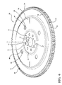
Figure 1 is a perspective view of a flexplate assembly illustrating a central plate and a ring gear according to an aspect of the disclosure; -
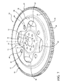
Figure 2 is a perspective view of a flexplate assembly illustrating a central plate, a ring gear, and a noise plate according to an aspect of the disclosure; -
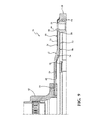
Figure 3 is a partial side cross-sectional view of a flexplate assembly illustrating a noise plate according to an aspect of the disclosure; -
Figure 4 is a partial perspective cross-sectional view of the noise plate shown inFIG. 3 ; -
Figure 5 is a perspective view of a flexplate assembly illustrating a central plate, a ring gear, and a noise plate according to an aspect of the disclosure; -
Figure 6 is a perspective view of a flexplate assembly illustrating a central plate, a ring gear, and a noise plate according to an aspect of the disclosure; -
Figure 7 is a perspective view of a flexplate assembly illustrating a central plate, a ring gear, and a noise plate according to an aspect of the disclosure; -
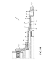
Figure 8A is an exploded cross-sectional view of a flexplate assembly according to an aspect of the disclosure; -
Figure 8B is a partial side cross-sectional view of the flexplate assembly shown inFIG. 8A ; -
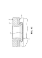
Figure 8C is an enlarged partial cross-sectional view of the flexplate assembly shown inFIG. 8A illustrating a plate fastener; -
Figure 9 is a partial side cross-sectional view of a flexplate assembly according to an aspect of the disclosure; -
Figure 10 is an enlarged partial cross-sectional view of a central plate and noise plate of a flexplate assembly according to an aspect of the disclosure illustrating an additional damping material; -
Figure 11 is an enlarged partial perspective view of a flexplate assembly according to an aspect of the disclosure illustrating a pair of noise plates; -
Figure 12A is a perspective view of a central plate of a flexplate assembly according to an aspect of the disclosure; -
Figure 12B is a perspective view of a ring gear of a flexplate assembly according to an aspect of the disclosure; -
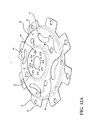
Figure 12C is a perspective view of a flexplate assembly according to an aspect of the disclosure; -
Figures 13A - 13B are graphs illustrating testing results of flexplate assemblies according to aspects of the disclosure; -
Figure 14 is a graph illustrating noise emitted from a flexplate assembly according to an aspect of the disclosure; and -
Figure 15 is a flow chart illustrating the steps of constructing a flexplate assembly according to an aspect of the disclosure. - In the following description, details are set forth to provide an understanding of the present disclosure. In some instances, certain structures and techniques have not been described or shown in detail in order not to obscure the disclosure.
- In general, the present disclosure relates to flexplate assemblies used for conveying rotational energy in various power operated devices of the type well-suited for use in many applications. The flexplate assembly of this disclosure will be described in conjunction with one or more example embodiments. However, the specific example embodiments disclosed are merely provided to describe the inventive concepts, features, advantages and objectives will sufficient clarity to permit those skilled in this art to understand and practice the disclosure.
- Referring to the Figures, wherein like numerals indicate corresponding parts throughout the several views, a
flexplate assembly flexplate assembly central plate 22 that has a generally disc shape that is disposed about and extends radially from an axis A and presents atop surface 23 and abottom surface 24. Aring gear 26 is disposed annularly about thecentral plate 22 and presents anouter circumference 28. Theouter circumference 28 of thering gear 26 presents a plurality ofring teeth 30 that extend radially therefrom for engaging pinion teeth of a pinion gear (not shown) coupled to a starter of an automobile to rotate theflexplate assembly - According to an aspect of the disclosure, the
central plate 22 extends radially from the axis A from aninner portion 32, to anintermediate portion 34, to anouter portion 36, as best shown inFIG. 1 . Theinner portion 32 has a generally hemispherical cross-sectional shape. Theintermediate portion 34 is stepped axially from the inner andouter portions outer portion 36 defines a plurality ofmounting apertures 38 circumferentially and evenly spaced from one another about theouter portion 36 for receiving a plurality of first mounting bolts (not shown) for securing theflexplate assembly 20 to a torque convertor (not shown). Theouter portion 36 may also definesecondary apertures 39 for reducing the weight of thecentral plate 22. According to an aspect, an insert 40 (FIGS. 8B and9A) may also be disposed in each mountingaperture 38 to provide a more secure attachment between theflexplate assembly 20 and the torque convertor. - The
inner portion 32 defines acentral opening 42 extending through thecentral plate 22 along the axis A for receiving and securing theflexplate assembly 20 to a crankshaft (not shown). Theinner portion 32 of thecentral plate 22 defines a plurality of attachingapertures 44 circumferentially and evenly spaced from one another about theinner portion 32 for receiving a plurality of second mounting bolts for securing theflexplate assembly 20 to a hub 45 (FIG. 3 ) of the crankshaft. - The
intermediate portion 34 of thecentral plate 22 defines a plurality offirst slots 46 that have a kidney shape and are circumferentially and evenly spaced about theintermediate portion 34 for providing for flexibility and reduced weight of thecentral plate 22. Theintermediate portion 34 of thecentral plate 22 further defines a plurality ofsecond slots 48 that have a circular shape and are circumferentially and evenly spaced about theintermediate portion 34 for also providing for reduced weight of thecentral plate 22. It should be appreciated that more orfewer apertures slots central plate 22 to accommodate for other configurations of thecentral plate 22. - As best shown in
FIGS. 2-11 , theflexplate assembly 20 further includes anoise plate 50 that is disposed adjacent to thecentral plate 22 and extends circumferentially about the axis A for reducing vibrations and noise from theflexplate assembly 20. While vibrations and noise from theflexplate assembly 20 may primarily occur for example during starting of the automobile when the pinion gears of the starter of the automobile impact thering teeth 30 of thering gear 26 of theflexplate assembly 20, it should be understood that thenoise plate 50 may reduce vibrations and noise at other times. In the disclosed embodiments, thenoise plate 50 is made of a steel material but it should be appreciated that thenoise plate 50 could be made of other materials such as, but not limited to, aluminum or plastics. In the disclosed embodiments, thenoise plate 50 is frictionally engaged with and slideably moveable relative to thecentral plate 22 and/orring gear 26 to reduce noise and reduce vibrations during starting of the automobile by converting friction into heat. In other words, thenoise plate 50 is frictionally engaged with the central plate and/orring gear 26 for permitting limited sliding movement of thenoise plate 50 relative to thecentral plate 22 and/orring gear 26. Thenoise plate 50 andcentral plate 22 and/orring gear 26 may move relative to one another in radial, axial, and/or angular directions depending on the design of thecentral plate 22 andnoise plate 50. - According to an aspect of the disclosure, the
noise plate 50 could be constructed in various shapes and configurations. In embodiments shown inFIGS. 2-4 , thenoise plate 50 generally has a ring shape and includes aflange 52 and alower lip 54 extending generally axially and radially outwardly from theflange 52 to a maximum deflection zone adjacent to thering teeth 30 of thering gear 26. It should be appreciated that thenoise plate 50 could also extend between thering gear 26 and thecentral plate 22. In further embodiments best shown inFIGS. 5-7 , thenoise plate 50 also includes anupper lip 56 that extends generally axially away from and radially inwardly from theflange 52 toward the axis A (i.e. crankshaft centerline). By extending thenoise plate 50 into the maximum deflection zone and/or inwardly toward the axis A, the effective noise plate-to-central plate sliding interface or surface area may be increased which consequently provides for maximum noise reduction by conversion of friction to heat. Additionally,noise plate 50 may define a plurality ofapertures 58 extending through thenoise plate 50. According to an aspect, theupper lip 56 defines amiddle opening 60 about the axis A. In the embodiment disclosed inFIG. 6 , theupper lip 56 definesapertures 58 which are aligned with theupper slots 48 of thecentral plate 22. Additionally, in the embodiment ofFIG. 7 , themiddle opening 60 has a general cross shape. - It should be appreciated that the
flange 52,lower lip 54, andupper lip 56 of thenoise plate 50 could have various shapes and sizes to increase relative sliding between thenoise plate 50 andcentral plate 22 and/orring gear 26 to provide for increased reduction of noise and vibrations through increased conversion of friction to heat. Additionally, it should be appreciated that thenoise plate 50 could engage to thecentral plate 22 and/orring gear 26 with or without tabs (i.e. fingers). According to an aspect, the tabs could extend from thenoise plate 50 toward the periphery of thecentral plate 22 orring gear 26 to provide spring-like compressive forces on thering gear 26 for increased friction to heat conversion and to provide for additional impact cushioning and compliance. According to another aspect, thenoise plate 50 may also be preshaped, whereby its periphery or tabs provide spring-like compressive force on thecentral plate 22 orring gear 26 once assembled with thecentral plate 22 and thering gear 26. The perimeter of theflexplate assembly noise plate 50 may primarily engage thecentral plate 22 at its periphery, according to an aspect, it could fully or partially engage it at other locations. Additionally, a surface treatment, texture, or coating may be applied to regions of or theentire noise plate 50,central plate 22, and/orring gear 26 in order to alter the friction coefficient between thenoise plate 50, thecentral plate 22, and/or thering gear 26. Furthermore, while thenoise plate 50 can be disposed adjacent to thetop surface 23 of the central plate 22 (FIGS. 2-7 ), it should be appreciated that thenoise plate 50 could be positioned adjacent to thebottom surface 24, as illustrated inFIGS. 8A- 8C . - The
noise plate 50 may be attached to thecentral plate 22 usingvarious plate fasteners 61. According to an aspect, theplate fasteners 61 are a plurality of clinched areas 61 (e.g. Tog-L-Loc®) spaced from one another and disposed circumferentially about theouter portion 36 of thecentral plate 22, as best shown inFIGS. 2 ,8A and8C . It should be understood that theplate fasteners 61 may alternatively comprise other fasteners such as, but not limited to epoxy, spot welding, rivets, or bolts. According to an aspect, thenoise plate 50 may also be snap fit to thecentral plate 22. According to another aspect, thenoise plate 50 may be partially and peripherally joined to thecentral plate 22 and/orring gear 26. - According to an aspect of the disclosure, one
noise plate 50 may also be disposed adjacent to thetop surface 23 of thecentral plate 22 and anothernoise plate 50 may be disposed adjacent to thebottom surface 24 as best shown inFIGS. 9A-9C . Furthermore, as best presented inFIG. 10 , an additional dampingmaterial 62, such as but not limited to an organic polymeric material, could be disposed between thenoise plate 50 andcentral plate 22 and/orring gear 26 to provide for additional noise and vibration reduction. According to another aspect, theflexplate assembly 20 includes a plurality ofnoise plates 50 both disposed adjacent to thetop surface 23 of thecentral plate 22, as shown inFIG. 11 . It should be appreciated that the additional dampingmaterial 62 may also be disposed between each of the plurality ofnoise plates 50 which are disposed adjacent to thetop surface 23 of thecentral plate 22. - In an alternate embodiment of the disclosure as best presented in
FIGS. 12A - 12C , theouter portion 36 of thecentral plate 22 is defined by a plurality of first lugs 63 (FIG. 12A ) that extend radially from theintermediate portion 34 of thecentral plate 22 and are circumferentially and evenly spaced from one another about thecentral plate 22. Further, thering gear 26 presents a plurality of second lugs 64 (FIG. 12B ) that extend radially inwardly from theouter circumference 28 and are circumferentially and evenly spaced from one another about thering gear 26. As best shown inFIG. 12C , thecentral plate 22 andring gear 26 may be attached together. Specifically, each of thefirst lugs 63 of thecentral plate 22 overlies one of thesecond lugs 64 of thering gear 26 to coaxially align thecentral plate 22 andring gear 26. Alug fastener 66 connects each of the respective pairs of first andsecond lugs central plate 22 andring gear 26 to one another. In the disclosed embodiment, thelug fasteners 66 are rivets, however, it should be appreciated thatother lug fasteners 66 could be used such as, but not limited to bolts, welding, epoxy, or clinching. According to an aspect of the disclosure, thenoise plate 50 could be connected with thecentral plate 22 and/orring gear 26 in the same ways as for the other disclosed embodiments to form theflexplate assembly 120. It should be appreciated that in this embodiment, to reduce noise and minimize materials used, thecentral plate 22 and thering gear 26 are separated from an original one-piece flexplate. Thesepieces - The
flexplate assemblies FIGS. 13A and13B which illustrate testing results offlex plate assemblies FIGS. 13A and13B ). In order to obtain such testing results, the sound pressure levels, in decibels are recorded during engagement of the gear teeth of the pinion gear with thering teeth 30 of thering gear 26 or computed in a simulation. As illustrated inFIG. 14 , the highest sound pressure levels are typically during initial engagement of the gear teeth of the pinion gear with thering teeth 30 of the ring gear 26 (indicated as "Range 1"), while lower noise levels may be expected while the starter drives continuously (indicated as "Range 2") and once the engine is running ("indicated as "Range 3"). Theflexplate assembly 120 disclosed also advantageously provides for a design that uses fewer materials and reduces waste during manufacturing in comparison to previous techniques whereby thecentral plate 22 and/orring gear 26 andnoise plate 50 are blanked (e.g. stamped) separately. However, it should be appreciated that thecentral plate 22,ring gear 26, andnoise plate 50 may alternatively be blanked or constructed separately. - As illustrated by a flow chart in
FIG. 15 , a method of constructing a method of constructing aflexplate assembly central plate 22. The method proceeds by 202 forming aring gear 26 about thecentral plate 22. As discussed above, thecentral plate 22 andring gear 26 may originally begin as a one-piece flexplate which is separated and refastened. Consequently, the step of forming thering gear 26 about thecentral plate 22 can include the steps of forming aring gear 26 about thecentral plate 22, cutting thecentral plate 22 to form a plurality offirst lugs 63 extending radially outwardly from thecentral plate 22 and a plurality ofsecond lugs 64 extending radially inwardly from thering gear 26, rotationally displacing thering gear 26 and thecentral plate 22 to align thefirst lugs 63 and thesecond lugs 64, and securing thering gear 26 to thecentral plate 22 at thelugs ring gear 26 could be formed about thecentral plate 22 using other manufacturing techniques such as, but not limited to welding or casting. The next step of the method is 204 forming at least onenoise plate 50. Thenoise plate 50 may be formed using any manufacturing technique such as, but not limited to stamping, molding, or casting. The method concludes with the step of 206 attaching thenoise plate 50 to thecentral plate 22 andring gear 26, wherein thenoise plate 50 is frictionally engaged with and slideably moveable relative to thecentral plate 22 andring gear 26. As disclosed above, thenoise plate 50 can attached to thecentral plate 22 and/orring gear 26 usingvarious plate fasteners 61. Therefore, the method may include steps such as, but not limited to applying epoxy, welding, riveting, or bolting. According to an aspect, the step of 206 attaching thenoise plate 50 to thecentral plate 22 andring gear 26 is further defined as clinching thecentral plate 22 andnoise plate 50 to form plate fasteners 61 (e.g. Tog-L-Loc®) spaced from one another and disposed circumferentially about thecentral plate 22. - The foregoing description of the embodiments has been provided for purposes of illustration and description. It is not intended to be exhaustive or to limit the disclosure. Individual elements or features of a particular embodiment are generally not limited to that particular embodiment, but, where applicable, are interchangeable and can be used in a selected embodiment, even if not specifically shown or described. The same may also be varied in many ways. Such variations are not to be regarded as a departure from the disclosure, and all such modifications are intended to be included within the scope of the disclosure. Those skilled in the art will recognize that concepts disclosed in association with an example switching system can likewise be implemented into many other systems to control one or more operations and/or functions.
- Example embodiments are provided so that this disclosure will be thorough, and will fully convey the scope to those who are skilled in the art. Numerous specific details are set forth such as examples of specific components, devices, and methods, to provide a thorough understanding of embodiments of the present disclosure. It will be apparent to those skilled in the art that specific details need not be employed, that example embodiments may be embodied in many different forms and that neither should be construed to limit the scope of the disclosure. In some example embodiments, well-known processes, well-known device structures, and well-known technologies are not described in detail.
- The terminology used herein is for the purpose of describing particular example embodiments only and is not intended to be limiting. As used herein, the singular forms "a," "an," and "the" may be intended to include the plural forms as well, unless the context clearly indicates otherwise. The terms "comprises," "comprising," "including," and "having," are inclusive and therefore specify the presence of stated features, integers, steps, operations, elements, and/or components, but do not preclude the presence or addition of one or more other features, integers, steps, operations, elements, components, and/or groups thereof. The method steps, processes, and operations described herein are not to be construed as necessarily requiring their performance in the particular order discussed or illustrated, unless specifically identified as an order of performance. It is also to be understood that additional or alternative steps may be employed.
- When an element or layer is referred to as being "on," "engaged to," "connected to," or "coupled to" another element or layer, it may be directly on, engaged, connected or coupled to the other element or layer, or intervening elements or layers may be present. In contrast, when an element is referred to as being "directly on," "directly engaged to," "directly connected to," or "directly coupled to" another element or layer, there may be no intervening elements or layers present. Other words used to describe the relationship between elements should be interpreted in a like fashion (e.g., "between" versus "directly between," "adjacent" versus "directly adjacent," etc.). As used herein, the term "and/or" includes any and all combinations of one or more of the associated listed items.
- Although the terms first, second, third, etc. may be used herein to describe various elements, components, regions, layers and/or sections, these elements, components, regions, layers and/or sections should not be limited by these terms. These terms may be only used to distinguish one element, component, region, layer or section from another region, layer or section. Terms such as "first," "second," and other numerical terms when used herein do not imply a sequence or order unless clearly indicated by the context. Thus, a first element, component, region, layer or section discussed below could be termed a second element, component, region, layer or section without departing from the teachings of the example embodiments.
- Spatially relative terms, such as "inner," "outer," "beneath," "below," "lower," "above," "upper," and the like, may be used herein for ease of description to describe one element or feature's relationship to another element(s) or feature(s) as illustrated in the figures. Spatially relative terms may be intended to encompass different orientations of the device in use or operation in addition to the orientation depicted in the figures. For example, if the device in the figures is turned over, elements described as "below" or "beneath" other elements or features would then be oriented "above" the other elements or features. Thus, the example term "below" can encompass both an orientation of above and below. The device may be otherwise oriented (rotated degrees or at other orientations) and the spatially relative descriptions used herein interpreted accordingly.
- Obviously, many modifications and variations of the present invention are possible in light of the above teachings and may be practiced otherwise than as specifically described while within the scope of the appended claims.
Claims (20)
- A flexplate assembly comprising;
a central plate having a general disc shape disposed about and extending radially from an axis,
a ring gear annularly secured about said central plate and presenting an outer circumference defining a plurality of ring teeth extending therefrom,
at least one noise plate disposed adjacent to said central plate and extending circumferentially about said axis for reducing vibrations and noise from said flexplate assembly, and
said noise plate being frictionally engaged with and slideably moveable relative to said central plate for reducing noise and reduce vibrations by converting friction between said noise plate and said central plate into heat. - A flexplate assembly as in claim 1, further including a plurality of plate fasteners spaced from one another and disposed circumferentially about said axis to attach said noise plate to said central plate.
- A flexplate assembly as in claim 2, wherein said plurality of plate fasteners each comprising a clinched area.
- A flexplate assembly as in claim 2, wherein said plate fasteners include at least one of the following: epoxy, weld, rivet, screw, or bolt.
- A flexplate assembly as in claim 1, wherein said noise plate further includes tabs extending from the noise plate toward at least one of said central plate and said ring gear to provide spring-like compressive forces for increased friction to heat conversion and to provide for additional impact cushioning and compliance.
- A flexplate assembly as in claim 1 further including an additional damping material disposed between said noise plate and at least one of said central plate and said ring gear to provide for additional noise and vibration reduction.
- A flexplate assembly as in claim 1, wherein said noise plate is preshaped and provides spring-like compressive force on at least one of said central plate and said ring gear once assembled with said central plate and said ring gear.
- A flexplate assembly as in claim 1, wherein said central plate presents a top surface and a bottom surface and said noise plate comprises at least one noise plate disposed adjacent said top surface and at least one noise plate is disposed adjacent said bottom surface.
- A flexplate assembly as in claim 1, wherein said noise plate comprises a plurality of noise plates disposed adjacent one another and adjacent one of said top surface and said bottom surface.
- A flexplate assembly as in claim 9, further including a damping material disposed between each of said plurality of noise plates.
- A flexplate assembly as in claim 1, wherein said central plate extends radially from an inner portion having a generally hemispherical cross-section to an intermediate portion stepped axially from said inner portion to an outer portion.
- A flexplate assembly as in claim 11, wherein said central plate defines a plurality of slots disposed circumferentially about said intermediate portion for providing flexibility and reducing weight of said central plate.
- A flexplate assembly as in claim 1, wherein said noise plate includes a flange and a lower lip extending generally axially and radially outwardly from said flange to a maximum deflection zone adjacent said ring teeth of said ring gear.
- A flexplate assembly as in claim 13, wherein said noise plate further includes an upper lip extending generally axially away from and radially inwardly from said flange toward said axis.
- A flexplate assembly as in claim 1, wherein at least one of said noise plate and said central plate and said ring gear includes a surface treatment in order to alter the friction coefficient between said noise plate and said central plate and said ring gear.
- A method of constructing a flexplate assembly comprising the steps of:forming a central plate,forming a ring gear about the central plate,forming at least one noise plate, andattaching the noise plate to the central plate and ring gear, wherein the noise plate is frictionally engaged with and slideably moveable relative to the central plate and ring gear.
- The method of claim 16 wherein the step of forming the ring gear about the central plate is further defined as;
forming a ring gear about the central plate,
cutting the central plate to form a plurality of first lugs extending radially outwardly from the central plate and a plurality of second lugs extending radially inwardly from the ring gear,
rotationally displacing the ring gear and the central plate to align the first lugs and the second lugs, and
securing the ring gear to the central plate at the lugs. - The method of claim 17 wherein the step of securing the ring gear to the central plate at the lugs is further defined as riveting the first lugs to the second lugs.
- The method of claim 16 wherein the step of attaching the noise plate to the central plate and ring gear is further defined as clinching the central plate and noise plate to form a plurality of plate fasteners spaced from one another and disposed circumferentially about the central plate.
- The method of claim 16 wherein the step of attaching the noise plate to the central plate and ring gear is further defined as attaching one noise plate adjacent to a top surface of the central plate and attaching another noise plate adjacent to a bottom surface of the central plate.
Applications Claiming Priority (2)
| Application Number | Priority Date | Filing Date | Title |
|---|---|---|---|
| US201462046019P | 2014-09-04 | 2014-09-04 | |
| US201462046454P | 2014-09-05 | 2014-09-05 |
Publications (2)
| Publication Number | Publication Date |
|---|---|
| EP3023662A1 true EP3023662A1 (en) | 2016-05-25 |
| EP3023662B1 EP3023662B1 (en) | 2018-11-14 |
Family
ID=55437139
Family Applications (1)
| Application Number | Title | Priority Date | Filing Date |
|---|---|---|---|
| EP15182006.5A Active EP3023662B1 (en) | 2014-09-04 | 2015-08-21 | Reduced noise flexplate |
Country Status (4)
| Country | Link |
|---|---|
| US (2) | US10060503B2 (en) |
| EP (1) | EP3023662B1 (en) |
| CN (1) | CN105402311B (en) |
| CA (1) | CA2900376A1 (en) |
Cited By (1)
| Publication number | Priority date | Publication date | Assignee | Title |
|---|---|---|---|---|
| RU2641351C1 (en) * | 2016-10-14 | 2018-01-17 | Федеральное государственное унитарное предприятие "Центральный институт авиационного моторостроения имени П.И. Баранова" | Gear wheel |
Families Citing this family (15)
| Publication number | Priority date | Publication date | Assignee | Title |
|---|---|---|---|---|
| US8561283B1 (en) | 2007-10-29 | 2013-10-22 | Prestolite Performance, Llc | Method to provide a universal bellhousing between an engine and transmission of a vehicle |
| US9482308B2 (en) | 2011-01-26 | 2016-11-01 | Accel Performance Group Llc | Automotive flywheel with fins to increase airflow through clutch, method of making same, and heat management method |
| US20120186936A1 (en) | 2011-01-26 | 2012-07-26 | Prestolite Performance Llc. | Clutch assembly cover, method of making same, and optional heat management |
| US9982748B2 (en) * | 2012-12-12 | 2018-05-29 | Magna International | Flexplates and method for capacitor discharge welding of flexplates |
| US10502306B1 (en) | 2016-04-25 | 2019-12-10 | Accel Performance Group Llc | Bellhousing alignment device and method |
| US20180142735A1 (en) * | 2016-11-18 | 2018-05-24 | GM Global Technology Operations LLC | Composite flange for a vehicle |
| DE102017109726A1 (en) * | 2017-05-05 | 2018-11-08 | Mühlhoff Umformtechnik GmbH | Method for producing a flywheel |
| CN107328644B (en) * | 2017-07-20 | 2024-03-26 | 广州广日电梯工业有限公司 | Composite material scratch test device |
| DE102018106271A1 (en) * | 2018-03-19 | 2019-09-19 | Schaeffler Technologies AG & Co. KG | centrifugal pendulum |
| US11173568B2 (en) | 2018-07-11 | 2021-11-16 | GM Global Technology Operations LLC | Composite metal flexplate |
| AT521959B1 (en) * | 2019-01-04 | 2020-07-15 | Miba Sinter Austria Gmbh | gear |
| CN109723730A (en) * | 2019-01-29 | 2019-05-07 | 陕西中大机械集团有限责任公司 | a coupling |
| DE102019134274B3 (en) * | 2019-12-13 | 2021-03-18 | Schaeffler Technologies AG & Co. KG | Starter device with a tensioning spring element |
| CN112984763B (en) * | 2019-12-16 | 2025-04-18 | 青岛海尔空调器有限总公司 | Air guide mechanism of air conditioner and air conditioner indoor unit having the same |
| CN113236734B (en) * | 2021-05-11 | 2022-08-19 | 中国船舶重工集团公司第七0三研究所 | Variable-rigidity vibration reduction gear |
Citations (3)
| Publication number | Priority date | Publication date | Assignee | Title |
|---|---|---|---|---|
| US5323665A (en) * | 1993-07-19 | 1994-06-28 | General Motors Corporation | Starting vibration damped flexplate flywheel |
| FR2822907A1 (en) * | 2001-03-30 | 2002-10-04 | Mitsubishi Electric Corp | FLYWHEEL WITH A TOOTHED CROWN |
| CN101595326A (en) * | 2006-09-20 | 2009-12-02 | Gif工业研究有限责任公司 | Drive train with main drive shaft and drive train for motor vehicles with drive shaft protruding especially from engine block |
Family Cites Families (9)
| Publication number | Priority date | Publication date | Assignee | Title |
|---|---|---|---|---|
| US2346732A (en) * | 1941-09-20 | 1944-04-18 | Ford Motor Co | Vibration damper |
| US4318283A (en) * | 1979-12-13 | 1982-03-09 | Caterpillar Tractor Co. | Torsional vibration damper assembly |
| FR2723996B1 (en) * | 1994-08-24 | 1996-09-27 | Valeo | TORSION SHOCK ABSORBER, PARTICULARLY FOR MOTOR VEHICLE |
| US6352384B1 (en) | 1999-12-23 | 2002-03-05 | Daimlerchrysler Corporation | Self-locking flexplate |
| JP3769731B2 (en) * | 2002-12-04 | 2006-04-26 | 愛知機械工業株式会社 | Flywheel |
| US20070277643A1 (en) | 2006-06-06 | 2007-12-06 | King Anthony W | Flex Plate with Attached Rim |
| US9032837B2 (en) | 2009-08-05 | 2015-05-19 | Chrysler Group Llc | Pendulum absorber system |
| JP5728186B2 (en) | 2010-09-13 | 2015-06-03 | アイシン機工株式会社 | Drive plate and ring gear member of drive plate |
| US9982748B2 (en) | 2012-12-12 | 2018-05-29 | Magna International | Flexplates and method for capacitor discharge welding of flexplates |
-
2015
- 2015-08-07 US US14/820,625 patent/US10060503B2/en not_active Expired - Fee Related
- 2015-08-14 CA CA2900376A patent/CA2900376A1/en not_active Abandoned
- 2015-08-21 EP EP15182006.5A patent/EP3023662B1/en active Active
- 2015-09-02 CN CN201510556351.5A patent/CN105402311B/en active Active
-
2018
- 2018-08-27 US US16/112,931 patent/US10690219B2/en active Active
Patent Citations (3)
| Publication number | Priority date | Publication date | Assignee | Title |
|---|---|---|---|---|
| US5323665A (en) * | 1993-07-19 | 1994-06-28 | General Motors Corporation | Starting vibration damped flexplate flywheel |
| FR2822907A1 (en) * | 2001-03-30 | 2002-10-04 | Mitsubishi Electric Corp | FLYWHEEL WITH A TOOTHED CROWN |
| CN101595326A (en) * | 2006-09-20 | 2009-12-02 | Gif工业研究有限责任公司 | Drive train with main drive shaft and drive train for motor vehicles with drive shaft protruding especially from engine block |
Cited By (1)
| Publication number | Priority date | Publication date | Assignee | Title |
|---|---|---|---|---|
| RU2641351C1 (en) * | 2016-10-14 | 2018-01-17 | Федеральное государственное унитарное предприятие "Центральный институт авиационного моторостроения имени П.И. Баранова" | Gear wheel |
Also Published As
| Publication number | Publication date |
|---|---|
| CN105402311A (en) | 2016-03-16 |
| US10690219B2 (en) | 2020-06-23 |
| CN105402311B (en) | 2019-06-14 |
| EP3023662B1 (en) | 2018-11-14 |
| CA2900376A1 (en) | 2016-03-04 |
| US20160069416A1 (en) | 2016-03-10 |
| US10060503B2 (en) | 2018-08-28 |
| US20180363726A1 (en) | 2018-12-20 |
Similar Documents
| Publication | Publication Date | Title |
|---|---|---|
| EP3023662B1 (en) | Reduced noise flexplate | |
| US20160109010A1 (en) | Hybrid drive module with optimized electric motor attachment | |
| JP6738496B2 (en) | Automotive clutch assembly with a stopper to limit lifting of the clutch plate assembly | |
| US20080034918A1 (en) | Multi-mode vibration damper having a spoked hub | |
| US20140329629A1 (en) | One-piece inertia ring and method of manufacturing the one-piece inertia ring | |
| US20190126738A1 (en) | Hybrid module | |
| US20170268600A1 (en) | Support for a pendulum damping device, and pendulum damping device comprising such a support | |
| EP2059689B1 (en) | Flexplate coupling for a wet clutch transmission | |
| US6186898B1 (en) | Elastic coupling device between two substantially aligned shafts | |
| KR20170010726A (en) | Double damping flywheel comprising a sealing washer capable of ensuring sealing of the primary flywheel | |
| US7757828B2 (en) | Clutch attached to an outer rim of a torque converter | |
| CN113494563A (en) | Torsional vibration damper and method for assembling a torsional vibration damper | |
| US20150040550A1 (en) | Cover assembly for a torque converter including drive plate having elastic preloading element | |
| US20100059324A1 (en) | Coupling Arrangement, Particularly for a Hydrodynamic Coupling Device | |
| US11339861B2 (en) | Turbine assembly, hydrokinetic torque converter, and methods for making the same | |
| US20060245936A1 (en) | Bonding method for elastic member and metal, and power transmission device | |
| US20160160958A1 (en) | Pendulum damping device for a motor vehicle torque transmission device | |
| WO2018080883A1 (en) | Motor vehicle clutch assembly including shock absorber for smoothing clutch engagement | |
| US11333217B2 (en) | Drive assembly including hub assembly extension | |
| US9360097B2 (en) | Lanced drive plate | |
| US9976624B2 (en) | Damper and pre-damper assembly | |
| US9689461B2 (en) | Damper assebmly sealing arrangement | |
| US10107356B2 (en) | Torque converter including damper assembly with hysteresis control package | |
| US20180135737A1 (en) | Turbine assembly for hydrokinetic torque converter, and method for making the same | |
| US7481050B2 (en) | Hydrodynamic torque converter |
Legal Events
| Date | Code | Title | Description |
|---|---|---|---|
| AK | Designated contracting states |
Kind code of ref document: A1 Designated state(s): AL AT BE BG CH CY CZ DE DK EE ES FI FR GB GR HR HU IE IS IT LI LT LU LV MC MK MT NL NO PL PT RO RS SE SI SK SM TR |
|
| AX | Request for extension of the european patent |
Extension state: BA ME |
|
| PUAI | Public reference made under article 153(3) epc to a published international application that has entered the european phase |
Free format text: ORIGINAL CODE: 0009012 |
|
| 17P | Request for examination filed |
Effective date: 20160601 |
|
| RBV | Designated contracting states (corrected) |
Designated state(s): AL AT BE BG CH CY CZ DE DK EE ES FI FR GB GR HR HU IE IS IT LI LT LU LV MC MK MT NL NO PL PT RO RS SE SI SK SM TR |
|
| GRAP | Despatch of communication of intention to grant a patent |
Free format text: ORIGINAL CODE: EPIDOSNIGR1 |
|
| STAA | Information on the status of an ep patent application or granted ep patent |
Free format text: STATUS: GRANT OF PATENT IS INTENDED |
|
| RIC1 | Information provided on ipc code assigned before grant |
Ipc: F16F 15/30 20060101ALI20180622BHEP Ipc: F16D 65/00 20060101ALI20180622BHEP Ipc: F16D 3/50 20060101AFI20180622BHEP Ipc: F16F 15/129 20060101ALI20180622BHEP Ipc: F16D 3/14 20060101ALI20180622BHEP Ipc: F16F 15/10 20060101ALI20180622BHEP |
|
| INTG | Intention to grant announced |
Effective date: 20180725 |
|
| GRAS | Grant fee paid |
Free format text: ORIGINAL CODE: EPIDOSNIGR3 |
|
| GRAA | (expected) grant |
Free format text: ORIGINAL CODE: 0009210 |
|
| STAA | Information on the status of an ep patent application or granted ep patent |
Free format text: STATUS: THE PATENT HAS BEEN GRANTED |
|
| AK | Designated contracting states |
Kind code of ref document: B1 Designated state(s): AL AT BE BG CH CY CZ DE DK EE ES FI FR GB GR HR HU IE IS IT LI LT LU LV MC MK MT NL NO PL PT RO RS SE SI SK SM TR |
|
| REG | Reference to a national code |
Ref country code: CH Ref legal event code: EP Ref country code: AT Ref legal event code: REF Ref document number: 1065186 Country of ref document: AT Kind code of ref document: T Effective date: 20181115 |
|
| REG | Reference to a national code |
Ref country code: IE Ref legal event code: FG4D |
|
| REG | Reference to a national code |
Ref country code: DE Ref legal event code: R096 Ref document number: 602015019735 Country of ref document: DE |
|
| REG | Reference to a national code |
Ref country code: NL Ref legal event code: MP Effective date: 20181114 |
|
| REG | Reference to a national code |
Ref country code: LT Ref legal event code: MG4D |
|
| REG | Reference to a national code |
Ref country code: AT Ref legal event code: MK05 Ref document number: 1065186 Country of ref document: AT Kind code of ref document: T Effective date: 20181114 |
|
| PG25 | Lapsed in a contracting state [announced via postgrant information from national office to epo] |
Ref country code: NO Free format text: LAPSE BECAUSE OF FAILURE TO SUBMIT A TRANSLATION OF THE DESCRIPTION OR TO PAY THE FEE WITHIN THE PRESCRIBED TIME-LIMIT Effective date: 20190214 Ref country code: BG Free format text: LAPSE BECAUSE OF FAILURE TO SUBMIT A TRANSLATION OF THE DESCRIPTION OR TO PAY THE FEE WITHIN THE PRESCRIBED TIME-LIMIT Effective date: 20190214 Ref country code: HR Free format text: LAPSE BECAUSE OF FAILURE TO SUBMIT A TRANSLATION OF THE DESCRIPTION OR TO PAY THE FEE WITHIN THE PRESCRIBED TIME-LIMIT Effective date: 20181114 Ref country code: AT Free format text: LAPSE BECAUSE OF FAILURE TO SUBMIT A TRANSLATION OF THE DESCRIPTION OR TO PAY THE FEE WITHIN THE PRESCRIBED TIME-LIMIT Effective date: 20181114 Ref country code: LV Free format text: LAPSE BECAUSE OF FAILURE TO SUBMIT A TRANSLATION OF THE DESCRIPTION OR TO PAY THE FEE WITHIN THE PRESCRIBED TIME-LIMIT Effective date: 20181114 Ref country code: FI Free format text: LAPSE BECAUSE OF FAILURE TO SUBMIT A TRANSLATION OF THE DESCRIPTION OR TO PAY THE FEE WITHIN THE PRESCRIBED TIME-LIMIT Effective date: 20181114 Ref country code: LT Free format text: LAPSE BECAUSE OF FAILURE TO SUBMIT A TRANSLATION OF THE DESCRIPTION OR TO PAY THE FEE WITHIN THE PRESCRIBED TIME-LIMIT Effective date: 20181114 Ref country code: IS Free format text: LAPSE BECAUSE OF FAILURE TO SUBMIT A TRANSLATION OF THE DESCRIPTION OR TO PAY THE FEE WITHIN THE PRESCRIBED TIME-LIMIT Effective date: 20190314 Ref country code: ES Free format text: LAPSE BECAUSE OF FAILURE TO SUBMIT A TRANSLATION OF THE DESCRIPTION OR TO PAY THE FEE WITHIN THE PRESCRIBED TIME-LIMIT Effective date: 20181114 |
|
| PG25 | Lapsed in a contracting state [announced via postgrant information from national office to epo] |
Ref country code: PT Free format text: LAPSE BECAUSE OF FAILURE TO SUBMIT A TRANSLATION OF THE DESCRIPTION OR TO PAY THE FEE WITHIN THE PRESCRIBED TIME-LIMIT Effective date: 20190314 Ref country code: NL Free format text: LAPSE BECAUSE OF FAILURE TO SUBMIT A TRANSLATION OF THE DESCRIPTION OR TO PAY THE FEE WITHIN THE PRESCRIBED TIME-LIMIT Effective date: 20181114 Ref country code: RS Free format text: LAPSE BECAUSE OF FAILURE TO SUBMIT A TRANSLATION OF THE DESCRIPTION OR TO PAY THE FEE WITHIN THE PRESCRIBED TIME-LIMIT Effective date: 20181114 Ref country code: SE Free format text: LAPSE BECAUSE OF FAILURE TO SUBMIT A TRANSLATION OF THE DESCRIPTION OR TO PAY THE FEE WITHIN THE PRESCRIBED TIME-LIMIT Effective date: 20181114 Ref country code: GR Free format text: LAPSE BECAUSE OF FAILURE TO SUBMIT A TRANSLATION OF THE DESCRIPTION OR TO PAY THE FEE WITHIN THE PRESCRIBED TIME-LIMIT Effective date: 20190215 Ref country code: AL Free format text: LAPSE BECAUSE OF FAILURE TO SUBMIT A TRANSLATION OF THE DESCRIPTION OR TO PAY THE FEE WITHIN THE PRESCRIBED TIME-LIMIT Effective date: 20181114 |
|
| PG25 | Lapsed in a contracting state [announced via postgrant information from national office to epo] |
Ref country code: IT Free format text: LAPSE BECAUSE OF FAILURE TO SUBMIT A TRANSLATION OF THE DESCRIPTION OR TO PAY THE FEE WITHIN THE PRESCRIBED TIME-LIMIT Effective date: 20181114 Ref country code: PL Free format text: LAPSE BECAUSE OF FAILURE TO SUBMIT A TRANSLATION OF THE DESCRIPTION OR TO PAY THE FEE WITHIN THE PRESCRIBED TIME-LIMIT Effective date: 20181114 Ref country code: CZ Free format text: LAPSE BECAUSE OF FAILURE TO SUBMIT A TRANSLATION OF THE DESCRIPTION OR TO PAY THE FEE WITHIN THE PRESCRIBED TIME-LIMIT Effective date: 20181114 Ref country code: DK Free format text: LAPSE BECAUSE OF FAILURE TO SUBMIT A TRANSLATION OF THE DESCRIPTION OR TO PAY THE FEE WITHIN THE PRESCRIBED TIME-LIMIT Effective date: 20181114 |
|
| REG | Reference to a national code |
Ref country code: DE Ref legal event code: R097 Ref document number: 602015019735 Country of ref document: DE |
|
| PG25 | Lapsed in a contracting state [announced via postgrant information from national office to epo] |
Ref country code: EE Free format text: LAPSE BECAUSE OF FAILURE TO SUBMIT A TRANSLATION OF THE DESCRIPTION OR TO PAY THE FEE WITHIN THE PRESCRIBED TIME-LIMIT Effective date: 20181114 Ref country code: SM Free format text: LAPSE BECAUSE OF FAILURE TO SUBMIT A TRANSLATION OF THE DESCRIPTION OR TO PAY THE FEE WITHIN THE PRESCRIBED TIME-LIMIT Effective date: 20181114 Ref country code: SK Free format text: LAPSE BECAUSE OF FAILURE TO SUBMIT A TRANSLATION OF THE DESCRIPTION OR TO PAY THE FEE WITHIN THE PRESCRIBED TIME-LIMIT Effective date: 20181114 Ref country code: RO Free format text: LAPSE BECAUSE OF FAILURE TO SUBMIT A TRANSLATION OF THE DESCRIPTION OR TO PAY THE FEE WITHIN THE PRESCRIBED TIME-LIMIT Effective date: 20181114 |
|
| PLBE | No opposition filed within time limit |
Free format text: ORIGINAL CODE: 0009261 |
|
| STAA | Information on the status of an ep patent application or granted ep patent |
Free format text: STATUS: NO OPPOSITION FILED WITHIN TIME LIMIT |
|
| 26N | No opposition filed |
Effective date: 20190815 |
|
| PG25 | Lapsed in a contracting state [announced via postgrant information from national office to epo] |
Ref country code: SI Free format text: LAPSE BECAUSE OF FAILURE TO SUBMIT A TRANSLATION OF THE DESCRIPTION OR TO PAY THE FEE WITHIN THE PRESCRIBED TIME-LIMIT Effective date: 20181114 |
|
| PG25 | Lapsed in a contracting state [announced via postgrant information from national office to epo] |
Ref country code: TR Free format text: LAPSE BECAUSE OF FAILURE TO SUBMIT A TRANSLATION OF THE DESCRIPTION OR TO PAY THE FEE WITHIN THE PRESCRIBED TIME-LIMIT Effective date: 20181114 |
|
| GBPC | Gb: european patent ceased through non-payment of renewal fee |
Effective date: 20190821 |
|
| PG25 | Lapsed in a contracting state [announced via postgrant information from national office to epo] |
Ref country code: LU Free format text: LAPSE BECAUSE OF NON-PAYMENT OF DUE FEES Effective date: 20190821 Ref country code: CH Free format text: LAPSE BECAUSE OF NON-PAYMENT OF DUE FEES Effective date: 20190831 Ref country code: LI Free format text: LAPSE BECAUSE OF NON-PAYMENT OF DUE FEES Effective date: 20190831 Ref country code: MC Free format text: LAPSE BECAUSE OF FAILURE TO SUBMIT A TRANSLATION OF THE DESCRIPTION OR TO PAY THE FEE WITHIN THE PRESCRIBED TIME-LIMIT Effective date: 20181114 |
|
| REG | Reference to a national code |
Ref country code: BE Ref legal event code: MM Effective date: 20190831 |
|
| PG25 | Lapsed in a contracting state [announced via postgrant information from national office to epo] |
Ref country code: IE Free format text: LAPSE BECAUSE OF NON-PAYMENT OF DUE FEES Effective date: 20190821 Ref country code: FR Free format text: LAPSE BECAUSE OF NON-PAYMENT OF DUE FEES Effective date: 20190831 |
|
| PG25 | Lapsed in a contracting state [announced via postgrant information from national office to epo] |
Ref country code: BE Free format text: LAPSE BECAUSE OF NON-PAYMENT OF DUE FEES Effective date: 20190831 Ref country code: GB Free format text: LAPSE BECAUSE OF NON-PAYMENT OF DUE FEES Effective date: 20190821 |
|
| PG25 | Lapsed in a contracting state [announced via postgrant information from national office to epo] |
Ref country code: CY Free format text: LAPSE BECAUSE OF FAILURE TO SUBMIT A TRANSLATION OF THE DESCRIPTION OR TO PAY THE FEE WITHIN THE PRESCRIBED TIME-LIMIT Effective date: 20181114 |
|
| PG25 | Lapsed in a contracting state [announced via postgrant information from national office to epo] |
Ref country code: HU Free format text: LAPSE BECAUSE OF FAILURE TO SUBMIT A TRANSLATION OF THE DESCRIPTION OR TO PAY THE FEE WITHIN THE PRESCRIBED TIME-LIMIT; INVALID AB INITIO Effective date: 20150821 Ref country code: MT Free format text: LAPSE BECAUSE OF FAILURE TO SUBMIT A TRANSLATION OF THE DESCRIPTION OR TO PAY THE FEE WITHIN THE PRESCRIBED TIME-LIMIT Effective date: 20181114 |
|
| PG25 | Lapsed in a contracting state [announced via postgrant information from national office to epo] |
Ref country code: MK Free format text: LAPSE BECAUSE OF FAILURE TO SUBMIT A TRANSLATION OF THE DESCRIPTION OR TO PAY THE FEE WITHIN THE PRESCRIBED TIME-LIMIT Effective date: 20181114 |
|
| REG | Reference to a national code |
Ref country code: DE Ref legal event code: R081 Ref document number: 602015019735 Country of ref document: DE Owner name: MAGNA POWERTRAIN INC., CA Free format text: FORMER OWNER: MAGNA POWERTRAIN INC., CONCORD, ONTARIO, CA |
|
| REG | Reference to a national code |
Ref country code: DE Ref legal event code: R082 Ref document number: 602015019735 Country of ref document: DE Representative=s name: EULER, MATTHIAS, DR., DE |
|
| PGFP | Annual fee paid to national office [announced via postgrant information from national office to epo] |
Ref country code: DE Payment date: 20250624 Year of fee payment: 11 |