EP3023535A1 - Laundry treatment appliance with a universal motor - Google Patents
Laundry treatment appliance with a universal motor Download PDFInfo
- Publication number
- EP3023535A1 EP3023535A1 EP14193812.6A EP14193812A EP3023535A1 EP 3023535 A1 EP3023535 A1 EP 3023535A1 EP 14193812 A EP14193812 A EP 14193812A EP 3023535 A1 EP3023535 A1 EP 3023535A1
- Authority
- EP
- European Patent Office
- Prior art keywords
- motor
- mains
- operating condition
- voltage
- power supply
- Prior art date
- Legal status (The legal status is an assumption and is not a legal conclusion. Google has not performed a legal analysis and makes no representation as to the accuracy of the status listed.)
- Granted
Links
Images



Classifications
-
- D—TEXTILES; PAPER
- D06—TREATMENT OF TEXTILES OR THE LIKE; LAUNDERING; FLEXIBLE MATERIALS NOT OTHERWISE PROVIDED FOR
- D06F—LAUNDERING, DRYING, IRONING, PRESSING OR FOLDING TEXTILE ARTICLES
- D06F58/00—Domestic laundry dryers
- D06F58/30—Drying processes
-
- D—TEXTILES; PAPER
- D06—TREATMENT OF TEXTILES OR THE LIKE; LAUNDERING; FLEXIBLE MATERIALS NOT OTHERWISE PROVIDED FOR
- D06F—LAUNDERING, DRYING, IRONING, PRESSING OR FOLDING TEXTILE ARTICLES
- D06F2103/00—Parameters monitored or detected for the control of domestic laundry washing machines, washer-dryers or laundry dryers
- D06F2103/02—Characteristics of laundry or load
- D06F2103/04—Quantity, e.g. weight or variation of weight
-
- D—TEXTILES; PAPER
- D06—TREATMENT OF TEXTILES OR THE LIKE; LAUNDERING; FLEXIBLE MATERIALS NOT OTHERWISE PROVIDED FOR
- D06F—LAUNDERING, DRYING, IRONING, PRESSING OR FOLDING TEXTILE ARTICLES
- D06F2103/00—Parameters monitored or detected for the control of domestic laundry washing machines, washer-dryers or laundry dryers
- D06F2103/14—Supply, recirculation or draining of washing liquid
-
- D—TEXTILES; PAPER
- D06—TREATMENT OF TEXTILES OR THE LIKE; LAUNDERING; FLEXIBLE MATERIALS NOT OTHERWISE PROVIDED FOR
- D06F—LAUNDERING, DRYING, IRONING, PRESSING OR FOLDING TEXTILE ARTICLES
- D06F2103/00—Parameters monitored or detected for the control of domestic laundry washing machines, washer-dryers or laundry dryers
- D06F2103/24—Spin speed; Drum movements
-
- D—TEXTILES; PAPER
- D06—TREATMENT OF TEXTILES OR THE LIKE; LAUNDERING; FLEXIBLE MATERIALS NOT OTHERWISE PROVIDED FOR
- D06F—LAUNDERING, DRYING, IRONING, PRESSING OR FOLDING TEXTILE ARTICLES
- D06F2103/00—Parameters monitored or detected for the control of domestic laundry washing machines, washer-dryers or laundry dryers
- D06F2103/28—Air properties
- D06F2103/34—Humidity
-
- D—TEXTILES; PAPER
- D06—TREATMENT OF TEXTILES OR THE LIKE; LAUNDERING; FLEXIBLE MATERIALS NOT OTHERWISE PROVIDED FOR
- D06F—LAUNDERING, DRYING, IRONING, PRESSING OR FOLDING TEXTILE ARTICLES
- D06F2103/00—Parameters monitored or detected for the control of domestic laundry washing machines, washer-dryers or laundry dryers
- D06F2103/44—Current or voltage
-
- D—TEXTILES; PAPER
- D06—TREATMENT OF TEXTILES OR THE LIKE; LAUNDERING; FLEXIBLE MATERIALS NOT OTHERWISE PROVIDED FOR
- D06F—LAUNDERING, DRYING, IRONING, PRESSING OR FOLDING TEXTILE ARTICLES
- D06F2105/00—Systems or parameters controlled or affected by the control systems of washing machines, washer-dryers or laundry dryers
- D06F2105/46—Drum speed; Actuation of motors, e.g. starting or interrupting
-
- D—TEXTILES; PAPER
- D06—TREATMENT OF TEXTILES OR THE LIKE; LAUNDERING; FLEXIBLE MATERIALS NOT OTHERWISE PROVIDED FOR
- D06F—LAUNDERING, DRYING, IRONING, PRESSING OR FOLDING TEXTILE ARTICLES
- D06F25/00—Washing machines with receptacles, e.g. perforated, having a rotary movement, e.g. oscillatory movement, the receptacle serving both for washing and for centrifugally separating water from the laundry and having further drying means, e.g. using hot air
-
- D—TEXTILES; PAPER
- D06—TREATMENT OF TEXTILES OR THE LIKE; LAUNDERING; FLEXIBLE MATERIALS NOT OTHERWISE PROVIDED FOR
- D06F—LAUNDERING, DRYING, IRONING, PRESSING OR FOLDING TEXTILE ARTICLES
- D06F33/00—Control of operations performed in washing machines or washer-dryers
- D06F33/30—Control of washing machines characterised by the purpose or target of the control
- D06F33/32—Control of operational steps, e.g. optimisation or improvement of operational steps depending on the condition of the laundry
-
- D—TEXTILES; PAPER
- D06—TREATMENT OF TEXTILES OR THE LIKE; LAUNDERING; FLEXIBLE MATERIALS NOT OTHERWISE PROVIDED FOR
- D06F—LAUNDERING, DRYING, IRONING, PRESSING OR FOLDING TEXTILE ARTICLES
- D06F33/00—Control of operations performed in washing machines or washer-dryers
- D06F33/30—Control of washing machines characterised by the purpose or target of the control
- D06F33/47—Responding to irregular working conditions, e.g. malfunctioning of pumps
-
- D—TEXTILES; PAPER
- D06—TREATMENT OF TEXTILES OR THE LIKE; LAUNDERING; FLEXIBLE MATERIALS NOT OTHERWISE PROVIDED FOR
- D06F—LAUNDERING, DRYING, IRONING, PRESSING OR FOLDING TEXTILE ARTICLES
- D06F58/00—Domestic laundry dryers
- D06F58/32—Control of operations performed in domestic laundry dryers
- D06F58/34—Control of operations performed in domestic laundry dryers characterised by the purpose or target of the control
- D06F58/36—Control of operational steps, e.g. for optimisation or improvement of operational steps depending on the condition of the laundry
-
- D—TEXTILES; PAPER
- D06—TREATMENT OF TEXTILES OR THE LIKE; LAUNDERING; FLEXIBLE MATERIALS NOT OTHERWISE PROVIDED FOR
- D06F—LAUNDERING, DRYING, IRONING, PRESSING OR FOLDING TEXTILE ARTICLES
- D06F58/00—Domestic laundry dryers
- D06F58/32—Control of operations performed in domestic laundry dryers
- D06F58/34—Control of operations performed in domestic laundry dryers characterised by the purpose or target of the control
- D06F58/50—Responding to irregular working conditions, e.g. malfunctioning of blowers
Definitions
- the present invention generally relates to a laundry treatment appliance (e.g., a laundry washing and/or drying appliance), both for domestic and professional use. More particularly, the present invention relates to a laundry treatment appliance provided with a universal motor for causing a rotatable drum rotation during laundry load treatment, and a method and system for efficiently feeding electric power to the universal motor based on appliance operating conditions.
- a laundry treatment appliance e.g., a laundry washing and/or drying appliance
- laundry treatment appliances e.g. laundry washing appliances, laundry washing/drying appliances and laundry drying appliances, hereinafter laundry appliances
- laundry appliances make use of a universal motor for rotating their rotatable drum, called also simply "drum” (i.e . the rotatable container arranged inside the laundry appliance wherein a laundry load is placed/housed in order to be washed and/or dried).
- drum i.e . the rotatable container arranged inside the laundry appliance wherein a laundry load is placed/housed in order to be washed and/or dried.
- Universal motor is an electric motor very similar, in construction, to a DC series motor, but, unlike the latter, it can be operated by both AC and DC power supplies (both of them typically derived by a mains power supply).
- Universal motors feature high starting torque and speed, as well as lightweightness and compactness.
- Universal motors which nowadays laundry appliances are equipped with, are mostly operated by an AC electric power, typically by means of a power supply/feeding apparatus comprising a thyristor device (e.g., a TRIAC device) selectively allowing/preventing AC electric power from the mains power supply to be fed to the universal motor.
- a thyristor device e.g., a TRIAC device
- Applicant has ascertained that some conditions may determine incorrect/not-optimal operation of the laundry appliance, and especially of the universal motor.
- An example of such conditions is a significant reductions in the mains power supply below values deemed acceptable for proper operation of the laundry appliance, both frequent (as in geographical areas, such East Europe and Asian countries, wherein the mains power supply is highly unstable and may have fluctuations below nominal values for relatively long period of time), and sporadic (e.g., due to temporary mains power supply failures).
- a reduction in the mains power supply determines poor starting torque of the universal motor (which may lead to a rotation failure of the drum) or a slowing down of the universal motor speed.
- the torque generated by the universal motor may be not high enough to rotate the drum at the desired speed, or to take it into rotation at all.
- Applicant has found that by providing a laundry treatment appliance with an operating condition detecting unit adapted to detect the occurrence of an operating condition of the appliance, and with a power supply apparatus configured to power an universal motor rotating the rotatable drum of the appliance in a first driving mode if a first operating condition is detected, and in a second driving mode if a second operating condition is detected, wherein in the first driving mode the electric voltage provided to the universal motor has a first waveform, and in the second driving mode the electric voltage provided to the universal motor has a second waveform, different from the first waveform, it is possible to effectively rotate the drum even in case of hard working conditions, such as significant reductions in the mains power supply or high amount of laundry loaded in the drum.
- An aspect of the present invention relates to a laundry treatment appliance.
- the laundry treatment appliance comprises:
- said second waveform is a partialized version of said first waveform.
- said voltage provided by said power supply apparatus to the universal motor in the second driving mode is an alternating voltage, said voltage provided by said power supply apparatus to the universal motor in the second driving mode having a direct component for increasing a starting torque of the universal motor when the second operating condition is detected.
- said power supply apparatus is connected or connectable to a mains power supply providing a sinusoidal mains voltage
- said first waveform comprises a sequence of positive-slope and negative-slope sinusoidal portions of said sinusoidal mains voltage
- said second waveform comprising the positive-slope or the negative-slope sinusoidal portions of said first waveform
- said power supply apparatus is connected or connectable to a mains power supply providing a sinusoidal mains voltage, and wherein said second operating condition occurs if the amplitude of said sinusoidal mains voltage is below a first threshold amplitude value.
- said first operating condition occurs if the amplitude of said sinusoidal mains voltage is above a second threshold amplitude value higher than said first threshold amplitude value.
- said second operating condition occurs if the amplitude of said sinusoidal mains voltage drops below the first threshold amplitude value and said first operating condition occurs if the amplitude of said sinusoidal mains voltage rises above said second threshold amplitude value, the universal motor being powered in the current, first or second, driving mode when the amplitude of said sinusoidal mains voltage is between said first and second threshold amplitude values.
- said power supply apparatus is configured to interrupt the powering of said universal motor if the amplitude of said sinusoidal mains voltage is below a third threshold amplitude value lower than said first threshold amplitude value.
- said second operating condition occurs when the amount of laundry load is above a threshold laundry load weight.
- said second operating condition occurs when a water discharge phase is started.
- said second operating condition occurs when the rotation speed of the drum is below a threshold rotation speed.
- the driving apparatus comprises:
- the appliance comprises a laundry washing appliance or a laundry washing/drying appliance or a laundry drying appliance.
- Another aspect of the present invention relates to a method for operating a laundry treatment appliance comprising a drum for housing a laundry load to be treated, a universal motor adapted to be powered by a voltage for causing drum rotation, an operating condition detecting unit adapted to detect the occurrence of an operating condition of said appliance, a power supply apparatus configured to power the universal motor in a first driving mode in which the voltage provided by said power supply apparatus to the universal motor has a first waveform, and in a second driving mode in which the voltage provided by said power supply apparatus to the universal motor has a second waveform different from said first waveform, said method comprising the steps of:
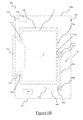
- Figures 1A and 1B show isometric and cross-sectional views, respectively, of a laundry appliance 100 according to an embodiment of the present invention.
- the laundry appliance 100 is an appliance for treating a laundry load (e.g., a laundry washing appliance or a laundry washing/drying appliance), for example of the front-loading type - anyway, as should be apparent from the following description, laundry appliances of the top-loading type may also benefit from the present invention.
- a laundry load e.g., a laundry washing appliance or a laundry washing/drying appliance
- the laundry appliance 100 preferably comprises a substantially parallepiped-shaped cabinet 105, which encloses an inner compartment.
- the inner compartment accommodates a number of well-known electronic, electro-hydraulic, mechanical and/or electro-mechanical components (only the relevant ones to the understanding of the present invention being introduced and discussed in the following).
- the inner compartment accommodates a tub 110 (shown in Figure 1B ), preferably substantially cylindrically-shaped, and, within the tub 110, a rotatable drum 115, preferably substantially cylindrically-shaped, intended to house a laundry load to be washed and/or dried and to rotate (when the laundry appliance 100 operation so requires) about an axis A in order to tumble the laundry load housed therein.
- a tub 110 shown in Figure 1B
- a rotatable drum 115 preferably substantially cylindrically-shaped, intended to house a laundry load to be washed and/or dried and to rotate (when the laundry appliance 100 operation so requires) about an axis A in order to tumble the laundry load housed therein.
- the rotatable drum 115 is accessible through an access door 120 (shown in an opened configuration in Figure 1A and in a closed configuration in Figure 1B ), preferably provided on a front panel of the cabinet 105 for selectively allowing laundry loading into/unloading from the rotatable drum 115 through a cabinet opening 105 O (visible in Figure 1A ), and tub 110 O and drum 115 O openings (visible in Figure 1B ).
- a bellows 125 preferably made of an elastomeric and waterproof material, is mounted in a watertight manner ( e.g ., by gluing, by welding, or by interference fitting) between respective edges of the cabinet opening 105 O and of the tub opening 110 O .
- the laundry appliance 100 comprises, preferably at a cabinet top 105 T , a drawer 130 for loading laundry-treating products (e.g ., detergents, softeners, bleachers, and the like), and, preferably aside the drawer 130, a user interface 135.
- laundry-treating products e.g ., detergents, softeners, bleachers, and the like
- the user interface 135 preferably comprises a control panel 135 A (e.g ., comprising buttons, rotative knobs, displays) for user selection of a desired laundry treatment to be carried out and options thereof, and a control system 135 B (e.g ., comprising electronic devices such as one or more microcontrollers) adapted to control operation of the laundry appliance 100 according to user selection on the control panel 135 A (and, according to the present invention, as discussed below, according to occurrence/detection of one or more predetermined operating conditions that may lead to incorrect/not-optimal operation of the laundry appliance 100 ).
- a control panel 135 A e.g ., comprising buttons, rotative knobs, displays
- a control system 135 B e.g ., comprising electronic devices such as one or more microcontrollers
- control system 135 B is preferably arranged within the inner compartment, even more preferably at a top thereof (e.g., close to the cabinet top 105 T ) in order to be less prone to contacts with liquids or humidity possibly leaking from the tub 110.
- the inner compartment also accommodates a universal motor 140 (i.e ., an electric motor very similar, in construction, to a DC series motor, but operable by both AC and DC electric power supplies) adapted to be powered/fed for causing drum rotation when laundry appliance 100 operation so requires.
- a universal motor 140 i.e ., an electric motor very similar, in construction, to a DC series motor, but operable by both AC and DC electric power supplies
- a rotor shaft 145 A is connected to the rotatable drum 115 through a rear tub opening 110 OR provided at a tub backside or backwall 110 R , and to the universal motor 140 by means of a transmission apparatus 150 comprising pulleys (such as the pulleys 150 A and 150 B mounted to the rotor shaft 145 A and to a motor shaft 145 B , respectively) as well as a transmission belt or chain 150c coupled thereto.
- a transmission apparatus 150 comprising pulleys (such as the pulleys 150 A and 150 B mounted to the rotor shaft 145 A and to a motor shaft 145 B , respectively) as well as a transmission belt or chain 150c coupled thereto.
- the universal motor 140 is preferably arranged at a cabinet bottom 105 B , together with a driving circuit 155 for driving the universal motor 140 - i.e ., for powering/feeding the universal motor 140 with an electric voltage (and a corresponding electric current) capable of causing drum rotation based on the user setting and, as discussed below, on the detected operating condition/conditions of the laundry appliance 100.
- a driving circuit 155 for driving the universal motor 140 - i.e ., for powering/feeding the universal motor 140 with an electric voltage (and a corresponding electric current) capable of causing drum rotation based on the user setting and, as discussed below, on the detected operating condition/conditions of the laundry appliance 100.
- Universal motor 140 driving takes place according to proper control signals from the control system 135 B (electrical connection between the driving circuit 155 and the control system 135 B not shown for the sake of illustration ease).
- control signals based on detection of the operating condition/conditions of the laundry appliance 100 will be considered, it being understood that, although not discussed, control signals based (as usual) on desired setting of the laundry appliance 100 (e.g ., according to user selection on the control panel 135 A ) may be provided.
- Detection of each operating condition is achieved by means of a respective operating condition detecting unit (hereinafter, OCD unit) 160, only one depicted in the figure, whose implementation and arrangement depend on the operating condition/conditions it is intended to detect.
- OCD unit 160 the operating conditions detected by the OCD unit 160 (or more thereof) are preferably (although not necessarily) those ones that may determine incorrect/not-optimal operation of the laundry appliance 100, and especially faults, malfunctions, criticalities or inefficiencies of the universal motor 140, as progressively detailed when discussing embodiments of the present invention.
- the driving circuit 155 and the control system 135 B define, as a whole, a power supply apparatus configured to power/feed the universal motor 140 in different driving modes according to the detected operating condition/conditions.
- a power supply apparatus is illustrated (in terms of circuit elements) in Figure 2 , and denoted by the number reference 200.
- the power supply apparatus 200 connected or connectable to line T L and neutral T N terminals of a mains power supply providing an AC mains voltage V MAINS , preferably comprises a thyristor device (e.g., a TRIAC device) 205 T (e.g., part of the driving circuit 155) having a first anode terminal coupled ( e.g.
- the universal motor 140 comprises a second terminal coupled ( e.g ., directly connected) to the line terminal T L of the mains power supply.
- the first anode terminal of the thyristor device 205 T and/or the second terminal of the universal motor 140 may be coupled to the neutral T N and line T L terminals, respectively, of the mains power supply by means of proper electric components (e.g ., switches or relays).
- An AC-DC conversion circuit (only conceptually illustrated in the figure and denoted, as a whole, by the number reference 210) is provided (preferably arranged at control system 135 B side) that comprises transforming, rectifying and regulation components for receiving the mains voltage V MAINS across the line T L and neutral T N terminals of the mains power supply and providing a (DC) ground voltage GND and a (DC) supply voltage Vcc (e.g., a 3V, 5V or 12V DC voltage with respect to the ground voltage GND ) .
- V MAINS mains voltage across the line T L and neutral T N terminals of the mains power supply and providing a (DC) ground voltage GND and a (DC) supply voltage Vcc (e.g., a 3V, 5V or 12V DC voltage with respect to the ground voltage GND ) .
- the ground GND and supply Vcc voltages generated by the AC-DC conversion unit 210 are used, amongst other things, for supplying the electric and electronic components included in the power supply apparatus 200, such as a control unit 215 (e.g., a microcontroller or a microprocessor preferably arranged at control system 135 B side) intended to manage the operation of the laundry appliance 100 (in the following, for the sake of exposition brevity, only functionalities of the control unit 215 pertinent to universal motor 140 power supplying/feeding will be considered).
- the control unit 215 is connected between a supply terminal Vcc providing the supply voltage Vcc and a ground terminal GND providing the ground voltage GND.
- the triggering circuit for activating the thyristor device 205 is controlled by the control unit 215 by means of the control signals, such as the control signal V CTRL , each one associated with the detection of a respective operating condition (or of a respective set of operating conditions) of the laundry appliance 100.
- the control signals such as the control signal V CTRL
- the control signals are generated internally to the control unit 215, even more preferably the control signals, such as the control signal V CTRL , are digital voltage signals capable of selectively taking a high logic value (e.g., corresponding to the supply voltage Vcc ) and a low logic value (e.g., corresponding to the ground voltage GND ) .
- the triggering circuit comprises a resistor 205 R and a transistor 205 B .
- the transistor 205 B preferably a BJT ( "Bipolar Junction Transistor ”) transistor, has a base terminal coupled (e.g., directly connected) to the control unit 215 for receiving the control signal V CTRL , an emitter terminal coupled ( e.g ., directly connected) to the ground terminal GND for receiving the ground voltage GND , and a collector terminal coupled (e.g., directly connected) to a first terminal of the resistor 205 R - a second terminal of the resistor 205 R being instead coupled ( e.g ., directly connected) to the gate terminal of the thyristor device 205 T .
- BJT Bipolar Junction Transistor
- the control unit 215 sets the control signal V CTRL at the low logic value
- the transistor 205 B is off, and the gate terminal of the thyristor device 205 T is floating. In this condition, the thyristor device 205 T , and hence the universal motor 140, are off.
- the control unit 215 sets the control signal V CTRL at the high logic value, the transistor 205 B is on, and a current pulse flows from the gate terminal to the ground terminal GND , and hence across the resistor 205 R and the transistor 205 B , thus triggering the activation of the thyristor device 205 T that enable an AC electric voltage to be fed across (and a corresponding AC electric current to flow through) the universal motor 140.
- the AC electric voltage fed across the universal motor 140 is preferably derived from the AC mains voltage V MAINS , whereas the AC electric current flowing through the universal motor 140 substantially ( i.e ., approximately) depends on the AC electric voltage, on an equivalent impedance exhibited by the universal motor 140 and on universal motor 140 components/parts introducing (capacitive and/or inductive) non-linearity.
- the control signal V CTRL is such that activation of the thyristor device 205 T is triggered after a predefined delay time (corresponding to a predefined phase angle of the mains voltage V MAINS ) and over a predefined activation time (corresponding to a predefined conduction angle of the mains voltage V MAINS ) .
- FIG 3A shows, according to an embodiment of the present invention, qualitative waveforms of the mains voltage V MAINS , of the electric voltage across the universal motor 140 in a first driving mode of the power supply apparatus 200 (hereinafter, motor voltage V MOTOR,A ), and of the current flowing through the universal motor 140 in the first driving mode of the power supply apparatus 200 (hereinafter, motor current I MOTOR,A ) - the first driving mode being the only driving mode available in conventional laundry appliances making use of universal motors.
- the mains voltage V MAINS is an alternating voltage having a full-wave periodic, e.g. sinusoidal, waveform (and, as usual, an amplitude of 230V or 125V and a frequency of 50Hz or 60Hz).
- the motor voltage V MOTOR,A is an alternating voltage defined by a sequence of positive-slope and negative-slope sinusoidal portions of (or, when possible non-idealities are considered, approximately matching the waveform/trend of) the mains voltage V MAINS at the conduction
- the sinusoidal portions of (or approximately matching the waveform/trend of) the mains voltage V MAINS that define the motor voltage V MOTOR,A derive from activation of the thyristor device 205 T at the above conduction angles.
- the substantially sinusoidal waveform of the motor current I MOTOR,A is due, ideally ( i.e. without taking into account delay time intervals and non-idealities introduced by universal motor 140 components/parts, as herein assumed), to inductive nature of the universal motor 140 (so that the motor current I MOTOR,A waveform results from the full-wave sinusoidal waveform of the mains voltage V MAINS over the activation time intervals, or otherwise stated, from the positive-slope and negative-slope sinusoidal portions of the mains voltage V MAINS ).
- the power supply apparatus 200 is configured to power the universal motor 140 in the first driving mode if a first operating condition is detected, and in a second driving mode if a second operating condition is detected, wherein the electric voltage across the universal motor 140 in the first driving mode (i.e ., the motor voltage V MOTOR,A ) and the electric current through the universal motor 140 in the first driving mode ( i.e ., the motor current I MOTOR,A ) have the waveforms illustrated in Figure 3A , and the electric voltage across the universal motor 140 in the second driving mode (hereinafter, motor voltage V MOTOR,B ) and the electric current through the universal motor 140 in the second driving mode (hereinafter, motor current I MOTOR,B ) have different waveforms (illustrated in Figure 3B , discussed herebelow).
- the electric voltage across the universal motor 140 in the first driving mode i.e ., the motor voltage V MOTOR,A
- the electric current I MOTOR,A have the waveforms illustrated in Figure 3A
- the second operating condition may be the occurrence of an incorrect/not-optimal or critical condition of the laundry appliance 100 (reason why, in the following, the second operating condition will be referred to as critical operating condition and the second driving mode, intended to support laundry appliance 100 operation for forestalling potential faults or malfunctioning arising from the critical operating condition, will be referred to as support driving mode), whereas the first operating condition may be the non-occurrence of the critical operating condition, preferably indicative of a default/normal operation of the laundry appliance 100 (reason why, in the following, the first operating condition will be referred to as normal operating condition and the first driving mode, intended to ensure normal laundry appliance 100 operation, will be referred to as normal driving mode).
- Figure 3B shows, according to an embodiment of the present invention, qualitative waveforms of the mains voltage V MAINS , of the motor voltage V MOTOR,B and of the motor current I MOTOR,B in the support driving mode of the power supply apparatus 200.
- the support driving mode is started upon detection (and communication to the control unit 215) of a critical operating condition by the OCD unit 160, and is enabled by generation of the corresponding control signal V CRTL by the control unit 215 (the control signal V CRTL , and the resulting triggering pulse signal, in the support driving mode associated with a critical operating condition being thus different from the control signal V CRTL , and the resulting triggering pulse signal, in the normal driving mode, and, preferably, also from the control signal V CRTL , and the resulting triggering pulse signal, in the support driving mode associated with a different critical operating condition, when detection of more critical operating conditions is provided).
- the motor votlage V MOTOR , B (and, accordingly, the motor current I MOTOR,B ) waveform is a partialized version of the motor voltage V MOTOR,A waveform (and, respectively, of the motor current I MOTOR,A ) - in the following, for the sake of exposition ease and conciseness, due to the close correlation between the motor current and the motor votlage above mentioned, and unless otherwise specified, the motor current I MOTOR,B should be considered having the same features/properties of the motor votlage V MOTOR,B .
- the motor voltage V MOTOR,B which is an alternating electric voltage, advantageously has a direct component for increasing a starting torque of the universal motor 140 in the support driving mode.
- the motor votlage V MOTOR,B in the support driving mode features, unlike the motor votlage V MOTOR,A in the normal driving mode, a non-zero direct component, which provides an improved starting torque of the universal motor 140 that allows it to correctly operate even when a critical operating condition occurs (as detailed below).
- the motor voltage V MOTOR,B waveform (in the support driving mode) comprises the negative-slope sinusoidal portions (as exemplary illustrated) or the positive-slope sinusoidal portions of the motor voltage V MOTOR,A waveform (in the normal driving mode).
- This is preferably achieved, similarly to former discussion, by generating (at the control unit 215 side) a control signal V CTRL such that the phase and conduction angles of the mains voltage V MAINS allow “suppressing", with respect to the motor voltage V MOTOR,A waveform, the positive-slope sinusoidal portions (as herein exemplary illustrated) or the negative-slope sinusoidal portions.
- conduction angles between 3/4 ⁇ and 5/4 ⁇ (corresponding to activation time intervals t 2 -t 4 , t 8 -t 10 ), and, hence, phase angles between 0 and 3/4 ⁇ and between 5/4 ⁇ and 2 ⁇ , are provided, so that the motor voltage V MOTOR,B in the support driving mode is an alternating votlage having a sequence of only negative-slope sinusoidal portions (as herein exemplary assumed) or only positive-slope sinusoidal portions waveforms.
- this translates into a motor current I MOTOR,B in the support driving mode having a sequence of only positive (as herein exemplary assumed and illustrated in Figure 3B ) or only negative sinusoidal (or substantially sinusoidal) waveforms with respect to the motor current I MOTOR,A in the normal driving mode.
- the critical operating condition occurs if the amplitude of the mains voltage V MAINS is below a lower threshold amplitude value (in which case the OCD unit 160 may comprise a sensing unit, preferably a voltage divider, even more preferably a resistive voltage divider).
- the motor voltage V MOTOR , B in the support driving mode features, unlike the motor voltage V MOTOR , A in the normal driving mode, a non-zero direct component, which provides an improved starting torque of the universal motor 140 that allows it to correctly operate even when the mains power supply is significantly reduced.
- the normal operating condition (and the normal driving mode of the universal motor 140) is set, or restored, when the amplitude of the mains voltage V MAINS is above an upper threshold amplitude value higher than the lower threshold amplitude value - anyway, nothing prevents from providing implementations wherein the lower and upper threshold amplitude values are a same single threshold amplitude value (in which case the critical and normal operating conditions occurring if the amplitude of the mains voltage V MAINS is below and above, respectively, said single threshold amplitude value).
- the critical operating condition occurs as soon as (and only when) the amplitude of the mains voltage V MAINS drops below the lower threshold amplitude value and the normal operating occurs as soon as (and only when) the amplitude of the mains voltage V MAINS rises above the upper threshold amplitude value, so that the universal motor 140 is driven in the current (first or second) driving mode when the amplitude of the mains voltage V MAINS is between the lower and upper threshold amplitude values.
- the power supply apparatus 200 is advantageously configured to interrupt the powering of the universal motor 140 if the amplitude of the mains voltage V MAINS is below a limit threshold amplitude value, e.g. lower than the upper threshold amplitude value (or of the single threshold amplitude value, as the case may be), so that the universal motor 140 is driven in the support driving mode when the amplitude of the mains voltage V MAINS is between the limit and lower threshold amplitude values.
- a limit threshold amplitude value e.g. lower than the upper threshold amplitude value (or of the single threshold amplitude value, as the case may be
- the critical operating condition occurs when the amount of laundry load within the rotatable drum 115 is above a threshold laundry load weight (in which case, the OCD unit 160 may be a known weight sensing unit).
- a threshold laundry load weight in which case, the OCD unit 160 may be a known weight sensing unit.
- the critical operating condition may occur when the rotation speed of the rotatable drum 115 is below a threshold rotation speed (in which case the OCD unit 160 may be, or may comprise, a tachometer unit).
- a threshold rotation speed in which case the OCD unit 160 may be, or may comprise, a tachometer unit.
- powering the universal motor 140 in the support driving mode avoids that a reduced rotation speed of the rotatable drum 115 impairs the laundry treatment (as typically is in known laundry appliances equipped with universal motors).
- the critical operating condition occurs when a water discharge phase is started - indeed, the water-laden laundry load makes the rotatable drum 115 heavier, so that the improved starting torque provided by powering the universal motor 140 in the support driving mode allows avoiding laundry treatment being compromised.
Landscapes
- Engineering & Computer Science (AREA)
- Textile Engineering (AREA)
- Control Of Washing Machine And Dryer (AREA)
Abstract
a drum (115) for housing a laundry load to be treated,
a universal motor (140) adapted to be powered by an electric voltage (VMOTOR,A, VMOTOR,B ) for causing drum (115) rotation,
an operating condition detecting unit (160) adapted to detect the occurrence of an operating condition of said appliance (100), and
a power supply apparatus (200) configured to power the universal motor (140) in a first driving mode if a first operating condition is detected, and in a second driving mode if a second operating condition is detected, wherein in the first driving mode the voltage (VMOTOR,A ) provided by said power supply apparatus (200) to the universal motor (140) has a first waveform, and in the second driving mode the voltage (VMOTOR,B ) provided by said power supply apparatus (200) to the universal motor (140) has a second waveform different from said first waveform.
Description
- The present invention generally relates to a laundry treatment appliance (e.g., a laundry washing and/or drying appliance), both for domestic and professional use. More particularly, the present invention relates to a laundry treatment appliance provided with a universal motor for causing a rotatable drum rotation during laundry load treatment, and a method and system for efficiently feeding electric power to the universal motor based on appliance operating conditions.
- Nowadays most of laundry treatment appliances, e.g. laundry washing appliances, laundry washing/drying appliances and laundry drying appliances, hereinafter laundry appliances, make use of a universal motor for rotating their rotatable drum, called also simply "drum" (i.e. the rotatable container arranged inside the laundry appliance wherein a laundry load is placed/housed in order to be washed and/or dried).
- Universal motor is an electric motor very similar, in construction, to a DC series motor, but, unlike the latter, it can be operated by both AC and DC power supplies (both of them typically derived by a mains power supply).
- Universal motors feature high starting torque and speed, as well as lightweightness and compactness.
- Universal motors which nowadays laundry appliances are equipped with, are mostly operated by an AC electric power, typically by means of a power supply/feeding apparatus comprising a thyristor device (e.g., a TRIAC device) selectively allowing/preventing AC electric power from the mains power supply to be fed to the universal motor.
- An example of laundry appliance using a universal motor for rotating the drum is shown for example in
US2004139767A and inCN2873847Y . - Applicant has found that although operating the universal motor of a laundry treatment appliance by mainly an AC electric power leads to power supply/feeding apparatus that are easy and cheap to implement, the resulting universal motor operation could be not satisfactory for modem technological requirements.
- Indeed, Applicant has ascertained that some conditions may determine incorrect/not-optimal operation of the laundry appliance, and especially of the universal motor. An example of such conditions is a significant reductions in the mains power supply below values deemed acceptable for proper operation of the laundry appliance, both frequent (as in geographical areas, such East Europe and Asian countries, wherein the mains power supply is highly unstable and may have fluctuations below nominal values for relatively long period of time), and sporadic (e.g., due to temporary mains power supply failures). A reduction in the mains power supply determines poor starting torque of the universal motor (which may lead to a rotation failure of the drum) or a slowing down of the universal motor speed.
- In addition, if the laundry load within the drum is too much, the torque generated by the universal motor may be not high enough to rotate the drum at the desired speed, or to take it into rotation at all.
- Last but not least, high peak to peak currents passing through the universal motor when driven by the AC electric power result in a poor universal motor efficiency, as well as in high brushes temperature (which leads to limited universal motor lifetime).
- Applicant has faced the problem of devising a satisfactory solution able to overcome the above-discussed, as well as other, drawbacks.
- Applicant has found that by providing a laundry treatment appliance with an operating condition detecting unit adapted to detect the occurrence of an operating condition of the appliance, and with a power supply apparatus configured to power an universal motor rotating the rotatable drum of the appliance in a first driving mode if a first operating condition is detected, and in a second driving mode if a second operating condition is detected, wherein in the first driving mode the electric voltage provided to the universal motor has a first waveform, and in the second driving mode the electric voltage provided to the universal motor has a second waveform, different from the first waveform, it is possible to effectively rotate the drum even in case of hard working conditions, such as significant reductions in the mains power supply or high amount of laundry loaded in the drum.
- In particular, one or more aspects of the present invention are set out in the independent claims, with advantageous features of the same solution that are indicated in the dependent claims (with any advantageous feature provided with reference to a specific aspect of the solution according to an embodiment of the invention that applies mutatis mutandis to any other aspect thereof).
- An aspect of the present invention relates to a laundry treatment appliance. The laundry treatment appliance comprises:
- a drum for housing a laundry load to be treated,
- a universal motor adapted to be powered by an electric voltage for causing drum rotation,
- an operating condition detecting unit adapted to detect the occurrence of an operating condition of said appliance, and
- a power supply apparatus configured to power the universal motor in a first driving mode if a first operating condition is detected, and in a second driving mode if a second operating condition is detected, wherein in the first driving mode the voltage provided by said power supply apparatus to the universal motor has a first waveform, and in the second driving mode the voltage provided by said power supply apparatus to the universal motor has a second waveform different from said first waveform.
- According to an embodiment of the present invention, said second waveform is a partialized version of said first waveform.
- According to an embodiment of the present invention, said voltage provided by said power supply apparatus to the universal motor in the second driving mode is an alternating voltage, said voltage provided by said power supply apparatus to the universal motor in the second driving mode having a direct component for increasing a starting torque of the universal motor when the second operating condition is detected.
- According to an embodiment of the present invention, said power supply apparatus is connected or connectable to a mains power supply providing a sinusoidal mains voltage, and wherein said first waveform comprises a sequence of positive-slope and negative-slope sinusoidal portions of said sinusoidal mains voltage, said second waveform comprising the positive-slope or the negative-slope sinusoidal portions of said first waveform.
- According to an embodiment of the present invention, said power supply apparatus is connected or connectable to a mains power supply providing a sinusoidal mains voltage, and wherein said second operating condition occurs if the amplitude of said sinusoidal mains voltage is below a first threshold amplitude value.
- According to an embodiment of the present invention, said first operating condition occurs if the amplitude of said sinusoidal mains voltage is above a second threshold amplitude value higher than said first threshold amplitude value.
- According to an embodiment of the present invention, said second operating condition occurs if the amplitude of said sinusoidal mains voltage drops below the first threshold amplitude value and said first operating condition occurs if the amplitude of said sinusoidal mains voltage rises above said second threshold amplitude value, the universal motor being powered in the current, first or second, driving mode when the amplitude of said sinusoidal mains voltage is between said first and second threshold amplitude values.
- According to an embodiment of the present invention, said power supply apparatus is configured to interrupt the powering of said universal motor if the amplitude of said sinusoidal mains voltage is below a third threshold amplitude value lower than said first threshold amplitude value.
- According to an embodiment of the present invention, said second operating condition occurs when the amount of laundry load is above a threshold laundry load weight.
- According to an embodiment of the present invention, said second operating condition occurs when a water discharge phase is started.
- According to an embodiment of the present invention, said second operating condition occurs when the rotation speed of the drum is below a threshold rotation speed.
- According to an embodiment of the present invention, the driving apparatus comprises:
- a thyristor device comprising a first anode terminal coupled to a first mains power supply terminal and a second anode terminal coupled to a first universal motor terminal, a second universal motor terminal being coupled with a second mains power supply terminal;
- a control unit configured to generate first or second control signals for allowing powering the universal motor in the first or second driving modes, respectively, and
- a triggering circuit configured to activate the thyristor device by providing first or second triggering pulse signals to a gate terminal of the thyristor device based on the first or second control signals, respectively.
- According to an embodiment of the present invention, the appliance comprises a laundry washing appliance or a laundry washing/drying appliance or a laundry drying appliance.
- Another aspect of the present invention relates to a method for operating a laundry treatment appliance comprising a drum for housing a laundry load to be treated, a universal motor adapted to be powered by a voltage for causing drum rotation, an operating condition detecting unit adapted to detect the occurrence of an operating condition of said appliance, a power supply apparatus configured to power the universal motor in a first driving mode in which the voltage provided by said power supply apparatus to the universal motor has a first waveform, and in a second driving mode in which the voltage provided by said power supply apparatus to the universal motor has a second waveform different from said first waveform, said method comprising the steps of:
- detecting the current operating condition of said appliance;
- powering said universal motor in said first driving mode if a first operating condition is detected;
- powering said universal motor in said second driving mode if a second operating condition is detected.
- These and other features and advantages of the present invention will be better understood with reference to the following detailed description, given purely by way of a non-restrictive indication, to be read in conjunction with the accompanying drawings (wherein corresponding elements are denoted with equal or similar references, and their explanation is not repeated for the sake of exposition brevity). In this respect, it is expressly understood that the figures are not necessarily drawn to scale (with some details that may be exaggerated and/or simplified) and that, unless otherwise indicated, they are simply used to conceptually illustrate the described structures and procedures. In particular:
-
Figure 1A shows an isometric view of a laundry appliance according to an embodiment of the present invention; -
Figure 1B shows a schematic cross-sectional view of the laundry appliance ofFigure 1A ; -
Figure 2 shows, in terms of circuit elements, a power supply apparatus of said laundry appliance according to an embodiment of the present invention, and -
Figures 3A-3B show, according to an embodiment of the present invention, qualitative waveforms resulting from first and second motor driving modes, respectively, of the power supply apparatus ofFigure 2 . - With reference to the drawings,
Figures 1A and1B show isometric and cross-sectional views, respectively, of alaundry appliance 100 according to an embodiment of the present invention. - The
laundry appliance 100 is an appliance for treating a laundry load (e.g., a laundry washing appliance or a laundry washing/drying appliance), for example of the front-loading type - anyway, as should be apparent from the following description, laundry appliances of the top-loading type may also benefit from the present invention. - The
laundry appliance 100 preferably comprises a substantially parallepiped-shaped cabinet 105, which encloses an inner compartment. - The inner compartment accommodates a number of well-known electronic, electro-hydraulic, mechanical and/or electro-mechanical components (only the relevant ones to the understanding of the present invention being introduced and discussed in the following).
- As usual, the inner compartment accommodates a tub 110 (shown in
Figure 1B ), preferably substantially cylindrically-shaped, and, within thetub 110, arotatable drum 115, preferably substantially cylindrically-shaped, intended to house a laundry load to be washed and/or dried and to rotate (when thelaundry appliance 100 operation so requires) about an axis A in order to tumble the laundry load housed therein. - The
rotatable drum 115 is accessible through an access door 120 (shown in an opened configuration inFigure 1A and in a closed configuration inFigure 1B ), preferably provided on a front panel of thecabinet 105 for selectively allowing laundry loading into/unloading from therotatable drum 115 through a cabinet opening 105O (visible inFigure 1A ), andtub 110O anddrum 115O openings (visible inFigure 1B ). Preferably, in order to achieve a watertight connection between the cabinet opening 105O and the tub opening 110O (thus avoiding washing/cleaning liquids leakages within the inner compartment, outside the tub 110), abellows 125, preferably made of an elastomeric and waterproof material, is mounted in a watertight manner (e.g., by gluing, by welding, or by interference fitting) between respective edges of the cabinet opening 105O and of the tub opening 110O. - In the exemplary illustrated embodiment, the
laundry appliance 100 comprises, preferably at acabinet top 105T, adrawer 130 for loading laundry-treating products (e.g., detergents, softeners, bleachers, and the like), and, preferably aside thedrawer 130, auser interface 135. - The
user interface 135 preferably comprises a control panel 135A (e.g., comprising buttons, rotative knobs, displays) for user selection of a desired laundry treatment to be carried out and options thereof, and a control system 135B (e.g., comprising electronic devices such as one or more microcontrollers) adapted to control operation of thelaundry appliance 100 according to user selection on the control panel 135A (and, according to the present invention, as discussed below, according to occurrence/detection of one or more predetermined operating conditions that may lead to incorrect/not-optimal operation of the laundry appliance 100). As can be best appreciated inFigure 1B , thecontrol system 135B is preferably arranged within the inner compartment, even more preferably at a top thereof (e.g., close to the cabinet top 105T) in order to be less prone to contacts with liquids or humidity possibly leaking from thetub 110. - As visible in
Figure 1B , the inner compartment also accommodates a universal motor 140 (i.e., an electric motor very similar, in construction, to a DC series motor, but operable by both AC and DC electric power supplies) adapted to be powered/fed for causing drum rotation whenlaundry appliance 100 operation so requires. In order achieve that, preferably, a rotor shaft 145A is connected to therotatable drum 115 through a rear tub opening 110OR provided at a tub backside orbackwall 110R, and to theuniversal motor 140 by means of atransmission apparatus 150 comprising pulleys (such as thepulleys chain 150c coupled thereto. - As exemplary illustrated in
Figure 1B , theuniversal motor 140 is preferably arranged at acabinet bottom 105B, together with a drivingcircuit 155 for driving the universal motor 140 - i.e., for powering/feeding theuniversal motor 140 with an electric voltage (and a corresponding electric current) capable of causing drum rotation based on the user setting and, as discussed below, on the detected operating condition/conditions of thelaundry appliance 100. -
Universal motor 140 driving takes place according to proper control signals from the control system 135B (electrical connection between the drivingcircuit 155 and thecontrol system 135B not shown for the sake of illustration ease). In the following, only control signals based on detection of the operating condition/conditions of thelaundry appliance 100 will be considered, it being understood that, although not discussed, control signals based (as usual) on desired setting of the laundry appliance 100 (e.g., according to user selection on the control panel 135A) may be provided. - Detection of each operating condition (or of a set of operating conditions) is achieved by means of a respective operating condition detecting unit (hereinafter, OCD unit) 160, only one depicted in the figure, whose implementation and arrangement depend on the operating condition/conditions it is intended to detect. Broadly speaking, the operating conditions detected by the OCD unit 160 (or more thereof) are preferably (although not necessarily) those ones that may determine incorrect/not-optimal operation of the
laundry appliance 100, and especially faults, malfunctions, criticalities or inefficiencies of theuniversal motor 140, as progressively detailed when discussing embodiments of the present invention. - The driving
circuit 155 and the control system 135B (i.e., components thereof that are communicably coupled to the driving circuit 155) define, as a whole, a power supply apparatus configured to power/feed theuniversal motor 140 in different driving modes according to the detected operating condition/conditions. - A power supply apparatus according to an embodiment of the present invention is illustrated (in terms of circuit elements) in
Figure 2 , and denoted by thenumber reference 200. - The
power supply apparatus 200, connected or connectable to line TL and neutral TN terminals of a mains power supply providing an AC mains voltage V MAINS, preferably comprises a thyristor device (e.g., a TRIAC device) 205T (e.g., part of the driving circuit 155) having a first anode terminal coupled (e.g., directly connected) to the neutral terminal TN of the mains power supply, a second anode terminal coupled (e.g., directly connected) to a first terminal of theuniversal motor 140, and a gate terminal coupled (e.g., directly connected) to a triggering circuit (e.g., part of the drivingcircuit 155 as well) adapted to generate triggering pulse signals for activating the thyristor device 205T according to the control signals. Theuniversal motor 140 comprises a second terminal coupled (e.g., directly connected) to the line terminal TL of the mains power supply. Although not shown, the first anode terminal of the thyristor device 205T and/or the second terminal of theuniversal motor 140 may be coupled to the neutral TN and line TL terminals, respectively, of the mains power supply by means of proper electric components (e.g., switches or relays). - An AC-DC conversion circuit (only conceptually illustrated in the figure and denoted, as a whole, by the number reference 210) is provided (preferably arranged at
control system 135B side) that comprises transforming, rectifying and regulation components for receiving the mains voltage VMAINS across the line TL and neutral TN terminals of the mains power supply and providing a (DC) ground voltage GND and a (DC) supply voltage Vcc (e.g., a 3V, 5V or 12V DC voltage with respect to the ground voltage GND). The ground GND and supply Vcc voltages generated by the AC-DC conversion unit 210 are used, amongst other things, for supplying the electric and electronic components included in thepower supply apparatus 200, such as a control unit 215 (e.g., a microcontroller or a microprocessor preferably arranged atcontrol system 135B side) intended to manage the operation of the laundry appliance 100 (in the following, for the sake of exposition brevity, only functionalities of thecontrol unit 215 pertinent touniversal motor 140 power supplying/feeding will be considered). For this purpose, thecontrol unit 215 is connected between a supply terminal Vcc providing the supply voltage Vcc and a ground terminal GND providing the ground voltage GND. - The triggering circuit for activating the thyristor device 205 is controlled by the
control unit 215 by means of the control signals, such as the control signal VCTRL , each one associated with the detection of a respective operating condition (or of a respective set of operating conditions) of thelaundry appliance 100. Preferably, the control signals, such as the control signal VCTRL , are generated internally to thecontrol unit 215, even more preferably the control signals, such as the control signal VCTRL , are digital voltage signals capable of selectively taking a high logic value (e.g., corresponding to the supply voltage Vcc) and a low logic value (e.g., corresponding to the ground voltage GND). - According to the exemplary illustrated embodiment, the triggering circuit comprises a resistor 205R and a transistor 205B. The transistor 205B, preferably a BJT ("Bipolar Junction Transistor") transistor, has a base terminal coupled (e.g., directly connected) to the
control unit 215 for receiving the control signal VCTRL , an emitter terminal coupled (e.g., directly connected) to the ground terminal GND for receiving the ground voltage GND, and a collector terminal coupled (e.g., directly connected) to a first terminal of the resistor 205R - a second terminal of the resistor 205R being instead coupled (e.g., directly connected) to the gate terminal of the thyristor device 205T. - According to this circuit implementation, which is however not limiting for the present invention, when the
control unit 215 sets the control signal VCTRL at the low logic value, the transistor 205B is off, and the gate terminal of the thyristor device 205T is floating. In this condition, the thyristor device 205T, and hence theuniversal motor 140, are off. When, instead, thecontrol unit 215 sets the control signal VCTRL at the high logic value, the transistor 205B is on, and a current pulse flows from the gate terminal to the ground terminal GND, and hence across the resistor 205R and the transistor 205B, thus triggering the activation of the thyristor device 205T that enable an AC electric voltage to be fed across (and a corresponding AC electric current to flow through) theuniversal motor 140. As will be better understood from the following description, the AC electric voltage fed across theuniversal motor 140 is preferably derived from the AC mains voltage VMAINS , whereas the AC electric current flowing through theuniversal motor 140 substantially (i.e., approximately) depends on the AC electric voltage, on an equivalent impedance exhibited by theuniversal motor 140 and onuniversal motor 140 components/parts introducing (capacitive and/or inductive) non-linearity. - As usual in laundry appliances, in order to control the amount of AC electric voltage that is allowed to be fed across (and, accordingly, the amount of electric current that is allowed to flow through) the thyristor device 205T and the universal motor 140 (so as to control, for example, rotation speed and acceleration and deceleration profiles of the rotatable drum 115), the control signal VCTRL is such that activation of the thyristor device 205T is triggered after a predefined delay time (corresponding to a predefined phase angle of the mains voltage VMAINS ) and over a predefined activation time (corresponding to a predefined conduction angle of the mains voltage VMAINS ). In this respect, from now on reference will be also made to
Figure 3A , which shows, according to an embodiment of the present invention, qualitative waveforms of the mains voltage VMAINS , of the electric voltage across theuniversal motor 140 in a first driving mode of the power supply apparatus 200 (hereinafter, motor voltage VMOTOR,A ), and of the current flowing through theuniversal motor 140 in the first driving mode of the power supply apparatus 200 (hereinafter, motor current IMOTOR,A ) - the first driving mode being the only driving mode available in conventional laundry appliances making use of universal motors. - As visible in this figure, the mains voltage VMAINS is an alternating voltage having a full-wave periodic, e.g. sinusoidal, waveform (and, as usual, an amplitude of 230V or 125V and a frequency of 50Hz or 60Hz). As illustrated, assuming, for each half-wave of the mains voltage VMAINS , conduction angles between 0 and π/4 (corresponding to activation time intervals t0-t1 , t3-t4 , t6-t7 , t9-t10 ) and between 3/4π and π (corresponding to activation time intervals t2-t3 , t5-t6 , t8-t9 , t11-t12 ) - i.e., phase angle between π/4 and 3/4π (corresponding to delay time intervals t1-t2 , t4-t5 , t7-t8 , t10 -t11 ) - the motor voltage VMOTOR,A is an alternating voltage defined by a sequence of positive-slope and negative-slope sinusoidal portions of (or, when possible non-idealities are considered, approximately matching the waveform/trend of) the mains voltage VMAINS at the conduction angles, and the motor current IMOTOR,A is an alternating current having a sequence of positive and negative sinusoidal (or substantially sinusoidal) waveforms. The sinusoidal portions of (or approximately matching the waveform/trend of) the mains voltage VMAINS that define the motor voltage VMOTOR,A derive from activation of the thyristor device 205T at the above conduction angles. Instead, the substantially sinusoidal waveform of the motor current IMOTOR,A is due, ideally (i.e. without taking into account delay time intervals and non-idealities introduced by
universal motor 140 components/parts, as herein assumed), to inductive nature of the universal motor 140 (so that the motor current IMOTOR,A waveform results from the full-wave sinusoidal waveform of the mains voltage VMAINS over the activation time intervals, or otherwise stated, from the positive-slope and negative-slope sinusoidal portions of the mains voltage VMAINS ). Broadly speaking, thepower supply apparatus 200 is configured to power theuniversal motor 140 in the first driving mode if a first operating condition is detected, and in a second driving mode if a second operating condition is detected, wherein the electric voltage across theuniversal motor 140 in the first driving mode (i.e., the motor voltage VMOTOR,A ) and the electric current through theuniversal motor 140 in the first driving mode (i.e., the motor current IMOTOR,A ) have the waveforms illustrated inFigure 3A , and the electric voltage across theuniversal motor 140 in the second driving mode (hereinafter, motor voltage VMOTOR,B ) and the electric current through theuniversal motor 140 in the second driving mode (hereinafter, motor current IMOTOR,B ) have different waveforms (illustrated inFigure 3B , discussed herebelow). - Advantageously, the second operating condition may be the occurrence of an incorrect/not-optimal or critical condition of the laundry appliance 100 (reason why, in the following, the second operating condition will be referred to as critical operating condition and the second driving mode, intended to support
laundry appliance 100 operation for forestalling potential faults or malfunctioning arising from the critical operating condition, will be referred to as support driving mode), whereas the first operating condition may be the non-occurrence of the critical operating condition, preferably indicative of a default/normal operation of the laundry appliance 100 (reason why, in the following, the first operating condition will be referred to as normal operating condition and the first driving mode, intended to ensurenormal laundry appliance 100 operation, will be referred to as normal driving mode). - From now on, reference will be also made to
Figure 3B , which shows, according to an embodiment of the present invention, qualitative waveforms of the mains voltage VMAINS , of the motor voltage V MOTOR,B and of the motor current IMOTOR,B in the support driving mode of thepower supply apparatus 200. As mentioned above, the support driving mode is started upon detection (and communication to the control unit 215) of a critical operating condition by theOCD unit 160, and is enabled by generation of the corresponding control signal VCRTL by the control unit 215 (the control signal VCRTL , and the resulting triggering pulse signal, in the support driving mode associated with a critical operating condition being thus different from the control signal VCRTL , and the resulting triggering pulse signal, in the normal driving mode, and, preferably, also from the control signal VCRTL , and the resulting triggering pulse signal, in the support driving mode associated with a different critical operating condition, when detection of more critical operating conditions is provided). - Preferably, the motor votlage V MOTOR,B (and, accordingly, the motor current IMOTOR,B ) waveform is a partialized version of the motor voltage VMOTOR,A waveform (and, respectively, of the motor current IMOTOR,A ) - in the following, for the sake of exposition ease and conciseness, due to the close correlation between the motor current and the motor votlage above mentioned, and unless otherwise specified, the motor current IMOTOR,B should be considered having the same features/properties of the motor votlage VMOTOR,B .
- Additionally or alternatively, the motor voltage VMOTOR,B , which is an alternating electric voltage, advantageously has a direct component for increasing a starting torque of the
universal motor 140 in the support driving mode. Thus, the motor votlage VMOTOR,B in the support driving mode features, unlike the motor votlage VMOTOR,A in the normal driving mode, a non-zero direct component, which provides an improved starting torque of theuniversal motor 140 that allows it to correctly operate even when a critical operating condition occurs (as detailed below). - In order to obtain said direct component, preferably, as visible in
Figure 3B , the motor voltage VMOTOR,B waveform (in the support driving mode) comprises the negative-slope sinusoidal portions (as exemplary illustrated) or the positive-slope sinusoidal portions of the motor voltage VMOTOR,A waveform (in the normal driving mode). This is preferably achieved, similarly to former discussion, by generating (at thecontrol unit 215 side) a control signal VCTRL such that the phase and conduction angles of the mains voltage VMAINS allow "suppressing", with respect to the motor voltage VMOTOR,A waveform, the positive-slope sinusoidal portions (as herein exemplary illustrated) or the negative-slope sinusoidal portions. In the example illustrated, for each period of the mains voltage VMAINS , conduction angles between 3/4π and 5/4π (corresponding to activation time intervals t2-t4 , t8-t10 ), and, hence, phase angles between 0 and 3/4π and between 5/4π and 2π, are provided, so that the motor voltage VMOTOR,B in the support driving mode is an alternating votlage having a sequence of only negative-slope sinusoidal portions (as herein exemplary assumed) or only positive-slope sinusoidal portions waveforms. In the example at issue, this translates into a motor current IMOTOR,B in the support driving mode having a sequence of only positive (as herein exemplary assumed and illustrated inFigure 3B ) or only negative sinusoidal (or substantially sinusoidal) waveforms with respect to the motor current IMOTOR,A in the normal driving mode. - Obtaining said direct component by provision of only positive or only negative half-waves is particularly advantageous as the resulting support driving mode features, unlike the normal driving mode, a reduced peak to peak motor current passing through the
universal motor 140. This advantageously results in a high universal motor efficiency, as well as in low brushes temperature (and, hence, in extended universal motor lifetime). - According to an embodiment of the present invention, the critical operating condition occurs if the amplitude of the mains voltage VMAINS is below a lower threshold amplitude value (in which case the
OCD unit 160 may comprise a sensing unit, preferably a voltage divider, even more preferably a resistive voltage divider). Thus, powering theuniversal motor 140 in the support driving mode (with the motor voltage V MOTOR,B and with the motor current I MOTOR,B ) avoids poor starting torque of the universal motor 140 (and resulting rotation failure of thedrum 115 or slowing down of theuniversal motor 140 speed) arising (as in known laundry appliances equipped with universal motors) from significant reductions in the mains voltage VMAINS - both frequent (as in geographical areas, such East Europe and Asian countries, wherein the mains voltage VMAINS is highly unstable and may have fluctuations below nominal values for relatively long period of time), and sporadic (e.g., due to temporary mains voltage VMAINS failures). Indeed, as mentioned above, the motor voltage V MOTOR,B in the support driving mode features, unlike the motor voltage V MOTOR,A in the normal driving mode, a non-zero direct component, which provides an improved starting torque of theuniversal motor 140 that allows it to correctly operate even when the mains power supply is significantly reduced. - Preferably, the normal operating condition (and the normal driving mode of the universal motor 140) is set, or restored, when the amplitude of the mains voltage VMAINS is above an upper threshold amplitude value higher than the lower threshold amplitude value - anyway, nothing prevents from providing implementations wherein the lower and upper threshold amplitude values are a same single threshold amplitude value (in which case the critical and normal operating conditions occurring if the amplitude of the mains voltage VMAINS is below and above, respectively, said single threshold amplitude value).
- Even more preferably, switching between normal and support operating conditions is achieved by means of hysteresis (and, hence, of directionality of lower and upper threshold amplitude values crossing). According to an exemplary embodiment making use of hysteresis, the critical operating condition occurs as soon as (and only when) the amplitude of the mains voltage VMAINS drops below the lower threshold amplitude value and the normal operating occurs as soon as (and only when) the amplitude of the mains voltage VMAINS rises above the upper threshold amplitude value, so that the
universal motor 140 is driven in the current (first or second) driving mode when the amplitude of the mains voltage VMAINS is between the lower and upper threshold amplitude values. - Additionally or alternatively to the above, the
power supply apparatus 200 is advantageously configured to interrupt the powering of theuniversal motor 140 if the amplitude of the mains voltage VMAINS is below a limit threshold amplitude value, e.g. lower than the upper threshold amplitude value (or of the single threshold amplitude value, as the case may be), so that theuniversal motor 140 is driven in the support driving mode when the amplitude of the mains voltage VMAINS is between the limit and lower threshold amplitude values. - According to another embodiment, not necessarily alternative to the previous embodiments, the critical operating condition occurs when the amount of laundry load within the
rotatable drum 115 is above a threshold laundry load weight (in which case, theOCD unit 160 may be a known weight sensing unit). Thus, powering theuniversal motor 140 in the support driving mode avoids that excessive laundry load within thedrum 115 results (as typically is in known laundry appliances equipped with universal motors) in a generated torque not high enough to rotate thedrum 115 at the desired speed, or to take it into rotation at all. - Additionally or alternatively, the critical operating condition may occur when the rotation speed of the
rotatable drum 115 is below a threshold rotation speed (in which case theOCD unit 160 may be, or may comprise, a tachometer unit). Thus, in this case as well, powering theuniversal motor 140 in the support driving mode avoids that a reduced rotation speed of therotatable drum 115 impairs the laundry treatment (as typically is in known laundry appliances equipped with universal motors). - According to another embodiment, not necessarily alternative to the previous embodiments, the critical operating condition occurs when a water discharge phase is started - indeed, the water-laden laundry load makes the
rotatable drum 115 heavier, so that the improved starting torque provided by powering theuniversal motor 140 in the support driving mode allows avoiding laundry treatment being compromised. - From the above, it should be understood that other critical operating conditions may be provided without affecting the principles of the present invention.
Claims (14)
- Laundry treatment appliance (100) comprising:a drum (115) for housing a laundry load to be treated,a universal motor (140) adapted to be powered by an electric voltage (VMOTOR,A , MOTOR,B ) for causing drum (115) rotation,an operating condition detecting unit (160) adapted to detect the occurrence of an operating condition of said appliance (100), anda power supply apparatus (200) configured to power the universal motor (140) in a first driving mode if a first operating condition is detected, and in a second driving mode if a second operating condition is detected, wherein in the first driving mode the voltage (V MOTOR,A ) provided by said power supply apparatus (200) to the universal motor (140) has a first waveform, and in the second driving mode the voltage (VMOTOR,B ) provided by said power supply apparatus (200) to the universal motor (140) has a second waveform different from said first waveform.
- Laundry treatment appliance (100) according to Claim 1, wherein said second waveform is a partialized version of said first waveform.
- Laundry treatment appliance (100) according to Claim 1 or 2, wherein said voltage (VMOTOR,B ) provided by said power supply apparatus (200) to the universal motor (140) in the second driving mode is an alternating voltage, said voltage (VMOTOR,B ) provided by said power supply apparatus (200) to the universal motor (140) in the second driving mode having a direct component for increasing a starting torque of the universal motor (140) when the second operating condition is detected.
- Laundry treatment appliance (100) according to Claim 2 or 3, wherein said power supply apparatus (200) is connected or connectable to a mains power supply providing a sinusoidal mains voltage (VMAINS ), and wherein said first waveform comprises a sequence of positive-slope and negative-slope sinusoidal portions of said sinusoidal mains voltage (VMAINS ), said second waveform comprising the positive-slope or the negative-slope sinusoidal portions of said first waveform.
- Laundry treatment appliance (100) according to any of the preceding Claims, wherein said power supply apparatus (200) is connected or connectable to a mains power supply providing a sinusoidal mains voltage (VMAINS ), and wherein said second operating condition occurs if the amplitude of said sinusoidal mains voltage (VMAINS ) is below a first threshold amplitude value.
- Laundry treatment appliance (100) according to Claim 5, wherein said first operating condition occurs if the amplitude of said sinusoidal mains voltage (VMAINS ) is above a second threshold amplitude value higher than said first threshold amplitude value.
- Laundry treatment appliance (100) according to Claim 6, wherein said second operating condition occurs if the amplitude of said sinusoidal mains voltage (VMAINS ) drops below the first threshold amplitude value and said first operating condition occurs if the amplitude of said sinusoidal mains voltage (VMAINS ) rises above said second threshold amplitude value, the universal motor (140) being powered in the current, first or second, driving mode when the amplitude of said sinusoidal mains voltage (VMAINS ) is between said first and second threshold amplitude values.
- Laundry treatment appliance (100) according to Claim 5, 6 or 7, wherein said power supply apparatus (200) is configured to interrupt the powering of said universal motor (140) if the amplitude of said sinusoidal mains voltage (VMAINS ) is below a third threshold amplitude value lower than said first threshold amplitude value.
- Laundry treatment appliance (100) according to any Claim from 1 to 4, wherein said second operating condition occurs when the amount of laundry load is above a threshold laundry load weight.
- Laundry treatment appliance (100) according to any Claim from 1 to 4, wherein said second operating condition occurs when a water discharge phase is started.
- Laundry treatment appliance (100) according to any Claim from 1 to 4, wherein said second operating condition occurs when the rotation speed of the drum (115) is below a threshold rotation speed.
- Laundry treatment appliance (100) according to any of the preceding claims, wherein the driving apparatus (200) comprises:a thyristor device (205T) comprising a first anode terminal coupled to a first mains power supply terminal (TN) and a second anode terminal coupled to a first universal motor terminal, a second universal motor terminal being coupled with a second mains power supply terminal (TL);a control unit (215) configured to generate first or second control signals for allowing powering the universal motor (140) in the first or second driving modes, respectively, anda triggering circuit (205R,205B) configured to activate the thyristor device (205T) by providing first or second triggering pulse signals to a gate terminal of the thyristor device (205T) based on the first or second control signals, respectively.
- Laundry treatment appliance (100) according to any of the preceding Claims, wherein the appliance comprises a laundry washing appliance or a laundry washing/drying appliance or a laundry drying appliance.
- Method for operating a laundry treatment appliance (100) comprising a drum (115) for housing a laundry load to be treated, a universal motor (140) adapted to be powered by a voltage (VMOTOR,A ,VMOTOR,B ) for causing drum (115) rotation, an operating condition detecting unit (160) adapted to detect the occurrence of an operating condition of said appliance (100), a power supply apparatus (200) configured to power the universal motor (140) in a first driving mode in which the voltage (VMOTOR,A ) provided by said power supply apparatus (200) to the universal motor (140) has a first waveform, and in a second driving mode in which the voltage (VMOTOR,B ) provided by said power supply apparatus (200) to the universal motor (140) has a second waveform different from said first waveform,
said method comprising the steps of:- detecting the current operating condition of said appliance;- powering said universal motor (140) in said first driving mode if a first operating condition is detected;- powering said universal motor (140) in said second driving mode if a second operating condition is detected.
Priority Applications (3)
| Application Number | Priority Date | Filing Date | Title |
|---|---|---|---|
| EP14193812.6A EP3023535B1 (en) | 2014-11-19 | 2014-11-19 | Laundry treatment appliance with a universal motor |
| PL14193812T PL3023535T3 (en) | 2014-11-19 | 2014-11-19 | Laundry treatment appliance with a universal motor |
| PCT/EP2015/076758 WO2016079084A1 (en) | 2014-11-19 | 2015-11-17 | Laundry treatment appliance |
Applications Claiming Priority (1)
| Application Number | Priority Date | Filing Date | Title |
|---|---|---|---|
| EP14193812.6A EP3023535B1 (en) | 2014-11-19 | 2014-11-19 | Laundry treatment appliance with a universal motor |
Publications (2)
| Publication Number | Publication Date |
|---|---|
| EP3023535A1 true EP3023535A1 (en) | 2016-05-25 |
| EP3023535B1 EP3023535B1 (en) | 2021-10-20 |
Family
ID=51904796
Family Applications (1)
| Application Number | Title | Priority Date | Filing Date |
|---|---|---|---|
| EP14193812.6A Active EP3023535B1 (en) | 2014-11-19 | 2014-11-19 | Laundry treatment appliance with a universal motor |
Country Status (3)
| Country | Link |
|---|---|
| EP (1) | EP3023535B1 (en) |
| PL (1) | PL3023535T3 (en) |
| WO (1) | WO2016079084A1 (en) |
Citations (5)
| Publication number | Priority date | Publication date | Assignee | Title |
|---|---|---|---|---|
| EP0921629A1 (en) * | 1997-11-25 | 1999-06-09 | AKO-Werke GmbH & Co. KG | Control circuit for an universal motor |
| US20040139767A1 (en) | 2001-07-05 | 2004-07-22 | Martin Weinmann | Rotary speed control for a universal motor, in particular for a washing machine drive |
| CN2873847Y (en) | 2005-10-24 | 2007-02-28 | 海尔集团公司 | Wave wheel driver of vertical washing machine |
| WO2007074103A1 (en) * | 2005-12-29 | 2007-07-05 | Arcelik Anonim Sirketi | A washing machine and a control method thereof |
| DE102008044283A1 (en) * | 2008-12-02 | 2010-06-10 | BSH Bosch und Siemens Hausgeräte GmbH | Circuit arrangement for monitoring electrical voltage of supply network, has connection for coupling circuit arrangement with supply network |
Family Cites Families (2)
| Publication number | Priority date | Publication date | Assignee | Title |
|---|---|---|---|---|
| KR100794820B1 (en) * | 2005-09-05 | 2008-01-15 | 엘지전자 주식회사 | Driving device and driving method of the washing machine |
| ITUD20080090A1 (en) * | 2008-04-28 | 2009-10-29 | Antoniolli Mario & C S A S | SPEED CHECK PROCEDURE AND ITS CONTROL DEVICE |
-
2014
- 2014-11-19 EP EP14193812.6A patent/EP3023535B1/en active Active
- 2014-11-19 PL PL14193812T patent/PL3023535T3/en unknown
-
2015
- 2015-11-17 WO PCT/EP2015/076758 patent/WO2016079084A1/en not_active Ceased
Patent Citations (5)
| Publication number | Priority date | Publication date | Assignee | Title |
|---|---|---|---|---|
| EP0921629A1 (en) * | 1997-11-25 | 1999-06-09 | AKO-Werke GmbH & Co. KG | Control circuit for an universal motor |
| US20040139767A1 (en) | 2001-07-05 | 2004-07-22 | Martin Weinmann | Rotary speed control for a universal motor, in particular for a washing machine drive |
| CN2873847Y (en) | 2005-10-24 | 2007-02-28 | 海尔集团公司 | Wave wheel driver of vertical washing machine |
| WO2007074103A1 (en) * | 2005-12-29 | 2007-07-05 | Arcelik Anonim Sirketi | A washing machine and a control method thereof |
| DE102008044283A1 (en) * | 2008-12-02 | 2010-06-10 | BSH Bosch und Siemens Hausgeräte GmbH | Circuit arrangement for monitoring electrical voltage of supply network, has connection for coupling circuit arrangement with supply network |
Also Published As
| Publication number | Publication date |
|---|---|
| PL3023535T3 (en) | 2022-02-21 |
| EP3023535B1 (en) | 2021-10-20 |
| WO2016079084A1 (en) | 2016-05-26 |
Similar Documents
| Publication | Publication Date | Title |
|---|---|---|
| EP3196349B1 (en) | Washing machine and method for controlling the same | |
| US6969969B2 (en) | Circuit arrangement for the actuation of an electric-motor drive, in particular a pump drive, in a large domestic appliance | |
| US10063181B2 (en) | System and method for detecting loss of input phase by sensing after power rectifier | |
| KR102338469B1 (en) | Washing apparutus and controlling method thereof | |
| EP3684969B1 (en) | Method for operating a laundry treatment machine and laundry treatment machine | |
| CN105264392B (en) | For the determining method that electrical power is earthward disperseed in electric appliance and circuit | |
| KR101037745B1 (en) | Inverter output current sensing circuit | |
| EP2886702B1 (en) | Overflow control system | |
| US10644639B2 (en) | System and method for detecting loss of input phase by sensing before power rectifier | |
| EP3023535B1 (en) | Laundry treatment appliance with a universal motor | |
| WO2012114740A1 (en) | Washing machine | |
| US20120027621A1 (en) | Electric motor system | |
| CN102995352B (en) | Load driving apparatus and washing machine | |
| KR20170096381A (en) | Control apparatus and method for regenerative energy of motor | |
| JP4846671B2 (en) | Rotating container drive device and control method thereof, washing machine, dryer | |
| EP2295623B1 (en) | Washing machine and control method thereof | |
| JP2009288221A (en) | Condenser degradation detection device and home electric appliances | |
| KR20110047007A (en) | Washing machine control device and its control method | |
| EP2405049B1 (en) | A method for selecting a parameter set for operating an electric motor used in a washing and/or drying appliance and a washing and/or drying appliance implementing the method | |
| EP3314051B1 (en) | Power supply regulation in laundry treatment machines or dishwashers | |
| WO2015011863A1 (en) | Electrical appliance | |
| JP2018007290A (en) | Household electric appliance, washing machine, and washing/drying machine | |
| RU2575219C2 (en) | Electric household appliance for products processing | |
| WO2017042684A1 (en) | Electric household appliance, in particular a washing machine | |
| JP2006175079A (en) | Electric washing machine |
Legal Events
| Date | Code | Title | Description |
|---|---|---|---|
| AK | Designated contracting states |
Kind code of ref document: A1 Designated state(s): AL AT BE BG CH CY CZ DE DK EE ES FI FR GB GR HR HU IE IS IT LI LT LU LV MC MK MT NL NO PL PT RO RS SE SI SK SM TR |
|
| AX | Request for extension of the european patent |
Extension state: BA ME |
|
| PUAI | Public reference made under article 153(3) epc to a published international application that has entered the european phase |
Free format text: ORIGINAL CODE: 0009012 |
|
| 17P | Request for examination filed |
Effective date: 20160929 |
|
| RBV | Designated contracting states (corrected) |
Designated state(s): AL AT BE BG CH CY CZ DE DK EE ES FI FR GB GR HR HU IE IS IT LI LT LU LV MC MK MT NL NO PL PT RO RS SE SI SK SM TR |
|
| STAA | Information on the status of an ep patent application or granted ep patent |
Free format text: STATUS: EXAMINATION IS IN PROGRESS |
|
| 17Q | First examination report despatched |
Effective date: 20200424 |
|
| REG | Reference to a national code |
Ref country code: DE Ref legal event code: R079 Ref document number: 602014080738 Country of ref document: DE Free format text: PREVIOUS MAIN CLASS: D06F0058280000 Ipc: D06F0037300000 |
|
| GRAP | Despatch of communication of intention to grant a patent |
Free format text: ORIGINAL CODE: EPIDOSNIGR1 |
|
| STAA | Information on the status of an ep patent application or granted ep patent |
Free format text: STATUS: GRANT OF PATENT IS INTENDED |
|
| RIC1 | Information provided on ipc code assigned before grant |
Ipc: D06F 58/30 20200101ALI20210617BHEP Ipc: D06F 37/30 20200101AFI20210617BHEP |
|
| INTG | Intention to grant announced |
Effective date: 20210709 |
|
| GRAS | Grant fee paid |
Free format text: ORIGINAL CODE: EPIDOSNIGR3 |
|
| GRAA | (expected) grant |
Free format text: ORIGINAL CODE: 0009210 |
|
| STAA | Information on the status of an ep patent application or granted ep patent |
Free format text: STATUS: THE PATENT HAS BEEN GRANTED |
|
| AK | Designated contracting states |
Kind code of ref document: B1 Designated state(s): AL AT BE BG CH CY CZ DE DK EE ES FI FR GB GR HR HU IE IS IT LI LT LU LV MC MK MT NL NO PL PT RO RS SE SI SK SM TR |
|
| REG | Reference to a national code |
Ref country code: GB Ref legal event code: FG4D |
|
| REG | Reference to a national code |
Ref country code: CH Ref legal event code: EP |
|
| REG | Reference to a national code |
Ref country code: IE Ref legal event code: FG4D |
|
| REG | Reference to a national code |
Ref country code: DE Ref legal event code: R096 Ref document number: 602014080738 Country of ref document: DE |
|
| REG | Reference to a national code |
Ref country code: AT Ref legal event code: REF Ref document number: 1440056 Country of ref document: AT Kind code of ref document: T Effective date: 20211115 |
|
| REG | Reference to a national code |
Ref country code: LT Ref legal event code: MG9D |
|
| REG | Reference to a national code |
Ref country code: NL Ref legal event code: MP Effective date: 20211020 |
|
| REG | Reference to a national code |
Ref country code: AT Ref legal event code: MK05 Ref document number: 1440056 Country of ref document: AT Kind code of ref document: T Effective date: 20211020 |
|
| PG25 | Lapsed in a contracting state [announced via postgrant information from national office to epo] |
Ref country code: RS Free format text: LAPSE BECAUSE OF FAILURE TO SUBMIT A TRANSLATION OF THE DESCRIPTION OR TO PAY THE FEE WITHIN THE PRESCRIBED TIME-LIMIT Effective date: 20211020 Ref country code: LT Free format text: LAPSE BECAUSE OF FAILURE TO SUBMIT A TRANSLATION OF THE DESCRIPTION OR TO PAY THE FEE WITHIN THE PRESCRIBED TIME-LIMIT Effective date: 20211020 Ref country code: FI Free format text: LAPSE BECAUSE OF FAILURE TO SUBMIT A TRANSLATION OF THE DESCRIPTION OR TO PAY THE FEE WITHIN THE PRESCRIBED TIME-LIMIT Effective date: 20211020 Ref country code: BG Free format text: LAPSE BECAUSE OF FAILURE TO SUBMIT A TRANSLATION OF THE DESCRIPTION OR TO PAY THE FEE WITHIN THE PRESCRIBED TIME-LIMIT Effective date: 20220120 Ref country code: AT Free format text: LAPSE BECAUSE OF FAILURE TO SUBMIT A TRANSLATION OF THE DESCRIPTION OR TO PAY THE FEE WITHIN THE PRESCRIBED TIME-LIMIT Effective date: 20211020 |
|
| PG25 | Lapsed in a contracting state [announced via postgrant information from national office to epo] |
Ref country code: IS Free format text: LAPSE BECAUSE OF FAILURE TO SUBMIT A TRANSLATION OF THE DESCRIPTION OR TO PAY THE FEE WITHIN THE PRESCRIBED TIME-LIMIT Effective date: 20220220 Ref country code: SE Free format text: LAPSE BECAUSE OF FAILURE TO SUBMIT A TRANSLATION OF THE DESCRIPTION OR TO PAY THE FEE WITHIN THE PRESCRIBED TIME-LIMIT Effective date: 20211020 Ref country code: PT Free format text: LAPSE BECAUSE OF FAILURE TO SUBMIT A TRANSLATION OF THE DESCRIPTION OR TO PAY THE FEE WITHIN THE PRESCRIBED TIME-LIMIT Effective date: 20220221 Ref country code: NO Free format text: LAPSE BECAUSE OF FAILURE TO SUBMIT A TRANSLATION OF THE DESCRIPTION OR TO PAY THE FEE WITHIN THE PRESCRIBED TIME-LIMIT Effective date: 20220120 Ref country code: NL Free format text: LAPSE BECAUSE OF FAILURE TO SUBMIT A TRANSLATION OF THE DESCRIPTION OR TO PAY THE FEE WITHIN THE PRESCRIBED TIME-LIMIT Effective date: 20211020 Ref country code: LV Free format text: LAPSE BECAUSE OF FAILURE TO SUBMIT A TRANSLATION OF THE DESCRIPTION OR TO PAY THE FEE WITHIN THE PRESCRIBED TIME-LIMIT Effective date: 20211020 Ref country code: HR Free format text: LAPSE BECAUSE OF FAILURE TO SUBMIT A TRANSLATION OF THE DESCRIPTION OR TO PAY THE FEE WITHIN THE PRESCRIBED TIME-LIMIT Effective date: 20211020 Ref country code: GR Free format text: LAPSE BECAUSE OF FAILURE TO SUBMIT A TRANSLATION OF THE DESCRIPTION OR TO PAY THE FEE WITHIN THE PRESCRIBED TIME-LIMIT Effective date: 20220121 Ref country code: ES Free format text: LAPSE BECAUSE OF FAILURE TO SUBMIT A TRANSLATION OF THE DESCRIPTION OR TO PAY THE FEE WITHIN THE PRESCRIBED TIME-LIMIT Effective date: 20211020 |
|
| REG | Reference to a national code |
Ref country code: CH Ref legal event code: PL |
|
| REG | Reference to a national code |
Ref country code: DE Ref legal event code: R097 Ref document number: 602014080738 Country of ref document: DE |
|
| PG25 | Lapsed in a contracting state [announced via postgrant information from national office to epo] |
Ref country code: SM Free format text: LAPSE BECAUSE OF FAILURE TO SUBMIT A TRANSLATION OF THE DESCRIPTION OR TO PAY THE FEE WITHIN THE PRESCRIBED TIME-LIMIT Effective date: 20211020 Ref country code: SK Free format text: LAPSE BECAUSE OF FAILURE TO SUBMIT A TRANSLATION OF THE DESCRIPTION OR TO PAY THE FEE WITHIN THE PRESCRIBED TIME-LIMIT Effective date: 20211020 Ref country code: RO Free format text: LAPSE BECAUSE OF FAILURE TO SUBMIT A TRANSLATION OF THE DESCRIPTION OR TO PAY THE FEE WITHIN THE PRESCRIBED TIME-LIMIT Effective date: 20211020 Ref country code: MC Free format text: LAPSE BECAUSE OF FAILURE TO SUBMIT A TRANSLATION OF THE DESCRIPTION OR TO PAY THE FEE WITHIN THE PRESCRIBED TIME-LIMIT Effective date: 20211020 Ref country code: LU Free format text: LAPSE BECAUSE OF NON-PAYMENT OF DUE FEES Effective date: 20211119 Ref country code: EE Free format text: LAPSE BECAUSE OF FAILURE TO SUBMIT A TRANSLATION OF THE DESCRIPTION OR TO PAY THE FEE WITHIN THE PRESCRIBED TIME-LIMIT Effective date: 20211020 Ref country code: DK Free format text: LAPSE BECAUSE OF FAILURE TO SUBMIT A TRANSLATION OF THE DESCRIPTION OR TO PAY THE FEE WITHIN THE PRESCRIBED TIME-LIMIT Effective date: 20211020 Ref country code: CZ Free format text: LAPSE BECAUSE OF FAILURE TO SUBMIT A TRANSLATION OF THE DESCRIPTION OR TO PAY THE FEE WITHIN THE PRESCRIBED TIME-LIMIT Effective date: 20211020 Ref country code: BE Free format text: LAPSE BECAUSE OF NON-PAYMENT OF DUE FEES Effective date: 20211130 |
|
| REG | Reference to a national code |
Ref country code: BE Ref legal event code: MM Effective date: 20211130 |
|
| PLBE | No opposition filed within time limit |
Free format text: ORIGINAL CODE: 0009261 |
|
| STAA | Information on the status of an ep patent application or granted ep patent |
Free format text: STATUS: NO OPPOSITION FILED WITHIN TIME LIMIT |
|
| 26N | No opposition filed |
Effective date: 20220721 |
|
| GBPC | Gb: european patent ceased through non-payment of renewal fee |
Effective date: 20220120 |
|
| PG25 | Lapsed in a contracting state [announced via postgrant information from national office to epo] |
Ref country code: IE Free format text: LAPSE BECAUSE OF NON-PAYMENT OF DUE FEES Effective date: 20211119 Ref country code: GB Free format text: LAPSE BECAUSE OF NON-PAYMENT OF DUE FEES Effective date: 20220120 Ref country code: AL Free format text: LAPSE BECAUSE OF FAILURE TO SUBMIT A TRANSLATION OF THE DESCRIPTION OR TO PAY THE FEE WITHIN THE PRESCRIBED TIME-LIMIT Effective date: 20211020 |
|
| PG25 | Lapsed in a contracting state [announced via postgrant information from national office to epo] |
Ref country code: SI Free format text: LAPSE BECAUSE OF FAILURE TO SUBMIT A TRANSLATION OF THE DESCRIPTION OR TO PAY THE FEE WITHIN THE PRESCRIBED TIME-LIMIT Effective date: 20211020 Ref country code: FR Free format text: LAPSE BECAUSE OF NON-PAYMENT OF DUE FEES Effective date: 20211220 |
|
| PG25 | Lapsed in a contracting state [announced via postgrant information from national office to epo] |
Ref country code: HU Free format text: LAPSE BECAUSE OF FAILURE TO SUBMIT A TRANSLATION OF THE DESCRIPTION OR TO PAY THE FEE WITHIN THE PRESCRIBED TIME-LIMIT; INVALID AB INITIO Effective date: 20141119 |
|
| PG25 | Lapsed in a contracting state [announced via postgrant information from national office to epo] |
Ref country code: CY Free format text: LAPSE BECAUSE OF FAILURE TO SUBMIT A TRANSLATION OF THE DESCRIPTION OR TO PAY THE FEE WITHIN THE PRESCRIBED TIME-LIMIT Effective date: 20211020 |
|
| PG25 | Lapsed in a contracting state [announced via postgrant information from national office to epo] |
Ref country code: LI Free format text: LAPSE BECAUSE OF NON-PAYMENT OF DUE FEES Effective date: 20220630 Ref country code: CH Free format text: LAPSE BECAUSE OF NON-PAYMENT OF DUE FEES Effective date: 20220630 |
|
| P01 | Opt-out of the competence of the unified patent court (upc) registered |
Effective date: 20230625 |
|
| PG25 | Lapsed in a contracting state [announced via postgrant information from national office to epo] |
Ref country code: MK Free format text: LAPSE BECAUSE OF FAILURE TO SUBMIT A TRANSLATION OF THE DESCRIPTION OR TO PAY THE FEE WITHIN THE PRESCRIBED TIME-LIMIT Effective date: 20211020 |
|
| PG25 | Lapsed in a contracting state [announced via postgrant information from national office to epo] |
Ref country code: MT Free format text: LAPSE BECAUSE OF FAILURE TO SUBMIT A TRANSLATION OF THE DESCRIPTION OR TO PAY THE FEE WITHIN THE PRESCRIBED TIME-LIMIT Effective date: 20211020 |
|
| PG25 | Lapsed in a contracting state [announced via postgrant information from national office to epo] |
Ref country code: TR Free format text: LAPSE BECAUSE OF FAILURE TO SUBMIT A TRANSLATION OF THE DESCRIPTION OR TO PAY THE FEE WITHIN THE PRESCRIBED TIME-LIMIT Effective date: 20211020 |
|
| PGFP | Annual fee paid to national office [announced via postgrant information from national office to epo] |
Ref country code: DE Payment date: 20251126 Year of fee payment: 12 |
|
| PGFP | Annual fee paid to national office [announced via postgrant information from national office to epo] |
Ref country code: IT Payment date: 20251121 Year of fee payment: 12 |
|
| PGFP | Annual fee paid to national office [announced via postgrant information from national office to epo] |
Ref country code: PL Payment date: 20251106 Year of fee payment: 12 |