EP3023322A1 - Fender panel support structure for vehicle - Google Patents
Fender panel support structure for vehicle Download PDFInfo
- Publication number
- EP3023322A1 EP3023322A1 EP14826539.0A EP14826539A EP3023322A1 EP 3023322 A1 EP3023322 A1 EP 3023322A1 EP 14826539 A EP14826539 A EP 14826539A EP 3023322 A1 EP3023322 A1 EP 3023322A1
- Authority
- EP
- European Patent Office
- Prior art keywords
- upper wall
- fender panel
- vehicle width
- leg
- width center
- Prior art date
- Legal status (The legal status is an assumption and is not a legal conclusion. Google has not performed a legal analysis and makes no representation as to the accuracy of the status listed.)
- Withdrawn
Links
- 230000000630 rising effect Effects 0.000 claims description 22
- 230000008878 coupling Effects 0.000 claims description 4
- 238000010168 coupling process Methods 0.000 claims description 4
- 238000005859 coupling reaction Methods 0.000 claims description 4
- 238000010521 absorption reaction Methods 0.000 abstract description 41
- 238000005452 bending Methods 0.000 description 4
- 238000000034 method Methods 0.000 description 3
- 238000003466 welding Methods 0.000 description 3
- 238000006073 displacement reaction Methods 0.000 description 2
- 230000000694 effects Effects 0.000 description 2
- 239000000463 material Substances 0.000 description 2
- 239000002184 metal Substances 0.000 description 2
- 230000004075 alteration Effects 0.000 description 1
- 238000012986 modification Methods 0.000 description 1
- 230000004048 modification Effects 0.000 description 1
Images
Classifications
-
- B—PERFORMING OPERATIONS; TRANSPORTING
- B62—LAND VEHICLES FOR TRAVELLING OTHERWISE THAN ON RAILS
- B62D—MOTOR VEHICLES; TRAILERS
- B62D21/00—Understructures, i.e. chassis frame on which a vehicle body may be mounted
- B62D21/15—Understructures, i.e. chassis frame on which a vehicle body may be mounted having impact absorbing means, e.g. a frame designed to permanently or temporarily change shape or dimension upon impact with another body
-
- B—PERFORMING OPERATIONS; TRANSPORTING
- B62—LAND VEHICLES FOR TRAVELLING OTHERWISE THAN ON RAILS
- B62D—MOTOR VEHICLES; TRAILERS
- B62D24/00—Connections between vehicle body and vehicle frame
-
- B—PERFORMING OPERATIONS; TRANSPORTING
- B62—LAND VEHICLES FOR TRAVELLING OTHERWISE THAN ON RAILS
- B62D—MOTOR VEHICLES; TRAILERS
- B62D25/00—Superstructure or monocoque structure sub-units; Parts or details thereof not otherwise provided for
- B62D25/08—Front or rear portions
- B62D25/16—Mud-guards or wings; Wheel cover panels
- B62D25/163—Mounting devices
-
- B—PERFORMING OPERATIONS; TRANSPORTING
- B60—VEHICLES IN GENERAL
- B60R—VEHICLES, VEHICLE FITTINGS, OR VEHICLE PARTS, NOT OTHERWISE PROVIDED FOR
- B60R21/00—Arrangements or fittings on vehicles for protecting or preventing injuries to occupants or pedestrians in case of accidents or other traffic risks
- B60R21/34—Protecting non-occupants of a vehicle, e.g. pedestrians
- B60R2021/343—Protecting non-occupants of a vehicle, e.g. pedestrians using deformable body panel, bodywork or components
Definitions
- the present invention relates to a fender panel support structure for a vehicle, and in particular to a technique that appropriately allows desired impact absorption when an impact load is applied to a fender panel while securing the rigidity for supporting the fender panel.
- a fender panel support structure in a vehicle including an impact absorption bracket that includes an upper wall, a plurality of legs, and a plurality of flanges extending from the lower end of the plurality of legs.
- the bracket is fixed to a vehicle body member via the plurality of flanges and An upper portion of a fender panel is attached to the upper wall so that an impact load applied to the fender panel is absorbed through deformation of the plurality of legs.
- Patent Document 1 describes an example of such a support structure, in which the impact absorption bracket is constituted of a single part.
- fender panel support structures for a vehicle, there is also a proposed structure that includes: (a) a first bracket that includes a first upper wall, a first leg extending downward continuously from the first upper wall, and a first flange extending from the lower end of the first leg; and (b) a second bracket that includes a second upper wall overlapped on the first upper wall, a second leg extending downward continuously from the second upper wall, and a second flange extending from the lower end of the second leg, (c) the first flange and the second flange being fixed to a vehicle body member, and an upper portion of a fender panel being attached to the first and second upper walls which are overlapped each other (see Patent Document 2).
- the impact absorption bracket comprises a single part, making it difficult to maintain both the rigidity for supporting the fender panel and the absorption of impact load.
- the first and second upper walls are overlapped each other and connected together, thereby producing a high support rigidity in normal conditions.
- the second upper wall is lowered to be separated from the first upper wall, which reduces the rigidity for supporting the fender panel to obtain good impact absorption.
- the second upper wall is pushed downward by a hood to be separated from the first upper wall. Therefore, when the impact is applied only to the fender panel, or depending on the mode of deformation of the hood, the second upper wall may not be separated from the first upper wall, resulting in a failure to appropriately provide the desired impact absorption.
- This invention aims to reliably provide a desired impact absorption when an impact load is applied to a fender panel while securing the rigidity for supporting the fender panel.
- a first aspect of the invention provides a fender panel support structure for a vehicle, including: (a) a first bracket including a first upper wall, a first leg extending downward continuously from the first upper wall, and a first flange extending from a lower end of the first leg; and (b) a second bracket including a second upper wall overlapped on the first upper wall, a second leg extending downward continuously from the second upper wall, and a second flange extending from a lower end of the second leg, (c) the first flange and the second flange being fixed to a vehicle body member, and an upper portion of a fender panel being attached to the overlapped first and second upper walls.
- the fender panel support structure is characterized in that: (d) the second bracket is fixed to the vehicle body member in an attitude in which the second leg intersects a vehicle width, the second upper wall extends away from the vehicle width center and is overlapped on the first upper wall, and the fender panel is fixedly attached to the second upper wall; (e) the second leg includes a deformable structure allowing the second upper wall together with the fender panel to be displaced toward the vehicle width center when an impact load is input from the fender panel to the second upper wall; and (f) the fender panel support structure includes a connector coupling the first and second upper walls together with a certain clamping force such that when a certain impact load is input from the fender panel to the second upper wall, the second upper wall is displaced against the clamping force toward the vehicle width center and separated from the first upper wall.
- a second aspect of the invention provides the fender panel support structure for a vehicle according to the first aspect, characterized in that both the first and second upper walls are shaped in a flat plate and inclined downward as they near a vehicle width center so that the second upper wall is slid on the inclined first upper wall.
- a third aspect of the invention provides the fender panel support structure for a vehicle according to the first or second aspect, characterized in that: (a) the first upper wall defines a notch extending from its edge on the near side from the vehicle width center, and the second upper wall and the fender panel each define a connector hole; and (b) the connector comprises a bolt inserted through the notch and the connector holes, and a nut screwed onto the bolt, the bolt and nut being tightened each other to couple the first and second upper walls together with a certain clamping force and fixedly attach the fender panel to the second upper wall, and the notch allowing the second upper wall to be separated from the first upper wall until it is displaced toward the vehicle width center.
- a fourth aspect of the invention provides the fender panel support structure for a vehicle according to any one of the first to third aspects, characterized in that the upper portion of the fender panel includes an attachment edge attached to the second upper wall, and a rising section extending obliquely upward from the attachment edge as it separates away from the vehicle width center so that the attachment edge receives a force directed toward the vehicle width center when a downward impact load is input to the rising section.
- a fifth aspect of the invention provides the fender panel support structure for a vehicle according to any one of the first to fourth aspects, characterized in that a deformable structure in the second leg is a bend located in a middle of the height such that the second leg is slanting toward the vehicle width center as it nears the top.
- the first and second upper walls are overlapped each other and connected together by the connector.
- the first and second brackets together provide a high support rigidity in normal conditions.
- the second upper wall is separated from the first upper wall, overcoming the clamping force of the connector. Therefore, the support rigidity is reduced with the fender panel supported by only the second bracket, and good impact absorption can be obtained corresponding to the deformation of the second bracket.
- the second bracket is fixed to a vehicle body member in such an attitude that the second leg intersects the vehicle width, and the second upper wall extends away from the vehicle width center and is overlapped on the first upper wall.
- the second upper wall together with the fender panel is displaced toward the vehicle width center until it is separated from the first upper wall. This assuredly provides a desired impact absorption when an impact load is applied to the fender panel, in any situation whether the hood is deformed or not.
- both the first and second upper walls are shaped in a flat plate, and are inclined downward as they near the vehicle width center. Therefore, when an impact load is input from the fender panel to the second upper wall, the second upper wall is smoothly slid on the inclination of the first upper wall toward the vehicle width center. This assuredly provides a desired impact absorption.
- the attachment edge of the fender panel is lowered as well as traveling toward the vehicle width center. This increases the deformation (or vertical displacement of collapse) of the fender panel itself to provide a better impact absorption.
- the first upper wall defines the notch
- the second upper wall and the fender panel define the connector holes
- the connector comprises the bolt inserted through the notch and the connector holes, and the nut screwed onto the bolt.
- the second upper wall together with the fender panel is displaced against the clamping force toward the vehicle width center with respect to the first upper wall, with the bolt traveling in the notch, to provide the desired impact absorption.
- the clamping force can be easily adjusted by changing the tightening force of the bolt and nut, and thereby the support rigidity, which corresponds to the clamping force, can be adjusted conveniently.
- the rising section extends continuously from the attachment edge of the fender panel.
- the attachment edge is subjected to a stress directed toward the vehicle width center. Therefore, the second upper wall to which the attachment edge is attached is smoothly displaced toward the vehicle width center, which assuredly allows for a desired impact absorption.
- the rising section is deformed such as to increase the opening angle of the upper portion of the fender panel which increases the deformation of the fender panel itself, resulting in a better impact absorption.
- the second leg includes as a deformable structure the bend such that the second leg slanting toward the vehicle width center as it nears the top.
- the deformation of the second leg allows the second upper wall, where the fender panel is attached, to smoothly travel toward the vehicle width center, which assures a desired impact absorption.
- the impact absorption by the deformation of the second leg can be adjusted in accordance with the position or the bend angle of the bend.
- Examples of the vehicle body member to which the first and second flanges of the respective first and second brackets are fixed include an upper member of a radiator support or a body panel.
- the first and second flanges are integrally fixed to the vehicle body member, for example, by a welding process such as arc welding and spot welding.
- a welding process such as arc welding and spot welding.
- other fixing means such as screwing may also be employed.
- the deformable structure configured into the second leg of the second bracket allows for deformation of the second leg such that when a certain impact load is input from the fender panel to the second upper wall, the second upper wall is displaced toward the vehicle width center to be separated from the first upper wall to provide a desired impact absorption.
- a bend such that the second leg is slanting toward the vehicle width center as it nears the top is preferably used as the deformable structure.
- a variety of implementations are possible, such as a groove with a V-shaped section that extends in the vehicle length, a notch in a side edge of the second leg in the vehicle length direction, a punched hole or slit (i.e. elongated through hole) in the second leg, a second bracket with a thickness smaller than that of the first bracket, or an appropriate combination thereof.
- the second leg of the second bracket is disposed in such an attitude that the second leg intersects the vehicle width. This is for the purpose of allowing the second upper wall to be easily displaced toward the vehicle width center when an impact load is applied to the fender panel.
- the second leg is desirably oriented to extend generally in parallel with the vehicle length, for example. However, it is not always necessary that the second leg should extend exactly in parallel with the vehicle length, and the second leg may be inclined to right or left.
- first and second upper walls of the first and second brackets are shaped in a flat plate that extends generally horizontally or is inclined downward as it nears the vehicle width center.
- the connector which couples such a first upper wall and a second upper wall together with a certain clamping force (coupling strength), is suitably implemented by a bolt inserted through the notch defined in the first upper wall and a nut screwed onto the bolt, for example.
- the first and second upper walls may be coupled together using a coupling pin that is ruptured upon application of a certain impact load, or welded, bonded, or otherwise coupled together.
- the second upper wall and the fender panel are conveniently coupled together by the same bolt and nut that couple the first and second upper walls together.
- the second upper wall and the fender panel can be coupled together using another pair of bolt and nut separately from the one that couples the first and second upper walls.
- the second upper wall and the fender panel can also be welded, bonded or otherwise fixedly coupled together.
- the second upper wall is overlapped on the lower side of the first upper wall, for example.
- the second upper wall may be overlapped on the upper side of the first upper wall.
- the first upper wall extends toward the vehicle width center and is overlapped on the second upper wall, for example.
- the first and second brackets are configured such that the first and second upper walls are coupled together to form a generally hat-shaped cross section as a whole.
- the direction of the first and second flanges is determined as appropriate.
- the first bracket may include two or more first legs to provide the desired support rigidity.
- the second upper wall When a certain impact load is applied from the fender panel to the second upper wall, the second upper wall is displaced toward the vehicle width center and then separated from the first upper wall. In this process the second bracket or the fender panel is deformed to provide desired impact absorption. It is not always necessary that the first bracket should be deformed. However, the first bracket may be deformed along with deformation of the second bracket or deformation of the fender panel.
- the upper portion of the fender panel includes a rising section which extends obliquely upward from the attachment edge as it separates away from the vehicle width center.
- a variety of forms such as a rising section extending upward and generally perpendicularly from the attachment edge can be used.
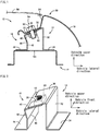
- FIG. 1 is a vertical sectional view of a fender panel support structure 10 for a vehicle according to an embodiment of the present invention.
- a pair of a first bracket 14 and a second bracket 16 are welded or otherwise integrally fixed to an upper member 12 of a radiator support or a body panel which is a vehicle body member.
- FIG 2 is a perspective view illustrating the first bracket 14 and the second bracket 16 alone, being disposed on the upper member 12.
- a plurality of pairs of the first bracket 14 and second bracket 16 thus configured are arranged at certain intervals along the vehicle length to support an upper portion 20 of the front fender panels 18 at a plurality of locations.
- a hood 56 is openably disposed between upper portions 20 of the right and left fender panels 18 to cover an engine compartment including the fender panel support structure 10.
- the first bracket 14 is located on the far side from the vehicle width center, and constituted of a metal plate material bent in a crank shape.
- the first bracket 14 includes a first upper wall 30, a first leg 32 extending downward continuously from the first upper wall 30, and a first flange 34 extending from the lower end of the first leg 32.
- the first bracket 14 is fixed to the upper member 12 on the first flange 34 in such an attitude that the first leg 32 extends generally vertically and generally in parallel with the vehicle length.
- the first flange 34 is formed by bending the first bracket 14 generally at a right angle such that the first flange 34 extends away from the vehicle width center.
- the first upper wall 30 is formed by bending the first bracket 14 such that the first upper wall 30 projects toward the vehicle width center.
- a U-shaped notch 36 is cut in the first upper wall 30, at a central portion in the vehicle length, extending from the edge on the far side from the vehicle width center.
- the upper member 12 is an elongated member extending along the vehicle length and having a hat-shaped cross section.
- the first flange 34 is laid on a generally horizontal raised flat portion 12s of the hat-shaped cross section so as to be in substantially close contact with the raised flat portion 12s, and is welded or otherwise integrally fixed to the raised flat portion 12s.
- the second bracket 16 is located on the near side from the vehicle width center, and constituted of a metal plate material bent in a crank shape.
- the second bracket 16 includes a second upper wall 40, a second leg 42 extending downward continuously from the second upper wall 40, and a second flange 44 extending from the lower end of the second leg 42.
- the second bracket 16 is fixed to the upper member 12 on the second flange 44 in such an attitude that the second leg 42 extends generally vertically and generally in parallel with the vehicle length.
- the second flange 44 is formed by bending the second bracket 16 generally orthogonally such that the second flange 44 extends toward the vehicle width center.
- the second upper wall 40 is formed by bending the second bracket 16 such that the second upper wall 40 projects away from the vehicle width center.
- the second flange 44 is laid on the raised flat portion 12s of the upper member 12 so as to be in substantially close contact with the raised flat portion 12s, and is welded or otherwise integrally fixed to the raised flat portion 12s.
- a bend 46 is located at an intermediate position of the height of the second leg 42. The bend 46 is such that the second leg 42 is slanting toward the vehicle width center as it nears the top. This allows the second upper wall 40 to be easily displaced toward the vehicle width center.
- the bend 46 serves as a deformable structure that allows the second upper wall 40 to be displaced toward the vehicle width center when an impact load is input from the fender panel 18 to the second upper wall 40.
- the second upper wall 40 is overlapped on the lower side of the first upper wall 30, in substantially close contact with the first upper wall 30, and includes a connector hole 48 at the central portion corresponding to the notch 36.
- a nut 50 is welded or otherwise integrated into the lower surface of the second upper wall 40, generally concentrically with the connector hole 48.
- the upper portion 20 of the fender panel 18 includes an attachment edge 22 that is laid on the upper surface of the first upper wall 30 in substantially close contact therewith.
- the upper portion 20 of the fender panel 18 also includes a rising section 24 that extends obliquely upward from the attachment edge 22 as it separates away from the vehicle width center.
- the bolt 52 is inserted through a connector hole 26 formed in the attachment edge 22 so that the fender panel 18 is integrally attached to the second upper wall 40 via the bolt 52.
- the first upper wall 30 Being interposed between the fender panel 18 and the second upper wall 40, the first upper wall 30 is clamped with the tightening force (or torque) of the bolt 52 and nut 50 and fixedly coupled by friction to the second upper wall 40.
- the second upper wall 40 together with the fender panel 18 is caused to be separated from the first upper wall 30 against the friction (or clamping force), traveling through the notch 36 toward the vehicle width center.
- the fender panel 18 includes the rising section 24 which extends obliquely upward as it separates away from the vehicle width center.
- a connector 54 comprises the bolt 52 and nut 50.
- the tightening force of the bolt 52 and nut 50 is predetermined as appropriate such that the first upper wall 30 and second upper wall 40 are coupled together with a certain clamping force and provide a desired support rigidity to support the fender panel 18 with, and such that when a certain impact load is input from the fender panel 18 to the second upper wall 40, the second upper wall 40 is displaced against the clamping force toward the vehicle width center and then separated from the first upper wall 30.
- the attachment edge 22, the first upper wall 30, and the second upper wall 40 described above are each shaped in a flat plate, and are inclined downward as they near the vehicle width center. Therefore, when a downward impact load F is input to the rising section 24 as illustrated in FIG 3(b) and the attachment edge 22 receives a force directed toward the vehicle width center, the attachment edge 22 and the second upper wall 40 are smoothly slid on the inclination toward the vehicle width center as indicated by the arrow A. In this way, the attachment edge 22 is lowered as well as traveling toward the vehicle width center. The amount of deformation (or vertical displacement of collapse) t of the fender panel 18 is thus increased to provide a better impact absorption.
- the rising section 24 extends obliquely upward as it separates away from the vehicle width center, the rising section 24 is deformed to increase an opening angle of the upper portion 20 of the fender panel 18 along with the descent of the attachment edge 22.
- the opening angle q2 after the deformation is larger than the opening angle q1 before the deformation. Therefore, the amount of deformation t is further increased to provide a better impact absorption.
- the first upper wall 30 and the second upper wall 40 are overlapped each other and connected together by the connector 54. Therefore, in the normal condition, the first bracket 14 and the second bracket 16 together provide a high support rigidity.
- the second upper wall 40 is separated from the first upper wall 30, overcoming the clamping force of the connector 54.
- the fender panel 18 thus supported by only the second bracket 16 reduces the support rigidity and provides a better impact absorption corresponding to the deformation of the second bracket 16.
- the second bracket 16 is fixed to the upper member 12 in such an attitude that the second leg 42 extends in parallel with the vehicle length, and the second upper wall 40 extends away from the vehicle width center and is overlapped on the first upper wall 30.
- the second upper wall 40 together with the fender panel 18 is displaced toward the vehicle width center and then separated from the first upper wall 30. This can reliably provide the desired impact absorption when an impact load is applied to the fender panel 16, in all conditions irrespective of deformation of the hood 56.
- both the first upper wall 30 and the second upper wall 40 are shaped in a flat plate, and are inclined downward as they near the vehicle width center. Therefore, when an impact load is input from the fender panel 18 to the second upper wall 40, the second upper wall 40 is smoothly slid on the inclination of the first upper wall 30 toward the vehicle width center. Consequently, this stably provides a desired impact absorption.
- the attachment edge 22 of the fender panel 18 is lowered as well as traveling toward the vehicle width center. Therefore, the amount of deformation t of the fender panel 18 itself is increased to obtain better impact absorption.
- first upper wall 30 defines the notch 36
- second upper wall 40 and the fender panel 18 define the connector holes 48 and 26, respectively
- the connector 54 comprises the bolt 52 inserted through the notch 36 and the connector holes 48 and 26 and the nut 50 screwed onto the bolt 52.
- the second upper wall 40 together with the fender panel 18 is displaced toward the vehicle width center with respect to the first upper wall 30 against the clamping force, with the bolt 52 traveling in the notch 36.
- the deformation of the second bracket 16 allows for the desired impact absorption.
- the clamping force can be easily adjusted by changing the tightening force of the bolt 52 and nut 50, and thereby the rigidity for supporting the fender panel 18, which corresponds to the clamping force, can be conveniently adjusted.
- the rising section 24 extends continuously from the attachment edge 22 of the fender panel 18.
- the attachment edge 22 receives a force directed toward the vehicle width center. Therefore, the second upper wall to which the attachment edge 22 is attached is smoothly displaced toward the vehicle width center, and desired impact absorption can be obtained stably.
- the rising section 24 is deformed such as to increase the opening angle of the upper portion 20 of the fender panel 18 and thus increase the deformation t of the fender panel 18 itself, resulting in a better impact absorption.
- the second leg 42 includes as a deformable structure the bend 46 such that the second leg 42 is slanting toward the vehicle width center as it nears the top. Therefore, the second upper wall 40 to which the fender panel 18 is attached is smoothly displaced toward the vehicle width center through the deformation of the second leg 42, which assuredly allows for the desired impact absorption.
- the impact absorption by the deformation of the second leg 42 can be adjusted in accordance with the position or the bend angle of the bend 46.
- the impact absorption bracket 100 comprising a single part including a pair of legs 102 that are laterally symmetric as illustrated in FIGS. 7 and 8(a)
- the impact absorption bracket 100 is buckled generally vertically downward with the pair of legs 102 collapsed generally symmetrically when an impact load F is input to the rising section 24 as illustrated in FIG 8(b) . Therefore, the attachment edge 22 is only displaced generally vertically downward, and the opening angles q1 and q2 of the rising section 24 are generally the same as each other, and therefore the deformation t of the fender panel 18 itself is so small that sufficient impact absorption cannot be obtained.
- the impact absorption and the support rigidity are determined by the impact absorption bracket 100 alone, and therefore it is difficult to appropriately adjust such properties.
- FIG 4 differs from the embodiment described above in the second bracket 60.
- a second leg 62 extending between the second upper wall 40 and the second flange 44 is shaped in a single flat plate that extends generally vertically, and includes a pair of grooves 64 and 66 that have a V-shaped section and that extend generally horizontally and parallel with the vehicle length as a deformable structure in place of the bend 46.
- the groove 64 is formed in a surface of the second leg 62 on the vehicle inner side at an intermediate position of the height.
- the groove 66 is formed in an inside surface of a bend between the second flange 44 and the second leg 62.
- the grooves 64 and 66 reduce the rigidity of the second leg 62, and allow the second upper wall 40 to be easily displaced toward the vehicle width center.
- the impact absorption by the deformation of the second leg 62 can be adjusted in accordance with the position, the depth, and the width of the grooves 64 and 66.
- the groove 64 may be formed in a surface of the second leg 62 on the vehicle outer side, and the groove 66 may be formed in an outside surface of the bend.
- FIG 5 shows an embodiment in which a second bracket 70 includes V-shaped notches (or cuts) 72 and 74 at side end edges on both sides of the second leg 62 in place of the grooves 64 and 66 described above. This may have substantially the same function and effect as those of the embodiment shown in FIG 4 .
- a first bracket 80 and a second bracket 82 according to an embodiment of FIG 6 differ from the first bracket 14 and the second bracket 16 of FIG 2 in that a first upper wall 84 and a second upper wall 86 extend generally horizontally, and in that the first upper wall 84 is provided with a pair of auxiliary legs 88 and 90 in addition to the first leg 32.
- the auxiliary legs 88 and 90 function as the first leg, and are each fixed to the upper member 12 on a flange extending from each lower end.
- the attachment edge 22 of the fender panel 18 extends generally horizontally as shown in FIG 8 .
- the attachment edge 22 is laid on the upper surface of the first upper wall 84 so as to be in substantially close contact therewith and is coupled to the first upper wall 84 and the second upper wall 86 by the connector 54.
- the fender panel 18, the first upper wall 84, and the second upper wall 86 are fixedly coupled by the connector 54.
- the fender panel 18 is supported with desired support rigidity.
- the first bracket 80 is provided with auxiliary legs 88 and 90. Therefore, high support rigidity can be secured easily.
- the auxiliary legs 88 and 90 may be included as necessary; they may be omitted.
- the first leg 32 may be omitted with the auxiliary legs 88 and 90 left included.
- the auxiliary legs 88 and 90 can be employed in addition to or in place of the first leg 32.
- the attachment edge 22 When a certain downward impact load F is input to the rising section 24 of the fender panel 18, the attachment edge 22 is subjected to a stress directed toward the vehicle width center. Therefore, the second upper wall 86 to which the attachment edge 22 is attached is displaced against the clamping force of the connector 54 toward the vehicle width center and then separated from the first upper wall 84. This provides the desired impact absorption corresponding to the deformation of the second bracket 82 or the fender panel 18 itself, as described in the embodiments above.
Landscapes
- Engineering & Computer Science (AREA)
- Chemical & Material Sciences (AREA)
- Combustion & Propulsion (AREA)
- Transportation (AREA)
- Mechanical Engineering (AREA)
- Body Structure For Vehicles (AREA)
Abstract
Description
- The present invention relates to a fender panel support structure for a vehicle, and in particular to a technique that appropriately allows desired impact absorption when an impact load is applied to a fender panel while securing the rigidity for supporting the fender panel.
- There has been known a fender panel support structure in a vehicle including an impact absorption bracket that includes an upper wall, a plurality of legs, and a plurality of flanges extending from the lower end of the plurality of legs. The bracket is fixed to a vehicle body member via the plurality of flanges and An upper portion of a fender panel is attached to the upper wall so that an impact load applied to the fender panel is absorbed through deformation of the plurality of legs. Patent Document 1 describes an example of such a support structure, in which the impact absorption bracket is constituted of a single part.
- Among such fender panel support structures for a vehicle, there is also a proposed structure that includes: (a) a first bracket that includes a first upper wall, a first leg extending downward continuously from the first upper wall, and a first flange extending from the lower end of the first leg; and (b) a second bracket that includes a second upper wall overlapped on the first upper wall, a second leg extending downward continuously from the second upper wall, and a second flange extending from the lower end of the second leg, (c) the first flange and the second flange being fixed to a vehicle body member, and an upper portion of a fender panel being attached to the first and second upper walls which are overlapped each other (see Patent Document 2).
-
- Patent Document 1: Japanese Patent Application Publication No.
2009-190565 - Patent Document 2: Japanese Patent Application Publication No.
2006-232085 - In the art described in Patent Document 1, however, the impact absorption bracket comprises a single part, making it difficult to maintain both the rigidity for supporting the fender panel and the absorption of impact load. In the art described in Patent Document 2, on the other hand, the first and second upper walls are overlapped each other and connected together, thereby producing a high support rigidity in normal conditions. When an impact load is applied, the second upper wall is lowered to be separated from the first upper wall, which reduces the rigidity for supporting the fender panel to obtain good impact absorption. In Patent Document 2, however, the second upper wall is pushed downward by a hood to be separated from the first upper wall. Therefore, when the impact is applied only to the fender panel, or depending on the mode of deformation of the hood, the second upper wall may not be separated from the first upper wall, resulting in a failure to appropriately provide the desired impact absorption.
- The present aspect of the invention has been made in view of the circumstances described above. This invention aims to reliably provide a desired impact absorption when an impact load is applied to a fender panel while securing the rigidity for supporting the fender panel.
- In order to achieve such an object, a first aspect of the invention provides a fender panel support structure for a vehicle, including: (a) a first bracket including a first upper wall, a first leg extending downward continuously from the first upper wall, and a first flange extending from a lower end of the first leg; and (b) a second bracket including a second upper wall overlapped on the first upper wall, a second leg extending downward continuously from the second upper wall, and a second flange extending from a lower end of the second leg, (c) the first flange and the second flange being fixed to a vehicle body member, and an upper portion of a fender panel being attached to the overlapped first and second upper walls. The fender panel support structure is characterized in that: (d) the second bracket is fixed to the vehicle body member in an attitude in which the second leg intersects a vehicle width, the second upper wall extends away from the vehicle width center and is overlapped on the first upper wall, and the fender panel is fixedly attached to the second upper wall; (e) the second leg includes a deformable structure allowing the second upper wall together with the fender panel to be displaced toward the vehicle width center when an impact load is input from the fender panel to the second upper wall; and (f) the fender panel support structure includes a connector coupling the first and second upper walls together with a certain clamping force such that when a certain impact load is input from the fender panel to the second upper wall, the second upper wall is displaced against the clamping force toward the vehicle width center and separated from the first upper wall.
- A second aspect of the invention provides the fender panel support structure for a vehicle according to the first aspect, characterized in that both the first and second upper walls are shaped in a flat plate and inclined downward as they near a vehicle width center so that the second upper wall is slid on the inclined first upper wall.
- A third aspect of the invention provides the fender panel support structure for a vehicle according to the first or second aspect, characterized in that: (a) the first upper wall defines a notch extending from its edge on the near side from the vehicle width center, and the second upper wall and the fender panel each define a connector hole; and (b) the connector comprises a bolt inserted through the notch and the connector holes, and a nut screwed onto the bolt, the bolt and nut being tightened each other to couple the first and second upper walls together with a certain clamping force and fixedly attach the fender panel to the second upper wall, and the notch allowing the second upper wall to be separated from the first upper wall until it is displaced toward the vehicle width center.
- A fourth aspect of the invention provides the fender panel support structure for a vehicle according to any one of the first to third aspects, characterized in that the upper portion of the fender panel includes an attachment edge attached to the second upper wall, and a rising section extending obliquely upward from the attachment edge as it separates away from the vehicle width center so that the attachment edge receives a force directed toward the vehicle width center when a downward impact load is input to the rising section.
- A fifth aspect of the invention provides the fender panel support structure for a vehicle according to any one of the first to fourth aspects, characterized in that a deformable structure in the second leg is a bend located in a middle of the height such that the second leg is slanting toward the vehicle width center as it nears the top.
- In the thus configured fender panel support structure for a vehicle, the first and second upper walls are overlapped each other and connected together by the connector. The first and second brackets together provide a high support rigidity in normal conditions. When a certain impact load is applied, on the other hand, the second upper wall is separated from the first upper wall, overcoming the clamping force of the connector. Therefore, the support rigidity is reduced with the fender panel supported by only the second bracket, and good impact absorption can be obtained corresponding to the deformation of the second bracket. In particular, the second bracket is fixed to a vehicle body member in such an attitude that the second leg intersects the vehicle width, and the second upper wall extends away from the vehicle width center and is overlapped on the first upper wall. When an impact load is input from the fender panel to the second upper wall, the second upper wall together with the fender panel is displaced toward the vehicle width center until it is separated from the first upper wall. This assuredly provides a desired impact absorption when an impact load is applied to the fender panel, in any situation whether the hood is deformed or not.
- In the second aspect of the invention, both the first and second upper walls are shaped in a flat plate, and are inclined downward as they near the vehicle width center. Therefore, when an impact load is input from the fender panel to the second upper wall, the second upper wall is smoothly slid on the inclination of the first upper wall toward the vehicle width center. This assuredly provides a desired impact absorption. In addition, the attachment edge of the fender panel is lowered as well as traveling toward the vehicle width center. This increases the deformation (or vertical displacement of collapse) of the fender panel itself to provide a better impact absorption.
- In the third aspect of the invention, the first upper wall defines the notch, the second upper wall and the fender panel define the connector holes, and the connector comprises the bolt inserted through the notch and the connector holes, and the nut screwed onto the bolt. When the bolt and nut are tightened each other with the fender panel and the first and second upper walls interposed between the bolt and nut, the first and second upper walls are coupled together with a certain clamping force to support the fender panel with desired support rigidity. In addition, when a certain impact load is input from the fender panel to the second upper wall via the bolt, the second upper wall together with the fender panel is displaced against the clamping force toward the vehicle width center with respect to the first upper wall, with the bolt traveling in the notch, to provide the desired impact absorption. In this case, the clamping force can be easily adjusted by changing the tightening force of the bolt and nut, and thereby the support rigidity, which corresponds to the clamping force, can be adjusted conveniently.
- In the fourth aspect of the invention, the rising section extends continuously from the attachment edge of the fender panel. When a downward impact load is input to the rising section, the attachment edge is subjected to a stress directed toward the vehicle width center. Therefore, the second upper wall to which the attachment edge is attached is smoothly displaced toward the vehicle width center, which assuredly allows for a desired impact absorption. In addition, the rising section is deformed such as to increase the opening angle of the upper portion of the fender panel which increases the deformation of the fender panel itself, resulting in a better impact absorption.
- In the fifth aspect of the invention, the second leg includes as a deformable structure the bend such that the second leg slanting toward the vehicle width center as it nears the top. The deformation of the second leg allows the second upper wall, where the fender panel is attached, to smoothly travel toward the vehicle width center, which assures a desired impact absorption. In addition, the impact absorption by the deformation of the second leg can be adjusted in accordance with the position or the bend angle of the bend.
-
-
FIG 1 is a vertical sectional view of a fender panel support structure for a vehicle according to an embodiment of the present invention. -
FIG 2 is a perspective view of a pair of brackets that constitute a main portion of the fender panel support structure ofFIG 1 . -
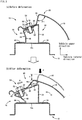
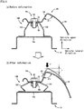
FIG 3 illustrates operation that occurs when an impact load F is input to the fender panel support structure ofFIG. 1 ,FIG 3 being a vertical sectional view corresponding toFIG 1 . -
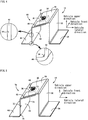
FIG 4 illustrates another embodiment of the present invention,FIG 4 being a perspective view of a pair of brackets corresponding toFIG 2 . -
FIG 5 illustrates still another embodiment of the present invention,FIG 5 being a perspective view of a pair of brackets corresponding toFIG 2 . -
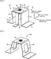
FIG 6 illustrates still another embodiment of the present invention,FIG 6 being a perspective view of a pair of brackets corresponding toFIG 2 . -
FIG 7 is a perspective view illustrating an impact absorption bracket in a fender panel support structure according to the prior art. -
FIG 8 illustrates operation that occurs when an impact load F is input to a fender panel support structure mainly constituted of the impact absorption bracket ofFIG 7 ,FIG 8 being a vertical sectional view corresponding toFIG 3 . - Examples of the vehicle body member to which the first and second flanges of the respective first and second brackets are fixed include an upper member of a radiator support or a body panel. The first and second flanges are integrally fixed to the vehicle body member, for example, by a welding process such as arc welding and spot welding. However, other fixing means such as screwing may also be employed.
- The deformable structure configured into the second leg of the second bracket allows for deformation of the second leg such that when a certain impact load is input from the fender panel to the second upper wall, the second upper wall is displaced toward the vehicle width center to be separated from the first upper wall to provide a desired impact absorption. A bend such that the second leg is slanting toward the vehicle width center as it nears the top, for example, is preferably used as the deformable structure. As an alternative to or in addition to the bend, a variety of implementations are possible, such as a groove with a V-shaped section that extends in the vehicle length, a notch in a side edge of the second leg in the vehicle length direction, a punched hole or slit (i.e. elongated through hole) in the second leg, a second bracket with a thickness smaller than that of the first bracket, or an appropriate combination thereof.
- The second leg of the second bracket is disposed in such an attitude that the second leg intersects the vehicle width. This is for the purpose of allowing the second upper wall to be easily displaced toward the vehicle width center when an impact load is applied to the fender panel. The second leg is desirably oriented to extend generally in parallel with the vehicle length, for example. However, it is not always necessary that the second leg should extend exactly in parallel with the vehicle length, and the second leg may be inclined to right or left.
- It is suitable that the overlapped first and second upper walls of the first and second brackets, respectively, are shaped in a flat plate that extends generally horizontally or is inclined downward as it nears the vehicle width center. The connector, which couples such a first upper wall and a second upper wall together with a certain clamping force (coupling strength), is suitably implemented by a bolt inserted through the notch defined in the first upper wall and a nut screwed onto the bolt, for example. However, the first and second upper walls may be coupled together using a coupling pin that is ruptured upon application of a certain impact load, or welded, bonded, or otherwise coupled together. The second upper wall and the fender panel are conveniently coupled together by the same bolt and nut that couple the first and second upper walls together. However, the second upper wall and the fender panel can be coupled together using another pair of bolt and nut separately from the one that couples the first and second upper walls. The second upper wall and the fender panel can also be welded, bonded or otherwise fixedly coupled together.
- Regarding the first and second upper walls, the second upper wall is overlapped on the lower side of the first upper wall, for example. However, the second upper wall may be overlapped on the upper side of the first upper wall. The first upper wall extends toward the vehicle width center and is overlapped on the second upper wall, for example. The first and second brackets are configured such that the first and second upper walls are coupled together to form a generally hat-shaped cross section as a whole. However, the direction of the first and second flanges is determined as appropriate. The first bracket may include two or more first legs to provide the desired support rigidity.
- When a certain impact load is applied from the fender panel to the second upper wall, the second upper wall is displaced toward the vehicle width center and then separated from the first upper wall. In this process the second bracket or the fender panel is deformed to provide desired impact absorption. It is not always necessary that the first bracket should be deformed. However, the first bracket may be deformed along with deformation of the second bracket or deformation of the fender panel.
- In the fourth aspect of the invention, the upper portion of the fender panel includes a rising section which extends obliquely upward from the attachment edge as it separates away from the vehicle width center. In implementations of the other aspects, a variety of forms such as a rising section extending upward and generally perpendicularly from the attachment edge can be used.
- Embodiments of the present invention will be described in detail below with reference to the drawings.
FIG. 1 is a vertical sectional view of a fenderpanel support structure 10 for a vehicle according to an embodiment of the present invention. A pair of afirst bracket 14 and asecond bracket 16 are welded or otherwise integrally fixed to anupper member 12 of a radiator support or a body panel which is a vehicle body member.FIG 2 is a perspective view illustrating thefirst bracket 14 and thesecond bracket 16 alone, being disposed on theupper member 12. A plurality of pairs of thefirst bracket 14 andsecond bracket 16 thus configured are arranged at certain intervals along the vehicle length to support anupper portion 20 of thefront fender panels 18 at a plurality of locations. Ahood 56 is openably disposed betweenupper portions 20 of the right and leftfender panels 18 to cover an engine compartment including the fenderpanel support structure 10. - The
first bracket 14 is located on the far side from the vehicle width center, and constituted of a metal plate material bent in a crank shape. Thefirst bracket 14 includes a firstupper wall 30, afirst leg 32 extending downward continuously from the firstupper wall 30, and afirst flange 34 extending from the lower end of thefirst leg 32. Thefirst bracket 14 is fixed to theupper member 12 on thefirst flange 34 in such an attitude that thefirst leg 32 extends generally vertically and generally in parallel with the vehicle length. Thefirst flange 34 is formed by bending thefirst bracket 14 generally at a right angle such that thefirst flange 34 extends away from the vehicle width center. The firstupper wall 30 is formed by bending thefirst bracket 14 such that the firstupper wall 30 projects toward the vehicle width center. AU-shaped notch 36 is cut in the firstupper wall 30, at a central portion in the vehicle length, extending from the edge on the far side from the vehicle width center. Theupper member 12 is an elongated member extending along the vehicle length and having a hat-shaped cross section. Thefirst flange 34 is laid on a generally horizontal raisedflat portion 12s of the hat-shaped cross section so as to be in substantially close contact with the raisedflat portion 12s, and is welded or otherwise integrally fixed to the raisedflat portion 12s. - The
second bracket 16 is located on the near side from the vehicle width center, and constituted of a metal plate material bent in a crank shape. Thesecond bracket 16 includes a secondupper wall 40, asecond leg 42 extending downward continuously from the secondupper wall 40, and asecond flange 44 extending from the lower end of thesecond leg 42. Thesecond bracket 16 is fixed to theupper member 12 on thesecond flange 44 in such an attitude that thesecond leg 42 extends generally vertically and generally in parallel with the vehicle length. Thesecond flange 44 is formed by bending thesecond bracket 16 generally orthogonally such that thesecond flange 44 extends toward the vehicle width center. The secondupper wall 40 is formed by bending thesecond bracket 16 such that the secondupper wall 40 projects away from the vehicle width center. Thesecond flange 44 is laid on the raisedflat portion 12s of theupper member 12 so as to be in substantially close contact with the raisedflat portion 12s, and is welded or otherwise integrally fixed to the raisedflat portion 12s. Abend 46 is located at an intermediate position of the height of thesecond leg 42. Thebend 46 is such that thesecond leg 42 is slanting toward the vehicle width center as it nears the top. This allows the secondupper wall 40 to be easily displaced toward the vehicle width center. Thebend 46 serves as a deformable structure that allows the secondupper wall 40 to be displaced toward the vehicle width center when an impact load is input from thefender panel 18 to the secondupper wall 40. - The second
upper wall 40 is overlapped on the lower side of the firstupper wall 30, in substantially close contact with the firstupper wall 30, and includes aconnector hole 48 at the central portion corresponding to thenotch 36. Anut 50 is welded or otherwise integrated into the lower surface of the secondupper wall 40, generally concentrically with theconnector hole 48. When abolt 52 is downwardly screwed through thenotch 36 andconnector hole 48 into thenut 50 and then tightened up, the firstupper wall 30 and secondupper wall 40 are coupled together with a certain clamping force. When coupled, thefirst bracket 14 and thesecond bracket 16 form a generally hat-shaped cross section, integrally fixed to theupper member 12, to support thefender panel 18 with a desired support rigidity. Theupper portion 20 of thefender panel 18 includes anattachment edge 22 that is laid on the upper surface of the firstupper wall 30 in substantially close contact therewith. Theupper portion 20 of thefender panel 18 also includes a risingsection 24 that extends obliquely upward from theattachment edge 22 as it separates away from the vehicle width center. Thebolt 52 is inserted through aconnector hole 26 formed in theattachment edge 22 so that thefender panel 18 is integrally attached to the secondupper wall 40 via thebolt 52. - Being interposed between the
fender panel 18 and the secondupper wall 40, the firstupper wall 30 is clamped with the tightening force (or torque) of thebolt 52 andnut 50 and fixedly coupled by friction to the secondupper wall 40. When a certain impact load is input from thefender panel 18 to the secondupper wall 40, the secondupper wall 40 together with thefender panel 18 is caused to be separated from the firstupper wall 30 against the friction (or clamping force), traveling through thenotch 36 toward the vehicle width center. Thefender panel 18 includes the risingsection 24 which extends obliquely upward as it separates away from the vehicle width center. Thus, when a downward impact load F is input to the risingsection 24 as illustrated inFIG 3(b) , theattachment edge 22 receives a force directed toward the vehicle width center. Theattachment edge 22 together with the secondupper wall 40 is separated from the firstupper wall 30, traveling toward the vehicle width center as indicated by the arrow A. Aconnector 54 comprises thebolt 52 andnut 50. The tightening force of thebolt 52 andnut 50 is predetermined as appropriate such that the firstupper wall 30 and secondupper wall 40 are coupled together with a certain clamping force and provide a desired support rigidity to support thefender panel 18 with, and such that when a certain impact load is input from thefender panel 18 to the secondupper wall 40, the secondupper wall 40 is displaced against the clamping force toward the vehicle width center and then separated from the firstupper wall 30. - The
attachment edge 22, the firstupper wall 30, and the secondupper wall 40 described above are each shaped in a flat plate, and are inclined downward as they near the vehicle width center. Therefore, when a downward impact load F is input to the risingsection 24 as illustrated inFIG 3(b) and theattachment edge 22 receives a force directed toward the vehicle width center, theattachment edge 22 and the secondupper wall 40 are smoothly slid on the inclination toward the vehicle width center as indicated by the arrow A. In this way, theattachment edge 22 is lowered as well as traveling toward the vehicle width center. The amount of deformation (or vertical displacement of collapse) t of thefender panel 18 is thus increased to provide a better impact absorption. In particular, since the risingsection 24 extends obliquely upward as it separates away from the vehicle width center, the risingsection 24 is deformed to increase an opening angle of theupper portion 20 of thefender panel 18 along with the descent of theattachment edge 22. Thus, the opening angle q2 after the deformation is larger than the opening angle q1 before the deformation. Therefore, the amount of deformation t is further increased to provide a better impact absorption. - In the thus configured fender
panel support structure 10, the firstupper wall 30 and the secondupper wall 40 are overlapped each other and connected together by theconnector 54. Therefore, in the normal condition, thefirst bracket 14 and thesecond bracket 16 together provide a high support rigidity. When a certain impact load F is input, on the other hand, the secondupper wall 40 is separated from the firstupper wall 30, overcoming the clamping force of theconnector 54. Thefender panel 18 thus supported by only thesecond bracket 16 reduces the support rigidity and provides a better impact absorption corresponding to the deformation of thesecond bracket 16. In particular, thesecond bracket 16 is fixed to theupper member 12 in such an attitude that thesecond leg 42 extends in parallel with the vehicle length, and the secondupper wall 40 extends away from the vehicle width center and is overlapped on the firstupper wall 30. When an impact load is transferred from thefender panel 18 to the secondupper wall 40, the secondupper wall 40 together with thefender panel 18 is displaced toward the vehicle width center and then separated from the firstupper wall 30. This can reliably provide the desired impact absorption when an impact load is applied to thefender panel 16, in all conditions irrespective of deformation of thehood 56. - In addition, both the first
upper wall 30 and the secondupper wall 40 are shaped in a flat plate, and are inclined downward as they near the vehicle width center. Therefore, when an impact load is input from thefender panel 18 to the secondupper wall 40, the secondupper wall 40 is smoothly slid on the inclination of the firstupper wall 30 toward the vehicle width center. Consequently, this stably provides a desired impact absorption. In addition, theattachment edge 22 of thefender panel 18 is lowered as well as traveling toward the vehicle width center. Therefore, the amount of deformation t of thefender panel 18 itself is increased to obtain better impact absorption. - In addition, the first
upper wall 30 defines thenotch 36, the secondupper wall 40 and thefender panel 18 define the connector holes 48 and 26, respectively, and theconnector 54 comprises thebolt 52 inserted through thenotch 36 and the connector holes 48 and 26 and thenut 50 screwed onto thebolt 52. When thebolt 52 andnut 50 are tightened each other with thefender panel 18, the firstupper wall 30, and the secondupper wall 40 interposed between thebolt 52 andnut 50, the firstupper wall 30 and the secondupper wall 40 are coupled together with a certain clamping force and provide a desired support rigidity to support thefender panel 18. In addition, when a certain impact load is input from thefender panel 18 via thebolt 52 to the secondupper wall 40, the secondupper wall 40 together with thefender panel 18 is displaced toward the vehicle width center with respect to the firstupper wall 30 against the clamping force, with thebolt 52 traveling in thenotch 36. The deformation of thesecond bracket 16 allows for the desired impact absorption. Thus, the clamping force can be easily adjusted by changing the tightening force of thebolt 52 andnut 50, and thereby the rigidity for supporting thefender panel 18, which corresponds to the clamping force, can be conveniently adjusted. - Moreover, the rising
section 24 extends continuously from theattachment edge 22 of thefender panel 18. When a downward impact load F is input to the risingsection 24, theattachment edge 22 receives a force directed toward the vehicle width center. Therefore, the second upper wall to which theattachment edge 22 is attached is smoothly displaced toward the vehicle width center, and desired impact absorption can be obtained stably. In addition, the risingsection 24 is deformed such as to increase the opening angle of theupper portion 20 of thefender panel 18 and thus increase the deformation t of thefender panel 18 itself, resulting in a better impact absorption. - Furthermore, the
second leg 42 includes as a deformable structure thebend 46 such that thesecond leg 42 is slanting toward the vehicle width center as it nears the top. Therefore, the secondupper wall 40 to which thefender panel 18 is attached is smoothly displaced toward the vehicle width center through the deformation of thesecond leg 42, which assuredly allows for the desired impact absorption. In addition, the impact absorption by the deformation of thesecond leg 42 can be adjusted in accordance with the position or the bend angle of thebend 46. - In contrast, in embodiments where the
fender panel 18 is supported using animpact absorption bracket 100 comprising a single part including a pair oflegs 102 that are laterally symmetric as illustrated inFIGS. 7 and8(a) , for example, theimpact absorption bracket 100 is buckled generally vertically downward with the pair oflegs 102 collapsed generally symmetrically when an impact load F is input to the risingsection 24 as illustrated inFIG 8(b) . Therefore, theattachment edge 22 is only displaced generally vertically downward, and the opening angles q1 and q2 of the risingsection 24 are generally the same as each other, and therefore the deformation t of thefender panel 18 itself is so small that sufficient impact absorption cannot be obtained. In addition, the impact absorption and the support rigidity are determined by theimpact absorption bracket 100 alone, and therefore it is difficult to appropriately adjust such properties. - Other embodiments of the present invention will now be described. Portions of the following embodiments that are substantially the same as those of the embodiment described above are given the same reference numerals to omit detailed description.
-
FIG 4 differs from the embodiment described above in thesecond bracket 60. In thesecond bracket 60, asecond leg 62 extending between the secondupper wall 40 and thesecond flange 44 is shaped in a single flat plate that extends generally vertically, and includes a pair ofgrooves bend 46. Thegroove 64 is formed in a surface of thesecond leg 62 on the vehicle inner side at an intermediate position of the height. Thegroove 66 is formed in an inside surface of a bend between thesecond flange 44 and thesecond leg 62. Thegrooves second leg 62, and allow the secondupper wall 40 to be easily displaced toward the vehicle width center. The impact absorption by the deformation of thesecond leg 62 can be adjusted in accordance with the position, the depth, and the width of thegrooves groove 64 may be formed in a surface of thesecond leg 62 on the vehicle outer side, and thegroove 66 may be formed in an outside surface of the bend. -
FIG 5 shows an embodiment in which asecond bracket 70 includes V-shaped notches (or cuts) 72 and 74 at side end edges on both sides of thesecond leg 62 in place of thegrooves FIG 4 . - A
first bracket 80 and asecond bracket 82 according to an embodiment ofFIG 6 differ from thefirst bracket 14 and thesecond bracket 16 ofFIG 2 in that a firstupper wall 84 and a secondupper wall 86 extend generally horizontally, and in that the firstupper wall 84 is provided with a pair ofauxiliary legs first leg 32. Theauxiliary legs upper member 12 on a flange extending from each lower end. In addition, theattachment edge 22 of thefender panel 18 extends generally horizontally as shown inFIG 8 . Theattachment edge 22 is laid on the upper surface of the firstupper wall 84 so as to be in substantially close contact therewith and is coupled to the firstupper wall 84 and the secondupper wall 86 by theconnector 54. - Also in the embodiment, the
fender panel 18, the firstupper wall 84, and the secondupper wall 86 are fixedly coupled by theconnector 54. Thus, thefender panel 18 is supported with desired support rigidity. In the embodiment, thefirst bracket 80 is provided withauxiliary legs auxiliary legs first leg 32 may be omitted with theauxiliary legs first bracket 14 according to the embodiments described above, theauxiliary legs first leg 32. - When a certain downward impact load F is input to the rising
section 24 of thefender panel 18, theattachment edge 22 is subjected to a stress directed toward the vehicle width center. Therefore, the secondupper wall 86 to which theattachment edge 22 is attached is displaced against the clamping force of theconnector 54 toward the vehicle width center and then separated from the firstupper wall 84. This provides the desired impact absorption corresponding to the deformation of thesecond bracket 82 or thefender panel 18 itself, as described in the embodiments above. - While embodiments of the present invention have been described in detail above with reference to the drawings, such embodiments are exemplary, and the present invention can be implemented with a variety of modifications and alterations on the basis of the knowledge of a person skilled in the art.
-
- 10
- Fender panel support structure
- 12
- Upper member (Vehicle body member)
- 14, 80
- First bracket
- 16, 60, 70, 82
- Second bracket
- 18
- Fender panel
- 20
- Upper portion
- 22
- Attachment edge
- 24
- Rising section
- 26
- Connector hole
- 30, 84
- First upper wall
- 32
- First leg
- 34
- First flange
- 36
- Notch
- 40, 86
- Second upper wall
- 42, 62
- Second leg
- 44
- Second flange
- 46
- Bend (Deformable structure)
- 48
- Connector hole
- 50
- Nut
- 52
- Bolt
- 54
- Connector
- 64, 66
- Groove (Deformable structure)
- 72, 74
- Notch (Deformable structure)
- 88, 90
- Auxiliary leg (First leg)
- F
- Impact load
Claims (5)
- A fender panel support structure for a vehicle, comprising:a first bracket including a first upper wall, a first leg extending downward continuously from the first upper wall, and a first flange extending from a lower end of the first leg; anda second bracket including a second upper wall overlapped on the first upper wall, a second leg extending downward continuously from the second upper wall, and a second flange extending from a lower end of the second leg,the first and second flanges being fixed to a vehicle body member, and an upper portion of a fender panel being attached to the overlapped first and second upper walls,the fender panel support structure being characterized in that:the second bracket is fixed to the vehicle body member in such an attitude that the second leg intersects a vehicle width, the second upper wall extends away from the vehicle width center and is overlapped on the first upper wall, and the fender panel is fixedly attached to the second upper wall;the second leg includes a deformable structure allowing the second upper wall together with the fender panel to be displaced toward the vehicle width center when an impact load is input from the fender panel to the second upper wall; andthe fender panel support structure includes a connector coupling the first and second upper walls together with a certain clamping force such that when a certain impact load is input from the fender panel to the second upper wall, the second upper wall is displaced against the clamping force toward the vehicle width center until it is separated from the first upper wall.
- The fender panel support structure for a vehicle according to claim 1, characterized in that
both the first and second upper walls are shaped in a flat plate and inclined downward as they near a vehicle width center so that the second upper wall is slid on the inclined first upper wall. - The fender panel support structure for a vehicle according to claim 1 or 2, characterized in that
the first upper wall defines a notch extending from its edge on the near side from the vehicle width center, and the second upper wall and the fender panel each define a connector hole, and
the connector comprising a bolt inserted through the notch and the connector holes, and a nut screwed onto the bolt, the bolt and the nut being tightened each other to couple the first and second upper walls together with a certain clamping force and fixedly attach the fender panel to the second upper wall, and the notch allowing the second upper wall to be displaced toward the vehicle width center until it is separated from the first upper wall. - The fender panel support structure for a vehicle according to any one of claims 1 to 3, characterized in that
the upper portion of the fender panel includes an attachment edge attached to the second upper wall, and a rising section extending obliquely upward from the attachment edge as it separates away from the vehicle width center so that the attachment edge receives a force directed toward the vehicle width center when a downward impact load is input to the rising section. - The fender panel support structure for a vehicle according to any one of claims 1 to 4, characterized in that
the deformable structure of the second leg is a bend located in a middle of the height of the second leg such that the second leg is slanting toward the vehicle width center as it nears the top.
Applications Claiming Priority (2)
| Application Number | Priority Date | Filing Date | Title |
|---|---|---|---|
| JP2013149810A JP5922064B2 (en) | 2013-07-18 | 2013-07-18 | Vehicle fender panel support structure |
| PCT/JP2014/059683 WO2015008511A1 (en) | 2013-07-18 | 2014-04-01 | Fender panel support structure for vehicle |
Publications (2)
| Publication Number | Publication Date |
|---|---|
| EP3023322A1 true EP3023322A1 (en) | 2016-05-25 |
| EP3023322A4 EP3023322A4 (en) | 2017-02-15 |
Family
ID=52345986
Family Applications (1)
| Application Number | Title | Priority Date | Filing Date |
|---|---|---|---|
| EP14826539.0A Withdrawn EP3023322A4 (en) | 2013-07-18 | 2014-04-01 | Fender panel support structure for vehicle |
Country Status (5)
| Country | Link |
|---|---|
| US (1) | US9446794B2 (en) |
| EP (1) | EP3023322A4 (en) |
| JP (1) | JP5922064B2 (en) |
| CN (1) | CN105473423B (en) |
| WO (1) | WO2015008511A1 (en) |
Families Citing this family (5)
| Publication number | Priority date | Publication date | Assignee | Title |
|---|---|---|---|---|
| DE102015005896A1 (en) | 2015-05-08 | 2016-11-10 | GM Global Technology Operations LLC (n. d. Gesetzen des Staates Delaware) | Support structure for supporting exterior trim components of a vehicle |
| US9902434B2 (en) * | 2015-07-30 | 2018-02-27 | Toyota Motor Engineering & Manufacturing North America, Inc. | Offset deforming fender attachment bracket |
| KR102896184B1 (en) * | 2020-10-05 | 2025-12-04 | 현대자동차 주식회사 | Fender mounting structure for vehicle |
| JP7509076B2 (en) * | 2021-04-23 | 2024-07-02 | トヨタ自動車株式会社 | Panel member mounting structure |
| US12491834B2 (en) * | 2023-08-15 | 2025-12-09 | JCsportline Co., Ltd. | Automobile fender |
Family Cites Families (12)
| Publication number | Priority date | Publication date | Assignee | Title |
|---|---|---|---|---|
| KR100387886B1 (en) | 2000-11-20 | 2003-06-18 | 현대자동차주식회사 | Fender panel impact absorption structure with walker protection function in car |
| JP3838125B2 (en) * | 2002-03-15 | 2006-10-25 | 日産自動車株式会社 | Fender structure |
| JP4123073B2 (en) * | 2003-06-26 | 2008-07-23 | トヨタ自動車株式会社 | Fender panel mounting structure |
| JP4396391B2 (en) * | 2004-05-21 | 2010-01-13 | 日産自動車株式会社 | Fender panel support structure |
| JP4631467B2 (en) * | 2005-02-24 | 2011-02-16 | 日産自動車株式会社 | Front fender upper end support structure |
| JP4207021B2 (en) * | 2005-06-01 | 2009-01-14 | トヨタ車体株式会社 | Vehicle fender panel support structure |
| JP4208005B2 (en) * | 2006-10-25 | 2009-01-14 | トヨタ自動車株式会社 | Fender panel mounting structure for vehicles |
| JP5217481B2 (en) | 2008-02-14 | 2013-06-19 | トヨタ車体株式会社 | Fender panel support bracket and body structure |
| US8182027B2 (en) * | 2009-06-15 | 2012-05-22 | Toyota Motor Engineering & Manufacturing North America, Inc. | Fender structure assemblies for vehicles |
| CN201907574U (en) * | 2010-12-14 | 2011-07-27 | 众泰控股集团有限公司 | Automobile fender installing support |
| JP5809942B2 (en) * | 2011-11-25 | 2015-11-11 | ダイハツ工業株式会社 | Automobile fender structure |
| JP5553819B2 (en) * | 2011-12-15 | 2014-07-16 | 豊田鉄工株式会社 | Vehicle fender panel support structure |
-
2013
- 2013-07-18 JP JP2013149810A patent/JP5922064B2/en not_active Expired - Fee Related
-
2014
- 2014-04-01 EP EP14826539.0A patent/EP3023322A4/en not_active Withdrawn
- 2014-04-01 WO PCT/JP2014/059683 patent/WO2015008511A1/en not_active Ceased
- 2014-04-01 CN CN201480045840.8A patent/CN105473423B/en not_active Expired - Fee Related
- 2014-04-01 US US14/906,201 patent/US9446794B2/en not_active Expired - Fee Related
Non-Patent Citations (1)
| Title |
|---|
| See references of WO2015008511A1 * |
Also Published As
| Publication number | Publication date |
|---|---|
| US9446794B2 (en) | 2016-09-20 |
| WO2015008511A1 (en) | 2015-01-22 |
| EP3023322A4 (en) | 2017-02-15 |
| CN105473423B (en) | 2017-06-13 |
| JP2015020574A (en) | 2015-02-02 |
| CN105473423A (en) | 2016-04-06 |
| JP5922064B2 (en) | 2016-05-24 |
| US20160159398A1 (en) | 2016-06-09 |
Similar Documents
| Publication | Publication Date | Title |
|---|---|---|
| US9855970B2 (en) | Vehicle front structure | |
| JP6118123B2 (en) | Vehicle frame structure | |
| US9446794B2 (en) | Fender panel support structure for vehicle | |
| US8662566B1 (en) | Multi extension front bumper beam | |
| US8919869B2 (en) | Vehicle rear body structure | |
| US20140117685A1 (en) | Vehicle-body structure of vehicle | |
| CN105121259A (en) | Structure for front part of vehicle | |
| CN101356077A (en) | Vehicle underrun protection device installation structure | |
| US20110260503A1 (en) | Polygonal cross-sectional frame, and rear vehicle body structure | |
| JP6278030B2 (en) | Vehicle front structure | |
| WO2014156065A1 (en) | Bumper joining structure and crush box | |
| CN100450854C (en) | Mounting structure of the support unit | |
| US20160068057A1 (en) | Vehicle front section structure | |
| CN103832480B (en) | The upper structure of rear vehicle | |
| JP5553819B2 (en) | Vehicle fender panel support structure | |
| JP2018154210A (en) | Underrun protector | |
| CN210852667U (en) | Vehicle body member, vehicle body member assembly, and vehicle body structure | |
| JP4207021B2 (en) | Vehicle fender panel support structure | |
| CN110588557A (en) | Radar support and vehicle | |
| JP2016117361A (en) | Vehicle front part structure | |
| JP6686688B2 (en) | Fender bracket structure | |
| JP2016064772A (en) | Underrun protector mounting structure and underrun protector bracket | |
| KR101760279B1 (en) | Connecting structure for door hinge of vehicles | |
| JP2016043851A (en) | Vehicle frame structure | |
| JP6866774B2 (en) | Rear underrun protector |
Legal Events
| Date | Code | Title | Description |
|---|---|---|---|
| PUAI | Public reference made under article 153(3) epc to a published international application that has entered the european phase |
Free format text: ORIGINAL CODE: 0009012 |
|
| 17P | Request for examination filed |
Effective date: 20160205 |
|
| AK | Designated contracting states |
Kind code of ref document: A1 Designated state(s): AL AT BE BG CH CY CZ DE DK EE ES FI FR GB GR HR HU IE IS IT LI LT LU LV MC MK MT NL NO PL PT RO RS SE SI SK SM TR |
|
| AX | Request for extension of the european patent |
Extension state: BA ME |
|
| DAX | Request for extension of the european patent (deleted) | ||
| A4 | Supplementary search report drawn up and despatched |
Effective date: 20170117 |
|
| RIC1 | Information provided on ipc code assigned before grant |
Ipc: B62D 25/16 20060101AFI20170111BHEP |
|
| GRAP | Despatch of communication of intention to grant a patent |
Free format text: ORIGINAL CODE: EPIDOSNIGR1 |
|
| INTG | Intention to grant announced |
Effective date: 20170918 |
|
| STAA | Information on the status of an ep patent application or granted ep patent |
Free format text: STATUS: THE APPLICATION IS DEEMED TO BE WITHDRAWN |
|
| 18D | Application deemed to be withdrawn |
Effective date: 20180130 |