EP3023319A1 - Steering device - Google Patents
Steering device Download PDFInfo
- Publication number
- EP3023319A1 EP3023319A1 EP14826317.1A EP14826317A EP3023319A1 EP 3023319 A1 EP3023319 A1 EP 3023319A1 EP 14826317 A EP14826317 A EP 14826317A EP 3023319 A1 EP3023319 A1 EP 3023319A1
- Authority
- EP
- European Patent Office
- Prior art keywords
- resin
- pin
- collar
- plate
- hole
- Prior art date
- Legal status (The legal status is an assumption and is not a legal conclusion. Google has not performed a legal analysis and makes no representation as to the accuracy of the status listed.)
- Granted
Links
Images





Classifications
-
- B—PERFORMING OPERATIONS; TRANSPORTING
- B62—LAND VEHICLES FOR TRAVELLING OTHERWISE THAN ON RAILS
- B62D—MOTOR VEHICLES; TRAILERS
- B62D1/00—Steering controls, i.e. means for initiating a change of direction of the vehicle
- B62D1/02—Steering controls, i.e. means for initiating a change of direction of the vehicle vehicle-mounted
- B62D1/16—Steering columns
- B62D1/18—Steering columns yieldable or adjustable, e.g. tiltable
- B62D1/19—Steering columns yieldable or adjustable, e.g. tiltable incorporating energy-absorbing arrangements, e.g. by being yieldable or collapsible
- B62D1/195—Yieldable supports for the steering column
-
- B—PERFORMING OPERATIONS; TRANSPORTING
- B62—LAND VEHICLES FOR TRAVELLING OTHERWISE THAN ON RAILS
- B62D—MOTOR VEHICLES; TRAILERS
- B62D1/00—Steering controls, i.e. means for initiating a change of direction of the vehicle
- B62D1/02—Steering controls, i.e. means for initiating a change of direction of the vehicle vehicle-mounted
- B62D1/16—Steering columns
- B62D1/18—Steering columns yieldable or adjustable, e.g. tiltable
- B62D1/187—Steering columns yieldable or adjustable, e.g. tiltable with tilt adjustment; with tilt and axial adjustment
- B62D1/189—Steering columns yieldable or adjustable, e.g. tiltable with tilt adjustment; with tilt and axial adjustment the entire column being tiltable as a unit
Definitions
- the present invention relates to a steering device.
- a secondary collision in which the driver collides with a steering wheel occurs.
- various structures in which a part of a steering column releases from the vehicle body, and is moved in the direction of the column shaft have been proposed.
- a pair of engaging cutouts which extend parallel to the direction of a column shaft are disposed in a vehicle body-side bracket fixed to the vehicle body.
- a column-side bracket is supported through a pair of engaging capsules which are held by a plurality of engaging pins, by the engaging cutouts respectively.
- the engaging capsules are coupled and fixed to the column-side bracket through bolts which are passed through the engaging cutouts, respectively.
- the plurality of engaging pins holding the engaging capsules are broken, whereby the engaging capsules are caused to release from the corresponding engaging cutouts, and the bolts, the engaging capsules, and the column bracket are caused to co-move with one another in the column shaft direction.
- Patent Reference 1 JP-A-2012-121538
- the inventors of the present application firstly considered that a slide plate which closes the upper side of a resin pin, and which, in a secondary collision, is moved in the movement direction of the column is disposed, and an elastic repulsion force is applied to the slide plate by an axial elastic projection disposed on the resin pin.
- a resin-pin visual check hole for visually checking a resin pin is disposed in a slide plate.
- the invention provides a steering device comprising: a stationary bracket which is fixed to a vehicle body-side member, and which includes a first plate in which a first resin-pin passing hole, and a first bolt passing hole configured by a long hole that extends in a column movement direction in a secondary collision are formed; a movable jacket which is configured to rotatably support a steering shaft in which a steering member is coupled to one end; a movable bracket which is configured to support the movable jacket in a manner that, in a secondary collision, the movable bracket is moved together with the movable jacket in the column movement direction, and which includes a second plate that is opposed to a lower surface of the first plate, the second plate in which a second resin-pin passing hole and a second bolt passing hole are formed; a suspension mechanism which includes: a slide plate in which a third bolt passing hole and a resin-pin visual check hole are formed along an upper surface of the first plate; and a suspension bolt which is passed sequentially through the third
- the axial elastic projection which directly or indirectly urges the slide plate is disposed at a position avoiding the range where, in a secondary collision, the resin-pin visual check hole passes in the column movement direction. Therefore, it is possible to, in a secondary collision, suppress the axial elastic projection of the resin pin from being caught in the resin-pin visual check hole. Consequently, an influence due to catching on the releasing load (increase of the releasing load) can be suppressed.
- the resin pin may include: a shaft portion which is passed through the collar; and a head flange which is coupled to one end of the shaft portion, the head flange may have: a first surface which is opposed to the slide plate; and a second surface which is opposed to an end surface of the collar, the elastic projection may be placed at a position avoiding the resin-pin visual check hole in the first surface of the head flange, and a rotation restricting convex portion which is disposed in at least one of the second surface of the head flange and the end surface of the collar may be fitted to a rotation restricting concave portion which is disposed on the other surface, thereby restricting relative rotation of the resin pin and the collar.
- the resin pin may include: a shaft portion which is passed through the collar; and a head flange which is coupled to one end of the shaft portion, an inner circumference of the first resin-pin passing hole may include a flat portion which is engaged with a flat portion disposed on an outer circumference of the head flange, thereby restricting rotation of the resin pin, the head flange may have: a first surface which is opposed to the slide plate; and a second surface which is opposed to an end surface of the collar, and the elastic projection may be placed at a position avoiding the resin-pin visual check hole in the first surface of the head flange.
- the resin pin may include: a shaft portion which is passed through the collar; and a head flange which is coupled to one end of the shaft portion, the head flange may have: a first surface which is opposed to the slide plate; and a second surface which is opposed to an end surface of the collar, and the elastic projection may be disposed on the second surface of the head flange.
- the head flange of the resin pin has the first surface which is opposed to the slide plate, and the second surface which is opposed to the collar, and the axial elastic projection is not disposed on the first surface, but disposed on the second surface.
- the catch of the axial elastic projection in the resin-pin visual check hole can never happen.
- the collar may include: a first collar which is placed in the first resin-pin passing hole, and which is press-fitted to the resin pin; and a second collar which is placed in the second resin-pin passing hole, and which is loose-fitted to the resin pin, and the elastic projection may be disposed on at least one of opposing surfaces the first collar and the second collar.
- the axial elastic projection is disposed on at least one of the opposing surfaces the first collar and the second collar. Therefore, the catch of the elastic projection in the resin-pin visual check hole can never happen.
- the resin-pin visual check hole may include a collar visual check region through which a part of the collar can be visually checked.
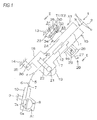
- Fig. 1 is a diagrammatic view schematically showing the configuration of a steering device of a first embodiment of the invention.
- the steering device 1 includes: a steering shaft 3 which is coupled to a steering member 2 such as a steering wheel; an intermediate shaft 5 which is coupled to the steering shaft 3 through a universal joint 4; a pinion shaft 7 which is coupled to the intermediate shaft 5 through a universal joint 6; and a rack shaft 8 functioning as a steering shaft having a rack 8a which meshes with a pinion 7a disposed in the vicinity of an end portion of the pinion shaft 7.
- a steering mechanism A1 is configured by a rack and pinion mechanism including the pinion shaft 7 and the rack shaft 8.
- the rack shaft 8 is supported by a housing 10 fixed to a vehicle body-side member 9, so as to be movable in the axial direction (direction perpendicular to the sheet) extending along the lateral direction of a vehicle. End portions of the rack shaft 8 are not illustrated, but are connected to respective steered wheels through a corresponding tie rod and a corresponding knuckle arm.
- the steering shaft 3 has an upper shaft 11 and lower shaft 12 which are connected to each other by using, for example, a spline coupling so as to be co-rotatable and axially relatively movable.
- the steering shaft 3 is rotatably supported by a steering column 15 fixed to vehicle body-side members 13, 14, through a bearing which is not shown.
- the steering column 15 includes a tubular upper jacket 16 (movable jacket), and tubular lower jacket 17 which are fitted to each other so as to be axially relatively movable, and a housing 18 which is connected to the axial lower end of the lower jacket 17.
- a reduction mechanism 20 which reduces the power of an electric motor 19 for assisting the steering, and which transmits the reduced power to the lower shaft 12 is housed in the housing 18.
- the reduction mechanism 20 has a driving gear 21 which is co-rotatably coupled to a rotation shaft (not shown) of the electric motor 19, and a driven gear 22 which meshes with the driving gear 21 to co-rotate with the lower shaft 12.
- the invention may be applied also to a manual steering device.
- the embodiment will be described with reference to an example in which the steering device 1 is tilt-adjustable, the invention may be applied also to a steering device which is not provided with a tilt adjusting function, or that which is tilt-adjustable and telescopically adjustable.
- the steering device 1 includes the pair of suspension mechanisms T1, T2 in which the upper jacket 16 is suspended by the stationary bracket 23 through the tilt bracket 24 functioning as the movable bracket.
- the tilt bracket 24 functioning as the movable bracket is suspended from the stationary bracket 23 fixed to the vehicle body-side member 13, through suspension bolts 25 functioning as the suspension shafts of the pair of suspension mechanisms T1, T2.
- a column bracket 26 is fixed to the upper jacket 16 of the steering column 15.
- the steering device 1 includes the locking mechanism 29 which, in accordance with an operation performed on an operation lever 27, the position of the column bracket 26 which has undergone the tilt adjustment (therefore, the positions of the upper jacket 16 and the steering member 2) is locked or unlocked through the tilt bracket 24 by using a fastening shaft 28.
- the tilt bracket 24 includes a pair of side plates 41.
- the column bracket 26 has a groove-like shape including a pair of side plates 71 which are opposed to the pair of side plates 41 of the tilt bracket 24, respectively, and a coupling plate 72 through which the lower ends of the pair of side plates 71 are coupled to each other.
- the fastening shaft 28 is configured by a bolt which is passed through the side plates 41, 71 of the tilt bracket 24 and the column bracket 26.
- a nut 73 screwed with the fastening shaft 28 is rotated by an operation of rotating the operation lever 27, the side plates 41, 71 are fastened together between the head of the bolt functioning as the fastening shaft 28 and the nut 73, thereby locking the side plates 41, 71. Therefore, the position of the steering member 2 after the tilt adjustment is locked, and the tilt locking is accomplished.
- the steering device 1 includes a coupling/decoupling mechanism R1 through which a first plate 30 of the stationary bracket 23 and a second plate 32 of the tilt bracket 24 are coupled to each other, and which, in a second collision, causes the second plate 32 to release from a predetermined position (position shown in Fig. 9 ) of the first plate 30 in a column movement direction X1 as shown in Fig. 10 .
- the coupling/decoupling mechanism R1 is placed between the pair of suspension mechanisms T1, T2 (i.e., between a pair of first bolt passing holes 31 which will be described later, and which are in the first plate 30 of the stationary bracket 23) with respect to a direction Y1 that is perpendicular to the column movement direction X1.
- the coupling/decoupling mechanism R1 is placed in the middle position between the pair of first bolt passing holes 31 (i.e., between the pair of suspension bolts 25) with respect to the direction Y1 that is perpendicular to the column movement direction X1.
- the stationary bracket 23 includes the first plate 30 which is parallel to the column movement direction X1 (corresponding to the axial direction of the steering shaft 3) in a secondary collision.
- the first plate 30 which is parallel to the column movement direction X1 (corresponding to the axial direction of the steering shaft 3) in a secondary collision.
- the first bolt passing holes 31 for the suspension mechanisms T1, T2 and configured by long holes extending parallel to the column movement direction X1 are formed.
- the tilt bracket 24 (movable bracket) includes the second plate 32 which is opposed to the first plate 30.
- second bolt passing holes 33 opposed to parts of the first bolt passing holes 31, and for the suspension mechanisms T1, T2 are formed.
- the suspension bolts 25 are configured by bolts which are passed through the first bolt passing holes 31 of the first plate 30, and the second bolt passing holes 33 of the second plate 32, and which are screwed with nuts 34.
- the suspension bolts 25 which cooperate with the nuts 34 to couple the first plate 30 and the second plate 32 with each other suspend the upper jacket 16 (movable jacket) through the tilt bracket 24 (movable bracket) and the column bracket 26.
- the suspension bolts 25 are movable in the column movement direction X1 along the first bolt passing holes 31 together with the tilt bracket 24 (movable bracket), the column bracket 26, and the upper jacket 16.
- a lower bracket 35 which is fixed to the vehicle body-side member 14 supports a tilt center shaft 36 functioning as a pivot shaft.
- the tilt center shaft 36 supports the lower jacket 17 through the housing 18 of the steering column 15, so as to be swingable about the tilt center shaft 36.
- each of the suspension mechanisms T1, T2 is configured by the suspension bolt 25, a plate spring 42 formed by, for example, a disc spring, the nut 34, and the like.
- the coupling/decoupling mechanism R1 is configured by a resin pin 61 which is to be sheared in a secondary collision, and a collar 62 which is fitted to a part in the axial direction of the resin pin 61, and in which the outer circumference is formed into a laterally elongated shape such as an oblong circular shape.
- a metal such as iron may be used, or a resin, ceramic, or the like which is higher in hardness than the resin pin 61 may be used.
- the resin pin 61 may be formed by polyacetal resin (POM), and the collar 62 may be formed by polyamide resin (PA) which is higher in hardness than polyacetal resin.
- the stationary bracket 23 includes a pair of side plates 37 which are downward extended from a pair of side edges of the first plate 30, and a pair of attachment plates 38 which are extended outwardly and laterally from the pair of side plates 37, respectively.
- the stationary bracket 23 is formed by, for example, sheet metal work.
- the attachment plates 38 are fixed to the vehicle body-side member 13 by fixing bolts 40 (see Fig. 4 ) which are passed through screw passing holes 39 (see Figs. 3 and 4 ) disposed in the attachment plates 38, respectively. As shown in Fig. 1 , therefore, the stationary bracket 23 is fixed to the vehicle body-side member 13.
- the first bolt passing holes 31 are pairingly formed correspondingly with the pair of suspension bolts 25.
- the pair of first bolt passing holes 31 extend parallel to the column movement direction X1 in a secondary collision, and are separated from each other in the direction Y1 that is perpendicular to the column movement direction X1.
- the tilt bracket 24 (movable bracket) is formed by, for example, sheet metal work.
- the tilt bracket 24 includes the second plate 32, and a pair of side plates 41 which are downward extended from a pair of side edges of the second plate 32, and is formed into a groove-like shape.
- portions where the second plate 32 is coupled to the side plates 41 may be formed into an arcuate shape.
- the second bolt passing holes 33 are pairingly disposed correspondingly with the pair of suspension bolts 25.
- Each of the suspension bolts 25 is sequentially passed through the annular plate spring 42 formed by, for example, a disc spring, a corresponding third bolt passing hole 44 of a slide plate 43, the corresponding first bolt passing hole 31 of the first plate 30, and the corresponding second bolt passing hole 33 of the second plate 32, and then screwed with the nut 34. According to the configuration, the suspension bolts 25 suspend the tilt bracket 24.
- the slide plate 43 is configured by a long plate which extends in the direction Y1 that is perpendicular to the column movement direction X1, and, as shown in Fig. 2 , interposed between the plate springs 42 and the upper surface 30a of the first plate 30.
- the slide plate 43 at least the surface on the side of the first plate 30 is configured by a low-friction material such as a fluorine resin.
- the whole of the slide plate 43 may be configured by a low-friction material, or the surface of the slide plate 43 on the side of the first plate 30 may be covered with a low-friction material.
- a first interposed plate 45 and second interposed plate 46 which, in a secondary collision, reduce the sliding resistance in the movement of the second plate 32 in the column movement direction X1 with respect to the first plate 30 are interposed between the first plate 30 and the second plate 32.
- the first interposed plate 45 constitutes a groove-like unit 45U which is engaged with a first end portion 321 that is an end portion in the column movement direction X1 of the second plate 32.
- the unit 45U includes: the first interposed plate 45 which extends along the upper surface 32a of the second plate 32 and the lower surface 30b of the first plate 30; an opposing plate 47 which is opposed to the first interposed plate 45, and which extends along the lower surface 32b of the second plate 32; and a coupling plate 48 which couples the first interposed plate 45 with the opposing plate 47, and which butts against the edge in the column movement direction X1 of the second plate 32.
- the first interposed plate 45 at least the surface on the side of the first plate 30 is configured by a low-friction material such as a fluorine resin.
- a low-friction material such as a fluorine resin.
- the first interposed plate 45 or the unit 45U may be configured by a low-friction material, or the surface of the first interposed plate 45 on the side of the first plate 30 may be covered with a low-friction material.
- the second interposed plate 46 constitutes a unit 46U which is engaged with a second end portion 302 that is an end portion of the first plate 30 opposite to the column movement direction X1, and a second end portion 322 that is an end portion of the second plate 32 opposite to the column movement direction X1.
- the unit 46U includes the second interposed plate 46 which extends along the upper surface 32a of the second plate 32 and the lower surface 30b of the first plate 30, and an opposing plate 49 which is opposed to the second interposed plate 46, and which extends along the upper surface 30a of the first plate 30.
- the unit 46U further includes a coupling plate 50 which couples the second interposed plate 46 with the opposing plate 49, and which butts against the edge of the first plate 30 opposed to the column movement direction X1, and an engaging portion 51 which is to be hookingly engaged with the second end portion 322 of the second plate 32, and which has, for example, a hook-like shape.
- the second interposed plate 46 at least the surface on the side of the second plate 32 is formed by a low-friction material such as a fluorine resin.
- a low-friction material such as a fluorine resin.
- the second interposed plate 46 or the unit 46U may be formed by a low-friction material, or the surface of the second interposed plate 46 on the side of the second plate 32 may be covered with a low-friction material.
- each of the suspension bolts 25 includes: a head portion 52; a large-diameter portion 53 which is continuous to the head portion 52, and which is smaller in diameter than the head portion 52; a small-diameter portion 54 which is continuous to the large-diameter portion 53, and which is smaller in diameter than the large-diameter portion 53; a step portion 55 which is formed between the large-diameter portion 53 and the small-diameter portion 54; and a threaded portion 56 which is disposed in the small-diameter portion 54.
- a tool engagement part 57 which has, for example, a hexagonal hole shape is disposed in the head portion 52.
- the large-diameter portion 53 is passed through the annular plate spring 42, the third bolt passing hole 44 of the slide plate 43, and the first bolt passing hole 31 of the first plate 30.
- the step portion 55 butts against the upper surface 32a of the second plate 32 to be received by the upper surface 32a.
- the second plate 32 is pressingly held between the step portion 55 and the nut 34, and the suspension bolts 25 and the second plate 32 are fixed.
- the distance H1 (corresponding to the shaft length of the large-diameter portion 53) between the head portion 52 and the step portion 55 is made larger than the total of the thickness of the first interposed plate 45 (or that of the second interposed plate 46) which is interposed between the first plate 30 and the second plate 32, that of the first plate 30, that of the slide plate 43 which extends along the upper surface 30a of the first plate 30, and that of the plate springs 42 in the most compressed state. Therefore, the plate springs 42 elastically urges the first plate 30 toward the second plate 32 through the slide plate 43.
- the resin pin 61 of the first plate 30, and for the coupling/decoupling mechanism R1 is placed in the middle position between the first bolt passing holes 31 for the suspension mechanisms T1, T2 with respect to the direction Y1 that is perpendicular to the column movement direction X1. That is, the resin pin 61 is placed in the middle position between the pair of suspension bolts 25 with respect to the direction Y1 that is perpendicular to the column movement direction X1.
- the first resin-pin passing hole 66 of the first plate 30, and for the coupling/decoupling mechanism R1 is formed into a laterally long hole which extends in the direction Y1 that is perpendicular to the column movement direction X1. Therefore, gaps S1, S2 are disposed between the outer circumference of the collar 62 and the inner circumference of the first resin-pin passing hole 66 with respect to the direction Y1 that is perpendicular to the column movement direction X1.
- the resin pin 61 of the coupling/decoupling mechanism R1 includes a head flange 63 which has, for example, a circular section, and a columnar shaft portion 64 which is smaller in diameter than the head flange 63.
- the slide plate 43 is placed so as to cover the upper side of the head flange 63 of the resin pin 61, thereby preventing the resin pin 61 from upwardly slipping off.
- a resin-pin visual check hole 65 which is smaller than the outer diameter of the head flange 63 of the resin pin 61 is formed so as to be opposed to the head portion 63.
- the head flange 63 of the resin pin 61 and most of the collar 62 are inserted into the first resin-pin passing hole 66 of the first plate 30 of the stationary bracket 23, and for the coupling/decoupling mechanism R1.
- a part of the collar 62 projects from the first resin-pin passing hole 66.
- a part which projects from the collar 62 is passed through a second resin-pin passing hole 67 of the second plate 32 of the tilt bracket 24 (movable bracket), and for the coupling/decoupling mechanism R1.
- the head flange 63 has a first surface 631 which is opposed to the slide plate 43, and a second surface 632 which is opposed to a first end surface 621 (upper end surface) of the collar 62.
- a plurality of elastic projections 81 that project in the axial direction of the resin pin 61 are placed at positions which, in an initial attached state, do not interfere with the resin-pin visual check hole 65 of the slide plate 43 in a plan view, and which avoid a range where, in a secondary collision, the resin-pin visual check hole 65 is passed in the column movement direction X1.
- the plurality of elastic projections 81 are annularly arranged so that they are arranged at regular intervals on a circumference surrounding the resin-pin visual check hole 65 in a plan view, and the phase is at a position which avoids a range where, in a secondary collision, the resin-pin visual check hole 65 is passed in the column movement direction X1.
- the plurality of elastic projections 81 are in contact with the lower surface of the slide plate 43 in a state where the projections are elastically compressed, and directly press and urge the slide plate 43 by means of an elastic repulsion force.
- At least one rotation restricting convex portion 82 which projects toward the first end surface 621 of the collar 62 is disposed on the second surface 632 of the head flange 63.
- a rotation restricting concave portion 83 which is to engage with the rotation restricting convex portion 82 is disposed on the first end surface 621 of the collar 62.
- the outer circumference of the collar 62 is formed into a laterally elongated shape such as an oblong circular shape which extends in the direction Y1 that is perpendicular to the column movement direction X1, and fitted to the first resin-pin passing hole 66 which is in the first plate 30, and which is a laterally long hole which extends in the direction Y1 that is perpendicular to the column movement direction X1. Therefore, rotation of the collar 62 is restricted by the first resin-pin passing hole 66. Namely, the first resin-pin passing hole 66 restricts rotation of the resin pin 61 about the center axis of the resin pin 61 through the collar 62.
- the shaft portion 64 of the resin pin 61 is inserted into a center hole 623 of the collar 62.
- the outer diameter of the collar 62 is made larger than that of the head flange 63 of the resin pin 61.
- the first axial end surface 621 of the collar 62 butts against the head flange 63 of the resin pin 61, and a second axial end surface 622 of the collar 62 is received by the upper surface 32a of the second plate 32 which is the member suspended by the suspension mechanisms T1, T2, whereby the resin pin 61 and the metal collar 62 are prevented from slipping off to the lower side of the second plate 32.
- the shaft portion 64 of the resin pin 61 is sheared by displacement between the matching surfaces of the second end surface 622 of the collar 62 and the second plate 32 due to the movement of the second plate 32 with respect to the first plate 30. Namely, a part 641 of the shaft portion 64 separates from the remaining part.
- a shearing edge configured by the inner peripheral edge of the second end surface 622 of the collar 62 has an arcuate shape, and also a shearing edge configured by the edge portion of the second resin-pin passing hole 67 of the second plate 32 has an arcuate shape.
- the axial elastic projections 81 which applies the elastic repulsion force (pressing and urging force) to the slide plate 43 are disposed at the positions which, in the initial attached state, do not interfere with the resin-pin visual check hole 65, and which avoid a range where, in a secondary collision, the resin-pin visual check hole 65 is passed in the column movement direction X1. Therefore, it is possible to, in a secondary collision, suppress the axial elastic projections 81 of the resin pin 61 from being caught in the resin-pin visual check hole 65. Consequently, an influence due to catching in a secondary collision between the axial elastic projections 81 of the resin pin 61 and the resin-pin visual check hole 65, on the releasing load (increase of the releasing load) can be suppressed.
- the inner circumference of the first resin-pin passing hole 66, and outer circumference of the collar 62 which are fitted to each other are formed into a laterally long shape which extends in the direction that is perpendicular to the column movement direction X1, and therefore rotation of the collar 62 is restricted by the first resin-pin passing hole 66.
- rotation of the resin pin 61 is restricted by the collar 62. In a secondary collision, therefore, it is possible to surely prevent the resin pin 61 from rotating about the center axis to cause the elastic projection 81 to be caught in the resin-pin visual check hole 65.
- the attitude of the resin pin 61 in a secondary collision can be stabilized as far as possible.
- the rotation restricting convex portion may be disposed on the first end surface 621 of the collar 62, and the rotation restricting concave portion may be disposed on the second surface 632 of the head flange 63.
- Fig. 11 is an exploded perspective view of a resin pin 61A and collar 62A in a coupling/decoupling mechanism R1A in a second embodiment of the invention.
- Fig. 12 is a sectional view of a coupled state of the first plate 30 and second plate 32 in the second embodiment, and shows a section in the anteroposterior direction (column movement direction X1) including the axis of the resin pin 61A.
- the resin pin 61A includes a columnar shaft portion 64A which is passed through a center hole 623A of an annular collar 62A, and a head flange 63A which is coupled to one end of the shaft portion 64A.
- the head flange 63A has a first surface 63A1 which is opposed to the slide plate 43 as shown in Fig. 12 , and an annular second surface 63A2 which is opposed to a first end surface 62A1 of the collar 62A.
- a plurality of axial elastic projections 81A which are annularly arranged at regular intervals in the circumferential direction on a circumference surrounding the shaft portion 64A are formed on second surface 63A2 of the head flange 63A.
- the elastic projections 81A are contacted with the first end surface 62A1 of the collar 62A in a state where the projections are elastically compressed, and give an elastic repulsion force to the collar 62A.
- the first surface 63A1 of the head flange 63 of the resin pin 61 is urged toward the slide plate 43, and a second end surface 62A2 of the collar 62A is urged toward the upper surface 32a of the second plate 32.
- the head flange 63A and most of the collar 62A are inserted into the first resin-pin passing hole 66 of the first plate 30.
- a part of the shaft portion 64A projects from the collar 62A, and is inserted into the second resin-pin passing hole 67 of the second plate 32.
- the collar 62A is formed by a resin, ceramic, metal, or the like which is higher in hardness than the resin pin 61A.
- the resin pin 61A may be formed by polyacetal resin (POM), and the collar 62A may be formed by polyamide resin (PA) which is higher in hardness than polyacetal resin.
- POM polyacetal resin
- PA polyamide resin
- the head flange 63A of the resin pin 61A has the first surface 63A1 which is opposed to the slide plate 43, and the second surface 63A2 which is opposed to the collar 62A, and the axial elastic projections 81A are disposed not on the first surface 63A1 but on the second surface 63A2.
- the elastic projections 81A are in contact with the first surface 62A1 of the collar 62A in which the second surface 62A2 is received by the second plate 32 (suspended member), in a state where the projections are elastically compressed.
- the elastic projections 81A indirectly apply the pressing and urging force (elastic repulsion force) to the slide plate 43 through the first surface 63A1 of the head flange 63A of the resin pin 61A.
- the catch of the axial elastic projections 81A disposed on the second surface 63A2 which is not opposed to the slide plate 43, in the resin-pin visual check hole 65 can never happen. Therefore, an influence due to the above-described catch on the releasing load (increase of the releasing load) can be suppressed.
- the axial elastic projections disposed on the first end surface 62A1 of the collar 62A may butt against the second surface 63A2 of the head flange 63A of the resin pin 61A.
- Fig. 13 is an exploded perspective view of a resin pin 90 and two-step collar (first collar 91 and second collar 92) in a coupling/decoupling mechanism R1B in a third embodiment of the invention.
- Fig. 14 is a sectional view of a coupled state of the first plate 30 and the second plate 32 in the third embodiment, and shows a section in the anteroposterior direction (column movement direction X1) including the axis of the resin pin 90.
- the resin pin 90 has a columnar shape.
- the first collar 91 on the side of the slide plate 43 is press-fitted to the resin pin 90, and the resin pin 90 and the first collar 91 are integrally movable in the axial direction.
- the second collar 92 on the side of the second plate 32 (suspended member) is loose-fitted to the resin pin 90, and the resin pin 90 and the second collar 92 are relatively movable in the axial direction.
- the resin pin 90 has a first end surface 901 and second end surface 902 which are opposed to each other in the axial direction.
- the both ends of the resin pin 90 may be formed into a conically tapered shape in order to enable the resin pin 90 to be easily inserted into center holes 913, 923 of the collars 91, 92 (not shown).
- Both the first collar 91 and the second collar 92 have an annular shape.
- the first collar 91 has a first end surface 911 and second end surface 912 which are opposed to each other in the axial direction.
- the second collar 92 has a first end surface 921 and second end surface 922 which are opposed to each other in the axial direction.
- the collars 91, 92 are formed by a resin, ceramic, metal, or the like which is higher in hardness than the resin pin 90.
- the resin pin 90 may be formed by polyacetal resin (POM), and the collars 91, 92 may be formed by polyamide resin (PA) which is higher in hardness than polyacetal resin.
- POM polyacetal resin
- PA polyamide resin
- the first collar 91 is placed in the first resin-pin passing hole 66, and the second collar 92 is placed in the second resin-pin passing hole 67.
- the first end surface 911 in the axial direction of the first collar 91, and the first end surface 901 in the axial direction of the resin pin 90 are opposed to the slide plate 43.
- the first end surface 901 of the resin pin 90 may be flush with the first end surface 911 of the first collar 91, or project from the first end surface 911 of the first collar 91 toward the slide plate 43.
- the second end surface 912 in the axial direction of the first collar 91 is opposed to the first end surface 921 of the second collar 92.
- Axial elastic projections 81B disposed on the second end surface 912 of the first collar 91 butt against the second end surface 921 of the second collar 92.
- a lower plate 93 is disposed along the lower surface 32b of the second plate 32.
- the lower plate 93 is co-fastened with the slide plate 43 by suspension bolts of suspension mechanisms (corresponding to the suspension mechanisms T1, T2 of Fig. 1 ) which are not shown in Fig. 14 .
- the lower plate 93 functions as a slide plate which, in a secondary collision, slides in the column movement direction X1 together with the second plate 32 and the slide plate 43.
- the lower plate 93 (corresponding to the member suspended by the suspension mechanisms T1, T2) receives the lower end surface of the resin pin 90 and the second end surface 922 of the second collar 92, and supports them so that the coupling/decoupling mechanism R1B does not drop.
- the first collar 91 which is placed on the side of the slide plate 43, and which is press-fitted to the resin pin 90, and the second collar 92 which is placed on the side of the second plate 32 (corresponding to the suspended member), and which is loose-fitted to the resin pin 90 are stacked in two stages in the axial direction of the resin pin 90, and the axial elastic projections 81B which urge the first end surface 921 of the second collar 92 are disposed on the second end surface 912 of the first collar 91.
- the second end surface 922 of the second collar 92 are pressed and urged against the lower plate 93.
- the first end surface 911 of the first collar 91 and the first end surface 901 of the resin pin 90 are pressed and urged against the slide plate 43.
- the elastic projections 81B indirectly apply the pressing and urging force (elastic repulsion force) to the slide plate 43 through the first collar 91 and the first end surface 901 of the resin pin 90. Therefore, the attitude of the resin pin 90 which is passed through the collars 91, 92 is stabilized.
- the catch of the axial elastic projections 81B in the resin-pin visual check hole 65 can never happen. Therefore, an influence due to the above-described catch on the releasing load (increase of the releasing load) can be suppressed.
- the axial elastic projections 81B are disposed on the second end surface 912 of the first collar 91.
- axial elastic projections (not shown) which are disposed on the first end surface 921 of the second collar 92 may butt against the second end surface 912 of the first collar 91.
- the second collar 92 is received by the lower plate 93 which is the member suspended by the suspension mechanisms T1, T2.
- the second end surface 922 of the second collar 92 may be received by a step portion (not shown) which is disposed in the inner circumference of the second resin-pin passing hole 67 of the second plate 32 (corresponding to the member suspended by the suspension mechanisms T1, T2).
- Fig. 15 is an exploded perspective view of a slide plate 43C, and the resin pin 61 and collar 62 in the coupling/decoupling mechanism R1 in a fourth embodiment of the invention.
- Fig. 16 is a sectional view of a coupled state of the first plate 30 and the second plate 32 in the fourth embodiment, and shows a section in the lateral direction (direction Y1 perpendicular to the column movement direction X1) including the axis of the resin pin 61.
- the fourth embodiment of Figs. 15 and 16 is a modified embodiment of the first embodiment of Figs. 7 and 8 , and therefore only configurations different from those of the first embodiment will be described in the description of the fourth embodiment.
- the fourth embodiment is different from the first embodiment of Figs. 7 and 8 in the following point.
- the single resin-pin visual check hole 65 formed by a circular hole is disposed in the slide plate 43.
- a pair of resin-pin visual check holes 65C, 65D which are configured by long holes that extend in the direction Y1 perpendicular to the column movement direction X1 are formed in the slide plate 43C.
- the pair of resin-pin visual check holes 65C, 65D are separated from each other in the direction Y1 that is perpendicular to the column movement direction X1.
- the elastic projections 81 of the first surface 631 of the head flange 63 of the resin pin 61 are placed at positions which avoid a range where, in a secondary collision, the pair of resin-pin visual check holes 65C, 65D are passed in the column movement direction X1. In a secondary collision, specifically, the elastic projections 81 pass between the pair of resin-pin visual check holes 65C, 65D.
- the collar 62 is laterally longer than the head flange 63 of the resin pin 61, and protrudes from the both sides of the head flange 63 in the lateral direction (direction Y1 that is perpendicular to the column movement direction X1).
- the pair of resin-pin visual check holes 65C, 65D include collar visual check regions 65C1, 65D1 through which a part of the collar 62 can be visually checked, respectively. Namely, a part of the first surface 631 of the head flange 63 of the resin pin 61, and that of the first end surface 621 of the collar 62 are visually checked through the resin-pin visual check holes 65C, 65D, respectively.
- One of the pair of resin-pin visual check holes 65C, 65D may be omitted.
- the shapes of the resin-pin visual check holes 65C, 65D may not be a long hole but a circular hole or a polygonal hole as far as the shapes enable a part of the resin pin 61 and that of the collar 62 to be visually checked.
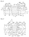
- Fig. 17 is a sectional view of a coupled state of the first plate 30 and the second plate 32 in a fifth embodiment of the invention, and shows a section in the lateral direction (direction Y1 perpendicular to the column movement direction X1) including the axis of the resin pin 61A.
- the fifth embodiment of Fig. 17 is a modified embodiment of the second embodiment of Fig. 12 showing the section in the column movement direction X1, and therefore only configurations different from those of the second embodiment will be described in the description of the fifth embodiment.
- a slide plate 43E forms a resin-pin visual check hole 65E configured by a long hole which extends in the direction Y1 perpendicular to the column movement direction X1.
- the outer diameter of a collar 62A0 is made larger than that of the head flange 63A of the resin pin 61A.
- the resin-pin visual check hole 65E includes a pair of collar visual check regions 65E1, 65E2 through which a part of the collar 62 can be visually checked, at the both ends in the longitudinal direction. Namely, a part of the first surface 63A1 of the head flange 63A of the resin pin 61A, and that of the first end surface 62A1 of the collar 62A0 are visually checked through the resin-pin visual check hole 65E including the collar visual check regions 65E1, 65E2.
- the catch of the axial elastic projections 81A disposed on the second surface 63A2 which is not opposed to the slide plate 43E, in the resin-pin visual check hole 65E can never happen. Therefore, an influence due to the above-described catch on the releasing load (increase of the releasing load) can be suppressed.
- the resin-pin visual check hole 65E may be a long hole which extends in the column movement direction X1.
- One of the pair of collar visual check regions 65E1, 65E2 of the resin-pin visual check hole 65E may be omitted.
- the shape of the resin-pin visual check hole 65E may not be a long hole but a circular hole or a polygonal hole as far as the shape enables a part of the resin pin 61A and that of the collar 62A0 to be visually checked.
- Fig. 18 is a sectional view of a coupled state of the first plate 30 and second plate 32 in a sixth embodiment of the invention, and shows a section in the lateral direction (direction Y1 perpendicular to the column movement direction X1) including the axis of the resin pin 90.
- the sixth embodiment of Fig. 18 is a modified embodiment of the third embodiment of Fig. 14 showing the section in the column movement direction X1, and therefore only configurations different from those of the third embodiment will be described in the description of the sixth embodiment.
- a slide plate 43F forms a resin-pin visual check hole 65F configured by a long hole which extends in the direction Y1 perpendicular to the column movement direction X1.
- the resin-pin visual check hole 65F includes a pair of collar visual check regions 65F1, 65F2 through which a part of the first collar 91 can be visually checked, at the both ends in the longitudinal direction. Namely, a part of the first end surface 901 of the resin pin 90, and that of the first end surface 911 of the first collar 91 are visually checked through the resin-pin visual check hole 65F including the collar visual check regions 65F1, 65F2.
- the catch of the axial elastic projections 81B in the resin-pin visual check hole 65F can never happen. Therefore, an influence due to the above-described catch on the releasing load (increase of the releasing load) can be suppressed.
- the resin-pin visual check hole 65F may be a long hole which extends in the column movement direction X1.
- One of the pair of collar visual check regions 65F1, 65F2 of the resin-pin visual check hole 65F may be omitted.
- the shape of the resin-pin visual check hole 65F may not be a long hole but a circular hole or a polygonal hole as far as the shape enables a part of the resin pin 90 and that of the first collar 91 to be visually checked.
- Fig. 19 is a sectional view of a coupled state of the first plate 30 and second plate 32 in a seventh embodiment of the invention, and shows a section in the lateral direction (direction Y1 perpendicular to a column movement direction X1) including the axis of the resin pin 90.
- the seventh embodiment of Fig. 19 is a modified embodiment of the sixth embodiment of Fig. 18 , and therefore only configurations different from those of the sixth embodiment will be described in the description of the seventh embodiment.
- the outer diameter of a second collar 92G is made larger than that of the first collar 91.
- the second collar 92G has a first end surface 921G, second end surface 922G, and center hole 923G which correspond to the first end surface 921, second end surface 922, and center hole 923 of the second collar 92 of the sixth embodiment of Fig. 18 , respectively.
- a slide plate 43G forms a resin-pin visual check hole 65G configured by a long hole which extends in the direction Y1 perpendicular to the column movement direction X1.
- the resin-pin visual check hole 65G includes a pair of collar visual check regions 65G1, 65G2 through which a part of the first collar 91 and that of the second collar 92G can be visually checked, at the both ends in the longitudinal direction. Namely, a part of the first end surface 901 of the resin pin 90, that of the first end surface 911 of the first collar 91, and that of the first end surface 921G of the second collar 92G are visually checked through the resin-pin visual check hole 65G including the collar visual check regions 65G1, 65G2.
- the catch of the axial elastic projections 81B in the resin-pin visual check hole 65G can never happen. Therefore, an influence due to the above-described catch on the releasing load (increase of the releasing load) can be suppressed.
- the resin-pin visual check hole 65G may be a long hole which extends in the column movement direction X1.
- One of the pair of collar visual check regions 65G1, 65G2 of the resin-pin visual check hole 65G may be omitted.
- the shape of the resin-pin visual check hole 65G may not be a long hole but a circular hole or a polygonal hole as far as the shape enables a part of the resin pin 90, that of the first collar 91, and that of the second collar 92 to be visually checked.
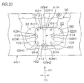
- Fig. 20 is a schematic plan view of a coupling/decoupling mechanism R1H in an eighth embodiment of the invention.
- the eighth embodiment of Fig. 20 is a modified embodiment of the first embodiment of Fig. 6 , and therefore only configurations different from those of the first embodiment will be described in the description of the eighth embodiment.
- a head flange 63H of a resin pin 61H has a rectangular shape in which the four corners are chamfered.
- the outer circumference of the head flange 63H is fitted into the first resin-pin passing hole 66 of the first plate 30 while providing a slight play in the direction of rotation about the axis of the resin pin 61H.
- Axial elastic projections 81H are projectedly formed in the four corners of a first surface 63H1 of the head flange 63H.
- the pair of flat portions 101, 102, 103, 104 (corresponding to the four side portions of a rectangle) of the outer circumference of the head flange 63H
- the pair of flat portions 101, 102 which are opposed to each other in the column movement direction X1 are engaged with a pair of flat portions 661, 662 extending in the longitudinal direction of the inner circumference of the first resin-pin passing hole 66 of the first plate 30, respectively, whereby rotation of the resin pin 61H is restricted. That is, the resin pin 61H is restricted from being rotated, directly by the first resin-pin passing hole 66 of the first plate 30 without using the collar 62H.
- the outer circumference of the collar 62H has a circular shape, and is engaged in a rotatable state with the pair of flat portions 661, 662 of the first resin-pin passing hole 66 of the first plate 30.
- the collar 62H is not restricted from being rotated, by the first resin-pin passing hole 66 of the first plate 30.
- Cutout concave portions 111 to 114 are formed in middle portions of the flat portions 101 to 104 of the outer circumference of the head flange 63H, respectively.
- the pair of cutout concave portions 111, 112 are opposed to each other in the column movement direction X1, and the other pair of cutout concave portions 113, 114 are opposed to each other in the direction Y1 perpendicular to the column movement direction X1.
- the slide plate 43H includes a resin-pin visual check hole 65H configured by a long hole which extends in the column movement direction X1.
- the resin-pin visual check hole 65H includes a pair of collar visual check regions 65H1, 65H2 which enable a first end surface 62H1 of the collar 62H to be visually checked through the pair of cutout concave portions 111, 112 of the head flange 63H of the resin pin 61H, respectively, at the both ends in the longitudinal direction.
- the catch of the axial elastic projections 81H in the resin-pin visual check hole 65H can never happen. Therefore, an influence due to the above-described catch on the releasing load (increase of the releasing load) can be suppressed.
- the resin pin 61H is restricted from being rotated, directly by the first resin-pin passing hole 66 of the first plate 30. Unlike the first embodiment of Fig. 7 , therefore, it is not necessary to dispose rotation restricting elements (the rotation restricting convex portion 82 and the rotation restricting concave portion 83) which restrict rotation of the resin pin 61, between the collar 62 and the resin pin 61, and hence the structure can be simplified.
- the resin-pin visual check hole 65H may be configured as a long hole which extends in the direction Y1 perpendicular to the column movement direction X1, and the first end surface 62H1 of the collar 62H may be visually checked through the pair of cutout concave portions 113, 114, as far as the elastic projections 81H are placed at positions which avoid a range where, in a secondary collision, the resin-pin visual check hole 65H is passed in the column movement direction X1.
- One of the pair of collar visual check regions 65H1, 65H2 of the resin-pin visual check hole 65H may be omitted.
- the shape of the resin-pin visual check hole 65H may not be a long hole but a circular hole or a polygonal hole as far as the shape enables a part of the resin pin 61H and that of the collar 62H to be visually checked.
Landscapes
- Engineering & Computer Science (AREA)
- Chemical & Material Sciences (AREA)
- Combustion & Propulsion (AREA)
- Transportation (AREA)
- Mechanical Engineering (AREA)
- Steering Controls (AREA)
- Vehicle Body Suspensions (AREA)
Abstract
Description
- The present invention relates to a steering device.
- In a steering device, in succession to a primary collision in which a vehicle collides with another vehicle, a secondary collision in which the driver collides with a steering wheel occurs. In order to absorb shock in the secondary collision, various structures in which a part of a steering column releases from the vehicle body, and is moved in the direction of the column shaft have been proposed.
- In
Fig. 9 ofPatent Reference 1, for example, a pair of engaging cutouts which extend parallel to the direction of a column shaft are disposed in a vehicle body-side bracket fixed to the vehicle body. A column-side bracket is supported through a pair of engaging capsules which are held by a plurality of engaging pins, by the engaging cutouts respectively. The engaging capsules are coupled and fixed to the column-side bracket through bolts which are passed through the engaging cutouts, respectively. - In a secondary collision, the plurality of engaging pins holding the engaging capsules are broken, whereby the engaging capsules are caused to release from the corresponding engaging cutouts, and the bolts, the engaging capsules, and the column bracket are caused to co-move with one another in the column shaft direction.
- Patent Reference 1:
JP-A-2012-121538 - When the engaging pins have play in the axial direction in housing spaces for the engaging pins, the attitudes of the engaging pins are not stabilized is a secondary collision, and there is a possibility that, for example, the engaging pins tumble (so-called falling down) in the movement direction of the column. In this case, the engaging pins cannot be smoothly sheared, and therefore there is a possibility that a stable shock absorption load cannot be obtained.
- The inventors of the present application firstly considered that a slide plate which closes the upper side of a resin pin, and which, in a secondary collision, is moved in the movement direction of the column is disposed, and an elastic repulsion force is applied to the slide plate by an axial elastic projection disposed on the resin pin. When the upper side of the resin pin is covered by the slide plate, however, it is impossible to check during production whether the resin pin is attached or not. Therefore, it was considered that a resin-pin visual check hole for visually checking a resin pin is disposed in a slide plate. However, it was noted that, in the case where the resin-pin visual check hole passes over the axial elastic projection in a secondary collision, the axial projection is caught in the resin-pin visual check hole, and it is anticipated to cause a new problem in that the releasing load is affected (increased).
- Therefore, it is an object of the invention to provide a steering device in which it is possible to, in a secondary collision, suppress an axial elastic projection of a resin pin from being caught in a resin-pin visual check hole.
- In order to attain the object, the invention provides a steering device comprising: a stationary bracket which is fixed to a vehicle body-side member, and which includes a first plate in which a first resin-pin passing hole, and a first bolt passing hole configured by a long hole that extends in a column movement direction in a secondary collision are formed; a movable jacket which is configured to rotatably support a steering shaft in which a steering member is coupled to one end; a movable bracket which is configured to support the movable jacket in a manner that, in a secondary collision, the movable bracket is moved together with the movable jacket in the column movement direction, and which includes a second plate that is opposed to a lower surface of the first plate, the second plate in which a second resin-pin passing hole and a second bolt passing hole are formed; a suspension mechanism which includes: a slide plate in which a third bolt passing hole and a resin-pin visual check hole are formed along an upper surface of the first plate; and a suspension bolt which is passed sequentially through the third bolt passing hole, the first bolt passing hole, and the second bolt passing hole to couple the first plate and the second plate together, thereby suspending the movable jacket through the movable bracket, the suspension mechanism which is movable in a corresponding column movement direction in a secondary collision; a resin pin which has an axial end surface opposed to the resin-pin visual check hole, which is passed through the first resin-pin passing hole and the second resin-pin passing hole to couple the second plate to a predetermined position of the first plate, and which, in a secondary collision, is configured to cause the second plate to release from the predetermined position in the column movement direction; and a collar which is fitted to the resin pin in a state where the collar is received directly or indirectly by a member that is suspended by the suspension mechanism, and which is higher in hardness than the resin pin, wherein, in one of the resin pin and the collar, an elastic projection which is configured to directly or indirectly urge the slide plate, and which projects in an axial direction is disposed at a position avoiding a range where, in a secondary collision, the resin-pin visual check hole is passed in the column movement direction.
- According to the configuration, in one of the resin pin and the collar, the axial elastic projection which directly or indirectly urges the slide plate is disposed at a position avoiding the range where, in a secondary collision, the resin-pin visual check hole passes in the column movement direction. Therefore, it is possible to, in a secondary collision, suppress the axial elastic projection of the resin pin from being caught in the resin-pin visual check hole. Consequently, an influence due to catching on the releasing load (increase of the releasing load) can be suppressed.
- An inner circumference of the first resin-pin passing hole, and an outer circumference of the collar may be formed into a laterally long shape which extends in a direction that is perpendicular to the column movement direction, thereby causing rotation of the collar to be restricted by the first resin-pin passing hole, the resin pin may include: a shaft portion which is passed through the collar; and a head flange which is coupled to one end of the shaft portion, the head flange may have: a first surface which is opposed to the slide plate; and a second surface which is opposed to an end surface of the collar, the elastic projection may be placed at a position avoiding the resin-pin visual check hole in the first surface of the head flange, and a rotation restricting convex portion which is disposed in at least one of the second surface of the head flange and the end surface of the collar may be fitted to a rotation restricting concave portion which is disposed on the other surface, thereby restricting relative rotation of the resin pin and the collar.
- According to the configuration, rotation of the collar is restricted by the first resin-pin passing hole, and that of the resin pin is restricted by the collar. Therefore, it is possible to surely prevent the axial elastic projection of the resin pin from being caught in the resin-pin visual check hole in a secondary collision.
- The resin pin may include: a shaft portion which is passed through the collar; and a head flange which is coupled to one end of the shaft portion, an inner circumference of the first resin-pin passing hole may include a flat portion which is engaged with a flat portion disposed on an outer circumference of the head flange, thereby restricting rotation of the resin pin, the head flange may have: a first surface which is opposed to the slide plate; and a second surface which is opposed to an end surface of the collar, and the elastic projection may be placed at a position avoiding the resin-pin visual check hole in the first surface of the head flange.
- According to the configuration, rotation of the resin pin is restricted directly by the first resin-pin passing hole. While simplifying the structure, therefore, it is possible to surely prevent the axial elastic projection of the resin pin from being caught in the resin-pin visual check hole in a secondary collision.
- The resin pin may include: a shaft portion which is passed through the collar; and a head flange which is coupled to one end of the shaft portion, the head flange may have: a first surface which is opposed to the slide plate; and a second surface which is opposed to an end surface of the collar, and the elastic projection may be disposed on the second surface of the head flange.
- According to the configuration, the head flange of the resin pin has the first surface which is opposed to the slide plate, and the second surface which is opposed to the collar, and the axial elastic projection is not disposed on the first surface, but disposed on the second surface. The catch of the axial elastic projection in the resin-pin visual check hole can never happen.
- The collar may include: a first collar which is placed in the first resin-pin passing hole, and which is press-fitted to the resin pin; and a second collar which is placed in the second resin-pin passing hole, and which is loose-fitted to the resin pin, and the elastic projection may be disposed on at least one of opposing surfaces the first collar and the second collar.
- According to the configuration, the axial elastic projection is disposed on at least one of the opposing surfaces the first collar and the second collar. Therefore, the catch of the elastic projection in the resin-pin visual check hole can never happen.
- The resin-pin visual check hole may include a collar visual check region through which a part of the collar can be visually checked.
- According to the configuration, it is possible to check not only whether the resin pin is attached or not, but also whether the collar is attached or not, through the resin-pin visual check hole.
-
- [
Fig. 1] Fig. 1 is a diagrammatic side view of a steering device of a first embodiment of the invention, and schematically shows the configuration of the steering device. - [
Fig. 2] Fig. 2 is a schematic sectional view of the steering device of the first embodiment, and shows a section taken along line II-II inFig. 1 . - [
Fig. 3] Fig. 3 is an exploded perspective view of the steering device of the first embodiment. - [
Fig. 4] Fig. 4 is a partially cutaway schematic plan view of a stationary bracket, pair of suspension mechanisms, and coupling/decoupling mechanism in the first embodiment. - [
Fig. 5] Fig. 5 is a partially cutaway schematic plan view of the stationary bracket, pair of suspension mechanisms, and coupling/decoupling mechanism, and showing a partial cutaway of a slide plate inFig. 4 . - [
Fig. 6] Fig. 6 is a partial enlarged view ofFig. 5 . - [
Fig. 7] Fig. 7 is an exploded perspective view of a resin pin and collar in the coupling/decoupling mechanism in the first embodiment. - [
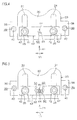
Fig. 8] Fig. 8 is a sectional view of a coupled state of first and second plates in the first embodiment, and shows a section in the lateral direction (direction perpendicular to a column movement direction) including the axis of the resin pin. - [
Fig. 9] Fig. 9 is a sectional view of the coupled state of the first and second plates in the first embodiment, and shows a section in the anteroposterior direction (column movement direction) including the axis of the resin pin. - [
Fig. 10] Fig. 10 is a sectional view of the first and second plates in the first embodiment in a secondary collision, and shows a state where the second plate is caused to release from a predetermined position of the first plate in the column movement direction by sharing of the resin pin. - [
Fig. 11] Fig. 11 is an exploded perspective view of a resin pin and collar in a coupling/decoupling mechanism in a second embodiment of the invention. - [
Fig. 12] Fig. 12 is a sectional view of a coupled state of first and second plates in the second embodiment, and shows a section in the anteroposterior direction (column movement direction) including the axis of the resin pin. - [
Fig. 13] Fig. 13 is an exploded perspective view of a resin pin and collar in a coupling/decoupling mechanism in a third embodiment of the invention. - [
Fig. 14] Fig. 14 is a sectional view of a coupled state of first and second plates in the third embodiment, and shows a section in the anteroposterior direction (column movement direction) including the axis of the resin pin. - [
Fig. 15] Fig. 15 is an exploded perspective view of a slide plate, and a resin pin and collar in a coupling/decoupling mechanism in a fourth embodiment of the invention. - [
Fig. 16] Fig. 16 is a sectional view of a coupled state of first and second plates in the fourth embodiment, and shows a section in the lateral direction (direction perpendicular to a column movement direction) including the axis of the resin pin. - [
Fig. 17] Fig. 17 is a sectional view of a coupled state of first and second plates in a fifth embodiment of the invention, and shows a section in the lateral direction (direction perpendicular to a column movement direction) including the axis of a resin pin. - [
Fig. 18] Fig. 18 is a sectional view of a coupled state of first and second plates in a sixth embodiment of the invention, and shows a section in the lateral direction (direction perpendicular to a column movement direction) including the axis of a resin pin. - [
Fig. 19] Fig. 19 is a sectional view of a coupled state of first and second plates in a seventh embodiment of the invention, and shows a section in the lateral direction (direction perpendicular to a column movement direction) including the axis of a resin pin. - [
Fig. 20] Fig. 20 is a partially cutaway schematic plan view of a slide plate, and a resin pin and collar in a coupling/decoupling mechanism in an eighth embodiment of the invention. - Preferred embodiments of the invention will be described with reference to the accompanying drawings.
-
Fig. 1 is a diagrammatic view schematically showing the configuration of a steering device of a first embodiment of the invention. Referring toFig. 1 , thesteering device 1 includes: a steering shaft 3 which is coupled to asteering member 2 such as a steering wheel; anintermediate shaft 5 which is coupled to the steering shaft 3 through auniversal joint 4; apinion shaft 7 which is coupled to theintermediate shaft 5 through a universal joint 6; and arack shaft 8 functioning as a steering shaft having arack 8a which meshes with apinion 7a disposed in the vicinity of an end portion of thepinion shaft 7. - A steering mechanism A1 is configured by a rack and pinion mechanism including the
pinion shaft 7 and therack shaft 8. Therack shaft 8 is supported by ahousing 10 fixed to a vehicle body-side member 9, so as to be movable in the axial direction (direction perpendicular to the sheet) extending along the lateral direction of a vehicle. End portions of therack shaft 8 are not illustrated, but are connected to respective steered wheels through a corresponding tie rod and a corresponding knuckle arm. - The steering shaft 3 has an
upper shaft 11 andlower shaft 12 which are connected to each other by using, for example, a spline coupling so as to be co-rotatable and axially relatively movable. The steering shaft 3 is rotatably supported by asteering column 15 fixed to vehicle body-side members - The
steering column 15 includes a tubular upper jacket 16 (movable jacket), and tubularlower jacket 17 which are fitted to each other so as to be axially relatively movable, and ahousing 18 which is connected to the axial lower end of thelower jacket 17. Areduction mechanism 20 which reduces the power of anelectric motor 19 for assisting the steering, and which transmits the reduced power to thelower shaft 12 is housed in thehousing 18. Thereduction mechanism 20 has adriving gear 21 which is co-rotatably coupled to a rotation shaft (not shown) of theelectric motor 19, and a drivengear 22 which meshes with thedriving gear 21 to co-rotate with thelower shaft 12. - Although the embodiment will be described with reference to an example in which the
steering device 1 is applied to an electric power steering device, the invention may be applied also to a manual steering device. Although the embodiment will be described with reference to an example in which thesteering device 1 is tilt-adjustable, the invention may be applied also to a steering device which is not provided with a tilt adjusting function, or that which is tilt-adjustable and telescopically adjustable. - As shown in
Fig. 2 which is a schematic sectional view, thesteering device 1 includes the pair of suspension mechanisms T1, T2 in which theupper jacket 16 is suspended by thestationary bracket 23 through thetilt bracket 24 functioning as the movable bracket. As shown inFigs. 1 and2 , namely, thetilt bracket 24 functioning as the movable bracket is suspended from thestationary bracket 23 fixed to the vehicle body-side member 13, throughsuspension bolts 25 functioning as the suspension shafts of the pair of suspension mechanisms T1, T2. By contrast, acolumn bracket 26 is fixed to theupper jacket 16 of thesteering column 15. - As shown in
Figs. 1 and2 , thesteering device 1 includes thelocking mechanism 29 which, in accordance with an operation performed on anoperation lever 27, the position of thecolumn bracket 26 which has undergone the tilt adjustment (therefore, the positions of theupper jacket 16 and the steering member 2) is locked or unlocked through thetilt bracket 24 by using afastening shaft 28. - As shown in
Figs. 2 and3 , thetilt bracket 24 includes a pair ofside plates 41. As shown inFig. 2 , thecolumn bracket 26 has a groove-like shape including a pair ofside plates 71 which are opposed to the pair ofside plates 41 of thetilt bracket 24, respectively, and acoupling plate 72 through which the lower ends of the pair ofside plates 71 are coupled to each other. - Referring to
Fig. 2 , thefastening shaft 28 is configured by a bolt which is passed through theside plates tilt bracket 24 and thecolumn bracket 26. When anut 73 screwed with thefastening shaft 28 is rotated by an operation of rotating theoperation lever 27, theside plates fastening shaft 28 and thenut 73, thereby locking theside plates member 2 after the tilt adjustment is locked, and the tilt locking is accomplished. - The
steering device 1 includes a coupling/decoupling mechanism R1 through which afirst plate 30 of thestationary bracket 23 and asecond plate 32 of thetilt bracket 24 are coupled to each other, and which, in a second collision, causes thesecond plate 32 to release from a predetermined position (position shown inFig. 9 ) of thefirst plate 30 in a column movement direction X1 as shown inFig. 10 . - As shown in
Fig. 2 andFigs. 4 and 5 which are partially cutaway schematic plan views, the coupling/decoupling mechanism R1 is placed between the pair of suspension mechanisms T1, T2 (i.e., between a pair of firstbolt passing holes 31 which will be described later, and which are in thefirst plate 30 of the stationary bracket 23) with respect to a direction Y1 that is perpendicular to the column movement direction X1. Specifically, the coupling/decoupling mechanism R1 is placed in the middle position between the pair of first bolt passing holes 31 (i.e., between the pair of suspension bolts 25) with respect to the direction Y1 that is perpendicular to the column movement direction X1. - Referring to
Fig. 1 , thestationary bracket 23 includes thefirst plate 30 which is parallel to the column movement direction X1 (corresponding to the axial direction of the steering shaft 3) in a secondary collision. In thefirst plate 30, the firstbolt passing holes 31 for the suspension mechanisms T1, T2 and configured by long holes extending parallel to the column movement direction X1 are formed. By contrast, the tilt bracket 24 (movable bracket) includes thesecond plate 32 which is opposed to thefirst plate 30. In thesecond plate 32, secondbolt passing holes 33 opposed to parts of the firstbolt passing holes 31, and for the suspension mechanisms T1, T2 are formed. - The
suspension bolts 25 are configured by bolts which are passed through the firstbolt passing holes 31 of thefirst plate 30, and the secondbolt passing holes 33 of thesecond plate 32, and which are screwed with nuts 34. Thesuspension bolts 25 which cooperate with the nuts 34 to couple thefirst plate 30 and thesecond plate 32 with each other suspend the upper jacket 16 (movable jacket) through the tilt bracket 24 (movable bracket) and thecolumn bracket 26. In a secondary collision, thesuspension bolts 25 are movable in the column movement direction X1 along the firstbolt passing holes 31 together with the tilt bracket 24 (movable bracket), thecolumn bracket 26, and theupper jacket 16. - A
lower bracket 35 which is fixed to the vehicle body-side member 14 supports atilt center shaft 36 functioning as a pivot shaft. Thetilt center shaft 36 supports thelower jacket 17 through thehousing 18 of thesteering column 15, so as to be swingable about thetilt center shaft 36. - As shown in
Figs. 2 and3 , each of the suspension mechanisms T1, T2 is configured by thesuspension bolt 25, aplate spring 42 formed by, for example, a disc spring, thenut 34, and the like. The coupling/decoupling mechanism R1 is configured by aresin pin 61 which is to be sheared in a secondary collision, and acollar 62 which is fitted to a part in the axial direction of theresin pin 61, and in which the outer circumference is formed into a laterally elongated shape such as an oblong circular shape. As the material of thecollar 62, a metal such as iron may be used, or a resin, ceramic, or the like which is higher in hardness than theresin pin 61 may be used. For example, theresin pin 61 may be formed by polyacetal resin (POM), and thecollar 62 may be formed by polyamide resin (PA) which is higher in hardness than polyacetal resin. - Referring to
Fig. 3 , thestationary bracket 23 includes a pair ofside plates 37 which are downward extended from a pair of side edges of thefirst plate 30, and a pair ofattachment plates 38 which are extended outwardly and laterally from the pair ofside plates 37, respectively. Thestationary bracket 23 is formed by, for example, sheet metal work. Theattachment plates 38 are fixed to the vehicle body-side member 13 by fixing bolts 40 (seeFig. 4 ) which are passed through screw passing holes 39 (seeFigs. 3 and4 ) disposed in theattachment plates 38, respectively. As shown inFig. 1 , therefore, thestationary bracket 23 is fixed to the vehicle body-side member 13. - In the
first plate 30 of thestationary bracket 23, referring toFigs. 2 to 4 , the firstbolt passing holes 31 are pairingly formed correspondingly with the pair ofsuspension bolts 25. The pair of firstbolt passing holes 31 extend parallel to the column movement direction X1 in a secondary collision, and are separated from each other in the direction Y1 that is perpendicular to the column movement direction X1. - As shown in
Figs. 2 and3 , the tilt bracket 24 (movable bracket) is formed by, for example, sheet metal work. Thetilt bracket 24 includes thesecond plate 32, and a pair ofside plates 41 which are downward extended from a pair of side edges of thesecond plate 32, and is formed into a groove-like shape. As shown inFigs. 2 and3 , portions where thesecond plate 32 is coupled to theside plates 41 may be formed into an arcuate shape. - In the
second plate 32 of thetilt bracket 24, the secondbolt passing holes 33 are pairingly disposed correspondingly with the pair ofsuspension bolts 25. Each of thesuspension bolts 25 is sequentially passed through theannular plate spring 42 formed by, for example, a disc spring, a corresponding thirdbolt passing hole 44 of aslide plate 43, the corresponding firstbolt passing hole 31 of thefirst plate 30, and the corresponding secondbolt passing hole 33 of thesecond plate 32, and then screwed with thenut 34. According to the configuration, thesuspension bolts 25 suspend thetilt bracket 24. - As shown in
Figs. 3 and4 , theslide plate 43 is configured by a long plate which extends in the direction Y1 that is perpendicular to the column movement direction X1, and, as shown inFig. 2 , interposed between the plate springs 42 and theupper surface 30a of thefirst plate 30. In theslide plate 43, at least the surface on the side of thefirst plate 30 is configured by a low-friction material such as a fluorine resin. Namely, the whole of theslide plate 43 may be configured by a low-friction material, or the surface of theslide plate 43 on the side of thefirst plate 30 may be covered with a low-friction material. - As shown in
Figs. 3 and9 , a first interposedplate 45 and second interposedplate 46 which, in a secondary collision, reduce the sliding resistance in the movement of thesecond plate 32 in the column movement direction X1 with respect to thefirst plate 30 are interposed between thefirst plate 30 and thesecond plate 32. - The first interposed
plate 45 constitutes a groove-like unit 45U which is engaged with afirst end portion 321 that is an end portion in the column movement direction X1 of thesecond plate 32. Namely, theunit 45U includes: the first interposedplate 45 which extends along theupper surface 32a of thesecond plate 32 and thelower surface 30b of thefirst plate 30; an opposingplate 47 which is opposed to the first interposedplate 45, and which extends along thelower surface 32b of thesecond plate 32; and acoupling plate 48 which couples the first interposedplate 45 with the opposingplate 47, and which butts against the edge in the column movement direction X1 of thesecond plate 32. - In the first interposed
plate 45, at least the surface on the side of thefirst plate 30 is configured by a low-friction material such as a fluorine resin. Namely, the first interposedplate 45 or theunit 45U may be configured by a low-friction material, or the surface of the first interposedplate 45 on the side of thefirst plate 30 may be covered with a low-friction material. - The second interposed
plate 46 constitutes aunit 46U which is engaged with asecond end portion 302 that is an end portion of thefirst plate 30 opposite to the column movement direction X1, and asecond end portion 322 that is an end portion of thesecond plate 32 opposite to the column movement direction X1. Namely, theunit 46U includes the second interposedplate 46 which extends along theupper surface 32a of thesecond plate 32 and thelower surface 30b of thefirst plate 30, and an opposingplate 49 which is opposed to the second interposedplate 46, and which extends along theupper surface 30a of thefirst plate 30. Theunit 46U further includes acoupling plate 50 which couples the second interposedplate 46 with the opposingplate 49, and which butts against the edge of thefirst plate 30 opposed to the column movement direction X1, and an engagingportion 51 which is to be hookingly engaged with thesecond end portion 322 of thesecond plate 32, and which has, for example, a hook-like shape. - In the second interposed
plate 46, at least the surface on the side of thesecond plate 32 is formed by a low-friction material such as a fluorine resin. Namely, the second interposedplate 46 or theunit 46U may be formed by a low-friction material, or the surface of the second interposedplate 46 on the side of thesecond plate 32 may be covered with a low-friction material. - As shown in
Figs. 2 and3 , each of thesuspension bolts 25 includes: ahead portion 52; a large-diameter portion 53 which is continuous to thehead portion 52, and which is smaller in diameter than thehead portion 52; a small-diameter portion 54 which is continuous to the large-diameter portion 53, and which is smaller in diameter than the large-diameter portion 53; astep portion 55 which is formed between the large-diameter portion 53 and the small-diameter portion 54; and a threadedportion 56 which is disposed in the small-diameter portion 54. Atool engagement part 57 which has, for example, a hexagonal hole shape is disposed in thehead portion 52. - As shown in
Fig. 2 , the large-diameter portion 53 is passed through theannular plate spring 42, the thirdbolt passing hole 44 of theslide plate 43, and the firstbolt passing hole 31 of thefirst plate 30. Thestep portion 55 butts against theupper surface 32a of thesecond plate 32 to be received by theupper surface 32a. Thesecond plate 32 is pressingly held between thestep portion 55 and thenut 34, and thesuspension bolts 25 and thesecond plate 32 are fixed. - The distance H1 (corresponding to the shaft length of the large-diameter portion 53) between the
head portion 52 and thestep portion 55 is made larger than the total of the thickness of the first interposed plate 45 (or that of the second interposed plate 46) which is interposed between thefirst plate 30 and thesecond plate 32, that of thefirst plate 30, that of theslide plate 43 which extends along theupper surface 30a of thefirst plate 30, and that of the plate springs 42 in the most compressed state. Therefore, the plate springs 42 elastically urges thefirst plate 30 toward thesecond plate 32 through theslide plate 43. - As shown in
Fig. 4 , theresin pin 61 of thefirst plate 30, and for the coupling/decoupling mechanism R1 is placed in the middle position between the firstbolt passing holes 31 for the suspension mechanisms T1, T2 with respect to the direction Y1 that is perpendicular to the column movement direction X1. That is, theresin pin 61 is placed in the middle position between the pair ofsuspension bolts 25 with respect to the direction Y1 that is perpendicular to the column movement direction X1. - As shown in
Fig. 5 which is is a partially cutaway view of theslide plate 43 ofFig. 4 , the first resin-pin passing hole 66 of thefirst plate 30, and for the coupling/decoupling mechanism R1 is formed into a laterally long hole which extends in the direction Y1 that is perpendicular to the column movement direction X1. Therefore, gaps S1, S2 are disposed between the outer circumference of thecollar 62 and the inner circumference of the first resin-pin passing hole 66 with respect to the direction Y1 that is perpendicular to the column movement direction X1. - Referring to
Fig. 2 ,Fig. 7 which is an exploded perspective view of the coupling/decoupling mechanism R1, andFig. 8 which is a sectional view of the coupling/decoupling mechanism R1 taken along the direction Y1 that is perpendicular to the column movement direction X1, theresin pin 61 of the coupling/decoupling mechanism R1 includes ahead flange 63 which has, for example, a circular section, and acolumnar shaft portion 64 which is smaller in diameter than thehead flange 63. - As shown in
Fig. 8 , theslide plate 43 is placed so as to cover the upper side of thehead flange 63 of theresin pin 61, thereby preventing theresin pin 61 from upwardly slipping off. In theslide plate 43, a resin-pinvisual check hole 65 which is smaller than the outer diameter of thehead flange 63 of theresin pin 61 is formed so as to be opposed to thehead portion 63. After assembling the coupling/decoupling mechanism R1, when thehead flange 63 of theresin pin 61 is viewed through the resin-pinvisual check hole 65 of theslide plate 43, it is possible to easily determine whether a working failure such as a failure of attachment of theresin pin 61 occurs or not. - The
head flange 63 of theresin pin 61 and most of thecollar 62 are inserted into the first resin-pin passing hole 66 of thefirst plate 30 of thestationary bracket 23, and for the coupling/decoupling mechanism R1. A part of thecollar 62 projects from the first resin-pin passing hole 66. In theshaft portion 64 of theresin pin 61, a part which projects from thecollar 62 is passed through a second resin-pin passing hole 67 of thesecond plate 32 of the tilt bracket 24 (movable bracket), and for the coupling/decoupling mechanism R1. - The
head flange 63 has afirst surface 631 which is opposed to theslide plate 43, and asecond surface 632 which is opposed to a first end surface 621 (upper end surface) of thecollar 62. As shown inFigs. 6 and 7 , a plurality ofelastic projections 81 that project in the axial direction of theresin pin 61 are placed at positions which, in an initial attached state, do not interfere with the resin-pinvisual check hole 65 of theslide plate 43 in a plan view, and which avoid a range where, in a secondary collision, the resin-pinvisual check hole 65 is passed in the column movement direction X1. Specifically, the plurality ofelastic projections 81 are annularly arranged so that they are arranged at regular intervals on a circumference surrounding the resin-pinvisual check hole 65 in a plan view, and the phase is at a position which avoids a range where, in a secondary collision, the resin-pinvisual check hole 65 is passed in the column movement direction X1. As shown inFig. 8 , the plurality ofelastic projections 81 are in contact with the lower surface of theslide plate 43 in a state where the projections are elastically compressed, and directly press and urge theslide plate 43 by means of an elastic repulsion force. - As shown in
Figs. 7 and8 , at least one rotation restrictingconvex portion 82 which projects toward thefirst end surface 621 of thecollar 62 is disposed on thesecond surface 632 of thehead flange 63. Moreover, a rotation restrictingconcave portion 83 which is to engage with the rotation restrictingconvex portion 82 is disposed on thefirst end surface 621 of thecollar 62. When the rotation restrictingconvex portion 82 engages with the rotation restrictingconcave portion 83, relative rotation (rotation about the center axis of the resin pin 61) of theresin pin 61 and thecollar 62 is restricted. - As shown in
Fig. 6 , by contrast, the outer circumference of thecollar 62 is formed into a laterally elongated shape such as an oblong circular shape which extends in the direction Y1 that is perpendicular to the column movement direction X1, and fitted to the first resin-pin passing hole 66 which is in thefirst plate 30, and which is a laterally long hole which extends in the direction Y1 that is perpendicular to the column movement direction X1. Therefore, rotation of thecollar 62 is restricted by the first resin-pin passing hole 66. Namely, the first resin-pin passing hole 66 restricts rotation of theresin pin 61 about the center axis of theresin pin 61 through thecollar 62. - As shown in
Figs. 6, 7 , and8 , theshaft portion 64 of theresin pin 61 is inserted into acenter hole 623 of thecollar 62. As shown inFig. 6 , the outer diameter of thecollar 62 is made larger than that of thehead flange 63 of theresin pin 61. As shown inFig. 8 , the firstaxial end surface 621 of thecollar 62 butts against thehead flange 63 of theresin pin 61, and a secondaxial end surface 622 of thecollar 62 is received by theupper surface 32a of thesecond plate 32 which is the member suspended by the suspension mechanisms T1, T2, whereby theresin pin 61 and themetal collar 62 are prevented from slipping off to the lower side of thesecond plate 32. - In a secondary collision, as shown in
Figs. 9 to 10 , theshaft portion 64 of theresin pin 61 is sheared by displacement between the matching surfaces of thesecond end surface 622 of thecollar 62 and thesecond plate 32 due to the movement of thesecond plate 32 with respect to thefirst plate 30. Namely, apart 641 of theshaft portion 64 separates from the remaining part. A shearing edge configured by the inner peripheral edge of thesecond end surface 622 of thecollar 62 has an arcuate shape, and also a shearing edge configured by the edge portion of the second resin-pin passing hole 67 of thesecond plate 32 has an arcuate shape. - According to the first embodiment, in the
resin pin 61, the axialelastic projections 81 which applies the elastic repulsion force (pressing and urging force) to theslide plate 43 are disposed at the positions which, in the initial attached state, do not interfere with the resin-pinvisual check hole 65, and which avoid a range where, in a secondary collision, the resin-pinvisual check hole 65 is passed in the column movement direction X1. Therefore, it is possible to, in a secondary collision, suppress the axialelastic projections 81 of theresin pin 61 from being caught in the resin-pinvisual check hole 65. Consequently, an influence due to catching in a secondary collision between the axialelastic projections 81 of theresin pin 61 and the resin-pinvisual check hole 65, on the releasing load (increase of the releasing load) can be suppressed. - Specifically, the inner circumference of the first resin-
pin passing hole 66, and outer circumference of thecollar 62 which are fitted to each other are formed into a laterally long shape which extends in the direction that is perpendicular to the column movement direction X1, and therefore rotation of thecollar 62 is restricted by the first resin-pin passing hole 66. Because of the engagement between the rotation restrictingconvex portion 82 and the rotation restrictingconcave portion 83, furthermore, rotation of theresin pin 61 is restricted by thecollar 62. In a secondary collision, therefore, it is possible to surely prevent theresin pin 61 from rotating about the center axis to cause theelastic projection 81 to be caught in the resin-pinvisual check hole 65. The attitude of theresin pin 61 in a secondary collision can be stabilized as far as possible. - Although not illustrated, the rotation restricting convex portion may be disposed on the
first end surface 621 of thecollar 62, and the rotation restricting concave portion may be disposed on thesecond surface 632 of thehead flange 63. - Next,
Fig. 11 is an exploded perspective view of aresin pin 61A andcollar 62A in a coupling/decoupling mechanism R1A in a second embodiment of the invention.Fig. 12 is a sectional view of a coupled state of thefirst plate 30 andsecond plate 32 in the second embodiment, and shows a section in the anteroposterior direction (column movement direction X1) including the axis of theresin pin 61A. - Referring to
Figs. 11 and 12 , theresin pin 61A includes acolumnar shaft portion 64A which is passed through a center hole 623A of anannular collar 62A, and ahead flange 63A which is coupled to one end of theshaft portion 64A. Thehead flange 63A has a first surface 63A1 which is opposed to theslide plate 43 as shown inFig. 12 , and an annular second surface 63A2 which is opposed to a first end surface 62A1 of thecollar 62A. - A plurality of axial
elastic projections 81A which are annularly arranged at regular intervals in the circumferential direction on a circumference surrounding theshaft portion 64A are formed on second surface 63A2 of thehead flange 63A. Theelastic projections 81A are contacted with the first end surface 62A1 of thecollar 62A in a state where the projections are elastically compressed, and give an elastic repulsion force to thecollar 62A. As a result, the first surface 63A1 of thehead flange 63 of theresin pin 61 is urged toward theslide plate 43, and a second end surface 62A2 of thecollar 62A is urged toward theupper surface 32a of thesecond plate 32. - The
head flange 63A and most of thecollar 62A are inserted into the first resin-pin passing hole 66 of thefirst plate 30. A part of theshaft portion 64A projects from thecollar 62A, and is inserted into the second resin-pin passing hole 67 of thesecond plate 32. - The
collar 62A is formed by a resin, ceramic, metal, or the like which is higher in hardness than theresin pin 61A. For example, theresin pin 61A may be formed by polyacetal resin (POM), and thecollar 62A may be formed by polyamide resin (PA) which is higher in hardness than polyacetal resin. - In the components of the second embodiment of
Fig. 12 , the components which are identical with the components of the first embodiment ofFig. 9 are denoted by the same reference numerals as those for the components of the first embodiment ofFig. 9 . - According to the second embodiment, the
head flange 63A of theresin pin 61A has the first surface 63A1 which is opposed to theslide plate 43, and the second surface 63A2 which is opposed to thecollar 62A, and the axialelastic projections 81A are disposed not on the first surface 63A1 but on the second surface 63A2. Theelastic projections 81A are in contact with the first surface 62A1 of thecollar 62A in which the second surface 62A2 is received by the second plate 32 (suspended member), in a state where the projections are elastically compressed. Theelastic projections 81A indirectly apply the pressing and urging force (elastic repulsion force) to theslide plate 43 through the first surface 63A1 of thehead flange 63A of theresin pin 61A. - The catch of the axial
elastic projections 81A disposed on the second surface 63A2 which is not opposed to theslide plate 43, in the resin-pinvisual check hole 65 can never happen. Therefore, an influence due to the above-described catch on the releasing load (increase of the releasing load) can be suppressed. In the second embodiment, although not illustrated, the axial elastic projections disposed on the first end surface 62A1 of thecollar 62A may butt against the second surface 63A2 of thehead flange 63A of theresin pin 61A. - Next,
Fig. 13 is an exploded perspective view of aresin pin 90 and two-step collar (first collar 91 and second collar 92) in a coupling/decoupling mechanism R1B in a third embodiment of the invention.Fig. 14 is a sectional view of a coupled state of thefirst plate 30 and thesecond plate 32 in the third embodiment, and shows a section in the anteroposterior direction (column movement direction X1) including the axis of theresin pin 90. - As shown in
Fig. 13 , theresin pin 90 has a columnar shape. Thefirst collar 91 on the side of theslide plate 43 is press-fitted to theresin pin 90, and theresin pin 90 and thefirst collar 91 are integrally movable in the axial direction. Thesecond collar 92 on the side of the second plate 32 (suspended member) is loose-fitted to theresin pin 90, and theresin pin 90 and thesecond collar 92 are relatively movable in the axial direction. - The
resin pin 90 has afirst end surface 901 andsecond end surface 902 which are opposed to each other in the axial direction. The both ends of theresin pin 90 may be formed into a conically tapered shape in order to enable theresin pin 90 to be easily inserted into center holes 913, 923 of thecollars 91, 92 (not shown). - Both the
first collar 91 and thesecond collar 92 have an annular shape. Thefirst collar 91 has afirst end surface 911 andsecond end surface 912 which are opposed to each other in the axial direction. Thesecond collar 92 has afirst end surface 921 andsecond end surface 922 which are opposed to each other in the axial direction. - The
collars resin pin 90. For example, theresin pin 90 may be formed by polyacetal resin (POM), and thecollars - As shown in
Fig. 14 , thefirst collar 91 is placed in the first resin-pin passing hole 66, and thesecond collar 92 is placed in the second resin-pin passing hole 67. Thefirst end surface 911 in the axial direction of thefirst collar 91, and thefirst end surface 901 in the axial direction of theresin pin 90 are opposed to theslide plate 43. Thefirst end surface 901 of theresin pin 90 may be flush with thefirst end surface 911 of thefirst collar 91, or project from thefirst end surface 911 of thefirst collar 91 toward theslide plate 43. Thesecond end surface 912 in the axial direction of thefirst collar 91 is opposed to thefirst end surface 921 of thesecond collar 92. Axialelastic projections 81B disposed on thesecond end surface 912 of thefirst collar 91 butt against thesecond end surface 921 of thesecond collar 92. - A
lower plate 93 is disposed along thelower surface 32b of thesecond plate 32. Thelower plate 93 is co-fastened with theslide plate 43 by suspension bolts of suspension mechanisms (corresponding to the suspension mechanisms T1, T2 ofFig. 1 ) which are not shown inFig. 14 . Thelower plate 93 functions as a slide plate which, in a secondary collision, slides in the column movement direction X1 together with thesecond plate 32 and theslide plate 43. Moreover, the lower plate 93 (corresponding to the member suspended by the suspension mechanisms T1, T2) receives the lower end surface of theresin pin 90 and thesecond end surface 922 of thesecond collar 92, and supports them so that the coupling/decoupling mechanism R1B does not drop. - In the components of the third embodiment of
Fig. 14 , the components which are identical with the components of the first embodiment ofFig. 9 are denoted by the same reference numerals as those for the components of the first embodiment ofFig. 9 . - According to the third embodiment, the
first collar 91 which is placed on the side of theslide plate 43, and which is press-fitted to theresin pin 90, and thesecond collar 92 which is placed on the side of the second plate 32 (corresponding to the suspended member), and which is loose-fitted to theresin pin 90 are stacked in two stages in the axial direction of theresin pin 90, and the axialelastic projections 81B which urge thefirst end surface 921 of thesecond collar 92 are disposed on thesecond end surface 912 of thefirst collar 91. - According to the configuration, the
second end surface 922 of thesecond collar 92 are pressed and urged against thelower plate 93. By contrast, thefirst end surface 911 of thefirst collar 91 and thefirst end surface 901 of theresin pin 90 are pressed and urged against theslide plate 43. In other words, theelastic projections 81B indirectly apply the pressing and urging force (elastic repulsion force) to theslide plate 43 through thefirst collar 91 and thefirst end surface 901 of theresin pin 90. Therefore, the attitude of theresin pin 90 which is passed through thecollars elastic projections 81B in the resin-pinvisual check hole 65 can never happen. Therefore, an influence due to the above-described catch on the releasing load (increase of the releasing load) can be suppressed. - In the third embodiment of
Fig. 14 , the axialelastic projections 81B are disposed on thesecond end surface 912 of thefirst collar 91. Alternatively, axial elastic projections (not shown) which are disposed on thefirst end surface 921 of thesecond collar 92 may butt against thesecond end surface 912 of thefirst collar 91. - In the third embodiment of
Fig. 14 , thesecond collar 92 is received by thelower plate 93 which is the member suspended by the suspension mechanisms T1, T2. Alternatively, thesecond end surface 922 of thesecond collar 92 may be received by a step portion (not shown) which is disposed in the inner circumference of the second resin-pin passing hole 67 of the second plate 32 (corresponding to the member suspended by the suspension mechanisms T1, T2). - Next,
Fig. 15 is an exploded perspective view of aslide plate 43C, and theresin pin 61 andcollar 62 in the coupling/decoupling mechanism R1 in a fourth embodiment of the invention.Fig. 16 is a sectional view of a coupled state of thefirst plate 30 and thesecond plate 32 in the fourth embodiment, and shows a section in the lateral direction (direction Y1 perpendicular to the column movement direction X1) including the axis of theresin pin 61. - The fourth embodiment of
Figs. 15 and16 is a modified embodiment of the first embodiment ofFigs. 7 and8 , and therefore only configurations different from those of the first embodiment will be described in the description of the fourth embodiment. Referring toFigs. 15 and16 , the fourth embodiment is different from the first embodiment ofFigs. 7 and8 in the following point. In the first embodiment, the single resin-pinvisual check hole 65 formed by a circular hole is disposed in theslide plate 43. In the fourth embodiment, by contrast, a pair of resin-pin visual check holes 65C, 65D which are configured by long holes that extend in the direction Y1 perpendicular to the column movement direction X1 are formed in theslide plate 43C. - The pair of resin-pin visual check holes 65C, 65D are separated from each other in the direction Y1 that is perpendicular to the column movement direction X1. The
elastic projections 81 of thefirst surface 631 of thehead flange 63 of theresin pin 61 are placed at positions which avoid a range where, in a secondary collision, the pair of resin-pin visual check holes 65C, 65D are passed in the column movement direction X1. In a secondary collision, specifically, theelastic projections 81 pass between the pair of resin-pin visual check holes 65C, 65D. - The
collar 62 is laterally longer than thehead flange 63 of theresin pin 61, and protrudes from the both sides of thehead flange 63 in the lateral direction (direction Y1 that is perpendicular to the column movement direction X1). The pair of resin-pin visual check holes 65C, 65D include collar visual check regions 65C1, 65D1 through which a part of thecollar 62 can be visually checked, respectively. Namely, a part of thefirst surface 631 of thehead flange 63 of theresin pin 61, and that of thefirst end surface 621 of thecollar 62 are visually checked through the resin-pin visual check holes 65C, 65D, respectively. - According to the fourth embodiment, similarly with the first embodiment of
Fig. 8 , an influence due to catching in a secondary collision between the axialelastic projections 81 of theresin pin 61 and the resin-pin visual check holes 65C, 65D on the releasing load (increase of the releasing load) can be suppressed. - Through the resin-pin visual check holes 65C, 65D including the collar visual check regions 65C1, 65D1, it is possible to check not only whether the
resin pin 61 is attached or not (whether a missing part exists or not), but also whether thecollar 62 is attached or not (whether a missing part exists or not). Consequently, it is possible to achieve a steering device in which the defect rate is low. - One of the pair of resin-pin visual check holes 65C, 65D may be omitted. The shapes of the resin-pin visual check holes 65C, 65D may not be a long hole but a circular hole or a polygonal hole as far as the shapes enable a part of the
resin pin 61 and that of thecollar 62 to be visually checked. - Next,
Fig. 17 is a sectional view of a coupled state of thefirst plate 30 and thesecond plate 32 in a fifth embodiment of the invention, and shows a section in the lateral direction (direction Y1 perpendicular to the column movement direction X1) including the axis of theresin pin 61A. - The fifth embodiment of
Fig. 17 is a modified embodiment of the second embodiment ofFig. 12 showing the section in the column movement direction X1, and therefore only configurations different from those of the second embodiment will be described in the description of the fifth embodiment. In the fifth embodiment, referring toFig. 17 , aslide plate 43E forms a resin-pinvisual check hole 65E configured by a long hole which extends in the direction Y1 perpendicular to the column movement direction X1. - The outer diameter of a collar 62A0 is made larger than that of the
head flange 63A of theresin pin 61A. The resin-pinvisual check hole 65E includes a pair of collar visual check regions 65E1, 65E2 through which a part of thecollar 62 can be visually checked, at the both ends in the longitudinal direction. Namely, a part of the first surface 63A1 of thehead flange 63A of theresin pin 61A, and that of the first end surface 62A1 of the collar 62A0 are visually checked through the resin-pinvisual check hole 65E including the collar visual check regions 65E1, 65E2. - In the components of the fifth embodiment of
Fig. 17 , the components which are identical with the components of the second embodiment ofFig. 12 are denoted by the same reference numerals as those for the components of the second embodiment ofFig. 12 . - According to the fifth embodiment, similarly with the second embodiment of
Fig. 12 , the catch of the axialelastic projections 81A disposed on the second surface 63A2 which is not opposed to theslide plate 43E, in the resin-pinvisual check hole 65E can never happen. Therefore, an influence due to the above-described catch on the releasing load (increase of the releasing load) can be suppressed. - Through the resin-pin
visual check hole 65E including the collar visual check regions 65E1, 65E2, it is possible to check not only whether theresin pin 61A is attached or not (whether a missing part exists or not), but also whether the collar 62A0 is attached or not (whether a missing part exists or not). Consequently, it is possible to achieve a steering device in which the defect rate is low. - The resin-pin
visual check hole 65E may be a long hole which extends in the column movement direction X1. One of the pair of collar visual check regions 65E1, 65E2 of the resin-pinvisual check hole 65E may be omitted. The shape of the resin-pinvisual check hole 65E may not be a long hole but a circular hole or a polygonal hole as far as the shape enables a part of theresin pin 61A and that of the collar 62A0 to be visually checked. - Next,
Fig. 18 is a sectional view of a coupled state of thefirst plate 30 andsecond plate 32 in a sixth embodiment of the invention, and shows a section in the lateral direction (direction Y1 perpendicular to the column movement direction X1) including the axis of theresin pin 90. - The sixth embodiment of
Fig. 18 is a modified embodiment of the third embodiment ofFig. 14 showing the section in the column movement direction X1, and therefore only configurations different from those of the third embodiment will be described in the description of the sixth embodiment. In the sixth embodiment, referring toFig. 18 , aslide plate 43F forms a resin-pinvisual check hole 65F configured by a long hole which extends in the direction Y1 perpendicular to the column movement direction X1. - The resin-pin
visual check hole 65F includes a pair of collar visual check regions 65F1, 65F2 through which a part of thefirst collar 91 can be visually checked, at the both ends in the longitudinal direction. Namely, a part of thefirst end surface 901 of theresin pin 90, and that of thefirst end surface 911 of thefirst collar 91 are visually checked through the resin-pinvisual check hole 65F including the collar visual check regions 65F1, 65F2. - In the components of the sixth embodiment of
Fig. 18 , the components which are identical with the components of the third embodiment ofFig. 14 are denoted by the same reference numerals as those for the components of the third embodiment ofFig. 14 . - According to the sixth embodiment, similarly with the third embodiment of
Fig. 14 , the catch of the axialelastic projections 81B in the resin-pinvisual check hole 65F can never happen. Therefore, an influence due to the above-described catch on the releasing load (increase of the releasing load) can be suppressed. - Through the resin-pin
visual check hole 65F including the collar visual check regions 65F1, 65F2, it is possible to check not only whether theresin pin 90 is attached or not (whether a missing part exists or not), but also whether thefirst collar 91 is attached or not (whether a missing part exists or not). Consequently, it is possible to achieve a steering device in which the defect rate is low. - The resin-pin
visual check hole 65F may be a long hole which extends in the column movement direction X1. One of the pair of collar visual check regions 65F1, 65F2 of the resin-pinvisual check hole 65F may be omitted. The shape of the resin-pinvisual check hole 65F may not be a long hole but a circular hole or a polygonal hole as far as the shape enables a part of theresin pin 90 and that of thefirst collar 91 to be visually checked. - Next,
Fig. 19 is a sectional view of a coupled state of thefirst plate 30 andsecond plate 32 in a seventh embodiment of the invention, and shows a section in the lateral direction (direction Y1 perpendicular to a column movement direction X1) including the axis of theresin pin 90. - The seventh embodiment of
Fig. 19 is a modified embodiment of the sixth embodiment ofFig. 18 , and therefore only configurations different from those of the sixth embodiment will be described in the description of the seventh embodiment. In the seventh embodiment, referring toFig. 19 , the outer diameter of asecond collar 92G is made larger than that of thefirst collar 91. Thesecond collar 92G has afirst end surface 921G,second end surface 922G, andcenter hole 923G which correspond to thefirst end surface 921,second end surface 922, andcenter hole 923 of thesecond collar 92 of the sixth embodiment ofFig. 18 , respectively. - A
slide plate 43G forms a resin-pinvisual check hole 65G configured by a long hole which extends in the direction Y1 perpendicular to the column movement direction X1. The resin-pinvisual check hole 65G includes a pair of collar visual check regions 65G1, 65G2 through which a part of thefirst collar 91 and that of thesecond collar 92G can be visually checked, at the both ends in the longitudinal direction. Namely, a part of thefirst end surface 901 of theresin pin 90, that of thefirst end surface 911 of thefirst collar 91, and that of thefirst end surface 921G of thesecond collar 92G are visually checked through the resin-pinvisual check hole 65G including the collar visual check regions 65G1, 65G2. - In the components of the seventh embodiment of
Fig. 19 , the components which are identical with the components of the sixth embodiment ofFig. 18 are denoted by the same reference numerals as those for the components of the sixth embodiment ofFig. 18 . - According to the seventh embodiment, similarly with the sixth embodiment of
Fig. 18 , the catch of the axialelastic projections 81B in the resin-pinvisual check hole 65G can never happen. Therefore, an influence due to the above-described catch on the releasing load (increase of the releasing load) can be suppressed. - Through the resin-pin
visual check hole 65G including the collar visual check regions 65G1, 65G2, it is possible to check not only whether theresin pin 90 is attached or not (whether a missing part exists or not), but also whether thefirst collar 91 and thesecond collar 92G are attached or not (whether a missing part exists or not). Consequently, it is possible to achieve a steering device in which the defect rate is low. - The resin-pin
visual check hole 65G may be a long hole which extends in the column movement direction X1. One of the pair of collar visual check regions 65G1, 65G2 of the resin-pinvisual check hole 65G may be omitted. The shape of the resin-pinvisual check hole 65G may not be a long hole but a circular hole or a polygonal hole as far as the shape enables a part of theresin pin 90, that of thefirst collar 91, and that of thesecond collar 92 to be visually checked. - Next,
Fig. 20 is a schematic plan view of a coupling/decoupling mechanism R1H in an eighth embodiment of the invention. The eighth embodiment ofFig. 20 is a modified embodiment of the first embodiment ofFig. 6 , and therefore only configurations different from those of the first embodiment will be described in the description of the eighth embodiment. - Referring to
Fig. 20 , ahead flange 63H of a resin pin 61H has a rectangular shape in which the four corners are chamfered. The outer circumference of thehead flange 63H is fitted into the first resin-pin passing hole 66 of thefirst plate 30 while providing a slight play in the direction of rotation about the axis of the resin pin 61H. Axialelastic projections 81H are projectedly formed in the four corners of a first surface 63H1 of thehead flange 63H. - Among four
flat portions head flange 63H, the pair offlat portions 101, 102 which are opposed to each other in the column movement direction X1 are engaged with a pair offlat portions pin passing hole 66 of thefirst plate 30, respectively, whereby rotation of the resin pin 61H is restricted. That is, the resin pin 61H is restricted from being rotated, directly by the first resin-pin passing hole 66 of thefirst plate 30 without using thecollar 62H. - On the other hand, the outer circumference of the
collar 62H has a circular shape, and is engaged in a rotatable state with the pair offlat portions pin passing hole 66 of thefirst plate 30. Thecollar 62H is not restricted from being rotated, by the first resin-pin passing hole 66 of thefirst plate 30. - Cutout concave portions 111 to 114 are formed in middle portions of the flat portions 101 to 104 of the outer circumference of the
head flange 63H, respectively. The pair of cutoutconcave portions 111, 112 are opposed to each other in the column movement direction X1, and the other pair of cutoutconcave portions 113, 114 are opposed to each other in the direction Y1 perpendicular to the column movement direction X1. - The
slide plate 43H includes a resin-pinvisual check hole 65H configured by a long hole which extends in the column movement direction X1. The resin-pinvisual check hole 65H includes a pair of collar visual check regions 65H1, 65H2 which enable a first end surface 62H1 of thecollar 62H to be visually checked through the pair of cutoutconcave portions 111, 112 of thehead flange 63H of the resin pin 61H, respectively, at the both ends in the longitudinal direction. - In the components of the eighth embodiment of
Fig. 20 , the components which are identical with the components of the first embodiment ofFig. 6 are denoted by the same reference numerals as those for the components of the first embodiment ofFig. 6 . - According to the eighth embodiment, similarly with the first embodiment of
Fig. 6 , the catch of the axialelastic projections 81H in the resin-pinvisual check hole 65H can never happen. Therefore, an influence due to the above-described catch on the releasing load (increase of the releasing load) can be suppressed. - Through the resin-pin
visual check hole 65H including the collar visual check regions 65H1, 65H2, it is possible to check not only whether the resin pin 61H is attached or not (whether a missing part exists or not), but also whether thecollar 62H is attached or not (whether a missing part exists or not). Consequently, it is possible to achieve a steering device in which the defect rate is low. - Moreover, the resin pin 61H is restricted from being rotated, directly by the first resin-
pin passing hole 66 of thefirst plate 30. Unlike the first embodiment ofFig. 7 , therefore, it is not necessary to dispose rotation restricting elements (the rotation restrictingconvex portion 82 and the rotation restricting concave portion 83) which restrict rotation of theresin pin 61, between thecollar 62 and theresin pin 61, and hence the structure can be simplified. - The resin-pin
visual check hole 65H may be configured as a long hole which extends in the direction Y1 perpendicular to the column movement direction X1, and the first end surface 62H1 of thecollar 62H may be visually checked through the pair of cutoutconcave portions 113, 114, as far as theelastic projections 81H are placed at positions which avoid a range where, in a secondary collision, the resin-pinvisual check hole 65H is passed in the column movement direction X1. One of the pair of collar visual check regions 65H1, 65H2 of the resin-pinvisual check hole 65H may be omitted. The shape of the resin-pinvisual check hole 65H may not be a long hole but a circular hole or a polygonal hole as far as the shape enables a part of the resin pin 61H and that of thecollar 62H to be visually checked. - The invention is not limited to the above-described embodiments, and may be modified in various manners within the scope defined by the claims of the invention.
- The application is based on Japanese Patent Application (No. 2013-149594) filed July 18, 2013 and Japanese Patent Application (No. 2013-189507) filed September 12, 2013, and their disclosures are incorporated herein by reference.
- According to the invention, it is possible to realize a steering device in which, in a secondary collision, an axial elastic projection of a resin pin can be suppressed from being caught in a resin-pin visual check hole. Description of the Reference Numerals and Signs
- 1 ... steering device, 2 ... a steering member, 3 ... steering shaft, 13 ... vehicle body-side member, 15 ... steering column, 16 ... upper jacket (movable jacket), 23 ... stationary bracket, 24 ... tilt bracket (movable bracket), 25 ... suspension bolt, 30 ... first plate, 31 ... first bolt passing hole, 32 ... second plate (member suspended by suspension mechanism), 33 ... second bolt passing hole, 34 ... nut, 42 ... plate spring, 43; 43C; 43E; 43F; 43G; 43H ... slide plate, 44 ... third bolt passing hole, 61; 61A; 61H ... resin pin, 62; 62A; 62H ... collar, 621; 62A1; 62H1 ... first end surface, 63; 63A; 63H ... head flange, 631, 63A1, 63H1 ... first surface, 632; 63A2 ... second surface, 64; 64A ... shaft portion, 65; 65C, 65D; 65E; 65F; 65G; 65H ... resin-pin visual check hole, 65C1, 65D1; 65E1, 65E2; 65F1, 65F2; 65G1, 65G2; 65H1, 65H2 ... collar visual check region, 66 ... first resin-pin passing hole, 661, 662 ... flat portion, 67 ... second resin-pin passing hole, 81; 81A; 81B ... (axial) elastic projection, 82 ... rotation restricting convex portion, 83 ... rotation restricting concave portion, 90 ... resin pin, 901 ... first end surface, 91 ... first collar, 912 ... second end surface (opposing surface), 92; 92G ... second collar, 921; 921G ... first end surface (opposing surface), 93 ... lower plate (member suspended by suspension mechanism), 101 to 104 ... flat portion, 111 to 114 ... cutout concave portion, R1; R1A; R1B; R1H ... coupling/decoupling mechanism, T1, T2 ... suspension mechanism, X1 ... column movement direction, Y1 ... direction perpendicular to column movement direction
Claims (6)
- A steering device comprising:a stationary bracket which is fixed to a vehicle body-side member, and which includes a first plate in which a first resin-pin passing hole, and a first bolt passing hole configured by a long hole that extends in a column movement direction in a secondary collision are formed;a movable jacket which is configured to rotatably support a steering shaft in which a steering member is coupled to one end;a movable bracket which is configured to support the movable jacket in a manner that, in a secondary collision, the movable bracket is moved together with the movable jacket in the column movement direction, and which includes a second plate that is opposed to a lower surface of the first plate, the second plate in which a second resin-pin passing hole and a second bolt passing holeare formed;a suspension mechanism which includes: a slide plate in which a third bolt passing hole and a resin-pin visual check hole are formed along an upper surface of the first plate; and a suspension bolt which is passed sequentially through the third bolt passing hole, the first bolt passing hole, and the second bolt passing hole to couple the first plate and the second plate together, thereby suspending the movable jacket through the movable bracket, the suspension mechanism which is movable in a corresponding column movement direction in a secondary collision;a resin pin which has an axial end surface opposed to the resin-pin visual check hole, which is passed through the first resin-pin passing hole and the second resin-pin passing hole to couple the second plate to a predetermined position of the first plate, and which, in a secondary collision, is configured to cause the second plate to release from the predetermined position in the column movement direction; anda collar which is fitted to the resin pin in a state where the collar is received directly or indirectly by a member that is suspended by the suspension mechanism, and which is higher in hardness than the resin pin, wherein,in one of the resin pin and the collar, an elastic projection which is configured to directly or indirectly urge the slide plate, and which projects in an axial direction is disposed at a position avoiding a range where, in a secondary collision, the resin-pin visual check hole is passed in the column movement direction.
- The steering device according to claim 1, wherein
an inner circumference of the first resin-pin passing hole, and an outer circumference of the collar are formed into a laterally long shape which extends in a direction that is perpendicular to the column movement direction, thereby causing rotation of the collar to be restricted by the first resin-pin passing hole,
the resin pin includes: a shaft portion which is passed through the collar; and a head flange which is coupled to one end of the shaft portion,
the head flange has: a first surface which is opposed to the slide plate; and a second surface which is opposed to an end surface of the collar,
the elastic projection is placed at a position avoiding the resin-pin visual check hole in the first surface of the head flange, and
a rotation restricting convex portion which is disposed on at least one of the second surface of the head flange and the end surface of the collar is fitted to a rotation restricting concave portion which is disposed on the other surface, thereby restricting relative rotation of the resin pin and the collar. - The steering device according to claim 1, wherein
the resin pin includes: a shaft portion which is passed through the collar; and a head flange which is coupled to one end of the shaft portion,
an inner circumference of the first resin-pin passing hole includes a flat portion which is engaged with a flat portion disposed on an outer circumference of the head flange, thereby restricting rotation of the resin pin,
the head flange has: a first surface which is opposed to the slide plate; and a second surface which is opposed to an end surface of the collar, and
the elastic projection is placed at a position avoiding the resin-pin visual check hole in the first surface of the head flange. - The steering device according to claim 1, wherein
the resin pin includes: a shaft portion which is passed through the collar; and a head flange which is coupled to one end of the shaft portion,
the head flange has: a first surface which is opposed to the slide plate; and a second surface which is opposed to an end surface of the collar, and
the elastic projection is disposed on the second surface of the head flange. - The steering device according to claim 1, wherein
the collar includes: a first collar which is placed in the first resin-pin passing hole, and which is press-fitted to the resin pin; and a second collar which is placed in the second resin-pin passing hole, and which is loose-fitted to the resin pin, and
the elastic projection is disposed on at least one of opposing surfaces the first collar and the second collar. - The steering device according to any one of claims 1 to 5, wherein
the resin-pin visual check hole includes a collar visual check region through which a part of the collar can be visually checked.
Applications Claiming Priority (3)
| Application Number | Priority Date | Filing Date | Title |
|---|---|---|---|
| JP2013149594 | 2013-07-18 | ||
| JP2013189507A JP6103536B2 (en) | 2013-07-18 | 2013-09-12 | Steering device |
| PCT/JP2014/068995 WO2015008816A1 (en) | 2013-07-18 | 2014-07-17 | Steering device |
Publications (3)
| Publication Number | Publication Date |
|---|---|
| EP3023319A1 true EP3023319A1 (en) | 2016-05-25 |
| EP3023319A4 EP3023319A4 (en) | 2016-08-10 |
| EP3023319B1 EP3023319B1 (en) | 2017-10-25 |
Family
ID=52346259
Family Applications (1)
| Application Number | Title | Priority Date | Filing Date |
|---|---|---|---|
| EP14826317.1A Not-in-force EP3023319B1 (en) | 2013-07-18 | 2014-07-17 | Steering device |
Country Status (5)
| Country | Link |
|---|---|
| US (1) | US9511792B2 (en) |
| EP (1) | EP3023319B1 (en) |
| JP (1) | JP6103536B2 (en) |
| CN (1) | CN105392687B (en) |
| WO (1) | WO2015008816A1 (en) |
Families Citing this family (1)
| Publication number | Priority date | Publication date | Assignee | Title |
|---|---|---|---|---|
| US9988070B2 (en) * | 2014-02-27 | 2018-06-05 | Kyb Corporation | Steering device |
Family Cites Families (24)
| Publication number | Priority date | Publication date | Assignee | Title |
|---|---|---|---|---|
| US5899116A (en) * | 1997-12-08 | 1999-05-04 | General Motors Corporation | Connection for energy-absorbing steering column |
| JP4126955B2 (en) * | 2002-05-08 | 2008-07-30 | 日本精工株式会社 | Shock absorbing steering column device |
| JP4062187B2 (en) * | 2003-06-27 | 2008-03-19 | 株式会社ジェイテクト | Mounting structure of shock absorbing steering device |
| KR100836909B1 (en) * | 2006-07-12 | 2008-06-11 | 현대자동차주식회사 | Shock Absorption System for Vehicle Steering Column |
| JP4897541B2 (en) * | 2007-03-30 | 2012-03-14 | 株式会社ジェイテクト | Shock absorbing steering device |
| JP5092880B2 (en) * | 2007-05-17 | 2012-12-05 | 日本精工株式会社 | Steering device |
| US8627742B2 (en) * | 2008-04-04 | 2014-01-14 | Steering Solutions Ip Holding Corporation | Steering column assembly with shearable jacket connector |
| EP2565103B1 (en) * | 2010-06-16 | 2015-04-01 | NSK Ltd. | Steering column support device |
| EP2664517B1 (en) * | 2010-10-22 | 2017-11-22 | NSK Ltd. | Steering column support device and assembly method of same |
| CN102596689B (en) * | 2010-11-02 | 2014-03-12 | 日本精工株式会社 | Support device for steering column |
| JP5327212B2 (en) * | 2010-11-16 | 2013-10-30 | 日本精工株式会社 | Steering column support device |
| WO2012063609A1 (en) | 2010-11-12 | 2012-05-18 | 日本精工株式会社 | Support device for steering column |
| EP2657104B1 (en) * | 2010-12-21 | 2017-04-26 | NSK Ltd. | Support device for steering column |
| CN102811896B (en) * | 2011-03-18 | 2015-01-21 | 日本精工株式会社 | Steering device |
| JP2013001242A (en) * | 2011-06-16 | 2013-01-07 | Jtekt Corp | Steering apparatus |
| US9016722B2 (en) * | 2011-11-18 | 2015-04-28 | Toyota Jidosha Kabushiki Kaisha | Steering column device |
| JP5789500B2 (en) * | 2011-11-29 | 2015-10-07 | 富士機工株式会社 | Steering column device |
| WO2014016886A1 (en) * | 2012-07-23 | 2014-01-30 | トヨタ自動車株式会社 | Steering column device |
| JP2014040181A (en) * | 2012-08-22 | 2014-03-06 | Jtekt Corp | Steering device |
| WO2014115685A1 (en) * | 2013-01-22 | 2014-07-31 | 日本精工株式会社 | Tilt steering apparatus |
| JP5971725B2 (en) * | 2013-01-30 | 2016-08-17 | 株式会社ジェイテクト | Steering column device |
| JP6021107B2 (en) * | 2013-01-30 | 2016-11-02 | 株式会社ジェイテクト | Steering column device |
| JP6150333B2 (en) | 2013-01-30 | 2017-06-21 | 株式会社ジェイテクト | Steering device |
| JP6115769B2 (en) * | 2013-05-24 | 2017-04-19 | 株式会社ジェイテクト | Steering device |
-
2013
- 2013-09-12 JP JP2013189507A patent/JP6103536B2/en not_active Expired - Fee Related
-
2014
- 2014-07-17 EP EP14826317.1A patent/EP3023319B1/en not_active Not-in-force
- 2014-07-17 CN CN201480040796.1A patent/CN105392687B/en not_active Expired - Fee Related
- 2014-07-17 US US14/905,509 patent/US9511792B2/en not_active Expired - Fee Related
- 2014-07-17 WO PCT/JP2014/068995 patent/WO2015008816A1/en not_active Ceased
Also Published As
| Publication number | Publication date |
|---|---|
| EP3023319B1 (en) | 2017-10-25 |
| US9511792B2 (en) | 2016-12-06 |
| CN105392687A (en) | 2016-03-09 |
| JP6103536B2 (en) | 2017-03-29 |
| US20160176435A1 (en) | 2016-06-23 |
| JP2015037923A (en) | 2015-02-26 |
| CN105392687B (en) | 2017-04-19 |
| WO2015008816A1 (en) | 2015-01-22 |
| EP3023319A4 (en) | 2016-08-10 |
Similar Documents
| Publication | Publication Date | Title |
|---|---|---|
| US9359002B2 (en) | Steering-column device | |
| US10059363B2 (en) | Steering device | |
| US9346482B2 (en) | Steering-column device | |
| US9381936B2 (en) | Steering-column device | |
| WO2012026258A1 (en) | Energy-absorbing steering device | |
| US9010806B2 (en) | Steering system | |
| EP3023319B1 (en) | Steering device | |
| JP6176654B2 (en) | Steering device | |
| EP3023320B1 (en) | Steering device | |
| EP3009326B1 (en) | Steering device |
Legal Events
| Date | Code | Title | Description |
|---|---|---|---|
| PUAI | Public reference made under article 153(3) epc to a published international application that has entered the european phase |
Free format text: ORIGINAL CODE: 0009012 |
|
| 17P | Request for examination filed |
Effective date: 20160115 |
|
| AK | Designated contracting states |
Kind code of ref document: A1 Designated state(s): AL AT BE BG CH CY CZ DE DK EE ES FI FR GB GR HR HU IE IS IT LI LT LU LV MC MK MT NL NO PL PT RO RS SE SI SK SM TR |
|
| AX | Request for extension of the european patent |
Extension state: BA ME |
|
| A4 | Supplementary search report drawn up and despatched |
Effective date: 20160711 |
|
| RIC1 | Information provided on ipc code assigned before grant |
Ipc: B62D 1/19 20060101AFI20160705BHEP |
|
| DAX | Request for extension of the european patent (deleted) | ||
| GRAP | Despatch of communication of intention to grant a patent |
Free format text: ORIGINAL CODE: EPIDOSNIGR1 |
|
| STAA | Information on the status of an ep patent application or granted ep patent |
Free format text: STATUS: GRANT OF PATENT IS INTENDED |
|
| INTG | Intention to grant announced |
Effective date: 20170418 |
|
| GRAS | Grant fee paid |
Free format text: ORIGINAL CODE: EPIDOSNIGR3 |
|
| GRAA | (expected) grant |
Free format text: ORIGINAL CODE: 0009210 |
|
| STAA | Information on the status of an ep patent application or granted ep patent |
Free format text: STATUS: THE PATENT HAS BEEN GRANTED |
|
| RIN1 | Information on inventor provided before grant (corrected) |
Inventor name: TANAKA, EIJI Inventor name: HOSHINO, SHIGERU Inventor name: IMAGAKI, SUSUMU Inventor name: NUNOMURA, SHUNSUKE |
|
| RAP1 | Party data changed (applicant data changed or rights of an application transferred) |
Owner name: TOYOTA JIDOSHA KABUSHIKI KAISHA Owner name: JTEKT CORPORATION |
|
| AK | Designated contracting states |
Kind code of ref document: B1 Designated state(s): AL AT BE BG CH CY CZ DE DK EE ES FI FR GB GR HR HU IE IS IT LI LT LU LV MC MK MT NL NO PL PT RO RS SE SI SK SM TR |
|
| REG | Reference to a national code |
Ref country code: GB Ref legal event code: FG4D |
|
| REG | Reference to a national code |
Ref country code: CH Ref legal event code: EP |
|
| REG | Reference to a national code |
Ref country code: AT Ref legal event code: REF Ref document number: 939630 Country of ref document: AT Kind code of ref document: T Effective date: 20171115 |
|
| REG | Reference to a national code |
Ref country code: IE Ref legal event code: FG4D |
|
| REG | Reference to a national code |
Ref country code: DE Ref legal event code: R096 Ref document number: 602014016407 Country of ref document: DE |
|
| REG | Reference to a national code |
Ref country code: NL Ref legal event code: MP Effective date: 20171025 |
|
| REG | Reference to a national code |
Ref country code: LT Ref legal event code: MG4D |
|
| REG | Reference to a national code |
Ref country code: AT Ref legal event code: MK05 Ref document number: 939630 Country of ref document: AT Kind code of ref document: T Effective date: 20171025 |
|
| PG25 | Lapsed in a contracting state [announced via postgrant information from national office to epo] |
Ref country code: NL Free format text: LAPSE BECAUSE OF FAILURE TO SUBMIT A TRANSLATION OF THE DESCRIPTION OR TO PAY THE FEE WITHIN THE PRESCRIBED TIME-LIMIT Effective date: 20171025 |
|
| PG25 | Lapsed in a contracting state [announced via postgrant information from national office to epo] |
Ref country code: FI Free format text: LAPSE BECAUSE OF FAILURE TO SUBMIT A TRANSLATION OF THE DESCRIPTION OR TO PAY THE FEE WITHIN THE PRESCRIBED TIME-LIMIT Effective date: 20171025 Ref country code: LT Free format text: LAPSE BECAUSE OF FAILURE TO SUBMIT A TRANSLATION OF THE DESCRIPTION OR TO PAY THE FEE WITHIN THE PRESCRIBED TIME-LIMIT Effective date: 20171025 Ref country code: SE Free format text: LAPSE BECAUSE OF FAILURE TO SUBMIT A TRANSLATION OF THE DESCRIPTION OR TO PAY THE FEE WITHIN THE PRESCRIBED TIME-LIMIT Effective date: 20171025 Ref country code: ES Free format text: LAPSE BECAUSE OF FAILURE TO SUBMIT A TRANSLATION OF THE DESCRIPTION OR TO PAY THE FEE WITHIN THE PRESCRIBED TIME-LIMIT Effective date: 20171025 Ref country code: NO Free format text: LAPSE BECAUSE OF FAILURE TO SUBMIT A TRANSLATION OF THE DESCRIPTION OR TO PAY THE FEE WITHIN THE PRESCRIBED TIME-LIMIT Effective date: 20180125 |
|
| PG25 | Lapsed in a contracting state [announced via postgrant information from national office to epo] |
Ref country code: IS Free format text: LAPSE BECAUSE OF FAILURE TO SUBMIT A TRANSLATION OF THE DESCRIPTION OR TO PAY THE FEE WITHIN THE PRESCRIBED TIME-LIMIT Effective date: 20180225 Ref country code: LV Free format text: LAPSE BECAUSE OF FAILURE TO SUBMIT A TRANSLATION OF THE DESCRIPTION OR TO PAY THE FEE WITHIN THE PRESCRIBED TIME-LIMIT Effective date: 20171025 Ref country code: BG Free format text: LAPSE BECAUSE OF FAILURE TO SUBMIT A TRANSLATION OF THE DESCRIPTION OR TO PAY THE FEE WITHIN THE PRESCRIBED TIME-LIMIT Effective date: 20180125 Ref country code: HR Free format text: LAPSE BECAUSE OF FAILURE TO SUBMIT A TRANSLATION OF THE DESCRIPTION OR TO PAY THE FEE WITHIN THE PRESCRIBED TIME-LIMIT Effective date: 20171025 Ref country code: AT Free format text: LAPSE BECAUSE OF FAILURE TO SUBMIT A TRANSLATION OF THE DESCRIPTION OR TO PAY THE FEE WITHIN THE PRESCRIBED TIME-LIMIT Effective date: 20171025 Ref country code: RS Free format text: LAPSE BECAUSE OF FAILURE TO SUBMIT A TRANSLATION OF THE DESCRIPTION OR TO PAY THE FEE WITHIN THE PRESCRIBED TIME-LIMIT Effective date: 20171025 Ref country code: GR Free format text: LAPSE BECAUSE OF FAILURE TO SUBMIT A TRANSLATION OF THE DESCRIPTION OR TO PAY THE FEE WITHIN THE PRESCRIBED TIME-LIMIT Effective date: 20180126 |
|
| REG | Reference to a national code |
Ref country code: FR Ref legal event code: PLFP Year of fee payment: 5 |
|
| REG | Reference to a national code |
Ref country code: DE Ref legal event code: R097 Ref document number: 602014016407 Country of ref document: DE |
|
| PG25 | Lapsed in a contracting state [announced via postgrant information from national office to epo] |
Ref country code: SK Free format text: LAPSE BECAUSE OF FAILURE TO SUBMIT A TRANSLATION OF THE DESCRIPTION OR TO PAY THE FEE WITHIN THE PRESCRIBED TIME-LIMIT Effective date: 20171025 Ref country code: DK Free format text: LAPSE BECAUSE OF FAILURE TO SUBMIT A TRANSLATION OF THE DESCRIPTION OR TO PAY THE FEE WITHIN THE PRESCRIBED TIME-LIMIT Effective date: 20171025 Ref country code: CY Free format text: LAPSE BECAUSE OF FAILURE TO SUBMIT A TRANSLATION OF THE DESCRIPTION OR TO PAY THE FEE WITHIN THE PRESCRIBED TIME-LIMIT Effective date: 20171025 Ref country code: EE Free format text: LAPSE BECAUSE OF FAILURE TO SUBMIT A TRANSLATION OF THE DESCRIPTION OR TO PAY THE FEE WITHIN THE PRESCRIBED TIME-LIMIT Effective date: 20171025 Ref country code: CZ Free format text: LAPSE BECAUSE OF FAILURE TO SUBMIT A TRANSLATION OF THE DESCRIPTION OR TO PAY THE FEE WITHIN THE PRESCRIBED TIME-LIMIT Effective date: 20171025 |
|
| PG25 | Lapsed in a contracting state [announced via postgrant information from national office to epo] |
Ref country code: RO Free format text: LAPSE BECAUSE OF FAILURE TO SUBMIT A TRANSLATION OF THE DESCRIPTION OR TO PAY THE FEE WITHIN THE PRESCRIBED TIME-LIMIT Effective date: 20171025 Ref country code: IT Free format text: LAPSE BECAUSE OF FAILURE TO SUBMIT A TRANSLATION OF THE DESCRIPTION OR TO PAY THE FEE WITHIN THE PRESCRIBED TIME-LIMIT Effective date: 20171025 Ref country code: SM Free format text: LAPSE BECAUSE OF FAILURE TO SUBMIT A TRANSLATION OF THE DESCRIPTION OR TO PAY THE FEE WITHIN THE PRESCRIBED TIME-LIMIT Effective date: 20171025 Ref country code: PL Free format text: LAPSE BECAUSE OF FAILURE TO SUBMIT A TRANSLATION OF THE DESCRIPTION OR TO PAY THE FEE WITHIN THE PRESCRIBED TIME-LIMIT Effective date: 20171025 |
|
| PLBE | No opposition filed within time limit |
Free format text: ORIGINAL CODE: 0009261 |
|
| STAA | Information on the status of an ep patent application or granted ep patent |
Free format text: STATUS: NO OPPOSITION FILED WITHIN TIME LIMIT |
|
| 26N | No opposition filed |
Effective date: 20180726 |
|
| PG25 | Lapsed in a contracting state [announced via postgrant information from national office to epo] |
Ref country code: SI Free format text: LAPSE BECAUSE OF FAILURE TO SUBMIT A TRANSLATION OF THE DESCRIPTION OR TO PAY THE FEE WITHIN THE PRESCRIBED TIME-LIMIT Effective date: 20171025 |
|
| REG | Reference to a national code |
Ref country code: CH Ref legal event code: PL |
|
| GBPC | Gb: european patent ceased through non-payment of renewal fee |
Effective date: 20180717 |
|
| PG25 | Lapsed in a contracting state [announced via postgrant information from national office to epo] |
Ref country code: MC Free format text: LAPSE BECAUSE OF FAILURE TO SUBMIT A TRANSLATION OF THE DESCRIPTION OR TO PAY THE FEE WITHIN THE PRESCRIBED TIME-LIMIT Effective date: 20171025 Ref country code: LU Free format text: LAPSE BECAUSE OF NON-PAYMENT OF DUE FEES Effective date: 20180717 |
|
| REG | Reference to a national code |
Ref country code: BE Ref legal event code: MM Effective date: 20180731 |
|
| REG | Reference to a national code |
Ref country code: IE Ref legal event code: MM4A |
|
| PG25 | Lapsed in a contracting state [announced via postgrant information from national office to epo] |
Ref country code: GB Free format text: LAPSE BECAUSE OF NON-PAYMENT OF DUE FEES Effective date: 20180717 Ref country code: LI Free format text: LAPSE BECAUSE OF NON-PAYMENT OF DUE FEES Effective date: 20180731 Ref country code: IE Free format text: LAPSE BECAUSE OF NON-PAYMENT OF DUE FEES Effective date: 20180717 Ref country code: CH Free format text: LAPSE BECAUSE OF NON-PAYMENT OF DUE FEES Effective date: 20180731 |
|
| PG25 | Lapsed in a contracting state [announced via postgrant information from national office to epo] |
Ref country code: BE Free format text: LAPSE BECAUSE OF NON-PAYMENT OF DUE FEES Effective date: 20180731 |
|
| PG25 | Lapsed in a contracting state [announced via postgrant information from national office to epo] |
Ref country code: MT Free format text: LAPSE BECAUSE OF NON-PAYMENT OF DUE FEES Effective date: 20180717 |
|
| PG25 | Lapsed in a contracting state [announced via postgrant information from national office to epo] |
Ref country code: TR Free format text: LAPSE BECAUSE OF FAILURE TO SUBMIT A TRANSLATION OF THE DESCRIPTION OR TO PAY THE FEE WITHIN THE PRESCRIBED TIME-LIMIT Effective date: 20171025 |
|
| PG25 | Lapsed in a contracting state [announced via postgrant information from national office to epo] |
Ref country code: PT Free format text: LAPSE BECAUSE OF FAILURE TO SUBMIT A TRANSLATION OF THE DESCRIPTION OR TO PAY THE FEE WITHIN THE PRESCRIBED TIME-LIMIT Effective date: 20171025 |
|
| PG25 | Lapsed in a contracting state [announced via postgrant information from national office to epo] |
Ref country code: MK Free format text: LAPSE BECAUSE OF NON-PAYMENT OF DUE FEES Effective date: 20171025 Ref country code: HU Free format text: LAPSE BECAUSE OF FAILURE TO SUBMIT A TRANSLATION OF THE DESCRIPTION OR TO PAY THE FEE WITHIN THE PRESCRIBED TIME-LIMIT; INVALID AB INITIO Effective date: 20140717 |
|
| PG25 | Lapsed in a contracting state [announced via postgrant information from national office to epo] |
Ref country code: AL Free format text: LAPSE BECAUSE OF FAILURE TO SUBMIT A TRANSLATION OF THE DESCRIPTION OR TO PAY THE FEE WITHIN THE PRESCRIBED TIME-LIMIT Effective date: 20171025 |
|
| PGFP | Annual fee paid to national office [announced via postgrant information from national office to epo] |
Ref country code: FR Payment date: 20210611 Year of fee payment: 8 |
|
| PGFP | Annual fee paid to national office [announced via postgrant information from national office to epo] |
Ref country code: DE Payment date: 20210622 Year of fee payment: 8 |
|
| REG | Reference to a national code |
Ref country code: DE Ref legal event code: R119 Ref document number: 602014016407 Country of ref document: DE |
|
| PG25 | Lapsed in a contracting state [announced via postgrant information from national office to epo] |
Ref country code: FR Free format text: LAPSE BECAUSE OF NON-PAYMENT OF DUE FEES Effective date: 20220731 |
|
| PG25 | Lapsed in a contracting state [announced via postgrant information from national office to epo] |
Ref country code: DE Free format text: LAPSE BECAUSE OF NON-PAYMENT OF DUE FEES Effective date: 20230201 |