EP3023301A1 - Holder for mobile device and vehicle seat employing same - Google Patents
Holder for mobile device and vehicle seat employing same Download PDFInfo
- Publication number
- EP3023301A1 EP3023301A1 EP15165804.4A EP15165804A EP3023301A1 EP 3023301 A1 EP3023301 A1 EP 3023301A1 EP 15165804 A EP15165804 A EP 15165804A EP 3023301 A1 EP3023301 A1 EP 3023301A1
- Authority
- EP
- European Patent Office
- Prior art keywords
- sliding support
- compartment
- latching
- latching assembly
- holder
- Prior art date
- Legal status (The legal status is an assumption and is not a legal conclusion. Google has not performed a legal analysis and makes no representation as to the accuracy of the status listed.)
- Withdrawn
Links
Images


Classifications
-
- B—PERFORMING OPERATIONS; TRANSPORTING
- B60—VEHICLES IN GENERAL
- B60R—VEHICLES, VEHICLE FITTINGS, OR VEHICLE PARTS, NOT OTHERWISE PROVIDED FOR
- B60R11/00—Arrangements for holding or mounting articles, not otherwise provided for
- B60R11/02—Arrangements for holding or mounting articles, not otherwise provided for for radio sets, television sets, telephones, or the like; Arrangement of controls thereof
- B60R11/0252—Arrangements for holding or mounting articles, not otherwise provided for for radio sets, television sets, telephones, or the like; Arrangement of controls thereof for personal computers, e.g. laptops, notebooks
-
- B—PERFORMING OPERATIONS; TRANSPORTING
- B60—VEHICLES IN GENERAL
- B60R—VEHICLES, VEHICLE FITTINGS, OR VEHICLE PARTS, NOT OTHERWISE PROVIDED FOR
- B60R7/00—Stowing or holding appliances inside vehicle primarily intended for personal property smaller than suit-cases, e.g. travelling articles, or maps
- B60R7/04—Stowing or holding appliances inside vehicle primarily intended for personal property smaller than suit-cases, e.g. travelling articles, or maps in driver or passenger space, e.g. using racks
-
- B—PERFORMING OPERATIONS; TRANSPORTING
- B60—VEHICLES IN GENERAL
- B60N—SEATS SPECIALLY ADAPTED FOR VEHICLES; VEHICLE PASSENGER ACCOMMODATION NOT OTHERWISE PROVIDED FOR
- B60N2/00—Seats specially adapted for vehicles; Arrangement or mounting of seats in vehicles
- B60N2/64—Back-rests or cushions
-
- B—PERFORMING OPERATIONS; TRANSPORTING
- B60—VEHICLES IN GENERAL
- B60R—VEHICLES, VEHICLE FITTINGS, OR VEHICLE PARTS, NOT OTHERWISE PROVIDED FOR
- B60R11/00—Arrangements for holding or mounting articles, not otherwise provided for
- B60R11/02—Arrangements for holding or mounting articles, not otherwise provided for for radio sets, television sets, telephones, or the like; Arrangement of controls thereof
- B60R11/0241—Arrangements for holding or mounting articles, not otherwise provided for for radio sets, television sets, telephones, or the like; Arrangement of controls thereof for telephones
-
- F—MECHANICAL ENGINEERING; LIGHTING; HEATING; WEAPONS; BLASTING
- F16—ENGINEERING ELEMENTS AND UNITS; GENERAL MEASURES FOR PRODUCING AND MAINTAINING EFFECTIVE FUNCTIONING OF MACHINES OR INSTALLATIONS; THERMAL INSULATION IN GENERAL
- F16M—FRAMES, CASINGS OR BEDS OF ENGINES, MACHINES OR APPARATUS, NOT SPECIFIC TO ENGINES, MACHINES OR APPARATUS PROVIDED FOR ELSEWHERE; STANDS; SUPPORTS
- F16M13/00—Other supports for positioning apparatus or articles; Means for steadying hand-held apparatus or articles
- F16M13/02—Other supports for positioning apparatus or articles; Means for steadying hand-held apparatus or articles for supporting on, or attaching to, an object, e.g. tree, gate, window-frame, cycle
-
- B—PERFORMING OPERATIONS; TRANSPORTING
- B60—VEHICLES IN GENERAL
- B60R—VEHICLES, VEHICLE FITTINGS, OR VEHICLE PARTS, NOT OTHERWISE PROVIDED FOR
- B60R11/00—Arrangements for holding or mounting articles, not otherwise provided for
- B60R2011/0001—Arrangements for holding or mounting articles, not otherwise provided for characterised by position
- B60R2011/0003—Arrangements for holding or mounting articles, not otherwise provided for characterised by position inside the vehicle
- B60R2011/0012—Seats or parts thereof
- B60R2011/0015—Back-rests
-
- B—PERFORMING OPERATIONS; TRANSPORTING
- B60—VEHICLES IN GENERAL
- B60R—VEHICLES, VEHICLE FITTINGS, OR VEHICLE PARTS, NOT OTHERWISE PROVIDED FOR
- B60R11/00—Arrangements for holding or mounting articles, not otherwise provided for
- B60R11/02—Arrangements for holding or mounting articles, not otherwise provided for for radio sets, television sets, telephones, or the like; Arrangement of controls thereof
- B60R2011/0276—Arrangements for holding or mounting articles, not otherwise provided for for radio sets, television sets, telephones, or the like; Arrangement of controls thereof for rear passenger use
Definitions
- the subject matter herein generally relates to holder for mobile devices, and particularly to a holder for mobile device used in a vehicle.
- Mobile computing devices such as cellular phones, tablet computers, are becoming more prevalent in today's society due to the ease in which they can be used in a mobile environment. These mobile computing devices are frequently used to view media content while traveling in vehicles.
- a holder for mobile device includes a holding structure and a mounting structure.
- the holding structure includes a holding member and a supporting member coupled to the holding member.
- the holding member is configured to hold the mobile device.
- the mounting structure includes a mounting structure, a latching assembly and a sliding support coupled to the latching assembly.
- the mounting structure defines a compartment.
- the sliding support is slidably engaged with in the compartment and transitionable between: an enclosed configuration in which the sliding support is received in the compartment to allow the latching assembly to be received in the compartment; and an exposed configuration in which the sliding support and the latching assembly are exposed to outside of the compartment to allow the latching assembly to detachably latch with the supporting member.
- a vehicle seat includes a seat back and a holder for a mobile device.
- the holder includes a holding structure, and a mounting structure.
- the holding structure includes a holding member and a supporting member coupled to the holding member.
- the holding member is configured to hold the mobile device.
- the mounting structure includes a mounting structure, a latching assembly and a sliding support coupled to the latching assembly.
- the mounting structure defines a compartment.
- the sliding support is slidably engaged with in the compartment and transitionable between: an enclosed configuration in which the sliding support is received in the compartment to allow the latching assembly to be received in the compartment; and an exposed configuration in which the sliding support and the latching assembly are exposed to outside of the compartment to allow the latching assembly to detachably latch with the supporting member.
- Coupled is defined as connected, whether directly or indirectly through intervening components, and is not necessarily limited to physical connections.
- the connection can be such that the objects are permanently connected or releasably connected.
- substantially is defined to be essentially conforming to the particular dimension, shape or other word that substantially modifies, such that the component need not be exact.
- substantially cylindrical means that the object resembles a cylinder, but can have one or more deviations from a true cylinder.
- comprising when utilized, means “including, but not necessarily limited to”; it specifically indicates open-ended inclusion or membership in the so-described combination, group, series and the like.
- FIG. 1 illustrates an isometric view of one embodiment of a vehicle seat 200 having a holder 100.
- the vehicle seat 200 includes a headrest 210 and a seat back 220 coupled to the headrest 210.
- the holder 100 is attached to a top of the seat back 220 adjacent to the headrest 210.
- FIG. 2 is similar to FIG. 1 , but showing the holder 100 in another configuration.
- the seat back 220 defines an internal cavity 223.
- the holder 100 is configured to hold a mobile device 300, such as a cellular phone or a tablet computer, such that, the mobile device 300 can be steadily held on the seat back 220 through the holder 100.
- a mobile device 300 such as a cellular phone or a tablet computer
- the holder 100 includes a holding structure 10 and a mounting structure 30 coupled to the holding structure 10.
- the holding structure 10 includes a holding member 12 and a supporting member 14 coupled to the holding member 12.
- the holding member 12 is configured to hold the mobile device 300.
- the holding member 12 has a shape similar to a protective cover, and is configured to cover on and accommodate the mobile device 300.
- the supporting member 14 can be detachably coupled to the mounting structure 30.
- the mounting structure 30 is slidably coupled to the internal cavity 223, such that the mounting structure 30 can be either completely accommodated in the internal cavity 223, or partially exposed to outside of the internal cavity 223 to hold the holding structure 10.
- FIG. 3 illustrates an exploded view of the mounting structure 30 of the holder 100.
- the mounting structure 30 includes a housing assembly 32, a sliding support 34 and a latching assembly 35.
- the housing assembly 32 includes a receiving member 321, a fixing member 322 and a shield 323.
- the receiving member 321 can be received in the internal cavity 223, and defines a compartment 3212 configured to receive the sliding support 34.
- Two opposite rails 3214 protrude from an inner wall of the compartment 3212.
- Two sliding grooves 341 are recessed in two opposite surfaces of the sliding support 34.
- the sliding grooves 341 are slidably engaged to the two rails 3214, such that the sliding support 34 slidabely engaged with the compartment 3212 to be selectively received in the compartment 3212 or exposed to outside of the compartment 3212.
- the rails 3214 can protrude from the two opposite surfaces of the sliding support 34, the sliding grooves 341 can be recessed in the compartment 3212.
- the fixing member 322 includes a main portion 3221 and an extending portion 3223 extending from the main portion 3221.
- the main portion 3221 is fixed to the seat back 220.
- the main portion 3221 includes two shoulders 3222 extending from two opposite ends thereof.
- the shoulders 3222 are fixed to the top of the seat back 220.
- the extending portion 3223 is substantially perpendicular to the main portion 3221.
- the extending portion 3223 can cover on a peripheral edge of the internal cavity 223 (see FIG. 1 ) to fix the receiving member 321 in the internal cavity 223.
- the extending portion 3223 defines an opening 3224 facing the compartment 3212 of the receiving member 321.
- the opening 3224 is configured to allow the sliding support 34 to pass through.
- the shield 323 is fixed to the sliding support 34 facing the latching assembly 35, and can move with the sliding support 34.
- the shield 323 has a shape and size corresponding the shape and size of the opening 3224, and is configured to cover the opening 3224 (see FIG. 5 ) when the sliding support 34 is received in the compartment 3212.
- FIG. 4 is similar to FIG. 3 , but showing the mounting structure 30 from another angle.
- the mounting structure 30 is also provided with a cable spool 36 rotationally engaged with the sliding support 34.
- One or more cables shown as a single cable 400, such as a USB cable, or a power cable, is coiled around the cable spool 36.
- One end of the cable 400 can be attached to a central computer (not shown) of the vehicle, another end of the cable 400 can be coupled with a connector (not shown) mating with the mobile device 300.
- the sliding support 34 slides out of the compartment 3212, the cable 400 can extracted from the cable spool 36 to allow the connector to move the sliding support 34 for a user to use.
- the sliding support 34 defines a chamber 342 adjacent to the receiving member 321 to receive the cable spool 36.
- FIG. 5 illustrates an isometric view of the mounting structure 30 as shown in FIG. 3 and FIG. 6 illustrates exploded cross section view of the mounting structure 30 as shown in FIG. 5 along lines VI-VI.
- the sliding support 34 defines a receiving groove 343 and a channel 344.
- the receiving groove 343 is configured to mounting the latching assembly 35.
- One end of the channel 344 is communicated to the receiving groove 343, another end of the channel 344 opens at a surface of the sliding support 34.
- the latching assembly 35 includes a button 351 and an elastic member 352 elastically coupled between the button 351 and a bottom wall of the receiving groove 343.
- the button 351 is slidably received in the receiving groove 343, and includes a resisting portion 3511 and a latching portion 3512 facing each other.
- the latching portion 3512 elastically resists against the elastic member 352.
- the elastic member 352 is a coil spring.
- the shield 323 has a pressing portion 3231 aligning with the resisting portion 3511. The pressing portion 3231 is configured to resist against the resisting portion 3511 to move the button 351.
- FIG. 7 is similar to FIG. 6 , but showing the supporting member 14 is latched to the button 351.
- An end of the supporting member 14 defines a latching hole 143 configured to be detachably latched to the latching portion 3512 of the button 351.
- the sliding support 34 can extends at least partially outside the compartment 3212 to expose the channel 344. In at least one embodiment, the sliding support 34 can be pulled out of the compartment 3212 manually. It can be understood that, in another embodiment, the sliding support 34 can be ejected out of the compartment 3212 by an ejecting structure (not shown).
- the supporting member 14 can inserted in and pass through the channel 344 to allow the latching hole 143 to be latched with the latching portion 3512, such that the supporting member 14 can be held by the sliding support 34 to steadily hold the mobile device 300 as shown in FIG. 2 .
- the elastic member 352 can provide a force to facilitate the latch between the latching portion 3512 and the latching hole 143.
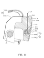
- FIG. 8 is similar to FIG. 7 , but showing the supporting member 14 is detached from the button 351.
- the pressing portion 3231 can drive the button 351 to move toward and compress the elastic member 352, such that the latching portion 3512 moves away from the latching hole 143 to detach from the latching hole 143, and the supporting member 14 can detach from the channel 344.
- the elastic member 352 can provide a force to drive the button 351 and the pressing portion 3231 to return back to their original position.
- the sliding support 34 can be retracted within the compartment 3212 to achieve a good appearance of the seat back 220, and the channel 344 can be blocked by the receiving member 321.
Landscapes
- Engineering & Computer Science (AREA)
- Mechanical Engineering (AREA)
- General Engineering & Computer Science (AREA)
- Aviation & Aerospace Engineering (AREA)
- Transportation (AREA)
- Seats For Vehicles (AREA)
- Vehicle Step Arrangements And Article Storage (AREA)
Abstract
A holder for mobile device includes a holding structure and a mounting structure. The holding structure includes a holding member and a supporting member coupled to the holding member. The holding member is configured to hold the mobile device. The mounting structure includes a mounting structure, a latching assembly and a sliding support coupled to the latching assembly. The mounting structure defines a compartment. The sliding support is slidably engaged with in the compartment and transitionable between: an enclosed configuration in which the sliding support is received in the compartment to allow the latching assembly to be received in the compartment; and an exposed configuration in which the sliding support and the latching assembly are exposed to outside of the compartment to allow the latching assembly to detachably latch with the supporting member.
Description
- This application claims priority to Taiwanese Patent Application No.
103140140 filed on November 19, 2014 - The subject matter herein generally relates to holder for mobile devices, and particularly to a holder for mobile device used in a vehicle.
- As society becomes more mobile and spends a greater amount of time traveling and away from home, demand rises for electronic devices that can be used outside the home environment. Mobile computing devices, such as cellular phones, tablet computers, are becoming more prevalent in today's society due to the ease in which they can be used in a mobile environment. These mobile computing devices are frequently used to view media content while traveling in vehicles.
- According to a first aspect of the disclosure, a holder for mobile device includes a holding structure and a mounting structure. The holding structure includes a holding member and a supporting member coupled to the holding member. The holding member is configured to hold the mobile device. The mounting structure includes a mounting structure, a latching assembly and a sliding support coupled to the latching assembly. The mounting structure defines a compartment. The sliding support is slidably engaged with in the compartment and transitionable between: an enclosed configuration in which the sliding support is received in the compartment to allow the latching assembly to be received in the compartment; and an exposed configuration in which the sliding support and the latching assembly are exposed to outside of the compartment to allow the latching assembly to detachably latch with the supporting member.
- According to a second aspect of the disclosure, a vehicle seat includes a seat back and a holder for a mobile device. The holder includes a holding structure, and a mounting structure. The holding structure includes a holding member and a supporting member coupled to the holding member. The holding member is configured to hold the mobile device. The mounting structure includes a mounting structure, a latching assembly and a sliding support coupled to the latching assembly. The mounting structure defines a compartment. The sliding support is slidably engaged with in the compartment and transitionable between: an enclosed configuration in which the sliding support is received in the compartment to allow the latching assembly to be received in the compartment; and an exposed configuration in which the sliding support and the latching assembly are exposed to outside of the compartment to allow the latching assembly to detachably latch with the supporting member.
- Implementations of the present technology will now be described, by way of example only, with reference to the attached figures.
-
FIG. 1 is an isometric view of one embodiment of a vehicle seat having a holder for mobile device. -
FIG. 2 is similar toFIG. 1 , but showing the holder in another configuration. -
FIG. 3 is an exploded view of a mounting structure of the holder as shown inFIG. 2 . -
FIG. 4 is similar toFIG. 3 , but showing the mounting structure from another angle. -
FIG. 5 is an isometric view of the mounting structure as shown inFIG. 3 . -
FIG. 6 is cross section view of the mounting structure as shown inFIG. 5 along lines VI-VI. -
FIG. 7 is similar toFIG. 6 , but showing a supporting member of the holder is latched to a button of the holder. -
FIG. 8 is similar toFIG. 7 , but showing the supporting member is detached from the button. - It will be appreciated that for simplicity and clarity of illustration, where appropriate, reference numerals have been repeated among the different figures to indicate corresponding or analogous elements. In addition, numerous specific details are set forth in order to provide a thorough understanding of the embodiments described herein. However, it will be understood by those of ordinary skill in the art that the embodiments described herein can be practiced without these specific details. In other instances, methods, procedures and components have not been described in detail so as not to obscure the related relevant feature being described. Also, the description is not to be considered as limiting the scope of the embodiments described herein. The drawings are not necessarily to scale and the proportions of certain parts may be exaggerated to better illustrate details and features of the present disclosure.
- Several definitions that apply throughout this disclosure will now be presented.
- The term "coupled" is defined as connected, whether directly or indirectly through intervening components, and is not necessarily limited to physical connections. The connection can be such that the objects are permanently connected or releasably connected. The term "substantially" is defined to be essentially conforming to the particular dimension, shape or other word that substantially modifies, such that the component need not be exact. For example, substantially cylindrical means that the object resembles a cylinder, but can have one or more deviations from a true cylinder. The term "comprising" when utilized, means "including, but not necessarily limited to"; it specifically indicates open-ended inclusion or membership in the so-described combination, group, series and the like.
-
FIG. 1 illustrates an isometric view of one embodiment of avehicle seat 200 having aholder 100. Thevehicle seat 200 includes aheadrest 210 and a seat back 220 coupled to theheadrest 210. In one embodiment, theholder 100 is attached to a top of the seat back 220 adjacent to theheadrest 210. -
FIG. 2 is similar toFIG. 1 , but showing theholder 100 in another configuration. Theseat back 220 defines aninternal cavity 223. Theholder 100 is configured to hold amobile device 300, such as a cellular phone or a tablet computer, such that, themobile device 300 can be steadily held on the seat back 220 through theholder 100. - The
holder 100 includes aholding structure 10 and amounting structure 30 coupled to theholding structure 10. Theholding structure 10 includes aholding member 12 and a supportingmember 14 coupled to theholding member 12. Theholding member 12 is configured to hold themobile device 300. In at least one embodiment, theholding member 12 has a shape similar to a protective cover, and is configured to cover on and accommodate themobile device 300. The supportingmember 14 can be detachably coupled to themounting structure 30. Themounting structure 30 is slidably coupled to theinternal cavity 223, such that themounting structure 30 can be either completely accommodated in theinternal cavity 223, or partially exposed to outside of theinternal cavity 223 to hold theholding structure 10. -
FIG. 3 illustrates an exploded view of themounting structure 30 of theholder 100. Themounting structure 30 includes ahousing assembly 32, asliding support 34 and alatching assembly 35. Thehousing assembly 32 includes a receivingmember 321, afixing member 322 and ashield 323. The receivingmember 321 can be received in theinternal cavity 223, and defines acompartment 3212 configured to receive thesliding support 34. Twoopposite rails 3214 protrude from an inner wall of thecompartment 3212. Two slidinggrooves 341 are recessed in two opposite surfaces of thesliding support 34. The slidinggrooves 341 are slidably engaged to the tworails 3214, such that thesliding support 34 slidabely engaged with thecompartment 3212 to be selectively received in thecompartment 3212 or exposed to outside of thecompartment 3212. It can be understood that, in another embodiment, therails 3214 can protrude from the two opposite surfaces of thesliding support 34, thesliding grooves 341 can be recessed in thecompartment 3212. - The fixing
member 322 includes amain portion 3221 and an extendingportion 3223 extending from themain portion 3221. Themain portion 3221 is fixed to the seat back 220. In at least one embodiment, themain portion 3221 includes twoshoulders 3222 extending from two opposite ends thereof. Theshoulders 3222 are fixed to the top of the seat back 220. The extendingportion 3223 is substantially perpendicular to themain portion 3221. The extendingportion 3223 can cover on a peripheral edge of the internal cavity 223 (seeFIG. 1 ) to fix the receivingmember 321 in theinternal cavity 223. The extendingportion 3223 defines anopening 3224 facing thecompartment 3212 of the receivingmember 321. Theopening 3224 is configured to allow the slidingsupport 34 to pass through. - The
shield 323 is fixed to the slidingsupport 34 facing the latchingassembly 35, and can move with the slidingsupport 34. Theshield 323 has a shape and size corresponding the shape and size of theopening 3224, and is configured to cover the opening 3224 (seeFIG. 5 ) when the slidingsupport 34 is received in thecompartment 3212. -
FIG. 4 is similar toFIG. 3 , but showing the mountingstructure 30 from another angle. The mountingstructure 30 is also provided with acable spool 36 rotationally engaged with the slidingsupport 34. One or more cables, shown as asingle cable 400, such as a USB cable, or a power cable, is coiled around thecable spool 36. One end of thecable 400 can be attached to a central computer (not shown) of the vehicle, another end of thecable 400 can be coupled with a connector (not shown) mating with themobile device 300. When the slidingsupport 34 slides out of thecompartment 3212, thecable 400 can extracted from thecable spool 36 to allow the connector to move the slidingsupport 34 for a user to use. In at least one embodiment, the slidingsupport 34 defines achamber 342 adjacent to the receivingmember 321 to receive thecable spool 36. -
FIG. 5 illustrates an isometric view of the mountingstructure 30 as shown inFIG. 3 andFIG. 6 illustrates exploded cross section view of the mountingstructure 30 as shown inFIG. 5 along lines VI-VI. The slidingsupport 34 defines a receivinggroove 343 and achannel 344. The receivinggroove 343 is configured to mounting the latchingassembly 35. One end of thechannel 344 is communicated to the receivinggroove 343, another end of thechannel 344 opens at a surface of the slidingsupport 34. The latchingassembly 35 includes abutton 351 and anelastic member 352 elastically coupled between thebutton 351 and a bottom wall of the receivinggroove 343. Thebutton 351 is slidably received in the receivinggroove 343, and includes a resistingportion 3511 and a latchingportion 3512 facing each other. The latchingportion 3512 elastically resists against theelastic member 352. In at least one embodiment, theelastic member 352 is a coil spring. Theshield 323 has apressing portion 3231 aligning with the resistingportion 3511. Thepressing portion 3231 is configured to resist against the resistingportion 3511 to move thebutton 351. -
FIG. 7 is similar toFIG. 6 , but showing the supportingmember 14 is latched to thebutton 351. An end of the supportingmember 14 defines alatching hole 143 configured to be detachably latched to the latchingportion 3512 of thebutton 351. The slidingsupport 34 can extends at least partially outside thecompartment 3212 to expose thechannel 344. In at least one embodiment, the slidingsupport 34 can be pulled out of thecompartment 3212 manually. It can be understood that, in another embodiment, the slidingsupport 34 can be ejected out of thecompartment 3212 by an ejecting structure (not shown). The supportingmember 14 can inserted in and pass through thechannel 344 to allow thelatching hole 143 to be latched with the latchingportion 3512, such that the supportingmember 14 can be held by the slidingsupport 34 to steadily hold themobile device 300 as shown inFIG. 2 . Theelastic member 352 can provide a force to facilitate the latch between the latchingportion 3512 and the latchinghole 143. -
FIG. 8 is similar toFIG. 7 , but showing the supportingmember 14 is detached from thebutton 351. When thepressing portion 3231 is pressed, thepressing portion 3231 can drive thebutton 351 to move toward and compress theelastic member 352, such that the latchingportion 3512 moves away from the latchinghole 143 to detach from the latchinghole 143, and the supportingmember 14 can detach from thechannel 344. In addition, when thepressing portion 3231 is released, theelastic member 352 can provide a force to drive thebutton 351 and thepressing portion 3231 to return back to their original position. The slidingsupport 34 can be retracted within thecompartment 3212 to achieve a good appearance of the seat back 220, and thechannel 344 can be blocked by the receivingmember 321. - The embodiments shown and described above are only examples. Many details are often found in the art. Therefore, many such details are neither shown nor described. Even though numerous characteristics and advantages of the present technology have been set forth in the foregoing description, together with details of the structure and function of the present disclosure, the disclosure is illustrative only, and changes may be made in the detail, including in matters of shape, size and arrangement of the parts within the principles of the present disclosure up to, and including the full extent established by the broad general meaning of the terms used in the claims. It will therefore be appreciated that the embodiments described above may be modified within the scope of the claims.
Claims (15)
- A holder for a mobile device comprising:a holding structure comprising:a holding member configured to hold the mobile device; anda supporting member coupled to the holding member;a mounting structure comprising:a receiving member defining a compartment;a latching assembly configured to detachably latch with the supporting member; anda sliding support coupled to the latching assembly and slidably engaged with in the compartment; the sliding support transitionable between: an enclosed configuration in which the sliding support is received in the compartment to allow the latching assembly to be received in the compartment; and an exposed configuration in which the sliding support and the latching assembly are exposed to outside of the compartment to allow the latching assembly to detachably latch with the supporting member.
- The holder of claim 1, wherein the sliding support defines a receiving groove and a channel communicated to the receiving groove, one end of the channel opens at a surface of the sliding support; the latching assembly is received in the receiving groove, the supporting member is configured to pass through the channel to latch with the latching assembly.
- The holder of claim 2, wherein the latching assembly comprises a button comprising a resisting portion and a latching portion facing each other, the supporting member defines a latching hole configured to detachably latch with the latching portion.
- The holder of claim 3, wherein the mounting structure further comprises a shield coupled to the sliding support and facing the resisting portion; the latching assembly further comprises an elastic member elastically coupled between the latching portion and a wall of the receiving groove; the shield has a pressing portion aligning with the resisting portion; the pressing portion is configured to resist against the resisting portion to move the button to detach the latching portion from the latching hole.
- The holder of any preceding claim, wherein one of the sliding support and the compartment defines at least one sliding groove, the other one of the sliding support and the compartment protrudes at least one rail, the at least one rail is configured to slidably engage with the at least one sliding groove.
- The holder of claim 1, 2, 3 or 4, wherein the holding member is a cover configured to cover on and accommodate the mobile device.
- The holder of claim 1, 2, 3 or 4, further comprising a cable spool rotationally engaged with the sliding support, wherein the cable spool is configured to be coiled around by a cable, and move with the sliding support when the sliding support slides.
- A vehicle seat comprising:a seat back; anda holder for a mobile device comprising:a fixing member configured to fix the receiving member to the seat back.a holding structure comprising:a holding member configured to hold the mobile device; anda supporting member coupled to the holding member;a mounting structure comprising:a receiving member defining a compartment;a latching assembly configured to detachably latch with the supporting member;at least one sliding support coupled to the latching assembly and slidably engaged with in the compartment; the at least one sliding support transitionable between: an enclosed configuration in which the at least one sliding support is received in the compartment to allow the latching assembly to be received in the compartment; and an exposed configuration in which the at least one sliding support and the latching assembly are exposed to outside of the compartment to allow the latching assembly to detachably latch with the supporting member; and
- The vehicle seat of claim 8, wherein the at least one sliding support defines a receiving groove and a channel connected to the receiving groove, one end of the channel opens at a surface of the at least one sliding support; the latching assembly is received in the receiving groove, the supporting member is configured to pass through the channel to latch with the latching assembly.
- The vehicle seat of claim 9, wherein the latching assembly comprises a button comprising a resisting portion and a latching portion facing each other, the supporting member defines a latching hole configured to detachably latch with the latching portion.
- The vehicle seat of claim 10, wherein the mounting structure further comprises a shield coupled to the at least one sliding support and facing the resisting portion; the latching assembly further comprises an elastic member elastically coupled between the latching portion and a wall of the receiving groove; the shield has a pressing portion aligning with the resisting portion; the pressing portion is configured to resist against the resisting portion to move the button to detach the latching portion from the latching hole.
- The vehicle seat of any preceding claim, wherein one of the at least one sliding support and the compartment defines at least one sliding groove, the other one of the at least one sliding support and the compartment protrudes at least one rail, the at least one rail is configured to slidably engage with the at least one sliding groove.
- The vehicle seat of claim 8, 9 10 or 11, wherein the holder further comprises a cable spool rotationally engaged with the at least one sliding support and a cable coiled around the cable spool, the cable spool is configured to move with the at least one sliding support when the at least one sliding support slides.
- The vehicle seat of claim 8, 9 10 or 11, wherein the fixing member comprises a fixing member and an extending portion extending from the fixing member; the fixing member is configured to be fixed to the seat back; the seat back defines a internal cavity configured to receiving the receiving member, the extending portion is configured to cover on a peripheral edge of the internal cavity to fix the receiving member in the internal cavity.
- The vehicle seat of claim 14, wherein the extending portion defines an opening facing the compartment of the receiving member to allow the at least one sliding support to pass through.
Applications Claiming Priority (1)
| Application Number | Priority Date | Filing Date | Title |
|---|---|---|---|
| TW103140140A TWI628095B (en) | 2014-11-19 | 2014-11-19 | Fixing device and car seat using the same |
Publications (1)
| Publication Number | Publication Date |
|---|---|
| EP3023301A1 true EP3023301A1 (en) | 2016-05-25 |
Family
ID=53039308
Family Applications (1)
| Application Number | Title | Priority Date | Filing Date |
|---|---|---|---|
| EP15165804.4A Withdrawn EP3023301A1 (en) | 2014-11-19 | 2015-04-29 | Holder for mobile device and vehicle seat employing same |
Country Status (3)
| Country | Link |
|---|---|
| US (1) | US9446719B2 (en) |
| EP (1) | EP3023301A1 (en) |
| TW (1) | TWI628095B (en) |
Cited By (1)
| Publication number | Priority date | Publication date | Assignee | Title |
|---|---|---|---|---|
| CN108791101A (en) * | 2018-05-14 | 2018-11-13 | 浙江吉利控股集团有限公司 | It is installed on IPAD holders, front-row seats of vehicle and the automobile at front-row seats of vehicle back |
Families Citing this family (13)
| Publication number | Priority date | Publication date | Assignee | Title |
|---|---|---|---|---|
| WO2017020070A1 (en) * | 2015-07-31 | 2017-02-09 | Victor Harris | Vehicle seat accessory mounting system |
| US9731600B1 (en) * | 2016-04-11 | 2017-08-15 | John White | Vehicle picture frame |
| WO2018037256A1 (en) * | 2016-08-25 | 2018-03-01 | Nsv Group Fzco | Vehicle entertainment center assembly with hanger |
| US10214154B2 (en) * | 2016-09-22 | 2019-02-26 | Lear Corporation | Vehicle seat including a support for a video device |
| DE102017216850B4 (en) | 2016-09-22 | 2024-02-15 | Lear Corporation | Vehicle seat containing a support for a video device |
| US10308192B2 (en) | 2017-08-18 | 2019-06-04 | Ford Global Technologies, Llc | Seating assembly to support a mobile computing device and method of supporting the mobile computing device with the seating assembly |
| US10207653B1 (en) * | 2018-05-21 | 2019-02-19 | Smart Product Innovations, LLC | Stowable tiered electronic device holder |
| US10875464B1 (en) * | 2019-11-14 | 2020-12-29 | Jet Optoelectronics Co., Ltd. | Vehicle seat and quick-release supporting device thereof |
| US11225202B1 (en) * | 2020-09-21 | 2022-01-18 | Ford Global Technologies, Llc | Vehicle seat display assembly |
| US20230019792A1 (en) * | 2021-07-16 | 2023-01-19 | Shenzhen Huimeng Business Information Technology Co.,Ltd | Clamping device for intelligent apparatus and multifunctional automobile neck pillow |
| CN113370861B (en) * | 2021-07-26 | 2022-09-09 | 延锋国际座椅系统有限公司 | Pop-up cover for seat functional interface |
| DE102022108898A1 (en) | 2022-04-12 | 2023-10-12 | Faurecia Autositze Gmbh | Device holder and vehicle seat |
| CN118790156A (en) * | 2023-04-13 | 2024-10-18 | 华为技术有限公司 | Support frames, carriers and seat components |
Citations (6)
| Publication number | Priority date | Publication date | Assignee | Title |
|---|---|---|---|---|
| US20010038220A1 (en) * | 2000-02-02 | 2001-11-08 | Massara Andrew J. | Stowable rear seat tray table |
| DE10212944A1 (en) * | 2001-03-22 | 2002-10-17 | Lear Corp | Video monitor console for use in vehicle pivots about upper region of holder pivotably connected to stowage compartment cover section, pivotably connected to console housing |
| EP1431107A2 (en) * | 2002-12-21 | 2004-06-23 | Adam Opel Ag | Multifunctional box for releasable attachment in the interior space of a vehicle |
| WO2007109703A2 (en) * | 2006-03-21 | 2007-09-27 | Be Aerospace , Inc. | Holster for portable ife device |
| WO2010139452A1 (en) * | 2009-06-01 | 2010-12-09 | Kinetix Ag | Fastening device |
| DE202013100414U1 (en) * | 2013-01-29 | 2013-02-04 | Airbus Operations Gmbh | Holding device for a mobile device, passenger seat with a holding device for an electronic device and vehicle |
Family Cites Families (29)
| Publication number | Priority date | Publication date | Assignee | Title |
|---|---|---|---|---|
| DE1021844B (en) | 1955-10-20 | 1958-01-02 | Organon Nv | Process for the preparation of steroid ketone oil esters |
| US4681366A (en) * | 1984-07-02 | 1987-07-21 | Irvin Industries, Inc. | Vanity mirror or vehicle accessory assembly and mounting apparatus therefor |
| USRE33423E (en) * | 1984-07-02 | 1990-11-06 | Irvin Automotive Products, Inc. | Vanity mirror or vehicle accessory assembly and mounting apparatus therefor |
| US4792183A (en) * | 1987-10-29 | 1988-12-20 | Townsend Iii William R | Desk for use in automobiles |
| US6394551B1 (en) * | 1997-12-31 | 2002-05-28 | Prince Corporation | Multi-function headrest |
| EP1260407B1 (en) * | 2001-05-25 | 2012-01-11 | Johnson Controls GmbH | Vehicle seat with integrated screen |
| US7070237B2 (en) * | 2002-08-13 | 2006-07-04 | Epsilon Electronics, Inc. | Universal vehicle headrest monitor supporting bracket assembly |
| US7149078B2 (en) * | 2003-05-15 | 2006-12-12 | Audiovox Corporation | Video display system |
| US7111814B1 (en) * | 2003-09-17 | 2006-09-26 | David Newman | Mounting arm |
| US8780282B2 (en) * | 2003-11-07 | 2014-07-15 | Voxx International Corporation | Vehicle entertainment system |
| DE102004016255B8 (en) * | 2004-04-02 | 2005-12-15 | Itw Automotive Products Gmbh & Co. Kg | Headrest for the front seats of automobiles |
| US7364230B2 (en) * | 2004-10-08 | 2008-04-29 | Edward Zheng | Portable mounting device for mobile entertainment unit |
| US7201443B2 (en) * | 2004-10-22 | 2007-04-10 | Alpine Electronics, Inc. | Method and apparatus for mounting rear seat entertainment device |
| US9987999B2 (en) * | 2006-01-04 | 2018-06-05 | Voxx International Corporation | Vehicle entertainment system and method of mounting vehicle entertainment unit |
| GB0609240D0 (en) * | 2006-05-10 | 2006-06-21 | Mitchell Ciaran | Seat top console for vehicle entertainment and accessories |
| CA2674824C (en) * | 2007-01-05 | 2014-09-30 | Audiovox Corporation | Rear seat entertainment system for a vehicle having an active headrest |
| JP5248088B2 (en) * | 2007-11-21 | 2013-07-31 | トヨタ紡織株式会社 | Monitor panel mounting structure |
| US8136777B2 (en) * | 2008-10-14 | 2012-03-20 | Audiovox Corporation | Mounting bracket for securing a video system behind a headrest |
| US20100244505A1 (en) * | 2009-03-31 | 2010-09-30 | Gm Global Technology Operations, Inc. | Video Screen Assembly For Vehicle |
| US20120125959A1 (en) * | 2009-11-03 | 2012-05-24 | Kucera Curtis C | Monitor-mounting system for a land vehicle headrest |
| US20110155873A1 (en) * | 2009-12-30 | 2011-06-30 | Winegard Company | Mounting system for releasably securing an entertainment module to an automotive headrest |
| DE102011075621A1 (en) * | 2010-05-10 | 2011-11-10 | Kinetix Ag | Device for attaching tablet computer on rear side of e.g. backrest of vehicle seat to e.g. read book, has support connected to clamping element and moved between positions, where computer screen is oriented horizontally to user in position |
| TWM398491U (en) * | 2010-10-04 | 2011-02-21 | Teng Wang | Cantilever chair hanging-rack |
| US8839501B2 (en) * | 2011-03-26 | 2014-09-23 | Bryan Ulrich McClain | Seatback-mountable holder for a portable electronic device |
| EP2694367B1 (en) * | 2011-04-04 | 2018-03-21 | BE Aerospace, Inc. | Seatback holder for tablet computers |
| US9010597B2 (en) * | 2011-07-15 | 2015-04-21 | Bby Solutions, Inc. | Headrest mount for tablet computer and method |
| US8864226B2 (en) * | 2012-07-10 | 2014-10-21 | Eagle Fan | Apparatus for hanging on seatback inside vehicle |
| US20140077539A1 (en) * | 2012-09-17 | 2014-03-20 | Atom, Enterprises, Inc. | Vehicle entertainment system |
| DE102014206125B4 (en) * | 2013-04-08 | 2022-11-24 | Kinetix Ag | Fastening means for releasably fastening a device to the backrest of a vehicle seat |
-
2014
- 2014-11-19 TW TW103140140A patent/TWI628095B/en not_active IP Right Cessation
-
2015
- 2015-03-09 US US14/641,636 patent/US9446719B2/en active Active
- 2015-04-29 EP EP15165804.4A patent/EP3023301A1/en not_active Withdrawn
Patent Citations (6)
| Publication number | Priority date | Publication date | Assignee | Title |
|---|---|---|---|---|
| US20010038220A1 (en) * | 2000-02-02 | 2001-11-08 | Massara Andrew J. | Stowable rear seat tray table |
| DE10212944A1 (en) * | 2001-03-22 | 2002-10-17 | Lear Corp | Video monitor console for use in vehicle pivots about upper region of holder pivotably connected to stowage compartment cover section, pivotably connected to console housing |
| EP1431107A2 (en) * | 2002-12-21 | 2004-06-23 | Adam Opel Ag | Multifunctional box for releasable attachment in the interior space of a vehicle |
| WO2007109703A2 (en) * | 2006-03-21 | 2007-09-27 | Be Aerospace , Inc. | Holster for portable ife device |
| WO2010139452A1 (en) * | 2009-06-01 | 2010-12-09 | Kinetix Ag | Fastening device |
| DE202013100414U1 (en) * | 2013-01-29 | 2013-02-04 | Airbus Operations Gmbh | Holding device for a mobile device, passenger seat with a holding device for an electronic device and vehicle |
Cited By (1)
| Publication number | Priority date | Publication date | Assignee | Title |
|---|---|---|---|---|
| CN108791101A (en) * | 2018-05-14 | 2018-11-13 | 浙江吉利控股集团有限公司 | It is installed on IPAD holders, front-row seats of vehicle and the automobile at front-row seats of vehicle back |
Also Published As
| Publication number | Publication date |
|---|---|
| TWI628095B (en) | 2018-07-01 |
| TW201618982A (en) | 2016-06-01 |
| US20160137140A1 (en) | 2016-05-19 |
| US9446719B2 (en) | 2016-09-20 |
Similar Documents
| Publication | Publication Date | Title |
|---|---|---|
| US9446719B2 (en) | Holder for mobile device and vehicle seat employing same | |
| US8598462B2 (en) | Cable management apparatus | |
| US8360485B2 (en) | Holding mechanism and electronic device using the same | |
| US8605425B2 (en) | Docking station for electronic device | |
| US8553407B2 (en) | Docking station for electronic device | |
| US20140185199A1 (en) | Electronic device with releasable card holder | |
| US7866991B2 (en) | Electronic device | |
| US8613629B2 (en) | Locking mechanism for connector | |
| US20130140161A1 (en) | Sliding key module and electronic device | |
| US8593803B2 (en) | Mounting apparatus for data storage device | |
| US9979117B2 (en) | Connector having waterproof function and electronic device using same | |
| US9418708B2 (en) | Data-storage device mounting apparatus | |
| US8535091B2 (en) | Fixing apparatus for connector | |
| CN103491734A (en) | Lock-holding structure and electronic device using same | |
| US8420246B2 (en) | Electronic device with sliding battery cover | |
| US7654837B2 (en) | Chip card holder and portable electronic device using same | |
| US20160136804A1 (en) | Apparatus for accommodating screws and a screw driver | |
| US9502701B1 (en) | Electronic device | |
| US20110290801A1 (en) | Cover latching mechanism | |
| US20140159558A1 (en) | Housing with lathcing mechanism | |
| US8551634B2 (en) | Computer enclosure with battery holding structure | |
| CN108598743A (en) | Card socket components and electronic equipment | |
| US20100027203A1 (en) | Latch | |
| US8293394B2 (en) | Battery cover latching mechanism | |
| US10073508B2 (en) | Power supply device and electronic device with same |
Legal Events
| Date | Code | Title | Description |
|---|---|---|---|
| AK | Designated contracting states |
Kind code of ref document: A1 Designated state(s): AL AT BE BG CH CY CZ DE DK EE ES FI FR GB GR HR HU IE IS IT LI LT LU LV MC MK MT NL NO PL PT RO RS SE SI SK SM TR |
|
| AX | Request for extension of the european patent |
Extension state: BA ME |
|
| PUAI | Public reference made under article 153(3) epc to a published international application that has entered the european phase |
Free format text: ORIGINAL CODE: 0009012 |
|
| STAA | Information on the status of an ep patent application or granted ep patent |
Free format text: STATUS: THE APPLICATION IS DEEMED TO BE WITHDRAWN |
|
| 18D | Application deemed to be withdrawn |
Effective date: 20161126 |