EP3023234A1 - Fabrication of stiffened composite panels - Google Patents
Fabrication of stiffened composite panels Download PDFInfo
- Publication number
- EP3023234A1 EP3023234A1 EP14193767.2A EP14193767A EP3023234A1 EP 3023234 A1 EP3023234 A1 EP 3023234A1 EP 14193767 A EP14193767 A EP 14193767A EP 3023234 A1 EP3023234 A1 EP 3023234A1
- Authority
- EP
- European Patent Office
- Prior art keywords
- stiffeners
- composite
- cure tool
- modules
- segments
- Prior art date
- Legal status (The legal status is an assumption and is not a legal conclusion. Google has not performed a legal analysis and makes no representation as to the accuracy of the status listed.)
- Granted
Links
- 239000002131 composite material Substances 0.000 title claims abstract description 174
- 238000004519 manufacturing process Methods 0.000 title claims description 30
- 239000003351 stiffener Substances 0.000 claims abstract description 192
- 238000000034 method Methods 0.000 claims description 49
- 238000007789 sealing Methods 0.000 claims description 10
- 238000001723 curing Methods 0.000 description 25
- 210000000569 greater omentum Anatomy 0.000 description 18
- 239000000463 material Substances 0.000 description 7
- 238000002360 preparation method Methods 0.000 description 6
- 238000010586 diagram Methods 0.000 description 4
- 230000008569 process Effects 0.000 description 4
- 239000000945 filler Substances 0.000 description 3
- 230000004048 modification Effects 0.000 description 3
- 238000012986 modification Methods 0.000 description 3
- 235000012149 noodles Nutrition 0.000 description 3
- 239000000565 sealant Substances 0.000 description 3
- 230000000712 assembly Effects 0.000 description 2
- 238000000429 assembly Methods 0.000 description 2
- 238000005520 cutting process Methods 0.000 description 2
- 239000000835 fiber Substances 0.000 description 2
- 238000012423 maintenance Methods 0.000 description 2
- 230000002093 peripheral effect Effects 0.000 description 2
- 230000000284 resting effect Effects 0.000 description 2
- 239000003381 stabilizer Substances 0.000 description 2
- 239000004593 Epoxy Substances 0.000 description 1
- 239000000853 adhesive Substances 0.000 description 1
- 230000001070 adhesive effect Effects 0.000 description 1
- 239000004918 carbon fiber reinforced polymer Substances 0.000 description 1
- 238000010276 construction Methods 0.000 description 1
- 230000001934 delay Effects 0.000 description 1
- 238000013461 design Methods 0.000 description 1
- 230000007613 environmental effect Effects 0.000 description 1
- 239000012530 fluid Substances 0.000 description 1
- 238000009787 hand lay-up Methods 0.000 description 1
- 230000010354 integration Effects 0.000 description 1
- 238000003475 lamination Methods 0.000 description 1
- 230000007246 mechanism Effects 0.000 description 1
- 230000008520 organization Effects 0.000 description 1
- 238000009419 refurbishment Methods 0.000 description 1
- 230000000087 stabilizing effect Effects 0.000 description 1
- 238000012546 transfer Methods 0.000 description 1
- 238000003466 welding Methods 0.000 description 1
Images


Classifications
-
- B—PERFORMING OPERATIONS; TRANSPORTING
- B29—WORKING OF PLASTICS; WORKING OF SUBSTANCES IN A PLASTIC STATE IN GENERAL
- B29C—SHAPING OR JOINING OF PLASTICS; SHAPING OF MATERIAL IN A PLASTIC STATE, NOT OTHERWISE PROVIDED FOR; AFTER-TREATMENT OF THE SHAPED PRODUCTS, e.g. REPAIRING
- B29C70/00—Shaping composites, i.e. plastics material comprising reinforcements, fillers or preformed parts, e.g. inserts
- B29C70/04—Shaping composites, i.e. plastics material comprising reinforcements, fillers or preformed parts, e.g. inserts comprising reinforcements only, e.g. self-reinforcing plastics
- B29C70/28—Shaping operations therefor
- B29C70/40—Shaping or impregnating by compression not applied
- B29C70/42—Shaping or impregnating by compression not applied for producing articles of definite length, i.e. discrete articles
- B29C70/44—Shaping or impregnating by compression not applied for producing articles of definite length, i.e. discrete articles using isostatic pressure, e.g. pressure difference-moulding, vacuum bag-moulding, autoclave-moulding or expanding rubber-moulding
-
- B—PERFORMING OPERATIONS; TRANSPORTING
- B29—WORKING OF PLASTICS; WORKING OF SUBSTANCES IN A PLASTIC STATE IN GENERAL
- B29C—SHAPING OR JOINING OF PLASTICS; SHAPING OF MATERIAL IN A PLASTIC STATE, NOT OTHERWISE PROVIDED FOR; AFTER-TREATMENT OF THE SHAPED PRODUCTS, e.g. REPAIRING
- B29C33/00—Moulds or cores; Details thereof or accessories therefor
- B29C33/30—Mounting, exchanging or centering
- B29C33/301—Modular mould systems [MMS], i.e. moulds built up by stacking mould elements, e.g. plates, blocks, rods
-
- B—PERFORMING OPERATIONS; TRANSPORTING
- B29—WORKING OF PLASTICS; WORKING OF SUBSTANCES IN A PLASTIC STATE IN GENERAL
- B29C—SHAPING OR JOINING OF PLASTICS; SHAPING OF MATERIAL IN A PLASTIC STATE, NOT OTHERWISE PROVIDED FOR; AFTER-TREATMENT OF THE SHAPED PRODUCTS, e.g. REPAIRING
- B29C65/00—Joining or sealing of preformed parts, e.g. welding of plastics materials; Apparatus therefor
- B29C65/02—Joining or sealing of preformed parts, e.g. welding of plastics materials; Apparatus therefor by heating, with or without pressure
-
- B—PERFORMING OPERATIONS; TRANSPORTING
- B29—WORKING OF PLASTICS; WORKING OF SUBSTANCES IN A PLASTIC STATE IN GENERAL
- B29C—SHAPING OR JOINING OF PLASTICS; SHAPING OF MATERIAL IN A PLASTIC STATE, NOT OTHERWISE PROVIDED FOR; AFTER-TREATMENT OF THE SHAPED PRODUCTS, e.g. REPAIRING
- B29C65/00—Joining or sealing of preformed parts, e.g. welding of plastics materials; Apparatus therefor
- B29C65/78—Means for handling the parts to be joined, e.g. for making containers or hollow articles, e.g. means for handling sheets, plates, web-like materials, tubular articles, hollow articles or elements to be joined therewith; Means for discharging the joined articles from the joining apparatus
- B29C65/7802—Positioning the parts to be joined, e.g. aligning, indexing or centring
-
- B—PERFORMING OPERATIONS; TRANSPORTING
- B29—WORKING OF PLASTICS; WORKING OF SUBSTANCES IN A PLASTIC STATE IN GENERAL
- B29C—SHAPING OR JOINING OF PLASTICS; SHAPING OF MATERIAL IN A PLASTIC STATE, NOT OTHERWISE PROVIDED FOR; AFTER-TREATMENT OF THE SHAPED PRODUCTS, e.g. REPAIRING
- B29C65/00—Joining or sealing of preformed parts, e.g. welding of plastics materials; Apparatus therefor
- B29C65/78—Means for handling the parts to be joined, e.g. for making containers or hollow articles, e.g. means for handling sheets, plates, web-like materials, tubular articles, hollow articles or elements to be joined therewith; Means for discharging the joined articles from the joining apparatus
- B29C65/7841—Holding or clamping means for handling purposes
- B29C65/7847—Holding or clamping means for handling purposes using vacuum to hold at least one of the parts to be joined
-
- B—PERFORMING OPERATIONS; TRANSPORTING
- B29—WORKING OF PLASTICS; WORKING OF SUBSTANCES IN A PLASTIC STATE IN GENERAL
- B29C—SHAPING OR JOINING OF PLASTICS; SHAPING OF MATERIAL IN A PLASTIC STATE, NOT OTHERWISE PROVIDED FOR; AFTER-TREATMENT OF THE SHAPED PRODUCTS, e.g. REPAIRING
- B29C66/00—General aspects of processes or apparatus for joining preformed parts
- B29C66/01—General aspects dealing with the joint area or with the area to be joined
- B29C66/05—Particular design of joint configurations
- B29C66/10—Particular design of joint configurations particular design of the joint cross-sections
- B29C66/11—Joint cross-sections comprising a single joint-segment, i.e. one of the parts to be joined comprising a single joint-segment in the joint cross-section
- B29C66/112—Single lapped joints
- B29C66/1122—Single lap to lap joints, i.e. overlap joints
-
- B—PERFORMING OPERATIONS; TRANSPORTING
- B29—WORKING OF PLASTICS; WORKING OF SUBSTANCES IN A PLASTIC STATE IN GENERAL
- B29C—SHAPING OR JOINING OF PLASTICS; SHAPING OF MATERIAL IN A PLASTIC STATE, NOT OTHERWISE PROVIDED FOR; AFTER-TREATMENT OF THE SHAPED PRODUCTS, e.g. REPAIRING
- B29C66/00—General aspects of processes or apparatus for joining preformed parts
- B29C66/50—General aspects of joining tubular articles; General aspects of joining long products, i.e. bars or profiled elements; General aspects of joining single elements to tubular articles, hollow articles or bars; General aspects of joining several hollow-preforms to form hollow or tubular articles
- B29C66/51—Joining tubular articles, profiled elements or bars; Joining single elements to tubular articles, hollow articles or bars; Joining several hollow-preforms to form hollow or tubular articles
- B29C66/54—Joining several hollow-preforms, e.g. half-shells, to form hollow articles, e.g. for making balls, containers; Joining several hollow-preforms, e.g. half-cylinders, to form tubular articles
- B29C66/543—Joining several hollow-preforms, e.g. half-shells, to form hollow articles, e.g. for making balls, containers; Joining several hollow-preforms, e.g. half-cylinders, to form tubular articles joining more than two hollow-preforms to form said hollow articles
-
- B—PERFORMING OPERATIONS; TRANSPORTING
- B29—WORKING OF PLASTICS; WORKING OF SUBSTANCES IN A PLASTIC STATE IN GENERAL
- B29C—SHAPING OR JOINING OF PLASTICS; SHAPING OF MATERIAL IN A PLASTIC STATE, NOT OTHERWISE PROVIDED FOR; AFTER-TREATMENT OF THE SHAPED PRODUCTS, e.g. REPAIRING
- B29C66/00—General aspects of processes or apparatus for joining preformed parts
- B29C66/50—General aspects of joining tubular articles; General aspects of joining long products, i.e. bars or profiled elements; General aspects of joining single elements to tubular articles, hollow articles or bars; General aspects of joining several hollow-preforms to form hollow or tubular articles
- B29C66/63—Internally supporting the article during joining
-
- B—PERFORMING OPERATIONS; TRANSPORTING
- B29—WORKING OF PLASTICS; WORKING OF SUBSTANCES IN A PLASTIC STATE IN GENERAL
- B29C—SHAPING OR JOINING OF PLASTICS; SHAPING OF MATERIAL IN A PLASTIC STATE, NOT OTHERWISE PROVIDED FOR; AFTER-TREATMENT OF THE SHAPED PRODUCTS, e.g. REPAIRING
- B29C66/00—General aspects of processes or apparatus for joining preformed parts
- B29C66/70—General aspects of processes or apparatus for joining preformed parts characterised by the composition, physical properties or the structure of the material of the parts to be joined; Joining with non-plastics material
- B29C66/72—General aspects of processes or apparatus for joining preformed parts characterised by the composition, physical properties or the structure of the material of the parts to be joined; Joining with non-plastics material characterised by the structure of the material of the parts to be joined
- B29C66/721—Fibre-reinforced materials
-
- B—PERFORMING OPERATIONS; TRANSPORTING
- B29—WORKING OF PLASTICS; WORKING OF SUBSTANCES IN A PLASTIC STATE IN GENERAL
- B29C—SHAPING OR JOINING OF PLASTICS; SHAPING OF MATERIAL IN A PLASTIC STATE, NOT OTHERWISE PROVIDED FOR; AFTER-TREATMENT OF THE SHAPED PRODUCTS, e.g. REPAIRING
- B29C66/00—General aspects of processes or apparatus for joining preformed parts
- B29C66/80—General aspects of machine operations or constructions and parts thereof
- B29C66/81—General aspects of the pressing elements, i.e. the elements applying pressure on the parts to be joined in the area to be joined, e.g. the welding jaws or clamps
- B29C66/814—General aspects of the pressing elements, i.e. the elements applying pressure on the parts to be joined in the area to be joined, e.g. the welding jaws or clamps characterised by the design of the pressing elements, e.g. of the welding jaws or clamps
- B29C66/8141—General aspects of the pressing elements, i.e. the elements applying pressure on the parts to be joined in the area to be joined, e.g. the welding jaws or clamps characterised by the design of the pressing elements, e.g. of the welding jaws or clamps characterised by the surface geometry of the part of the pressing elements, e.g. welding jaws or clamps, coming into contact with the parts to be joined
- B29C66/81411—General aspects of the pressing elements, i.e. the elements applying pressure on the parts to be joined in the area to be joined, e.g. the welding jaws or clamps characterised by the design of the pressing elements, e.g. of the welding jaws or clamps characterised by the surface geometry of the part of the pressing elements, e.g. welding jaws or clamps, coming into contact with the parts to be joined characterised by its cross-section, e.g. transversal or longitudinal, being non-flat
- B29C66/81421—General aspects of the pressing elements, i.e. the elements applying pressure on the parts to be joined in the area to be joined, e.g. the welding jaws or clamps characterised by the design of the pressing elements, e.g. of the welding jaws or clamps characterised by the surface geometry of the part of the pressing elements, e.g. welding jaws or clamps, coming into contact with the parts to be joined characterised by its cross-section, e.g. transversal or longitudinal, being non-flat being convex or concave
- B29C66/81422—General aspects of the pressing elements, i.e. the elements applying pressure on the parts to be joined in the area to be joined, e.g. the welding jaws or clamps characterised by the design of the pressing elements, e.g. of the welding jaws or clamps characterised by the surface geometry of the part of the pressing elements, e.g. welding jaws or clamps, coming into contact with the parts to be joined characterised by its cross-section, e.g. transversal or longitudinal, being non-flat being convex or concave being convex
-
- B—PERFORMING OPERATIONS; TRANSPORTING
- B29—WORKING OF PLASTICS; WORKING OF SUBSTANCES IN A PLASTIC STATE IN GENERAL
- B29C—SHAPING OR JOINING OF PLASTICS; SHAPING OF MATERIAL IN A PLASTIC STATE, NOT OTHERWISE PROVIDED FOR; AFTER-TREATMENT OF THE SHAPED PRODUCTS, e.g. REPAIRING
- B29C66/00—General aspects of processes or apparatus for joining preformed parts
- B29C66/80—General aspects of machine operations or constructions and parts thereof
- B29C66/81—General aspects of the pressing elements, i.e. the elements applying pressure on the parts to be joined in the area to be joined, e.g. the welding jaws or clamps
- B29C66/814—General aspects of the pressing elements, i.e. the elements applying pressure on the parts to be joined in the area to be joined, e.g. the welding jaws or clamps characterised by the design of the pressing elements, e.g. of the welding jaws or clamps
- B29C66/8145—General aspects of the pressing elements, i.e. the elements applying pressure on the parts to be joined in the area to be joined, e.g. the welding jaws or clamps characterised by the design of the pressing elements, e.g. of the welding jaws or clamps characterised by the constructional aspects of the pressing elements, e.g. of the welding jaws or clamps
- B29C66/81455—General aspects of the pressing elements, i.e. the elements applying pressure on the parts to be joined in the area to be joined, e.g. the welding jaws or clamps characterised by the design of the pressing elements, e.g. of the welding jaws or clamps characterised by the constructional aspects of the pressing elements, e.g. of the welding jaws or clamps being a fluid inflatable bag or bladder, a diaphragm or a vacuum bag for applying isostatic pressure
-
- B—PERFORMING OPERATIONS; TRANSPORTING
- B29—WORKING OF PLASTICS; WORKING OF SUBSTANCES IN A PLASTIC STATE IN GENERAL
- B29C—SHAPING OR JOINING OF PLASTICS; SHAPING OF MATERIAL IN A PLASTIC STATE, NOT OTHERWISE PROVIDED FOR; AFTER-TREATMENT OF THE SHAPED PRODUCTS, e.g. REPAIRING
- B29C66/00—General aspects of processes or apparatus for joining preformed parts
- B29C66/80—General aspects of machine operations or constructions and parts thereof
- B29C66/81—General aspects of the pressing elements, i.e. the elements applying pressure on the parts to be joined in the area to be joined, e.g. the welding jaws or clamps
- B29C66/816—General aspects of the pressing elements, i.e. the elements applying pressure on the parts to be joined in the area to be joined, e.g. the welding jaws or clamps characterised by the mounting of the pressing elements, e.g. of the welding jaws or clamps
- B29C66/8169—General aspects of the pressing elements, i.e. the elements applying pressure on the parts to be joined in the area to be joined, e.g. the welding jaws or clamps characterised by the mounting of the pressing elements, e.g. of the welding jaws or clamps the mounting of said pressing elements being laterally movable, e.g. adjustable
-
- B—PERFORMING OPERATIONS; TRANSPORTING
- B29—WORKING OF PLASTICS; WORKING OF SUBSTANCES IN A PLASTIC STATE IN GENERAL
- B29C—SHAPING OR JOINING OF PLASTICS; SHAPING OF MATERIAL IN A PLASTIC STATE, NOT OTHERWISE PROVIDED FOR; AFTER-TREATMENT OF THE SHAPED PRODUCTS, e.g. REPAIRING
- B29C70/00—Shaping composites, i.e. plastics material comprising reinforcements, fillers or preformed parts, e.g. inserts
- B29C70/04—Shaping composites, i.e. plastics material comprising reinforcements, fillers or preformed parts, e.g. inserts comprising reinforcements only, e.g. self-reinforcing plastics
- B29C70/28—Shaping operations therefor
- B29C70/54—Component parts, details or accessories; Auxiliary operations, e.g. feeding or storage of prepregs or SMC after impregnation or during ageing
- B29C70/544—Details of vacuum bags, e.g. materials or shape
-
- B—PERFORMING OPERATIONS; TRANSPORTING
- B29—WORKING OF PLASTICS; WORKING OF SUBSTANCES IN A PLASTIC STATE IN GENERAL
- B29D—PRODUCING PARTICULAR ARTICLES FROM PLASTICS OR FROM SUBSTANCES IN A PLASTIC STATE
- B29D99/00—Subject matter not provided for in other groups of this subclass
- B29D99/001—Producing wall or panel-like structures, e.g. for hulls, fuselages, or buildings
-
- B—PERFORMING OPERATIONS; TRANSPORTING
- B29—WORKING OF PLASTICS; WORKING OF SUBSTANCES IN A PLASTIC STATE IN GENERAL
- B29C—SHAPING OR JOINING OF PLASTICS; SHAPING OF MATERIAL IN A PLASTIC STATE, NOT OTHERWISE PROVIDED FOR; AFTER-TREATMENT OF THE SHAPED PRODUCTS, e.g. REPAIRING
- B29C66/00—General aspects of processes or apparatus for joining preformed parts
- B29C66/80—General aspects of machine operations or constructions and parts thereof
- B29C66/81—General aspects of the pressing elements, i.e. the elements applying pressure on the parts to be joined in the area to be joined, e.g. the welding jaws or clamps
- B29C66/814—General aspects of the pressing elements, i.e. the elements applying pressure on the parts to be joined in the area to be joined, e.g. the welding jaws or clamps characterised by the design of the pressing elements, e.g. of the welding jaws or clamps
- B29C66/8141—General aspects of the pressing elements, i.e. the elements applying pressure on the parts to be joined in the area to be joined, e.g. the welding jaws or clamps characterised by the design of the pressing elements, e.g. of the welding jaws or clamps characterised by the surface geometry of the part of the pressing elements, e.g. welding jaws or clamps, coming into contact with the parts to be joined
- B29C66/81411—General aspects of the pressing elements, i.e. the elements applying pressure on the parts to be joined in the area to be joined, e.g. the welding jaws or clamps characterised by the design of the pressing elements, e.g. of the welding jaws or clamps characterised by the surface geometry of the part of the pressing elements, e.g. welding jaws or clamps, coming into contact with the parts to be joined characterised by its cross-section, e.g. transversal or longitudinal, being non-flat
- B29C66/81421—General aspects of the pressing elements, i.e. the elements applying pressure on the parts to be joined in the area to be joined, e.g. the welding jaws or clamps characterised by the design of the pressing elements, e.g. of the welding jaws or clamps characterised by the surface geometry of the part of the pressing elements, e.g. welding jaws or clamps, coming into contact with the parts to be joined characterised by its cross-section, e.g. transversal or longitudinal, being non-flat being convex or concave
- B29C66/81423—General aspects of the pressing elements, i.e. the elements applying pressure on the parts to be joined in the area to be joined, e.g. the welding jaws or clamps characterised by the design of the pressing elements, e.g. of the welding jaws or clamps characterised by the surface geometry of the part of the pressing elements, e.g. welding jaws or clamps, coming into contact with the parts to be joined characterised by its cross-section, e.g. transversal or longitudinal, being non-flat being convex or concave being concave
-
- B—PERFORMING OPERATIONS; TRANSPORTING
- B29—WORKING OF PLASTICS; WORKING OF SUBSTANCES IN A PLASTIC STATE IN GENERAL
- B29L—INDEXING SCHEME ASSOCIATED WITH SUBCLASS B29C, RELATING TO PARTICULAR ARTICLES
- B29L2031/00—Other particular articles
- B29L2031/30—Vehicles, e.g. ships or aircraft, or body parts thereof
- B29L2031/3076—Aircrafts
- B29L2031/3085—Wings
Definitions
- the present disclosure generally relates to the fabrication of stiffened composite panels, and, in at least certain embodiments, deals more particularly with a method and apparatus for forming, assembling and curing stiffened skins using configurable modular tooling.
- the panels may incorporate composite stiffeners.
- aircraft composite wing skins may be stiffened with composite stringers that extend in the span-wise direction of the wing and are attached to the skin by bonding or co-curing techniques.
- Another problem with existing tooling is related to the need to install vacuum bagging over the stringers and skin after they have been laid up. This requires that the panel be fully assembled before bagging can be installed, consequently bagging flow time becomes part of the critical production path and can also cause delays.
- the disclosed embodiments provide a method and apparatus for fabricating stiffened composite panels, such as aircraft wing skins, which reduce tooling costs, assembly floor space requirements and WIP flow times.
- modular tools are used which allow layup, forming, bonding, and bagging processes to be performed in parallel, rather than in series with each other. Smaller, simpler fabrication tooling reduces capital costs and provides production flexibility.
- Each of the modular tools may comprise co-linearly arranged individual segments that control part-specific attributes such as size and/or shape and/or geometry and/or contours and/or jogs, etc. during layup, forming and curing.
- the tool segments may be reconfigurable to permit layup and curing of parts having differing sizes and/or shapes and/or geometries and/or contours and other attributes, or to quickly carry out engineering changes to stiffeners.
- the tools are relatively lightweight, which may reduce cure times.
- apparatus and/or methods are provided in which a plurality of forming block modules are provided, each comprising a plurality of forming block segments.
- the segments in each forming block module may be arranged substantially co-linearly.
- Each forming block segment may be individually adjustable, and optionally adjusted, to form desired local geometry or other attribute of a composite part, such as a laminate stiffener, to be formed on the respective module comprising those segments.
- Each forming block module may be arranged for and/or used to form a respective composite part, such as a respective laminate stiffener.
- a plurality of cure tool modules may be provided, each comprising a plurality of cure tool segments.
- the segments in each cure tool module may be arranged substantially co-linearly.
- each cure tool module the cure tool segments may be individually adjustable, and optionally adjusted, to match the desired local geometry or other attribute of a respective one of the composite parts previously formed.
- Each cure tool module may be provided with at least one respective vacuum bag segment.
- Each vacuum bag segment may be sealed to one of the cure tool modules.
- Vacuum bag segments provided to adjacent cure tool modules may be sealed to each other to form a vacuum bag.
- Peripheral ends of the vacuum bag may be sealed to cure tool modules.
- the formed composite parts may be transferred from the forming block modules to the cure tool modules. Air in the space between the vacuum bag segments and the cure tool modules may be evacuated. This may be done before the composite parts are transferred to the cure tool modules.
- a composite skin may be placed on the composite parts when they are on the cure tool modules.
- a caul plate may be placed on the composite skin.
- the peripheral ends of the vacuum bag may be sealed to the caul plate. Pressurised fluid, such as air, may be introduced between the cure tool modules and the vacuum bag. The composite skin and
- composite parts such as stiffeners
- stiffeners may be formed in parallel rather than in series. It will be understood that others of the features may also contribute to this.
- the preparation of the bagging on the cure tool modules can be done in parallel with lay-up of the composite part on the forming block modules.
- the composite panel may be a composite wing panel.
- the composite skin may be a composite wing skin.
- apparatus for fabricating composite laminate parts.
- the apparatus comprises at least one forming block module adapted to have a composite laminate formed thereon.
- the forming block module including a plurality of forming block segments co-linearly arranged and each adapted for forming local attributes of the composite laminate.
- the apparatus may further comprise a support assembly for supporting and adjusting a position of each of the forming block segments.
- the forming block segments are removably mounted on the support assembly allowing assembly of a forming block module of a desired length.
- Each of the forming block segments is slidably adjustable on the support assembly.
- the forming block module is elongate and includes a forming surface contoured along its length.
- the apparatus may further comprise at least one cure tool module adapted to have a formed composite laminate cured thereon, the cure tool module including a plurality of cure tool segments co-linearly arranged and each adapted to maintain the shape of local features of the formed composite laminate during curing.
- Each of the cure tool segments includes vacuum lines adapted for drawing a vacuum bag down against the cure tool segments.
- apparatus for fabricating composite laminate stiffeners.
- the apparatus comprises a plurality of individual forming block modules on which composite pre-preg may be formed into composite laminate stiffeners, each of the forming block modules being elongate and configurable along its length to form any of multiple attributes of a composite laminate stiffener.
- the apparatus also includes a plurality of cure tool modules on which the composite laminate stiffeners may be cured, each of the cure tool modules being elongate and configurable along its length to substantially match the composite laminate stiffeners formed on the forming block modules.
- Each of the individual forming block modules includes a plurality of forming block segments arranged co-linearly.
- the apparatus further comprises a locking device for holding and locking the cure tool modules in indexed relationship to each other.
- Each of the cure tool modules includes a plurality of cure tool segments arranged co-linearly.
- the apparatus further comprises a vacuum bag for compacting each of the composite laminate stiffeners.
- the vacuum bag includes a plurality of separate vacuum bag segments respectively sealed over the cure tool module segments.
- the vacuum bag segments are sealed together.
- Each of the cure tool segments includes integral vacuum lines adapted to be coupled with a vacuum source for drawing a vacuum in the vacuum bag.
- apparatus for fabricating a stiffened composite wing skin panel.
- the apparatus comprises a forming cell including a plurality of individual forming block modules on which composite pre-preg may be separately formed into composite laminate stiffeners, and a plurality of individual cure tool modules on which the composite laminate stiffeners may be placed and cured.
- the Apparatus also includes a stiffener assembly cell in which the cure tool modules each having a composite laminate stiffener placed thereon may be assembled together and held in indexed relationship to each other, and a final assembly cell in which a composite skin is placed on the composite laminate stiffeners in readiness for curing.
- the apparatus may further comprise a vacuum bag for compacting the composite skin and the composite laminate stiffeners.
- the vacuum bag includes a plurality of individual vacuum bag segments respectively associated with and sealed to the cure tool modules.
- Each of the individual forming block modules includes a plurality of forming block segments arranged co-linearly and adjustable for forming desired local attributes of one of the composite laminate stiffeners.
- Each of the cure tool modules includes a plurality of cure tool segments arranged co-linearly and adjustable in position to match local attributes of one of the composite laminate stiffeners. The cure tool modules are slidable from the stiffener assembly cell to the final assembly cell.
- a method of fabricating composite stiffeners.
- the method comprises assembling at least one forming block module by co-linearly arranging a plurality of forming block segments each adapted for forming a local attribute of a composite stiffener, and forming a composite stiffener by forming composite pre-preg over the forming block.
- the method also comprises transferring the formed composite stiffener to a cure tool, and curing the formed composite stiffener on the cure tool.
- the method may further comprise assembling the cure tool by co-linearly arranging a plurality of cure tool segments, each shaped and positioned to match local attributes of the formed composite stiffener.
- a method of fabricating a stiffened composite wing skin.
- the method comprises assembling each of a plurality of forming block modules, including, co-linearly arranging and adjusting a plurality of forming block segments, producing stiffeners by forming composite pre-preg over each of the forming block modules, and assembling each of a plurality of cure tool modules on which the stiffeners may be cured, including co-linearly arranging and adjusting a plurality of cure tool segments to match the geometry of the stiffeners,
- the method further comprises transferring the stiffeners from the forming block modules to the cure tool modules, assembling a plurality of the stiffeners by placing the cure tool modules side-by-side, placing a composite skin on the plurality of the assembled stiffeners, and curing the composite skin and the assembled stiffeners.
- the method may include vacuum bagging the assembled stiffeners and the skin, including sealing vacuum bag segments respectively over the cure tool modules, and drawing the vacuum bag segments down against the cure tool modules using vacuum lines on the
- a method is provided of fabricating a stiffened composite wing skin, comprising assembling a plurality of cure tool modules each adapted to have a composite stiffener placed thereon, and individually vacuum bagging the cure tool modules using vacuum bag segments.
- the method also comprises sealing the vacuum bag segments together, placing a composite skin over the composite stiffeners, placing a caul plate over the composite skin, and sealing the vacuum bag segments to the caul plate.
- the method further comprises drawing the vacuum bag segments respectively down against cure tool modules before the composite stiffeners are respectively placed on the cure tool modules.
- the method may also comprise curing the composite stiffeners and the skin, removing the vacuum bag segments from the cure tool modules, and returning the cure tool modules to production.
- a method is provided of fabricating a stiffened composite wing skin, comprising forming a plurality of composite stiffeners respectively on individual forming tools, transferring the formed composite stiffeners respectively to cure tools, and assembling the composite stiffeners by assembling the cure tools together.
- the method further comprises placing a composite skin on the assembled composite stiffeners, and curing the composite skin and the assembled composite stiffeners.
- the method may also comprise removing the cured composite skin and cured composite stiffeners from the assembled cure tools, disassembling the cure tools, and returning the cure tools to production for curing additional composite stiffeners.
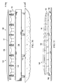
- the disclosed embodiments provide a method and apparatus for fabricating a stiffened composite panel, such as a stiffened wing skin panel 48.
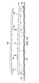
- the wing skin panel 48 may include one or more contoured areas 55 in the chord-wise direction 56 and/or the span-wise direction 54.
- the wing skin panel 48 comprises a composite wing skin 50 which may be a composite laminate, such as fiber reinforced epoxy, or a sandwich construction having a core (not shown) sandwiched between inner and outer composite laminate skins.
- the composite wing skin 50 is strengthened and stiffened by a plurality of composite laminate stiffeners 52 which are arranged generally parallel to each other and extend in the span-wise direction 54 of the wing skin panel 48.
- the spacing between the stiffeners 52 in the chord-wise direction 56 of the wing skin panel 48 may vary with the application.
- the wing skin panel 48 may include one or more contoured areas 55 in the chord-wise direction 56 and/or the span-wise direction 54.
- the composite laminate stiffeners 52 conform along their lengths to contours or other local features or attributes of the wing skin 50.
- the composite laminate stiffeners 52 may be bonded to, or co-cured with the wing skin 50.
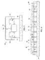
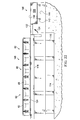
- the stiffeners 52 are blade type stringers having a channel-like, generally C-shaped cross-section, however the stiffeners 52 may have other cross-sectional shapes with one or more legs that transfer wing loads.
- the wing skin panel 48 may employ a combination of stingers or other stiffeners 52 that have differing cross sectional geometries in order to meet specific wing load requirements. Although a wing skin panel 48 is shown, the disclosed method and apparatus may be employed to fabricate other types of stiffened panels used in a variety of applications.
- a stiffener forming cell 68 includes a plurality of individual forming block modules 58 used to layup and separately form composite pre-preg (not shown) into the desired stiffener shapes.
- each of the forming block modules 58 comprises a plurality of configurable forming block segments (not shown in Figure 4 ) that may be respectively assembled and adjusted to locally form the pre-preg into the desired stiffener shape.
- the stiffeners 52 are removed from the forming block modules 58 and transferred 66 to cure tool modules 60 that are used to support and maintain the shape of the stiffeners 52 during curing.
- Each of the cure tool modules 60 comprises a plurality of configurable cure tool segments (not shown in Figure 4 ) that may be respectively assembled and adjusted to support local portions of the stiffener 32 during the curing process.
- the stiffeners 52 are assembled into a stiffener assembly 62 by transferring the cure tool modules 60 to a stiffener assembly cell 82 where the cure tool modules 60 are assembled in indexed relationship to each other into a cure tool assembly 62.
- the cure tool assembly 62 and stiffener assembly 148 are then transferred to a final assembly cell 146 where the composite skin 50 is placed on the stiffener assembly 42.
- a caul plate (not shown in Figure 4 ) may be placed over the composite skin 50, following which the composite skin 50 and the stiffener assembly 148 are vacuum bagged and then cured in an oven or an autoclave (not shown).
- the tooling used to form and cure the stiffener 52 is modular, allowing multiple individual stiffeners 52 to be formed and readied for curing in parallel. Furthermore, the amount of tooling required is reduced because both the forming block modules 58 and the cure tool modules 60 may be re-configured to fabricate stiffeners 52 having different lengths, contours, cross-sectional shapes and local attributes. Moreover, where a wing skin panel 48 employs stiffeners 52 having two or more differing cross sectional geometries, the forming block modules 58 and the cure tool modules 60 may be configured and mixed as required.
- the forming cell 68 includes a plurality of forming block modules 58 that may be individually configured to form stiffeners 52 to the desired length, contour and/or cross-sectional shape.
- Each of the forming block modules 58 comprises a plurality of forming block segments 70, co-linearly arranged end-to-end, as best seen in Figure 6 .
- Each of the forming block segments 70 may be formed of any suitable material, such as without limitation, machined carbon fiber reinforced plastic, and possesses all of the tool surfaces required to form local attributes of a stiffener 52.
- a stiffener 52 in the form of a blade stringer having a C-shaped cross-section is formed using forming block segments 70 each having three contiguous tool surfaces 70a, 70b, 70c onto which composite pre-preg may be formed using hand layup or automated techniques.
- Each of the forming block segments 70 is supported on a standoff 72 which in turn is adjustably mounted 80 on a support assembly 76 resting on a factory floor 81 or other surface.
- the forming block segments 70 may be fastened to the standoffs 72 by any suitable means, such as by fasteners 74.
- Bolted assemblies (not shown) or other mechanisms may be used to mount standoffs 72 in a desired position on a support assembly 76, thereby permitting adjustment of the height of the standoffs 72, and thus of the position of the forming block segments 70. In some embodiments, it may also be possible to adjust the position of the forming block segments 70 on the standoffs 72.
- the forming block segments 70 have been adjusted on the support assembly to form a contour 78 substantially matching the contour 55 ( Figure 3 ) of the wing skin at particular locations on the stiffeners 52.
- the forming block segments 70 may contain forming features and/or be adjusted to form other local attributes of the stiffeners 52, such as ply doublers, jogs, etc. in either the wing skin 50 or the stiffeners 52.
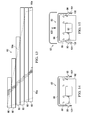
- the number of forming block segments 70 in each of the forming block modules 58 may depend on the length of the particular stiffeners 52 being formed. For example, referring to Figure 7 , six forming block modules 58 of differing lengths are needed to form stiffeners 52 that extend along the entire length of the wing skin 50 (shown by the skin outline 50a) at different locations in the cord-wise direction 56 ( Figure 1 ) of the wing skin panel 48. In order to form stiffeners 52 for a wing skin panel having a different outline shape or length, forming block segments 70 may be simply removed or added to the individual forming block modules 58, as required.
- FIGs 8, 9 and 10 sequentially illustrate a stiffener 52 being formed onto one of the forming block modules 58.
- Composite pre-preg is laid up 84 either one ply at a time, or as a sub-laminate 83 comprising two or more plies, according to a predetermined ply schedule which dictates the number of plies and their fiber orientations.
- a ply or sub-laminate 83 is laid up 84, the edges 83a of the pre-preg plies are formed down onto flange surfaces 70a, 70b ( Figure 8 ) of the forming block module 58.
- Plies or sub-laminates 83 are laid up 84 in this manner until the entire thickness of the stiffener 52 has been formed.
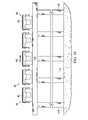
- the cure tool module 60 comprises a plurality of cure tool segments 88 co-linearly arranged as best seen in Figure 12 .
- Each of the cure tool segments 88 is mounted on standoffs 92 which are adjustably supported on a support assembly 96 resting on a factory floor 81 or other supporting surface.
- the standoffs 92 are slidable 85 on the support assembly 96, thereby permitting each of the cure tool segments 88 to be adjusted in position to match local surfaces of a stiffener 52 that has been formed on one of the forming block modules 58.
- Each of the cure tool modules 60 includes lateral ribs 90 whose purpose will be described later. Similar to the previously described forming block modules 58, the cure tool segments 88 are configured to form cure tool modules 60 of the lengths corresponding to the stiffeners 52 that are needed to cover a wing skin 50, an outline 50a of which is shown in Figure 13 overlaid on cure tool modules 60 of various lengths.
- Each of the cure tool modules 60 may further include integral vacuum lines 94 that are adapted to be coupled with a vacuum source (not shown) whose function will be discussed later.
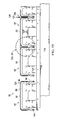
- a vacuum bag segment 98 is placed over each of the cure tool modules 60 and is sealed thereto by sealing tape 102 or a similar suitable sealant.
- the vacuum bag segments 98 are made of substantially flexible conventional material, and may be reusable or non-reusable. After the vacuum bag segment 98 has been installed as shown in Figure 14 , the vacuum bag segment 98 is drawn down tightly against the cure tool module 60 by evacuating the vacuum bag segment 98 using the integral vacuum lines 94 within the cure tool module 60 shown in figure 11 .
- seals 104 which may comprise a suitable sealant tape, are placed along the bottom edges of the vacuum bag segment 98 overlying the sealing tape 102 and extending along the entire length of the vacuum bag segment 98.
- Figures 16 , 17 and 18 illustrate a method of transferring the cure tool modules 60 to the stiffener assembly cell 82.
- a bridge 108 that is pivotably mounted on the support assembly 96 is swung 110 into registration with an elevated cure tool assembly table 118 at the stiffener assembly cell 82.
- the elevated cure tool assembly table 118 may comprise a series of cross beams mounted on be supports 116 that mount the cross beams above a factory floor or other surface 114 at a height 112 that allows workers to access the area beneath the cure tool modules 60.
- the cure tool modules 60 may be slid 106 across the bridge 108 onto the cure tool assembly table 118, following which the bridge 108 may be lowered, and another support assembly 96 having a cure tool module 60 mounted thereon is transported to the stiffener assembly cell 182 in preparation for moving the next cure tool module 60 onto the cure tool assembly table 118.
- the cure tool modules 60 may be placed and assembled as a group on the elevated cure tool assembly table 118, following which the stiffeners 52 may be transferred one-by-one to the awaiting cure tool modules 60, thereby eliminating the need for transferring the stiffeners 52 from the individual support assemblies 96.
- the cure tool modules 60 are slid toward each other into an a preselected, indexed position.
- the indexed position of the cure tool modules 60 is maintained by installing a locking bar 124 which holds the cure tool modules 60 together as a single cure tool assembly 62.
- the locking bar 124 is releasably attached to each of the cure tool modules 60 by any suitable means, such as clamps or releasable fasteners.
- the ribs 90 may assist in holding the vacuum bag segments 98, and may assist in stabilizing/isolating the seals 102, 104.
- a radius groove 126 may be formed between adjacent stiffeners 52.
- the radius groove 126 may be filled using a filler or "noodle" 128 which may comprise, for example and without limitation, a folded film adhesive or a pre-preg.
- Figure 21 illustrates an indexed cure tool assembly 62 having a completed stiffener assembly 148 thereon.
- Figure 21 also illustrates a swingable bridge 132 pivotably mounted on one end of the cure tool assembly table 118.
- Figures 22-25 illustrate the steps involved in transferring the cure tool assembly 62 and stiffener assembly 148 from the stiffener assembly cell 82 to the final assembly cell 146.
- the bridge 132 on cure tool assembly table 118 is pivoted to its raised position, registering with a supporting surface 138 on a cure rack 136 forming part of the final assembly cell 146.
- the cure rack 136 is mounted on rails 142 for sliding movement over a supporting surface 144.
- the cure tool assembly 62 and stiffener assembly 148 may be slid across the cure tool assembly table 118 and bridge 132 onto the cure rack 136, as illustrated in Figures 23-25 .
- the cure rack 136 may be moved along rails 142 to a position in proximity to a manipulator 150 used to place a composite skin 50 onto the stiffener assembly 148.
- the manipulator 150 may comprise any suitable automation equipment which may include suction cups 152, or other suitable holding means for releasably holding the skin 50 as the manipulator 150 places 154 it onto the stiffener assembly 148.
- the manipulator 150 may be used to place the skin 50 onto the stiffener assembly 148 while the stiffener assembly 148 is on the elevated assembly table 118, as shown in figure 21 , prior to being transferred to the final assembly cell 146.
- a caul plate 156 is placed onto the skin 50 in preparation for bagging and curing the wing skin panel 50.
- vacuum bagging of the wing skin panel 50 is completed by sealing the periphery of the vacuum bag segments 98 against the caul plate 156 using a suitable sealant 160.
- the applied vacuum is reversed (see Figure 33 ), or rather it is released, by releasing the vacuum within the cure tool modules 60 that previously held the vacuum bag segments 98 against the cure tool modules and 60, and evacuating the volume within the vacuum bag surrounding the stiffener assembly 148 and the skin 50.
- the bagging material is initial vacuum sealed to the individual modules during the lamination/forming of the stiffener elements. Once the stiffeners are assembled together and the skin is installed the same bagging material is then sealed against the caul plate (on top of the skin) and a vacuum is pulled on the skin/stiffener assembly for cure. So the vacuum is initially pulling bagging onto module tooling and then is pulled onto caul plate for cure. Conventional vacuum ports can be used for either case.
- the cure rack 136 along with the cure tool assembly 62 and stiffener assembly 148 can be moved into an oven or autoclave (not shown) where the stiffener assembly 148 is cured.
- the caul plate 156 is removed 162, and the cured stiffener assembly 148 is the lifted away from the cure tool assembly 62.
- the vacuum bagging material may then be removed from the cured stiffener assembly 148 by pulling or cutting it away.
- the seals 102 remain attached to and are lifted away with the vacuum bag segments 98.
- the cure rack 136 may be slid into proximity to the elevated cure tool assembly table 118, and the bridge 132 is swung into position to allow the cure tool assembly 62 to be slid 172 from the cure rack 136 back onto the table in readiness to receive the next set of stiffeners 52.
- Figure 36 broadly illustrates the steps of a method of fabricating a stiffened composite panel, such as the wing skin panel 48 previously described.
- a plurality of individual forming block modules 58 is assembled, for example side-by-side.
- the individual forming block modules 58 are assembled by arranging individual forming block segments 70 co-linearly as shown at step 176, and adjusting the individual forming block segments 70 to match a desired skin contour or other skin attributes, at step 178.
- the composite stiffeners 52 are formed on the individual forming block modules 58 by laying up composite pre-preg over the forming block modules 58.
- a plurality of cure tool modules 60 is assembled by arranging the cure tool modules segments 88 co-linearly at step 184, and adjusting the individual cure tool segments 88 at 184 to match the skin contour or other skin attributes.
- vacuum bag segments 98 are installed on each of the cure tool modules 60 and sealed thereagainst.
- the stiffeners 52 are assembled into a stiffener assembly 148 by placing the cure tool modules 60 side-by-side, and locking them together in indexed relationship to each other.
- the vacuum bag segments 98 are then connected together using seals 104 or by welding them together at step 192.
- Radius fillers or noodles 128 may be installed in radius grooves 126 between the stiffeners 52, as required, in step 194.
- a composite skin 50 is placed on the stiffener assembly 148.
- a caul plate 156 is then installed over the skin 50 at step 198.
- the composite skin surface is vacuum bagged, and the assembled stiffener assembly 148 and skin 50 are then cured in an autoclave or oven at step 202.
- the caul plate 156 is lifted away, and the wing skin panel 48 is de-bagged either by pulling or cutting away the bagging material.
- the assembled cure tool modules 60 are unlocked and may then returned directly to production, in preparation for assembling the next set of the stiffeners 52 by transferring the cure tool modules 60 back to the elevated cure tool assembly table 118.
- the vacuum bag segments 98 which cover the individual cure tool modules 60, it may not be necessary to clean the cure tool modules 60 before they are returned to production, thus speeding up the production process by allowing quick turnaround of tooling and reducing downtime.
- Embodiments of the disclosure may find use in a variety of potential applications, particularly in the transportation industry, including for example, aerospace, marine, automotive applications and other application where stiffened composite panels may be used.
- Aircraft applications of the disclosed embodiments may include, for example, without limitation, wings, horizontal stabilizers and vertical stabilizers, to name only a few.
- exemplary method 204 may include specification and design 208 of the aircraft 206 and material procurement 210.
- component and subassembly manufacturing 212 and system integration 214 of the aircraft 206 takes place. Thereafter, the aircraft 204 may go through certification and delivery 216 in order to be placed in service 218. While in service by a customer, the aircraft 206 is scheduled for routine maintenance and service 220, which may also include modification, reconfiguration, refurbishment, and so on.
- a system integrator may include without limitation any number of aircraft manufacturers and major-system subcontractors; a third party may include without limitation any number of vendors, subcontractors, and suppliers; and an operator may be an airline, leasing company, military entity, service organization, and so on.
- the aircraft 206 produced by exemplary method 204 may include an airframe 222 with a plurality of systems 224 and an interior 226.
- high-level systems 224 include one or more of a propulsion system 228, an electrical system 230, a hydraulic system 232, and an environmental system 234. Any number of other systems may be included.
- an aerospace example is shown, the principles of the disclosure may be applied to other industries, such as the marine and automotive industries.
- Systems and methods embodied herein may be employed during any one or more of the stages of the production and service method 204.
- components or subassemblies corresponding to production process 212 may be fabricated or manufactured in a manner similar to components or subassemblies produced while the aircraft 206 is in service.
- one or more apparatus embodiments, method embodiments, or a combination thereof may be utilized during the production stages 212 and 214, for example, by substantially expediting assembly of or reducing the cost of an aircraft 206.
- apparatus embodiments, method embodiments, or a combination thereof may be utilized while the aircraft 206 is in service, for example and without limitation, to maintenance and service 220.
Abstract
Description
- The present disclosure generally relates to the fabrication of stiffened composite panels, and, in at least certain embodiments, deals more particularly with a method and apparatus for forming, assembling and curing stiffened skins using configurable modular tooling.
- In order to strengthen and stiffen composite panels such as aircraft wing skins, the panels may incorporate composite stiffeners. For example, aircraft composite wing skins may be stiffened with composite stringers that extend in the span-wise direction of the wing and are attached to the skin by bonding or co-curing techniques.
- Existing tooling used to cure stiffened skins is typically large, heavy and expensive to fabricate. The skins are laid up directly on the cure tool along with the stringers and then vacuum bagged. The placement and assembly of the stringers, skin, bagging and related items are performed serially, resulting in relatively long work-in-process (WIP) flow times. Because of these long flow times, multiple identical tool sets may be required to achieve desired production rates. These additional tool sets increase both capital costs and factory floor space requirements. Furthermore, additional cure tooling and associated special tools are also typically required to layup, handle, protect and accurately index the stringers when they are being installed on a skin. These additional tools may also be large and expensive, further adding to capital costs, tooling lead times and floor space requirements.
- Another problem with existing tooling is related to the need to install vacuum bagging over the stringers and skin after they have been laid up. This requires that the panel be fully assembled before bagging can be installed, consequently bagging flow time becomes part of the critical production path and can also cause delays.
- Accordingly, there is a need for a method and apparatus for fabricating stiffened composite panels, such as wing skin panels, that reduce tooling and related floor space requirements, and which increases production flow rates.
- The disclosed embodiments provide a method and apparatus for fabricating stiffened composite panels, such as aircraft wing skins, which reduce tooling costs, assembly floor space requirements and WIP flow times. In embodiments, modular tools are used which allow layup, forming, bonding, and bagging processes to be performed in parallel, rather than in series with each other. Smaller, simpler fabrication tooling reduces capital costs and provides production flexibility. Each of the modular tools may comprise co-linearly arranged individual segments that control part-specific attributes such as size and/or shape and/or geometry and/or contours and/or jogs, etc. during layup, forming and curing. The tool segments may be reconfigurable to permit layup and curing of parts having differing sizes and/or shapes and/or geometries and/or contours and other attributes, or to quickly carry out engineering changes to stiffeners. The tools are relatively lightweight, which may reduce cure times.
- In general, in embodiments, apparatus and/or methods are provided in which a plurality of forming block modules are provided, each comprising a plurality of forming block segments. The segments in each forming block module may be arranged substantially co-linearly. Each forming block segment may be individually adjustable, and optionally adjusted, to form desired local geometry or other attribute of a composite part, such as a laminate stiffener, to be formed on the respective module comprising those segments. Each forming block module may be arranged for and/or used to form a respective composite part, such as a respective laminate stiffener. A plurality of cure tool modules may be provided, each comprising a plurality of cure tool segments. The segments in each cure tool module may be arranged substantially co-linearly. In each cure tool module, the cure tool segments may be individually adjustable, and optionally adjusted, to match the desired local geometry or other attribute of a respective one of the composite parts previously formed. Each cure tool module may be provided with at least one respective vacuum bag segment. Each vacuum bag segment may be sealed to one of the cure tool modules. Vacuum bag segments provided to adjacent cure tool modules may be sealed to each other to form a vacuum bag. Peripheral ends of the vacuum bag may be sealed to cure tool modules. The formed composite parts may be transferred from the forming block modules to the cure tool modules. Air in the space between the vacuum bag segments and the cure tool modules may be evacuated. This may be done before the composite parts are transferred to the cure tool modules. A composite skin may be placed on the composite parts when they are on the cure tool modules. A caul plate may be placed on the composite skin. The peripheral ends of the vacuum bag may be sealed to the caul plate. Pressurised fluid, such as air, may be introduced between the cure tool modules and the vacuum bag. The composite skin and the composite parts may then be cured.
- By providing a plurality of modules in this way, composite parts, such as stiffeners, may be formed in parallel rather than in series. It will be understood that others of the features may also contribute to this. By providing individual vacuum bag segments, and by fitting these to cure tool modules that are separate from the forming block modules, the preparation of the bagging on the cure tool modules can be done in parallel with lay-up of the composite part on the forming block modules.
- According to one aspect, there is provided apparatus as defined in
claim 1 of the appended claims. The composite panel may be a composite wing panel. - According to another aspect, there is provided a method as defined in
claim 7. The composite skin may be a composite wing skin. - According to one disclosed embodiment, apparatus is provided for fabricating composite laminate parts. The apparatus comprises at least one forming block module adapted to have a composite laminate formed thereon. The forming block module including a plurality of forming block segments co-linearly arranged and each adapted for forming local attributes of the composite laminate. The apparatus may further comprise a support assembly for supporting and adjusting a position of each of the forming block segments. The forming block segments are removably mounted on the support assembly allowing assembly of a forming block module of a desired length. Each of the forming block segments is slidably adjustable on the support assembly. The forming block module is elongate and includes a forming surface contoured along its length. The apparatus may further comprise at least one cure tool module adapted to have a formed composite laminate cured thereon, the cure tool module including a plurality of cure tool segments co-linearly arranged and each adapted to maintain the shape of local features of the formed composite laminate during curing. Each of the cure tool segments includes vacuum lines adapted for drawing a vacuum bag down against the cure tool segments.
- According to another disclosed embodiment, apparatus is provided for fabricating composite laminate stiffeners. The apparatus comprises a plurality of individual forming block modules on which composite pre-preg may be formed into composite laminate stiffeners, each of the forming block modules being elongate and configurable along its length to form any of multiple attributes of a composite laminate stiffener. The apparatus also includes a plurality of cure tool modules on which the composite laminate stiffeners may be cured, each of the cure tool modules being elongate and configurable along its length to substantially match the composite laminate stiffeners formed on the forming block modules. Each of the individual forming block modules includes a plurality of forming block segments arranged co-linearly. The apparatus further comprises a locking device for holding and locking the cure tool modules in indexed relationship to each other. Each of the cure tool modules includes a plurality of cure tool segments arranged co-linearly. The apparatus further comprises a vacuum bag for compacting each of the composite laminate stiffeners. The vacuum bag includes a plurality of separate vacuum bag segments respectively sealed over the cure tool module segments. The vacuum bag segments are sealed together. Each of the cure tool segments includes integral vacuum lines adapted to be coupled with a vacuum source for drawing a vacuum in the vacuum bag.
- According to still another embodiment, apparatus is provided for fabricating a stiffened composite wing skin panel. The apparatus comprises a forming cell including a plurality of individual forming block modules on which composite pre-preg may be separately formed into composite laminate stiffeners, and a plurality of individual cure tool modules on which the composite laminate stiffeners may be placed and cured. The Apparatus also includes a stiffener assembly cell in which the cure tool modules each having a composite laminate stiffener placed thereon may be assembled together and held in indexed relationship to each other, and a final assembly cell in which a composite skin is placed on the composite laminate stiffeners in readiness for curing. The apparatus may further comprise a vacuum bag for compacting the composite skin and the composite laminate stiffeners. The vacuum bag includes a plurality of individual vacuum bag segments respectively associated with and sealed to the cure tool modules. Each of the individual forming block modules includes a plurality of forming block segments arranged co-linearly and adjustable for forming desired local attributes of one of the composite laminate stiffeners. Each of the cure tool modules includes a plurality of cure tool segments arranged co-linearly and adjustable in position to match local attributes of one of the composite laminate stiffeners. The cure tool modules are slidable from the stiffener assembly cell to the final assembly cell.
- According to a further embodiment, a method is provided of fabricating composite stiffeners. The method comprises assembling at least one forming block module by co-linearly arranging a plurality of forming block segments each adapted for forming a local attribute of a composite stiffener, and forming a composite stiffener by forming composite pre-preg over the forming block. The method also comprises transferring the formed composite stiffener to a cure tool, and curing the formed composite stiffener on the cure tool. The method may further comprise assembling the cure tool by co-linearly arranging a plurality of cure tool segments, each shaped and positioned to match local attributes of the formed composite stiffener.
- According to still another embodiment, a method is provided of fabricating a stiffened composite wing skin. The method comprises assembling each of a plurality of forming block modules, including, co-linearly arranging and adjusting a plurality of forming block segments,
producing stiffeners by forming composite pre-preg over each of the forming block modules, and assembling each of a plurality of cure tool modules on which the stiffeners may be cured, including co-linearly arranging and adjusting a plurality of cure tool segments to match the geometry of the stiffeners, The method further comprises transferring the stiffeners from the forming block modules to the cure tool modules, assembling a plurality of the stiffeners by placing the cure tool modules side-by-side, placing a composite skin on the plurality of the assembled stiffeners, and curing the composite skin and the assembled stiffeners. The method may include vacuum bagging the assembled stiffeners and the skin, including sealing vacuum bag segments respectively over the cure tool modules, and drawing the vacuum bag segments down against the cure tool modules using vacuum lines on the cure tool modules to evacuate the vacuum bag segments. - According to a further embodiment, a method is provided of fabricating a stiffened composite wing skin, comprising assembling a plurality of cure tool modules each adapted to have a composite stiffener placed thereon, and individually vacuum bagging the cure tool modules using vacuum bag segments. The method also comprises sealing the vacuum bag segments together, placing a composite skin over the composite stiffeners, placing a caul plate over the composite skin, and sealing the vacuum bag segments to the caul plate. The method further comprises drawing the vacuum bag segments respectively down against cure tool modules before the composite stiffeners are respectively placed on the cure tool modules. The method may also comprise curing the composite stiffeners and the skin, removing the vacuum bag segments from the cure tool modules, and returning the cure tool modules to production.
- According to still a further embodiment, a method is provided of fabricating a stiffened composite wing skin, comprising forming a plurality of composite stiffeners respectively on individual forming tools, transferring the formed composite stiffeners respectively to cure tools, and assembling the composite stiffeners by assembling the cure tools together. The method further comprises placing a composite skin on the assembled composite stiffeners, and curing the composite skin and the assembled composite stiffeners. The method may also comprise removing the cured composite skin and cured composite stiffeners from the assembled cure tools, disassembling the cure tools, and returning the cure tools to production for curing additional composite stiffeners.
- Further, the disclosure comprises embodiments according to the following clauses, numbered for clarity:
-
Clause 1. Apparatus for fabricating composite laminate parts, comprising:- at least one forming block module adapted to have a composite laminate formed thereon, the forming block module including a plurality of forming block segments co-linearly arranged and each adapted for forming local attributes of the composite laminate.
-
Clause 2. The apparatus ofclause 1, further comprising a support assembly for supporting and adjusting a position of each of the forming block segments. -
Clause 3. The apparatus ofclause 2, wherein the forming block segments are removably mounted on the support assembly allowing assembly of a forming block module of a desired length. -
Clause 4. The apparatus ofclause 2, wherein each of the forming block segments is slidably adjustable on the support assembly. - Clause 5. The apparatus of
clause 1, wherein the forming block module is elongate and includes a forming surface contoured along the length of the forming block module. - Clause 6. The apparatus of
clause 1, further comprising;
at least one cure tool module adapted to have a formed composite laminate cured thereon, the cure tool module including a plurality of cure tool segments co-linearly arranged and each adapted to maintain the shape of local features of the formed composite laminate during curing. -
Clause 7. The apparatus of clause 6, wherein each of the cure tool segments includes vacuum lines adapted for drawing a vacuum bag down against the cure tool segments. - Clause 8. Apparatus for fabricating composite laminate stiffeners, comprising:
- a plurality of individual forming block modules on which composite pre-preg may be formed into composite laminate stiffeners, each of the forming block modules being elongate and configurable along its length to form any of multiple attributes of a composite laminate stiffener; and
- a plurality of cure tool modules on which the composite laminate stiffeners may be cured, each of the cure tool modules being elongate and configurable along its length to substantially match the composite laminate stiffeners formed on the forming block modules.
- Clause 9. The apparatus of clause 8, wherein each of the individual forming block modules includes a plurality of forming block segments arranged co-linearly.
- Clause 10. The apparatus of clause 8, further comprising:
- a holder for holding the cure tool modules in indexed relationship to each other.
- Clause 11. The apparatus of clause 8, wherein each of the cure tool modules includes a plurality of cure tool segments arranged co-linearly.
- Clause 12. The apparatus of clause 11, further comprising a vacuum bag for compacting each of the composite laminate stiffeners, the vacuum bag including a plurality of separate vacuum bag segments respectively sealed over the cure tool segments.
- Clause 13. The apparatus of clause 12, wherein the vacuum bag segments are sealed together.
- Clause 14. The apparatus of clause 12, wherein each of the cure tool segments includes integral vacuum lines adapted to be coupled with a vacuum source for drawing a vacuum in the vacuum bag.
- Clause 15. Apparatus for fabricating a stiffened composite wing panel, comprising:
- a forming cell including a plurality of individual forming block modules on which composite pre-preg may be separately formed into composite laminate stiffeners;
- a plurality of individual cure tool modules on which the composite laminate stiffeners may be placed and cured;
- a stiffener assembly cell in which the cure tool modules each having a composite laminate stiffener placed thereon may be assembled together and held in indexed relationship to each other; and,
- final assembly cell in which a composite skin is placed on the composite laminate stiffeners in readiness for curing.
-
Clause 16. The apparatus of clause 15, further comprising:- a vacuum bag for compacting the composite skin and the composite laminate stiffeners, the vacuum bag including a plurality of individual vacuum bag segments respectively associated with and sealed to the cure tool modules.
- Clause 17. The apparatus of clause 15, wherein each of the individual forming block modules includes a plurality of forming block segments arranged co-linearly and adjustable for forming desired local attributes of one of the composite laminate stiffeners.
- Clause 18. The apparatus of clause 15, wherein each of the cure tool modules includes a plurality of cure tool segments arranged co-linearly and adjustable in position to match local attributes of one of the composite laminate stiffeners.
- Clause 19. Apparatus of clause 15, wherein the cure tool modules are slidable from the stiffener assembly cell to the final assembly cell.
- Clause 20. A method of fabricating composite stiffeners, comprising:
- assembling at least one forming block module by co-linearly arranging a plurality of forming block segments each adapted for forming a local attribute of a composite stiffener;
- forming a composite stiffener by forming composite pre-preg over the forming block;
- transferring the formed composite stiffener to a cure tool; and
- curing the formed composite stiffener on the cure tool.
- Clause 21. The method of clause 20, further comprising:
- assembling the cure tool by co-linearly arranging a plurality of cure tool segments each shaped and positioned to match local attributes of the formed composite stiffener.
- Clause 22. A method of fabricating a stiffened composite wing skin, comprising:
- assembling each of a plurality of forming block modules, including, co-linearly arranging and adjusting a plurality of forming block segments;
- producing stiffeners by forming composite pre-preg over each of the forming block modules;
- assembling each of a plurality of cure tool modules on which the stiffeners may be cured, including co-linearly arranging and adjusting a plurality of cure tool segments to match the geometry of the stiffeners;
- transferring the stiffeners from the forming block modules to the cure tool modules:
- assembling a plurality of the stiffeners by placing the cure tool modules side-by-side;
- placing a composite skin on the plurality of the assembled stiffeners; and,
- curing the composite skin and the assembled stiffeners.
- Clause 23. The method of clause 22, further comprising:
- vacuum bagging the assembled stiffeners and the skin, including sealing vacuum bag segments respectively over the cure tool modules.
- Clause 24. The method of clause 23, further comprising:
- drawing the vacuum bag segments down against the cure tool modules using vacuum lines on the cure tool modules to evacuate the vacuum bag segments.
-
Clause 25. The method of clause 22, wherein the composite skin is contoured, and co-linearly arranging and adjusting the forming block segments includes adjusting the forming block segments to substantially match the contour of the composite skin. - Clause 26. A method of fabricating a stiffened composite wing skin, comprising:
- assembling a plurality of cure tool modules each adapted to have a composite stiffener placed thereon;
- individually vacuum bagging the cure tool modules using vacuum bag segments;
- sealing the vacuum bag segments together;
- placing a composite skin over the composite stiffeners;
- placing a caul plate over the composite skin; and,
- sealing the vacuum bag segments to the caul plate.
-
Clause 27. The method of clause 26, further comprising:- drawing the vacuum bag segments respectively down against cure tool modules before the composite stiffeners are respectively placed on the cure tool modules.
- Clause 28. The method of clause 26, further comprising:
- curing the composite stiffeners and the skin;
- removing the vacuum bag segments from the cure tool modules; and,
- returning the cure tool modules to production.
- Clause 29. A method of fabricating a stiffened composite wing skin, comprising:
- forming a plurality of composite stiffeners respectively on individual forming tools;
- transferring the formed composite stiffeners respectively to cure tools;
- assembling the composite stiffeners by assembling the cure tools together;
- placing a composite skin on the assembled composite stiffeners; and
- curing the composite skin and the assembled composite stiffeners.
- Clause 30. The method of clause 29, further comprising:
- removing the cured composite skin and cured composite stiffeners from the assembled cure tools;
- disassembling the cure tools; and
- returning the cure tools to production for curing additional composite stiffeners.
- It is envisaged that, unless there is a technical incompatibility that prevents it, optional features of any embodiment may also be optional features of any other embodiment; and that optional features may be combined in any workable combination.
- The features, functions, and advantages can be achieved independently in various embodiments of the present disclosure or may be combined in yet other embodiments in which further details can be seen with reference to the following description and drawings.
- Illustrative embodiments, as well as a preferred mode of use, further objectives and advantages thereof, will best be understood by reference to the following detailed description of an illustrative embodiment of the present disclosure when read in conjunction with the accompanying drawings, wherein:
-
Figure 1 is illustration of a plan view of a stiffened composite wing skin panel fabricated in accordance with the disclosed method and apparatus. -
Figure 2 is an illustration of a sectional view taken along the line 2-2 inFigure 1 , contours of the panel not shown. -
Figure 3 is an illustration of a view in the direction designated asFIG. 3 inFigure 1 , illustrating contour of the wing skin panel. -
Figure 4 is an illustration of a simplified block diagram of apparatus for fabricating the wing skin panel shown inFigure 1 . -
Figure 5 is an illustration of an end view of one of the forming block modules shown inFigure 4 . -
Figure 6 is an illustration of a longitudinal side view of a forming cell showing individual forming block segments of one of the forming block modules. -
Figure 7 is an illustration of a plan view showing the lengths of forming blocks modules required to form stiffeners used in wing skin panel shown inFigure 1 , the general outline of the wing skin shown in the phantom. -
Figure 8 is an illustration of a view similar toFigure 5 , but showing a sub-laminate being placed on the forming block module. -
Figure 9 is an illustration similar toFigure 8 but showing the edges of the sub-laminate being formed down onto the forming block module. -
Figure 10 is an illustration similar toFigure 9 but showing a formed stiffener being lifted away from the forming block module. -
Figure 11 is an illustration of an end view of one of the cure tool modules shown inFigure 4 . -
Figure 12 is an illustration of a longitudinal side view of the cure tool module shown inFigure 11 adjustably mounted on supports and showing the individual cure tool segments. -
Figure 13 is an illustration of a plan view showing the lengths cure tool modules required to form stiffeners used in the wing skin panel shown inFigure 1 , the general outline of the wing skin shown in the phantom -
Figure 14 is an illustration similar toFigure 11 , but showing a vacuum bag segment sealed over the cure tool module. -
Figure 15 is an illustration similar toFigure 14 but showing a formed laminate stiffener being placed onto the cure tool module, over a vacuum bag segment. -
Figure 16 is an illustration of an end view showing how the cure tool modules are transferred to a stiffener assembly cell. -
Figure 17 is an illustration of a longitudinal side view of the stiffener assembly cell. -
Figure 18 is an illustration of an end view of the stiffener assembly cell shown inFigure 17 . -
Figure 19 is an illustration of an enlarged end view showing several of the cure tool modules locked together, wherein a filler noodle is about to be installed between adjacent stiffener layups. -
Figure 20 is an illustration of the area designated asFigure 20 inFigure 19 , better showing the vacuum bag seals. -
Figure 21 is illustration of an end view of the stiffener assembly cell, showing the assembled stiffeners on cure tool modules that have been locked and indexed together. -
Figure 22 is an illustration similar toFigure 21 but also illustrating a final assembly cell. -
Figure 23 is an illustration similar toFigure 22 but showing the stiffener assembly having been partially transferred to the final assembly cell. -
Figure 24 is an illustration of an end view showing the stiffener assembly having been transferred onto a cure rack in the final assembly cell. -
Figure 25 is an illustration of a view in the direction designated asFIG. 25 inFigure 24 . -
Figure 26 is an illustration of an end view similar toFigure 24 , but showing a wing skin being placed onto the stiffener assembly. -
Figure 27 is an illustration of a view in the direction designated asFIG. 27 inFigure 26 . -
Figure 28 is an illustration showing the wing skin having been placed on the stiffener assembly, and a caul plate about to be installed over the wing skin. -
Figure 29 is an illustration of a view in the direction designated asFIG. 29 inFigure 28 . -
Figure 30 is an illustration of an end view showing the caul plate having been installed onto the wing skin. -
Figure 31 is an illustration of a view in the direction designated asFIG. 31 inFigure 30 . -
Figure 32 is an illustration of an end view of the final assembly cell, showing how the assembled vacuum bag segments are sealed to the caul plate. -
Figure 33 is an illustration similar toFigure 32 but showing the vacuum bag having been evacuated in preparation for a curing operation. -
Figure 34 is an illustration of an end view of the stiffener assembly and caul plate being removed from the cure tool assembly. -
Figure 35 is an illustration of an end view showing the cured tool assembly being returned to production. -
Figure 36 is an illustration of a flow diagram of a method of fabricating a stiffened composite wing skin panel using modular tool components. -
Figure 37 is an illustration of a flow diagram of aircraft production and service methodology. -
Figure 38 is illustration of a block diagram of an aircraft. - Referring first to
Figures 1, 2 and 3 , the disclosed embodiments provide a method and apparatus for fabricating a stiffened composite panel, such as a stiffenedwing skin panel 48. Thewing skin panel 48 may include one or morecontoured areas 55 in thechord-wise direction 56 and/or thespan-wise direction 54. Thewing skin panel 48 comprises acomposite wing skin 50 which may be a composite laminate, such as fiber reinforced epoxy, or a sandwich construction having a core (not shown) sandwiched between inner and outer composite laminate skins. - The
composite wing skin 50 is strengthened and stiffened by a plurality ofcomposite laminate stiffeners 52 which are arranged generally parallel to each other and extend in thespan-wise direction 54 of thewing skin panel 48. The spacing between thestiffeners 52 in thechord-wise direction 56 of thewing skin panel 48 may vary with the application. Thewing skin panel 48 may include one or morecontoured areas 55 in thechord-wise direction 56 and/or thespan-wise direction 54. Thecomposite laminate stiffeners 52 conform along their lengths to contours or other local features or attributes of thewing skin 50. Depending upon the application, thecomposite laminate stiffeners 52 may be bonded to, or co-cured with thewing skin 50. In the illustrated embodiment, thestiffeners 52 are blade type stringers having a channel-like, generally C-shaped cross-section, however thestiffeners 52 may have other cross-sectional shapes with one or more legs that transfer wing loads. In some cases, thewing skin panel 48 may employ a combination of stingers orother stiffeners 52 that have differing cross sectional geometries in order to meet specific wing load requirements. Although awing skin panel 48 is shown, the disclosed method and apparatus may be employed to fabricate other types of stiffened panels used in a variety of applications. - Attention is now directed to
Figure 4 which broadly illustrates functional components of the disclosed apparatus. Astiffener forming cell 68 includes a plurality of individual formingblock modules 58 used to layup and separately form composite pre-preg (not shown) into the desired stiffener shapes. As will be discussed below in more detail, each of the formingblock modules 58 comprises a plurality of configurable forming block segments (not shown inFigure 4 ) that may be respectively assembled and adjusted to locally form the pre-preg into the desired stiffener shape. Following forming, thestiffeners 52 are removed from the formingblock modules 58 and transferred 66 to curetool modules 60 that are used to support and maintain the shape of thestiffeners 52 during curing. Each of thecure tool modules 60 comprises a plurality of configurable cure tool segments (not shown inFigure 4 ) that may be respectively assembled and adjusted to support local portions of the stiffener 32 during the curing process. - The
stiffeners 52 are assembled into astiffener assembly 62 by transferring thecure tool modules 60 to astiffener assembly cell 82 where thecure tool modules 60 are assembled in indexed relationship to each other into acure tool assembly 62. Thecure tool assembly 62 andstiffener assembly 148 are then transferred to afinal assembly cell 146 where thecomposite skin 50 is placed on the stiffener assembly 42. A caul plate (not shown inFigure 4 ) may be placed over thecomposite skin 50, following which thecomposite skin 50 and thestiffener assembly 148 are vacuum bagged and then cured in an oven or an autoclave (not shown). FromFigure 4 , it may be appreciated that the tooling used to form and cure thestiffener 52 is modular, allowing multipleindividual stiffeners 52 to be formed and readied for curing in parallel. Furthermore, the amount of tooling required is reduced because both the formingblock modules 58 and thecure tool modules 60 may be re-configured to fabricatestiffeners 52 having different lengths, contours, cross-sectional shapes and local attributes. Moreover, where awing skin panel 48 employsstiffeners 52 having two or more differing cross sectional geometries, the formingblock modules 58 and thecure tool modules 60 may be configured and mixed as required. - Referring now to
Figures 5, 6 and7 , as previously mentioned, the formingcell 68 includes a plurality of formingblock modules 58 that may be individually configured to formstiffeners 52 to the desired length, contour and/or cross-sectional shape. Each of the formingblock modules 58 comprises a plurality of formingblock segments 70, co-linearly arranged end-to-end, as best seen inFigure 6 . Each of the formingblock segments 70 may be formed of any suitable material, such as without limitation, machined carbon fiber reinforced plastic, and possesses all of the tool surfaces required to form local attributes of astiffener 52. For example, in the illustrated embodiment, astiffener 52 in the form of a blade stringer having a C-shaped cross-section is formed using formingblock segments 70 each having threecontiguous tool surfaces - Each of the forming
block segments 70 is supported on astandoff 72 which in turn is adjustably mounted 80 on asupport assembly 76 resting on afactory floor 81 or other surface. The formingblock segments 70 may be fastened to thestandoffs 72 by any suitable means, such as byfasteners 74. Bolted assemblies (not shown) or other mechanisms may be used to mountstandoffs 72 in a desired position on asupport assembly 76, thereby permitting adjustment of the height of thestandoffs 72, and thus of the position of the formingblock segments 70. In some embodiments, it may also be possible to adjust the position of the formingblock segments 70 on thestandoffs 72. In the exemplary embodiment, the formingblock segments 70 have been adjusted on the support assembly to form acontour 78 substantially matching the contour 55 (Figure 3 ) of the wing skin at particular locations on thestiffeners 52. Although not shown in the Figures, the formingblock segments 70 may contain forming features and/or be adjusted to form other local attributes of thestiffeners 52, such as ply doublers, jogs, etc. in either thewing skin 50 or thestiffeners 52. - The number of forming
block segments 70 in each of the formingblock modules 58 may depend on the length of theparticular stiffeners 52 being formed. For example, referring toFigure 7 , six formingblock modules 58 of differing lengths are needed to form stiffeners 52 that extend along the entire length of the wing skin 50 (shown by theskin outline 50a) at different locations in the cord-wise direction 56 (Figure 1 ) of thewing skin panel 48. In order to formstiffeners 52 for a wing skin panel having a different outline shape or length, formingblock segments 70 may be simply removed or added to the individual formingblock modules 58, as required. -
Figures 8, 9 and10 sequentially illustrate astiffener 52 being formed onto one of the formingblock modules 58. Composite pre-preg is laid up 84 either one ply at a time, or as a sub-laminate 83 comprising two or more plies, according to a predetermined ply schedule which dictates the number of plies and their fiber orientations. As a ply or sub-laminate 83 is laid up 84, theedges 83a of the pre-preg plies are formed down ontoflange surfaces Figure 8 ) of the formingblock module 58. Plies or sub-laminates 83 are laid up 84 in this manner until the entire thickness of thestiffener 52 has been formed. - After a
stiffener 52 has been laid up and formed on the formingblock modules 58 as described above, it is removed from the formingblock module 58 as shown inFigure 10 , and transferred to acure tool module 60 shown inFigures 11 and 12 . Thecure tool module 60 comprises a plurality ofcure tool segments 88 co-linearly arranged as best seen inFigure 12 . Each of thecure tool segments 88 is mounted onstandoffs 92 which are adjustably supported on asupport assembly 96 resting on afactory floor 81 or other supporting surface. Thestandoffs 92 are slidable 85 on thesupport assembly 96, thereby permitting each of thecure tool segments 88 to be adjusted in position to match local surfaces of astiffener 52 that has been formed on one of the formingblock modules 58. Each of thecure tool modules 60 includeslateral ribs 90 whose purpose will be described later. Similar to the previously described formingblock modules 58, thecure tool segments 88 are configured to formcure tool modules 60 of the lengths corresponding to thestiffeners 52 that are needed to cover awing skin 50, anoutline 50a of which is shown inFigure 13 overlaid oncure tool modules 60 of various lengths. Each of thecure tool modules 60 may further includeintegral vacuum lines 94 that are adapted to be coupled with a vacuum source (not shown) whose function will be discussed later. - Referring now to
Figure 14 , as part of the process of vacuum bagging the stiffened wing skin panel in preparation for curing, avacuum bag segment 98 is placed over each of thecure tool modules 60 and is sealed thereto by sealingtape 102 or a similar suitable sealant. Thevacuum bag segments 98 are made of substantially flexible conventional material, and may be reusable or non-reusable. After thevacuum bag segment 98 has been installed as shown inFigure 14 , thevacuum bag segment 98 is drawn down tightly against thecure tool module 60 by evacuating thevacuum bag segment 98 using theintegral vacuum lines 94 within thecure tool module 60 shown infigure 11 . With thevacuum bag segment 98 drawn tightly down against thecure tool module 60, a formedcomposite stiffener 52 is placed 100 onto thecure tool module 60, overlying thevacuum bag segment 98. Next, seals 104, which may comprise a suitable sealant tape, are placed along the bottom edges of thevacuum bag segment 98 overlying the sealingtape 102 and extending along the entire length of thevacuum bag segment 98. - Attention is now directed to
Figures 16 ,17 and18 which illustrate a method of transferring thecure tool modules 60 to thestiffener assembly cell 82. As shown inFigure 16 , abridge 108 that is pivotably mounted on thesupport assembly 96 is swung 110 into registration with an elevated cure tool assembly table 118 at thestiffener assembly cell 82. The elevated cure tool assembly table 118 may comprise a series of cross beams mounted on besupports 116 that mount the cross beams above a factory floor orother surface 114 at aheight 112 that allows workers to access the area beneath thecure tool modules 60. With thebridge 108 having been swung into its raised position, thecure tool modules 60 may be slid 106 across thebridge 108 onto the cure tool assembly table 118, following which thebridge 108 may be lowered, and anothersupport assembly 96 having acure tool module 60 mounted thereon is transported to thestiffener assembly cell 182 in preparation for moving the nextcure tool module 60 onto the cure tool assembly table 118. Alternatively, thecure tool modules 60 may be placed and assembled as a group on the elevated cure tool assembly table 118, following which thestiffeners 52 may be transferred one-by-one to the awaitingcure tool modules 60, thereby eliminating the need for transferring thestiffeners 52 from theindividual support assemblies 96. - Referring now to
Figures 19 ,20 and21 , thecure tool modules 60 are slid toward each other into an a preselected, indexed position. The indexed position of thecure tool modules 60 is maintained by installing a lockingbar 124 which holds thecure tool modules 60 together as a singlecure tool assembly 62. The lockingbar 124 is releasably attached to each of thecure tool modules 60 by any suitable means, such as clamps or releasable fasteners. Theribs 90 may assist in holding thevacuum bag segments 98, and may assist in stabilizing/isolating theseals - When the
stiffeners 52 are brought together to form astiffener assembly 148, aradius groove 126 may be formed betweenadjacent stiffeners 52. Theradius groove 126 may be filled using a filler or "noodle" 128 which may comprise, for example and without limitation, a folded film adhesive or a pre-preg.Figure 21 illustrates an indexedcure tool assembly 62 having a completedstiffener assembly 148 thereon.Figure 21 also illustrates aswingable bridge 132 pivotably mounted on one end of the cure tool assembly table 118. - Attention is now directed to
Figures 22-25 which illustrate the steps involved in transferring thecure tool assembly 62 andstiffener assembly 148 from thestiffener assembly cell 82 to thefinal assembly cell 146. As shown inFigure 22 , thebridge 132 on cure tool assembly table 118 is pivoted to its raised position, registering with a supportingsurface 138 on acure rack 136 forming part of thefinal assembly cell 146. Thecure rack 136 is mounted onrails 142 for sliding movement over a supportingsurface 144. With thebridge 132 in its raised position, thecure tool assembly 62 andstiffener assembly 148 may be slid across the cure tool assembly table 118 and bridge 132 onto thecure rack 136, as illustrated inFigures 23-25 . - Referring now to
Figures 26 and27 , thecure rack 136 may be moved alongrails 142 to a position in proximity to amanipulator 150 used to place acomposite skin 50 onto thestiffener assembly 148. Themanipulator 150 may comprise any suitable automation equipment which may includesuction cups 152, or other suitable holding means for releasably holding theskin 50 as themanipulator 150places 154 it onto thestiffener assembly 148. In an alternate embodiment, themanipulator 150 may be used to place theskin 50 onto thestiffener assembly 148 while thestiffener assembly 148 is on the elevated assembly table 118, as shown infigure 21 , prior to being transferred to thefinal assembly cell 146. - Referring to
Figures 28-31 , with theskin 50 having been placed 158 onto thestiffener assembly 148, acaul plate 156 is placed onto theskin 50 in preparation for bagging and curing thewing skin panel 50. Next, as shown inFigure 32 , vacuum bagging of thewing skin panel 50 is completed by sealing the periphery of thevacuum bag segments 98 against thecaul plate 156 using asuitable sealant 160. With the vacuum bag having been sealed, the applied vacuum is reversed (seeFigure 33 ), or rather it is released, by releasing the vacuum within thecure tool modules 60 that previously held thevacuum bag segments 98 against the cure tool modules and 60, and evacuating the volume within the vacuum bag surrounding thestiffener assembly 148 and theskin 50. It will be understood that the bagging material is initial vacuum sealed to the individual modules during the lamination/forming of the stiffener elements. Once the stiffeners are assembled together and the skin is installed the same bagging material is then sealed against the caul plate (on top of the skin) and a vacuum is pulled on the skin/stiffener assembly for cure. So the vacuum is initially pulling bagging onto module tooling and then is pulled onto caul plate for cure. Conventional vacuum ports can be used for either case. - With the vacuum bag having been evacuated, the
cure rack 136 along with thecure tool assembly 62 andstiffener assembly 148 can be moved into an oven or autoclave (not shown) where thestiffener assembly 148 is cured. As shown inFigure 34 , following curing, thecaul plate 156 is removed 162, and the curedstiffener assembly 148 is the lifted away from thecure tool assembly 62. The vacuum bagging material may then be removed from the curedstiffener assembly 148 by pulling or cutting it away. Although not shown in the drawings, theseals 102 remain attached to and are lifted away with thevacuum bag segments 98. As shown inFigure 35 , after the curedstiffener assembly 148 has been removed from thecure tool assembly 62, thecure rack 136 may be slid into proximity to the elevated cure tool assembly table 118, and thebridge 132 is swung into position to allow thecure tool assembly 62 to be slid 172 from thecure rack 136 back onto the table in readiness to receive the next set ofstiffeners 52. - Attention is now directed to
Figure 36 which broadly illustrates the steps of a method of fabricating a stiffened composite panel, such as thewing skin panel 48 previously described. At 174, a plurality of individual formingblock modules 58 is assembled, for example side-by-side. The individual formingblock modules 58 are assembled by arranging individual formingblock segments 70 co-linearly as shown atstep 176, and adjusting the individual formingblock segments 70 to match a desired skin contour or other skin attributes, atstep 178. At 180, thecomposite stiffeners 52 are formed on the individual formingblock modules 58 by laying up composite pre-preg over the formingblock modules 58. - At 182, a plurality of
cure tool modules 60 is assembled by arranging the curetool modules segments 88 co-linearly atstep 184, and adjusting the individualcure tool segments 88 at 184 to match the skin contour or other skin attributes. Atstep 188,vacuum bag segments 98 are installed on each of thecure tool modules 60 and sealed thereagainst. At 190, thestiffeners 52 are assembled into astiffener assembly 148 by placing thecure tool modules 60 side-by-side, and locking them together in indexed relationship to each other. Thevacuum bag segments 98 are then connected together usingseals 104 or by welding them together atstep 192. Radius fillers ornoodles 128 may be installed inradius grooves 126 between thestiffeners 52, as required, instep 194. At 196, acomposite skin 50 is placed on thestiffener assembly 148. Acaul plate 156 is then installed over theskin 50 atstep 198. At 200, the composite skin surface is vacuum bagged, and the assembledstiffener assembly 148 andskin 50 are then cured in an autoclave or oven atstep 202. At 203, thecaul plate 156 is lifted away, and thewing skin panel 48 is de-bagged either by pulling or cutting away the bagging material. Atstep 205, the assembledcure tool modules 60 are unlocked and may then returned directly to production, in preparation for assembling the next set of thestiffeners 52 by transferring thecure tool modules 60 back to the elevated cure tool assembly table 118. As a result of using thevacuum bag segments 98 which cover the individualcure tool modules 60, it may not be necessary to clean thecure tool modules 60 before they are returned to production, thus speeding up the production process by allowing quick turnaround of tooling and reducing downtime. - Embodiments of the disclosure may find use in a variety of potential applications, particularly in the transportation industry, including for example, aerospace, marine, automotive applications and other application where stiffened composite panels may be used. Thus, referring now to
Figures 37 and 38 , embodiments of the disclosure may be used in the context of an aircraft manufacturing andservice method 204 as shown inFigure 37 and anaircraft 206 as shown inFigure 38 . Aircraft applications of the disclosed embodiments may include, for example, without limitation, wings, horizontal stabilizers and vertical stabilizers, to name only a few. During pre-production,exemplary method 204 may include specification anddesign 208 of theaircraft 206 andmaterial procurement 210. During production, component andsubassembly manufacturing 212 andsystem integration 214 of theaircraft 206 takes place. Thereafter, theaircraft 204 may go through certification anddelivery 216 in order to be placed inservice 218. While in service by a customer, theaircraft 206 is scheduled for routine maintenance andservice 220, which may also include modification, reconfiguration, refurbishment, and so on. - Each of the processes of
method 204 may be performed or carried out by a system integrator, a third party, and/or an operator (e.g., a customer). For the purposes of this description, a system integrator may include without limitation any number of aircraft manufacturers and major-system subcontractors; a third party may include without limitation any number of vendors, subcontractors, and suppliers; and an operator may be an airline, leasing company, military entity, service organization, and so on. - As shown in
Figure 38 , theaircraft 206 produced byexemplary method 204 may include anairframe 222 with a plurality ofsystems 224 and an interior 226. Examples of high-level systems 224 include one or more of apropulsion system 228, anelectrical system 230, ahydraulic system 232, and anenvironmental system 234. Any number of other systems may be included. Although an aerospace example is shown, the principles of the disclosure may be applied to other industries, such as the marine and automotive industries. - Systems and methods embodied herein may be employed during any one or more of the stages of the production and
service method 204. For example, components or subassemblies corresponding toproduction process 212 may be fabricated or manufactured in a manner similar to components or subassemblies produced while theaircraft 206 is in service. Also, one or more apparatus embodiments, method embodiments, or a combination thereof may be utilized during the production stages 212 and 214, for example, by substantially expediting assembly of or reducing the cost of anaircraft 206. Similarly, one or more of apparatus embodiments, method embodiments, or a combination thereof may be utilized while theaircraft 206 is in service, for example and without limitation, to maintenance andservice 220. - The description of the different illustrative embodiments has been presented for purposes of illustration and description, and is not intended to be exhaustive or limited to the embodiments in the form disclosed. Many modifications and variations will be apparent to those of ordinary skill in the art. Further, different illustrative embodiments may provide different advantages as compared to other illustrative embodiments. The embodiment or embodiments selected are chosen and described in order to best explain the principles of the embodiments, the practical application, and to enable others of ordinary skill in the art to understand the disclosure for various embodiments with various modifications as are suited to the particular use contemplated.
Claims (9)
Priority Applications (2)
| Application Number | Priority Date | Filing Date | Title |
|---|---|---|---|
| EP14193767.2A EP3023234B1 (en) | 2014-11-18 | 2014-11-18 | Fabrication of stiffened composite panels |
| ES14193767T ES2770950T3 (en) | 2014-11-18 | 2014-11-18 | Manufacture of rigid composite panels |
Applications Claiming Priority (1)
| Application Number | Priority Date | Filing Date | Title |
|---|---|---|---|
| EP14193767.2A EP3023234B1 (en) | 2014-11-18 | 2014-11-18 | Fabrication of stiffened composite panels |
Publications (2)
| Publication Number | Publication Date |
|---|---|
| EP3023234A1 true EP3023234A1 (en) | 2016-05-25 |
| EP3023234B1 EP3023234B1 (en) | 2020-01-08 |
Family
ID=51932231
Family Applications (1)
| Application Number | Title | Priority Date | Filing Date |
|---|---|---|---|
| EP14193767.2A Active EP3023234B1 (en) | 2014-11-18 | 2014-11-18 | Fabrication of stiffened composite panels |
Country Status (2)
| Country | Link |
|---|---|
| EP (1) | EP3023234B1 (en) |
| ES (1) | ES2770950T3 (en) |
Cited By (4)
| Publication number | Priority date | Publication date | Assignee | Title |
|---|---|---|---|---|
| JP2016060112A (en) * | 2014-09-18 | 2016-04-25 | ザ・ボーイング・カンパニーThe Boeing Company | Fabrication of stiffened composite panel |
| CN106393736A (en) * | 2015-07-29 | 2017-02-15 | 波音公司 | Systems, methods, and apparatus for flow media associated with the manufacture of components |
| CN106891548A (en) * | 2017-03-06 | 2017-06-27 | 中国商用飞机有限责任公司北京民用飞机技术研究中心 | A kind of T-shaped Material Stiffened Panel forming frock of composite and forming method |
| US11958216B2 (en) | 2021-12-17 | 2024-04-16 | Rohr, Inc. | Modular tooling systems and methods |
Citations (2)
| Publication number | Priority date | Publication date | Assignee | Title |
|---|---|---|---|---|
| EP2561979A2 (en) * | 2011-08-24 | 2013-02-27 | The Boeing Company | Method and apparatus for forming contoured composite stiffeners |
| EP2604405A1 (en) * | 2011-12-13 | 2013-06-19 | The Boeing Company | Method and apparatus for fabricating large scale integrated airfoils |
-
2014
- 2014-11-18 EP EP14193767.2A patent/EP3023234B1/en active Active
- 2014-11-18 ES ES14193767T patent/ES2770950T3/en active Active
Patent Citations (2)
| Publication number | Priority date | Publication date | Assignee | Title |
|---|---|---|---|---|
| EP2561979A2 (en) * | 2011-08-24 | 2013-02-27 | The Boeing Company | Method and apparatus for forming contoured composite stiffeners |
| EP2604405A1 (en) * | 2011-12-13 | 2013-06-19 | The Boeing Company | Method and apparatus for fabricating large scale integrated airfoils |
Cited By (8)
| Publication number | Priority date | Publication date | Assignee | Title |
|---|---|---|---|---|
| JP2016060112A (en) * | 2014-09-18 | 2016-04-25 | ザ・ボーイング・カンパニーThe Boeing Company | Fabrication of stiffened composite panel |
| CN106393736A (en) * | 2015-07-29 | 2017-02-15 | 波音公司 | Systems, methods, and apparatus for flow media associated with the manufacture of components |
| US10675786B2 (en) | 2015-07-29 | 2020-06-09 | The Boeing Company | Systems, methods, and apparatus for flow media associated with the manufacture of components |
| CN106393736B (en) * | 2015-07-29 | 2020-10-27 | 波音公司 | Systems, methods, and apparatus for flowing media associated with the manufacture of components |
| US11642858B2 (en) | 2015-07-29 | 2023-05-09 | The Boeing Company | Systems, methods, and apparatus for flow media associated with the manufacture of components |
| CN106891548A (en) * | 2017-03-06 | 2017-06-27 | 中国商用飞机有限责任公司北京民用飞机技术研究中心 | A kind of T-shaped Material Stiffened Panel forming frock of composite and forming method |
| CN106891548B (en) * | 2017-03-06 | 2023-12-22 | 中国商用飞机有限责任公司北京民用飞机技术研究中心 | Forming tool and forming method for T-shaped reinforced wallboard made of composite material |
| US11958216B2 (en) | 2021-12-17 | 2024-04-16 | Rohr, Inc. | Modular tooling systems and methods |
Also Published As
| Publication number | Publication date |
|---|---|
| EP3023234B1 (en) | 2020-01-08 |
| ES2770950T3 (en) | 2020-07-06 |
Similar Documents
| Publication | Publication Date | Title |
|---|---|---|
| US9993947B2 (en) | Fabrication of stiffened composite panels | |
| EP2444240B1 (en) | Composite manufacturing method using an assembly of composite modules | |
| US10569484B2 (en) | Device for transporting, placing and compacting composite stiffeners | |
| EP2328803B1 (en) | Method of fabricating structures using composite modules and structures made thereby | |
| CA2793201C (en) | Method and apparatus for fabricating large scale integrated airfoils | |
| US20120121866A1 (en) | Method of laying up prepreg plies on contoured tools using a deformable carrier film | |
| US20190193371A1 (en) | Stiffened stringer panel with integral indexing laminate stacks | |
| EP3023234B1 (en) | Fabrication of stiffened composite panels | |
| US9586344B2 (en) | Method and system of forming a releasable support and method of pre-cure removal of a composite laminate | |
| AU2021200433A1 (en) | Composite plank support for stringer panel | |
| EP3501804A1 (en) | Stiffened stringer panel with integral indexing laminate stacks | |
| US11685128B2 (en) | System and method for fabricating a composite structure | |
| JP6426414B2 (en) | Production of reinforced composite panels | |
| CN105644803B (en) | Composite wing panel/covering device and method are strengthened in manufacture | |
| BR102019023854A2 (en) | portion of an aircraft, system to manufacture a composite layer arrangement, apparatus to facilitate transport, and collection of a composite layer | |
| EP4000844A1 (en) | Composite wing panels and fabrication method | |
| JP7355529B2 (en) | Flexible mandrel for forming composite structures | |
| US11878792B2 (en) | Stiffened composite panel with integrated shim | |
| NL2027396B1 (en) | Composite wing panels and fabrication method | |
| US20230356485A1 (en) | Integrated caul with elastomeric seals | |
| CN115923190A (en) | Rapid tooling laying mandrel |
Legal Events
| Date | Code | Title | Description |
|---|---|---|---|
| 17P | Request for examination filed |
Effective date: 20141118 |
|
| AK | Designated contracting states |
Kind code of ref document: A1 Designated state(s): AL AT BE BG CH CY CZ DE DK EE ES FI FR GB GR HR HU IE IS IT LI LT LU LV MC MK MT NL NO PL PT RO RS SE SI SK SM TR |
|
| AX | Request for extension of the european patent |
Extension state: BA ME |
|
| PUAI | Public reference made under article 153(3) epc to a published international application that has entered the european phase |
Free format text: ORIGINAL CODE: 0009012 |
|
| STAA | Information on the status of an ep patent application or granted ep patent |
Free format text: STATUS: EXAMINATION IS IN PROGRESS |
|
| 17Q | First examination report despatched |
Effective date: 20181129 |
|
| GRAP | Despatch of communication of intention to grant a patent |
Free format text: ORIGINAL CODE: EPIDOSNIGR1 |
|
| STAA | Information on the status of an ep patent application or granted ep patent |
Free format text: STATUS: GRANT OF PATENT IS INTENDED |
|
| INTG | Intention to grant announced |
Effective date: 20190520 |
|
| GRAS | Grant fee paid |
Free format text: ORIGINAL CODE: EPIDOSNIGR3 |
|
| GRAJ | Information related to disapproval of communication of intention to grant by the applicant or resumption of examination proceedings by the epo deleted |
Free format text: ORIGINAL CODE: EPIDOSDIGR1 |
|
| GRAL | Information related to payment of fee for publishing/printing deleted |
Free format text: ORIGINAL CODE: EPIDOSDIGR3 |
|
| STAA | Information on the status of an ep patent application or granted ep patent |
Free format text: STATUS: EXAMINATION IS IN PROGRESS |
|
| GRAP | Despatch of communication of intention to grant a patent |
Free format text: ORIGINAL CODE: EPIDOSNIGR1 |
|
| STAA | Information on the status of an ep patent application or granted ep patent |
Free format text: STATUS: GRANT OF PATENT IS INTENDED |
|
| INTC | Intention to grant announced (deleted) | ||
| INTG | Intention to grant announced |
Effective date: 20191015 |
|
| GRAA | (expected) grant |
Free format text: ORIGINAL CODE: 0009210 |
|
| STAA | Information on the status of an ep patent application or granted ep patent |
Free format text: STATUS: THE PATENT HAS BEEN GRANTED |
|
| AK | Designated contracting states |
Kind code of ref document: B1 Designated state(s): AL AT BE BG CH CY CZ DE DK EE ES FI FR GB GR HR HU IE IS IT LI LT LU LV MC MK MT NL NO PL PT RO RS SE SI SK SM TR |
|
| REG | Reference to a national code |
Ref country code: GB Ref legal event code: FG4D |
|
| REG | Reference to a national code |
Ref country code: CH Ref legal event code: EP |
|
| REG | Reference to a national code |
Ref country code: DE Ref legal event code: R096 Ref document number: 602014059616 Country of ref document: DE |
|
| REG | Reference to a national code |
Ref country code: IE Ref legal event code: FG4D |
|
| REG | Reference to a national code |
Ref country code: AT Ref legal event code: REF Ref document number: 1222164 Country of ref document: AT Kind code of ref document: T Effective date: 20200215 |
|
| REG | Reference to a national code |
Ref country code: NL Ref legal event code: MP Effective date: 20200108 |
|
| REG | Reference to a national code |
Ref country code: ES Ref legal event code: FG2A Ref document number: 2770950 Country of ref document: ES Kind code of ref document: T3 Effective date: 20200706 |
|
| REG | Reference to a national code |
Ref country code: LT Ref legal event code: MG4D |
|
| PG25 | Lapsed in a contracting state [announced via postgrant information from national office to epo] |
Ref country code: NL Free format text: LAPSE BECAUSE OF FAILURE TO SUBMIT A TRANSLATION OF THE DESCRIPTION OR TO PAY THE FEE WITHIN THE PRESCRIBED TIME-LIMIT Effective date: 20200108 Ref country code: LT Free format text: LAPSE BECAUSE OF FAILURE TO SUBMIT A TRANSLATION OF THE DESCRIPTION OR TO PAY THE FEE WITHIN THE PRESCRIBED TIME-LIMIT Effective date: 20200108 Ref country code: NO Free format text: LAPSE BECAUSE OF FAILURE TO SUBMIT A TRANSLATION OF THE DESCRIPTION OR TO PAY THE FEE WITHIN THE PRESCRIBED TIME-LIMIT Effective date: 20200408 Ref country code: RS Free format text: LAPSE BECAUSE OF FAILURE TO SUBMIT A TRANSLATION OF THE DESCRIPTION OR TO PAY THE FEE WITHIN THE PRESCRIBED TIME-LIMIT Effective date: 20200108 Ref country code: FI Free format text: LAPSE BECAUSE OF FAILURE TO SUBMIT A TRANSLATION OF THE DESCRIPTION OR TO PAY THE FEE WITHIN THE PRESCRIBED TIME-LIMIT Effective date: 20200108 Ref country code: PT Free format text: LAPSE BECAUSE OF FAILURE TO SUBMIT A TRANSLATION OF THE DESCRIPTION OR TO PAY THE FEE WITHIN THE PRESCRIBED TIME-LIMIT Effective date: 20200531 |
|
| PG25 | Lapsed in a contracting state [announced via postgrant information from national office to epo] |
Ref country code: SE Free format text: LAPSE BECAUSE OF FAILURE TO SUBMIT A TRANSLATION OF THE DESCRIPTION OR TO PAY THE FEE WITHIN THE PRESCRIBED TIME-LIMIT Effective date: 20200108 Ref country code: LV Free format text: LAPSE BECAUSE OF FAILURE TO SUBMIT A TRANSLATION OF THE DESCRIPTION OR TO PAY THE FEE WITHIN THE PRESCRIBED TIME-LIMIT Effective date: 20200108 Ref country code: HR Free format text: LAPSE BECAUSE OF FAILURE TO SUBMIT A TRANSLATION OF THE DESCRIPTION OR TO PAY THE FEE WITHIN THE PRESCRIBED TIME-LIMIT Effective date: 20200108 Ref country code: BG Free format text: LAPSE BECAUSE OF FAILURE TO SUBMIT A TRANSLATION OF THE DESCRIPTION OR TO PAY THE FEE WITHIN THE PRESCRIBED TIME-LIMIT Effective date: 20200408 Ref country code: GR Free format text: LAPSE BECAUSE OF FAILURE TO SUBMIT A TRANSLATION OF THE DESCRIPTION OR TO PAY THE FEE WITHIN THE PRESCRIBED TIME-LIMIT Effective date: 20200409 Ref country code: IS Free format text: LAPSE BECAUSE OF FAILURE TO SUBMIT A TRANSLATION OF THE DESCRIPTION OR TO PAY THE FEE WITHIN THE PRESCRIBED TIME-LIMIT Effective date: 20200508 |
|
| REG | Reference to a national code |
Ref country code: DE Ref legal event code: R097 Ref document number: 602014059616 Country of ref document: DE |
|
| PG25 | Lapsed in a contracting state [announced via postgrant information from national office to epo] |
Ref country code: DK Free format text: LAPSE BECAUSE OF FAILURE TO SUBMIT A TRANSLATION OF THE DESCRIPTION OR TO PAY THE FEE WITHIN THE PRESCRIBED TIME-LIMIT Effective date: 20200108 Ref country code: SK Free format text: LAPSE BECAUSE OF FAILURE TO SUBMIT A TRANSLATION OF THE DESCRIPTION OR TO PAY THE FEE WITHIN THE PRESCRIBED TIME-LIMIT Effective date: 20200108 Ref country code: EE Free format text: LAPSE BECAUSE OF FAILURE TO SUBMIT A TRANSLATION OF THE DESCRIPTION OR TO PAY THE FEE WITHIN THE PRESCRIBED TIME-LIMIT Effective date: 20200108 Ref country code: SM Free format text: LAPSE BECAUSE OF FAILURE TO SUBMIT A TRANSLATION OF THE DESCRIPTION OR TO PAY THE FEE WITHIN THE PRESCRIBED TIME-LIMIT Effective date: 20200108 Ref country code: CZ Free format text: LAPSE BECAUSE OF FAILURE TO SUBMIT A TRANSLATION OF THE DESCRIPTION OR TO PAY THE FEE WITHIN THE PRESCRIBED TIME-LIMIT Effective date: 20200108 Ref country code: RO Free format text: LAPSE BECAUSE OF FAILURE TO SUBMIT A TRANSLATION OF THE DESCRIPTION OR TO PAY THE FEE WITHIN THE PRESCRIBED TIME-LIMIT Effective date: 20200108 |
|
| PLBE | No opposition filed within time limit |
Free format text: ORIGINAL CODE: 0009261 |
|
| STAA | Information on the status of an ep patent application or granted ep patent |
Free format text: STATUS: NO OPPOSITION FILED WITHIN TIME LIMIT |
|
| REG | Reference to a national code |
Ref country code: AT Ref legal event code: MK05 Ref document number: 1222164 Country of ref document: AT Kind code of ref document: T Effective date: 20200108 |
|
| 26N | No opposition filed |
Effective date: 20201009 |
|
| PG25 | Lapsed in a contracting state [announced via postgrant information from national office to epo] |
Ref country code: AT Free format text: LAPSE BECAUSE OF FAILURE TO SUBMIT A TRANSLATION OF THE DESCRIPTION OR TO PAY THE FEE WITHIN THE PRESCRIBED TIME-LIMIT Effective date: 20200108 |
|
| PG25 | Lapsed in a contracting state [announced via postgrant information from national office to epo] |
Ref country code: PL Free format text: LAPSE BECAUSE OF FAILURE TO SUBMIT A TRANSLATION OF THE DESCRIPTION OR TO PAY THE FEE WITHIN THE PRESCRIBED TIME-LIMIT Effective date: 20200108 Ref country code: SI Free format text: LAPSE BECAUSE OF FAILURE TO SUBMIT A TRANSLATION OF THE DESCRIPTION OR TO PAY THE FEE WITHIN THE PRESCRIBED TIME-LIMIT Effective date: 20200108 |
|
| PG25 | Lapsed in a contracting state [announced via postgrant information from national office to epo] |
Ref country code: MC Free format text: LAPSE BECAUSE OF FAILURE TO SUBMIT A TRANSLATION OF THE DESCRIPTION OR TO PAY THE FEE WITHIN THE PRESCRIBED TIME-LIMIT Effective date: 20200108 |
|
| REG | Reference to a national code |
Ref country code: CH Ref legal event code: PL |
|
| PG25 | Lapsed in a contracting state [announced via postgrant information from national office to epo] |
Ref country code: LU Free format text: LAPSE BECAUSE OF NON-PAYMENT OF DUE FEES Effective date: 20201118 |
|
| REG | Reference to a national code |
Ref country code: BE Ref legal event code: MM Effective date: 20201130 |
|
| PG25 | Lapsed in a contracting state [announced via postgrant information from national office to epo] |
Ref country code: CH Free format text: LAPSE BECAUSE OF NON-PAYMENT OF DUE FEES Effective date: 20201130 Ref country code: LI Free format text: LAPSE BECAUSE OF NON-PAYMENT OF DUE FEES Effective date: 20201130 |
|
| PG25 | Lapsed in a contracting state [announced via postgrant information from national office to epo] |
Ref country code: IE Free format text: LAPSE BECAUSE OF NON-PAYMENT OF DUE FEES Effective date: 20201118 |
|
| PG25 | Lapsed in a contracting state [announced via postgrant information from national office to epo] |
Ref country code: TR Free format text: LAPSE BECAUSE OF FAILURE TO SUBMIT A TRANSLATION OF THE DESCRIPTION OR TO PAY THE FEE WITHIN THE PRESCRIBED TIME-LIMIT Effective date: 20200108 Ref country code: MT Free format text: LAPSE BECAUSE OF FAILURE TO SUBMIT A TRANSLATION OF THE DESCRIPTION OR TO PAY THE FEE WITHIN THE PRESCRIBED TIME-LIMIT Effective date: 20200108 Ref country code: CY Free format text: LAPSE BECAUSE OF FAILURE TO SUBMIT A TRANSLATION OF THE DESCRIPTION OR TO PAY THE FEE WITHIN THE PRESCRIBED TIME-LIMIT Effective date: 20200108 |
|
| PG25 | Lapsed in a contracting state [announced via postgrant information from national office to epo] |
Ref country code: MK Free format text: LAPSE BECAUSE OF FAILURE TO SUBMIT A TRANSLATION OF THE DESCRIPTION OR TO PAY THE FEE WITHIN THE PRESCRIBED TIME-LIMIT Effective date: 20200108 Ref country code: AL Free format text: LAPSE BECAUSE OF FAILURE TO SUBMIT A TRANSLATION OF THE DESCRIPTION OR TO PAY THE FEE WITHIN THE PRESCRIBED TIME-LIMIT Effective date: 20200108 |
|
| PG25 | Lapsed in a contracting state [announced via postgrant information from national office to epo] |
Ref country code: BE Free format text: LAPSE BECAUSE OF NON-PAYMENT OF DUE FEES Effective date: 20201130 |
|
| P01 | Opt-out of the competence of the unified patent court (upc) registered |
Effective date: 20230516 |
|
| PGFP | Annual fee paid to national office [announced via postgrant information from national office to epo] |
Ref country code: GB Payment date: 20231127 Year of fee payment: 10 |
|
| PGFP | Annual fee paid to national office [announced via postgrant information from national office to epo] |
Ref country code: ES Payment date: 20231201 Year of fee payment: 10 |
|
| PGFP | Annual fee paid to national office [announced via postgrant information from national office to epo] |
Ref country code: IT Payment date: 20231122 Year of fee payment: 10 Ref country code: FR Payment date: 20231127 Year of fee payment: 10 Ref country code: DE Payment date: 20231129 Year of fee payment: 10 |