EP3023218A1 - A method and a device for manufacturing of a package container - Google Patents
A method and a device for manufacturing of a package container Download PDFInfo
- Publication number
- EP3023218A1 EP3023218A1 EP14003932.2A EP14003932A EP3023218A1 EP 3023218 A1 EP3023218 A1 EP 3023218A1 EP 14003932 A EP14003932 A EP 14003932A EP 3023218 A1 EP3023218 A1 EP 3023218A1
- Authority
- EP
- European Patent Office
- Prior art keywords
- packaging material
- mold
- cavities
- side walls
- packaging
- Prior art date
- Legal status (The legal status is an assumption and is not a legal conclusion. Google has not performed a legal analysis and makes no representation as to the accuracy of the status listed.)
- Granted
Links
Images




Classifications
-
- B—PERFORMING OPERATIONS; TRANSPORTING
- B29—WORKING OF PLASTICS; WORKING OF SUBSTANCES IN A PLASTIC STATE IN GENERAL
- B29C—SHAPING OR JOINING OF PLASTICS; SHAPING OF MATERIAL IN A PLASTIC STATE, NOT OTHERWISE PROVIDED FOR; AFTER-TREATMENT OF THE SHAPED PRODUCTS, e.g. REPAIRING
- B29C45/00—Injection moulding, i.e. forcing the required volume of moulding material through a nozzle into a closed mould; Apparatus therefor
- B29C45/14—Injection moulding, i.e. forcing the required volume of moulding material through a nozzle into a closed mould; Apparatus therefor incorporating preformed parts or layers, e.g. injection moulding around inserts or for coating articles
- B29C45/14467—Joining articles or parts of a single article
- B29C45/14475—Joining juxtaposed parts of a single article, e.g. edges of a folded container blank
-
- B—PERFORMING OPERATIONS; TRANSPORTING
- B29—WORKING OF PLASTICS; WORKING OF SUBSTANCES IN A PLASTIC STATE IN GENERAL
- B29C—SHAPING OR JOINING OF PLASTICS; SHAPING OF MATERIAL IN A PLASTIC STATE, NOT OTHERWISE PROVIDED FOR; AFTER-TREATMENT OF THE SHAPED PRODUCTS, e.g. REPAIRING
- B29C45/00—Injection moulding, i.e. forcing the required volume of moulding material through a nozzle into a closed mould; Apparatus therefor
- B29C45/0046—Details relating to the filling pattern or flow paths or flow characteristics of moulding material in the mould cavity
-
- B—PERFORMING OPERATIONS; TRANSPORTING
- B65—CONVEYING; PACKING; STORING; HANDLING THIN OR FILAMENTARY MATERIAL
- B65D—CONTAINERS FOR STORAGE OR TRANSPORT OF ARTICLES OR MATERIALS, e.g. BAGS, BARRELS, BOTTLES, BOXES, CANS, CARTONS, CRATES, DRUMS, JARS, TANKS, HOPPERS, FORWARDING CONTAINERS; ACCESSORIES, CLOSURES, OR FITTINGS THEREFOR; PACKAGING ELEMENTS; PACKAGES
- B65D5/00—Rigid or semi-rigid containers of polygonal cross-section, e.g. boxes, cartons or trays, formed by folding or erecting one or more blanks made of paper
- B65D5/20—Rigid or semi-rigid containers of polygonal cross-section, e.g. boxes, cartons or trays, formed by folding or erecting one or more blanks made of paper by folding-up portions connected to a central panel from all sides to form a container body, e.g. of tray-like form
- B65D5/209—Rigid or semi-rigid containers of polygonal cross-section, e.g. boxes, cartons or trays, formed by folding or erecting one or more blanks made of paper by folding-up portions connected to a central panel from all sides to form a container body, e.g. of tray-like form the adjacent edges of folded-up portions being joined by moulding seams in situ
-
- B—PERFORMING OPERATIONS; TRANSPORTING
- B29—WORKING OF PLASTICS; WORKING OF SUBSTANCES IN A PLASTIC STATE IN GENERAL
- B29C—SHAPING OR JOINING OF PLASTICS; SHAPING OF MATERIAL IN A PLASTIC STATE, NOT OTHERWISE PROVIDED FOR; AFTER-TREATMENT OF THE SHAPED PRODUCTS, e.g. REPAIRING
- B29C45/00—Injection moulding, i.e. forcing the required volume of moulding material through a nozzle into a closed mould; Apparatus therefor
- B29C45/0046—Details relating to the filling pattern or flow paths or flow characteristics of moulding material in the mould cavity
- B29C2045/0049—Details relating to the filling pattern or flow paths or flow characteristics of moulding material in the mould cavity the injected material flowing against a mould cavity protruding part
-
- B—PERFORMING OPERATIONS; TRANSPORTING
- B29—WORKING OF PLASTICS; WORKING OF SUBSTANCES IN A PLASTIC STATE IN GENERAL
- B29C—SHAPING OR JOINING OF PLASTICS; SHAPING OF MATERIAL IN A PLASTIC STATE, NOT OTHERWISE PROVIDED FOR; AFTER-TREATMENT OF THE SHAPED PRODUCTS, e.g. REPAIRING
- B29C45/00—Injection moulding, i.e. forcing the required volume of moulding material through a nozzle into a closed mould; Apparatus therefor
- B29C45/14—Injection moulding, i.e. forcing the required volume of moulding material through a nozzle into a closed mould; Apparatus therefor incorporating preformed parts or layers, e.g. injection moulding around inserts or for coating articles
- B29C45/14336—Coating a portion of the article, e.g. the edge of the article
- B29C45/14418—Sealing means between mould and article
-
- B—PERFORMING OPERATIONS; TRANSPORTING
- B29—WORKING OF PLASTICS; WORKING OF SUBSTANCES IN A PLASTIC STATE IN GENERAL
- B29L—INDEXING SCHEME ASSOCIATED WITH SUBCLASS B29C, RELATING TO PARTICULAR ARTICLES
- B29L2031/00—Other particular articles
- B29L2031/712—Containers; Packaging elements or accessories, Packages
Definitions
- the invention relates to a method and a device for manufacturing a packaging container consisting of a cardboard bottom and from this bottom up-folded side walls which when erected are orientated and fixed relative to each other by means of liquid tight joints.
- the background to the present invention is that there is a market need to replace plastic cups for ice cream, crème fraiche, yoghurt and similar products, with cups that are made of more renewable raw materials and thus provide less contribution of greenhouse gases, i.e. more environmentally friendly cups and pots. Furthermore, it is common with lower environmental fees on packaging that consists of at least 50% cardboard, which also creates incentives for such cups. Today the market place does not offer such liquid tight cups, the ones which do exist are plastic cups placed into cardboard sleeves, which results in higher manufacturing cost, and also uses more plastic, or they perform poorly in modern automatic filling lines.
- the drawback of manufacturing a packaging container consisting of a cardboard bottom and from this bottom up-folded side walls, is that the ends of the side walls when exposed in an open cavity of an injection mold tool, in which the plastic mass forming the sealing joints is filled, is that the ends of the side walls can easily be pressed and pushed away by the plastic flow towards the inside or the outside of the cavity. It is sufficient with only a small difference in the cavities free flow channels resulting in displacement of the ends of the side walls, resulting in a packaging container with appearance defects. An unsymmetrical flooding of the plastic mass, resulting in such appearance defects, is due to that the plastic mass is injected at high pressure which pushes the side wall ends to one or the other side of the cavity in the injection mold-tool.
- An object with the present invention is to eliminate the drawbacks mentioned above by a new method and a device for carrying out said method.
- the characterizing features of the invention are stated in the subsequent patent claims.
- the packaging container which by its conicity is stackable with equally shaped containers, consists of a cardboard based packaging material, preferably at least on one side coated with a heat sealable layer.
- the side joints are connectable in a liquid-tight manner by a melt consisting of preferably thermoplastic, while its top side comprises a circumferential opening edge along the container opening, which also is formed by e.g. thermoplastic.
- a solution to the above mentioned problem with the side wall ends moving inside of a cavity is to arrange so that the packaging container have the side walls with its ends to rest directly rather than indirectly as previously, against the injection mold tool during the forming of the packaging.
- the plastic mass is filled only on the inside of the side walls and between the joints but not at the outside of the side walls. Thereby the packaging material is pressed towards the mold tool outer half by the force of the plastic mass and a stabilization of the entire packaging container position is obtained.
- the plastic mass creates a pressure against the packaging material so that the packaging material with great force is held in place towards the outer half of the injection mold tool. This in turn means that the plastic mass can completely fill the cavities between the side wall ends and on their inside, for creating the side wall joints, without any plastic mass entering to the outside of the side walls, so that no appearance defects occur.
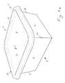
- FIG. 1 here is shown according to the invention an erected and formed packaging container 1 consisting of a bottom 2 and from the bottom folded-up side walls 3-6, which are position-oriented and fixed relative to each other in the erected condition by liquid tight side joints 7-10.
- the side joints 7-10 consist of a suitable joint material, preferably a solidifiable plastic material such as a thermoplastic.
- the packaging container 1 has a circumferential container opening 11, which has an opening edge 12 which also consists of the same material that connects the side walls 3-6, i.e. in the preferred embodiment, the thermoplastic.
- a heat sealable foil lid and re-closable snap-on lid be fixed.
- the erected packaging container (as in Fig 1 ) is mainly slightly conical rectangular with round opening but can also have other shapes such as rectangular-rectangular (as in Fig. 1b ), triangular, multi-angular, oval etc.
- the triangular embodiment would subsequently have the thermoplastic resin illustrated in Fig. 2 in the form of a strip formation 17 with only three legs.
- the opening edge 12 of thermoplastic resin is integrally formed with the side walls 3-6 liquid-tight uniting the side joints 7-10 of thermoplastic, which enclose the side wall edges 13-16 and their around extending opening edge 12, wherein the cohesive strip formation 17 of thermoplastic resin integrally extending from the opening edge 12 along the edge parts 13-16 of the side walls 3-6 and down to the bottom 2 of the container 1 while also creating a simultaneous fixation in position of all edge parts relative to each other.
- the sidewalls 3-6 consist in a first variant of a fiber-based packaging material 18 with at least one side coated with a heat sealable layer, wherein the thermoplastic mass joins and creates the side joints 7-10 of the packaging material and the integrally formed circumferential the opening edge 12.
- the cup is made of a packaging fiber based material without a sealable layer, which may be the case when the cup is to be used for dry products.
- a preferred method for the manufacture of a packaging container 1 according to the present invention can be achieved by a fiber based packaging material 18 in the form of a laminate, preferably having at least one side coated with a heat sealable layer, formed into a packaging container 1 in a mold 19, comprising two halves, of which either the one or the other is movable or fixed relative to each other and consisting of an outer part 20 and an inner part 21, for injection molding, in which a plastic melt of e.g. thermoplastic, liquid tight unites the side joints 7-10 of the packaging material 18 and create one with these undivided circumferential opening edge 12 of thermoplastic.
- the bottom 2 and the side walls 3-6 of the packaging container 1 are created by one and the same fiber based packaging blank.
- the packaging material 18 is shaped to a geometry defined by the three-dimensional shape of the mold, as in the depicted example with a fixed outer mold half or part 20 of the mold 19 and the movable inner part 21 of the mold 19 presses the packaging material 18 against the outer fixed part 20 of the mold 19, at the same time as the mold parts 20 and 21 thereby fix the packaging material 18 when finalizing the movement and lock the packaging material 18 in its final position lying against the outer part 20 of the mold 19, after which the plastic melt during injection fill first cavities 23, which are on the inside of the packaging material 18 and secondly those cavities 22, which are designed to accommodate the edges parts 13-16 of the side walls 3-6.
- the plastic melt fills these cavities 22, 23 without coming into contact with the outside of the packaging material 18 and connects the sidewalls 3-6 of the packaging material 18 to each other while forming the liquid tight joints 7-10 while the plastic melt also fills the cavities of the circumferential container opening 11 and by so then creating the liquid tight cup-shaped packaging container.
- Fig. 6 shows a mold 19 in a schematic, partial cross-sectional view for carrying out a method according to the invention to manufacture the packaging container 1.
- the mold 19 comprises two halves, an outer part 20 and an inner part 21.
- the outer part 20 is designed with flat surfaces for receiving the packaging material 18 which is placed against the same without overlap.
- the inner part 21 comprises a longitudinal recess 24 provided with edges, said edges 25,26 are intended to push the packing material 18 between themselves and the outer part 20 of the mold 19, and are extending just outside and on each side along the side joints 7-10, said edges 25,26 when pressing against the packaging material 18 during the injection molding forming the inner, first cavities 23 inside of the second cavities 22, which are designed to accommodate the side joints 7-10 for enabling a filling of the plastic mass both between the side wall edge parts 13-16 of the side walls 3-6 and in the inner first cavities 23 forming the recesses 24.
- Fig. 8 is schematically showing manufacturing of a packaging container 1 where the side walls 3-6 have been pressed against the outer part 20 of the mold 19 by incoming plastic melt 27 through flow channels 28-29, and so that the plastic melt from the injection point until it reaches the cavity 22 at the joining area, is distributed into two main flow channels 28-29 separated from each other and ending toward the edges 25,26 of the recess 24, so that the plastic melt thereby first fills the cavity 23 of the mold 19 closest to the edges 25,26 and only after that fills the cavity 22 at the joint area, by flowing of the plastic melt in upwards extending flow channels 30, so that the packaging material 18 is pressed against the outer part 20 of the mold 19 before the plastic melt 27 reaches the cavity 22 at the joint area, so that the forth coming wave front of the injected plastic melt presses the packaging material against the outer part 20 of the mold 19 before the plastic melt reaches the cavity 22 of the joint area, so that the plastic melt cannot enter the packaging material outside, which if it did would result in a container with appearance defects.
- a protruding part 31 working as a stacking device for stacking multiple cups into each other, lowers the pressure of the plastic melt when reaching this point.
Landscapes
- Engineering & Computer Science (AREA)
- Mechanical Engineering (AREA)
- Manufacturing & Machinery (AREA)
- Injection Moulding Of Plastics Or The Like (AREA)
- Moulds For Moulding Plastics Or The Like (AREA)
- Containers Having Bodies Formed In One Piece (AREA)
- Rigid Containers With Two Or More Constituent Elements (AREA)
Abstract
Description
- The invention relates to a method and a device for manufacturing a packaging container consisting of a cardboard bottom and from this bottom up-folded side walls which when erected are orientated and fixed relative to each other by means of liquid tight joints.
- The background to the present invention is that there is a market need to replace plastic cups for ice cream, crème fraiche, yoghurt and similar products, with cups that are made of more renewable raw materials and thus provide less contribution of greenhouse gases, i.e. more environmentally friendly cups and pots. Furthermore, it is common with lower environmental fees on packaging that consists of at least 50% cardboard, which also creates incentives for such cups. Today the market place does not offer such liquid tight cups, the ones which do exist are plastic cups placed into cardboard sleeves, which results in higher manufacturing cost, and also uses more plastic, or they perform poorly in modern automatic filling lines.
- The drawback of manufacturing a packaging container consisting of a cardboard bottom and from this bottom up-folded side walls, is that the ends of the side walls when exposed in an open cavity of an injection mold tool, in which the plastic mass forming the sealing joints is filled, is that the ends of the side walls can easily be pressed and pushed away by the plastic flow towards the inside or the outside of the cavity. It is sufficient with only a small difference in the cavities free flow channels resulting in displacement of the ends of the side walls, resulting in a packaging container with appearance defects. An unsymmetrical flooding of the plastic mass, resulting in such appearance defects, is due to that the plastic mass is injected at high pressure which pushes the side wall ends to one or the other side of the cavity in the injection mold-tool.
- An object with the present invention is to eliminate the drawbacks mentioned above by a new method and a device for carrying out said method. The characterizing features of the invention are stated in the subsequent patent claims.
- Thanks to the invention it has now been provided for a method and a device for manufacturing a packaging container of the kind mentioned above, which in an excellent way fulfills its purpose at the same time as the packaging container is both cheap and easy to manufacture. The packaging container, which by its conicity is stackable with equally shaped containers, consists of a cardboard based packaging material, preferably at least on one side coated with a heat sealable layer. The side joints are connectable in a liquid-tight manner by a melt consisting of preferably thermoplastic, while its top side comprises a circumferential opening edge along the container opening, which also is formed by e.g. thermoplastic. A solution to the above mentioned problem with the side wall ends moving inside of a cavity, is to arrange so that the packaging container have the side walls with its ends to rest directly rather than indirectly as previously, against the injection mold tool during the forming of the packaging. The plastic mass is filled only on the inside of the side walls and between the joints but not at the outside of the side walls. Thereby the packaging material is pressed towards the mold tool outer half by the force of the plastic mass and a stabilization of the entire packaging container position is obtained. The plastic mass creates a pressure against the packaging material so that the packaging material with great force is held in place towards the outer half of the injection mold tool. This in turn means that the plastic mass can completely fill the cavities between the side wall ends and on their inside, for creating the side wall joints, without any plastic mass entering to the outside of the side walls, so that no appearance defects occur.
- The invention is described closer below by the aid of some preferred embodiments with reference to the accompanying drawings, in which
- Fig. 1
- shows a perspective view of a packing container according to the invention,
- Fig. 1 b
- shows a perspective view of a rectangular execution of the packaging container illustrated in
Fig.1 , - Fig. 2
- shows separately in perspective a shell or strip formation of the thermoplastic mass contained in the
Fig. 1 illustrated packaging container, and which is intended to form the liquid-tight joints to hold together the same, - Fig. 3
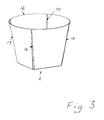
- shows separately in a perspective view actual fiber based packaging laminate in an erected and formed state, and which is included in that of
Fig. 1 illustrated packing container, - Fig. 4
- shows the packaging container illustrated in
Fig.1 in a view from below, - Fig. 5
- shows the packaging container illustrated in
Fig.1 in a view from above, - Fig. 6
- shows schematically a partial sectional view of an injection mold according to the invention with their halves in a position with the packaging material fixed between these,
- Fig. 7
- shows a schematic partial cross sectional view of an existing, prior known, injection mold design, and with which follows the disadvantages as described, and
- Fig. 8
- shows schematically one joint area of the packaging container, where incoming plastic melt flow divided from one incoming main flow into two flow channels.
- As in
Fig. 1 , here is shown according to the invention an erected and formedpackaging container 1 consisting of abottom 2 and from the bottom folded-up side walls 3-6, which are position-oriented and fixed relative to each other in the erected condition by liquid tight side joints 7-10. The side joints 7-10 consist of a suitable joint material, preferably a solidifiable plastic material such as a thermoplastic. Thepackaging container 1 has a circumferential container opening 11, which has anopening edge 12 which also consists of the same material that connects the side walls 3-6, i.e. in the preferred embodiment, the thermoplastic. Against theopening edge 12 may, when appropriate and not shown in the drawing here, a heat sealable foil lid and re-closable snap-on lid be fixed. - In the illustrated preferable embodiment of the invention the erected packaging container (as in
Fig 1 ) is mainly slightly conical rectangular with round opening but can also have other shapes such as rectangular-rectangular (as inFig. 1b ), triangular, multi-angular, oval etc. The triangular embodiment would subsequently have the thermoplastic resin illustrated inFig. 2 in the form of astrip formation 17 with only three legs. - As shown in the drawings, the
opening edge 12 of thermoplastic resin is integrally formed with the side walls 3-6 liquid-tight uniting the side joints 7-10 of thermoplastic, which enclose the side wall edges 13-16 and their around extendingopening edge 12, wherein thecohesive strip formation 17 of thermoplastic resin integrally extending from theopening edge 12 along the edge parts 13-16 of the side walls 3-6 and down to thebottom 2 of thecontainer 1 while also creating a simultaneous fixation in position of all edge parts relative to each other. - According to the invention the sidewalls 3-6 consist in a first variant of a fiber-based
packaging material 18 with at least one side coated with a heat sealable layer, wherein the thermoplastic mass joins and creates the side joints 7-10 of the packaging material and the integrally formed circumferential theopening edge 12. In another low cost variant of the invention, the cup is made of a packaging fiber based material without a sealable layer, which may be the case when the cup is to be used for dry products. - A preferred method for the manufacture of a
packaging container 1 according to the present invention can be achieved by a fiber basedpackaging material 18 in the form of a laminate, preferably having at least one side coated with a heat sealable layer, formed into apackaging container 1 in amold 19, comprising two halves, of which either the one or the other is movable or fixed relative to each other and consisting of anouter part 20 and aninner part 21, for injection molding, in which a plastic melt of e.g. thermoplastic, liquid tight unites the side joints 7-10 of thepackaging material 18 and create one with these undivided circumferentialopening edge 12 of thermoplastic. In the described and illustrated example thebottom 2 and the side walls 3-6 of thepackaging container 1 are created by one and the same fiber based packaging blank. - During forming, the
packaging material 18 is shaped to a geometry defined by the three-dimensional shape of the mold, as in the depicted example with a fixed outer mold half orpart 20 of themold 19 and the movableinner part 21 of themold 19 presses thepackaging material 18 against the outerfixed part 20 of themold 19, at the same time as themold parts packaging material 18 when finalizing the movement and lock thepackaging material 18 in its final position lying against theouter part 20 of themold 19, after which the plastic melt during injection fillfirst cavities 23, which are on the inside of thepackaging material 18 and secondly thosecavities 22, which are designed to accommodate the edges parts 13-16 of the side walls 3-6. The plastic melt fills thesecavities packaging material 18 and connects the sidewalls 3-6 of thepackaging material 18 to each other while forming the liquid tight joints 7-10 while the plastic melt also fills the cavities of the circumferential container opening 11 and by so then creating the liquid tight cup-shaped packaging container. -
Fig. 6 shows amold 19 in a schematic, partial cross-sectional view for carrying out a method according to the invention to manufacture thepackaging container 1. Themold 19 comprises two halves, anouter part 20 and aninner part 21. Theouter part 20 is designed with flat surfaces for receiving thepackaging material 18 which is placed against the same without overlap. Theinner part 21 comprises alongitudinal recess 24 provided with edges, saidedges packing material 18 between themselves and theouter part 20 of themold 19, and are extending just outside and on each side along the side joints 7-10, saidedges packaging material 18 during the injection molding forming the inner,first cavities 23 inside of thesecond cavities 22, which are designed to accommodate the side joints 7-10 for enabling a filling of the plastic mass both between the side wall edge parts 13-16 of the side walls 3-6 and in the innerfirst cavities 23 forming therecesses 24. -
Fig. 8 is schematically showing manufacturing of apackaging container 1 where the side walls 3-6 have been pressed against theouter part 20 of themold 19 by incomingplastic melt 27 through flow channels 28-29, and so that the plastic melt from the injection point until it reaches thecavity 22 at the joining area, is distributed into two main flow channels 28-29 separated from each other and ending toward theedges recess 24, so that the plastic melt thereby first fills thecavity 23 of themold 19 closest to theedges cavity 22 at the joint area, by flowing of the plastic melt in upwards extendingflow channels 30, so that thepackaging material 18 is pressed against theouter part 20 of themold 19 before theplastic melt 27 reaches thecavity 22 at the joint area, so that the forth coming wave front of the injected plastic melt presses the packaging material against theouter part 20 of themold 19 before the plastic melt reaches thecavity 22 of the joint area, so that the plastic melt cannot enter the packaging material outside, which if it did would result in a container with appearance defects. Furthermore a protrudingpart 31, working as a stacking device for stacking multiple cups into each other, lowers the pressure of the plastic melt when reaching this point. The protrudingpart 31, located just adjacent to the packaging material side ends, creates a controlled deceleration of the rushing plastic flow, by the relatively large volume of theprotruding part 31, which when filled with plastic melt lowers the pressure and thus creates a delay in the filling of the cavity which facilitates for the plastic flow to press the packaging material against theouter part 20 of themold 19 while first thereafter is also filling the strip-formed legs and side joints 7-10 upwards.
Claims (3)
- A method for manufacturing a packaging container (1) consisting of a bottom (2) and from this bottom up-folded side walls (3-6), which are fixable relative to each other in an erected state by liquid-tight side joints (7-10), wherein a fiber based packaging material (18) preferably having at least one side coated with a heat sealable layer is formed into said packaging container (1) in a mold (19) having two relative to each other moveable halves constituting an outer part (20) and an inner part (21) for injection molding in which a plastic melt of preferably thermoplastic, liquid-tight, joins the side walls (3-6) of the packaging material (18) with their edge parts (13-16) by said side joints (7-10) and creates a circumferential opening edge (12) of thermoplastic formed integrally with said side joints (7-10), wherein during the forming, the packaging material (18) assumes the geometric shape defined by the three-dimensional shape of the outer mold part (20) after which the mold inner part (21) presses the packaging material (18) towards the mold outer part (20) while the mold halves thereby fix the packaging material (18) and locks the same in its final position against the mold outer part (20), characterized in that said plastic melt during the injection molding only fills first cavities (23), on the inside of the packing material and second cavities (22) designed to accommodate the edge parts (13-16) of the side walls (13-16), where the plastic melt during injection fills these cavities (22,23) without coming in contact with the outside of the packaging material (18) and thus connects the sidewalls (3-6) of the packaging material with each other to form the liquid tight side joints (7-10), while the plastic melt also fill the cavity of the circumferential opening edge (12) for the creation of a liquid tight cup shaped packaging container.
- A method according to claim 1, characterized in that during injection molding of the packaging container, the side walls (3-6) of the packaging material are pressed against the outer part (20) of the mold (19) by the incoming plastic melt (27) which is controlled so that the plastic melt from the injection point until it reaches the cavity (23) is distributed into two main flow channels (28,29) separated from each other, and further up into the side joints (7-10) or in the so-called leg-formed cavities (23) and there branches into a plurality above each other in the cavities (23) extending channels (30).
- A device for carrying out a method according to claim 1 or 2, in which the molding outer part (20) of the mold (19) is designed with flat surfaces for receiving the packaging material (18) which is pressed directly against the same without overlapping, characterized in that the inner part (21) of the mold (19) having edge provided longitudinal recesses (24), the edges (25,26) of which are intended to press the packaging material (18) between itself and the outer part (20) of the forming mold (19) and are extending just outside and on each side along the side joins (7-10), said edges (25,26) during their contact against the packaging material (18) is pressing against said packaging material (18) during the injection molding and forming first cavities (23) between themselves within or inside second cavities (22), which are formed and intended to receive the side joints (7-10) of the packaging material (18) for enabling filling of the plastic mass both in between the edge parts (13-16) of the side walls (3-6) and in the first cavities (23), forming the recesses (24) located between the edges (25,26).
Priority Applications (4)
| Application Number | Priority Date | Filing Date | Title |
|---|---|---|---|
| EP14003932.2A EP3023218B1 (en) | 2014-11-21 | 2014-11-21 | A method for manufacturing of a package container |
| HUE14003932A HUE038254T2 (en) | 2014-11-21 | 2014-11-21 | A method for manufacturing of a package container |
| DK14003932.2T DK3023218T3 (en) | 2014-11-21 | 2014-11-21 | Process for making a packaging container |
| PL14003932T PL3023218T3 (en) | 2014-11-21 | 2014-11-21 | A method for manufacturing of a package container |
Applications Claiming Priority (1)
| Application Number | Priority Date | Filing Date | Title |
|---|---|---|---|
| EP14003932.2A EP3023218B1 (en) | 2014-11-21 | 2014-11-21 | A method for manufacturing of a package container |
Publications (2)
| Publication Number | Publication Date |
|---|---|
| EP3023218A1 true EP3023218A1 (en) | 2016-05-25 |
| EP3023218B1 EP3023218B1 (en) | 2018-03-28 |
Family
ID=52133759
Family Applications (1)
| Application Number | Title | Priority Date | Filing Date |
|---|---|---|---|
| EP14003932.2A Active EP3023218B1 (en) | 2014-11-21 | 2014-11-21 | A method for manufacturing of a package container |
Country Status (4)
| Country | Link |
|---|---|
| EP (1) | EP3023218B1 (en) |
| DK (1) | DK3023218T3 (en) |
| HU (1) | HUE038254T2 (en) |
| PL (1) | PL3023218T3 (en) |
Cited By (1)
| Publication number | Priority date | Publication date | Assignee | Title |
|---|---|---|---|---|
| CN114630743A (en) * | 2019-11-05 | 2022-06-14 | 弗伯哈(德国)有限公司 | Apparatus and method for manufacturing composite articles with injection molding features |
Citations (9)
| Publication number | Priority date | Publication date | Assignee | Title |
|---|---|---|---|---|
| GB1348370A (en) * | 1970-05-13 | 1974-03-13 | Airfix Ind Ltd | Method of making containers |
| GB1502266A (en) * | 1974-05-28 | 1978-03-01 | Airfix Ind Ltd | Composite containers |
| GB1504527A (en) * | 1974-05-31 | 1978-03-22 | Airfix Ind Ltd | Containers |
| GB1570393A (en) * | 1975-12-29 | 1980-07-02 | Airfix Ind Ltd | Production of composite articles |
| JPH03197109A (en) * | 1989-12-27 | 1991-08-28 | Dainippon Printing Co Ltd | Manufacture of pillared container |
| JP2002225828A (en) * | 2001-01-26 | 2002-08-14 | Yoshino Kogyosho Co Ltd | Sticking body such as label and method of molding polygon cylindrical vessel for inmold-forming the same |
| WO2009086501A2 (en) * | 2007-12-28 | 2009-07-09 | Graphic Packaging International, Inc. | Injection-molded composite construct and tool for forming construct |
| US20110065556A1 (en) * | 2002-03-15 | 2011-03-17 | Graphic Packaging International, Inc. | Container Having A Rim Or Other Feature Encapsulated By Or Formed From Injection-Molded Material |
| WO2012022672A1 (en) * | 2010-08-20 | 2012-02-23 | Nestec S.A. | An in-mould labelled container |
-
2014
- 2014-11-21 EP EP14003932.2A patent/EP3023218B1/en active Active
- 2014-11-21 DK DK14003932.2T patent/DK3023218T3/en active
- 2014-11-21 PL PL14003932T patent/PL3023218T3/en unknown
- 2014-11-21 HU HUE14003932A patent/HUE038254T2/en unknown
Patent Citations (9)
| Publication number | Priority date | Publication date | Assignee | Title |
|---|---|---|---|---|
| GB1348370A (en) * | 1970-05-13 | 1974-03-13 | Airfix Ind Ltd | Method of making containers |
| GB1502266A (en) * | 1974-05-28 | 1978-03-01 | Airfix Ind Ltd | Composite containers |
| GB1504527A (en) * | 1974-05-31 | 1978-03-22 | Airfix Ind Ltd | Containers |
| GB1570393A (en) * | 1975-12-29 | 1980-07-02 | Airfix Ind Ltd | Production of composite articles |
| JPH03197109A (en) * | 1989-12-27 | 1991-08-28 | Dainippon Printing Co Ltd | Manufacture of pillared container |
| JP2002225828A (en) * | 2001-01-26 | 2002-08-14 | Yoshino Kogyosho Co Ltd | Sticking body such as label and method of molding polygon cylindrical vessel for inmold-forming the same |
| US20110065556A1 (en) * | 2002-03-15 | 2011-03-17 | Graphic Packaging International, Inc. | Container Having A Rim Or Other Feature Encapsulated By Or Formed From Injection-Molded Material |
| WO2009086501A2 (en) * | 2007-12-28 | 2009-07-09 | Graphic Packaging International, Inc. | Injection-molded composite construct and tool for forming construct |
| WO2012022672A1 (en) * | 2010-08-20 | 2012-02-23 | Nestec S.A. | An in-mould labelled container |
Cited By (1)
| Publication number | Priority date | Publication date | Assignee | Title |
|---|---|---|---|---|
| CN114630743A (en) * | 2019-11-05 | 2022-06-14 | 弗伯哈(德国)有限公司 | Apparatus and method for manufacturing composite articles with injection molding features |
Also Published As
| Publication number | Publication date |
|---|---|
| PL3023218T3 (en) | 2018-09-28 |
| HUE038254T2 (en) | 2018-10-29 |
| EP3023218B1 (en) | 2018-03-28 |
| DK3023218T3 (en) | 2018-07-09 |
Similar Documents
| Publication | Publication Date | Title |
|---|---|---|
| JP6556730B2 (en) | Partial capsules for preparing extracted products | |
| RU2563761C2 (en) | Package, method of its fabrication and forming tool | |
| RU2671902C2 (en) | Packaging material blank, package with such device and a method for manufacturing an opening device | |
| ES2427838T3 (en) | A procedure to form a container and a container | |
| JP5072849B2 (en) | Board / tray manufacturing method, blank for the tray, and tray obtained by the method | |
| JP2017508492A5 (en) | ||
| JP2017530876A (en) | Molding apparatus and method for manufacturing unsealing apparatus | |
| US12076958B2 (en) | Manufacturing process for producing hermetic single-use food containers such as coffee pods, including a creasing step | |
| KR20160105422A (en) | An apparatus and a method for forming opening devices on a sheet packaging material for packaging pourable food products | |
| EP3194139A1 (en) | Molding apparatus and method for manufacturing an opening device | |
| KR20150018510A (en) | Capsule | |
| MX2013001532A (en) | Method for forming a package, a package and a package blank. | |
| US3406873A (en) | Collapsible container | |
| EP3023218B1 (en) | A method for manufacturing of a package container | |
| WO2017072007A1 (en) | A liquid food package, a method for producing the same and a machine | |
| US20160167268A1 (en) | Method and injection mold for producing an insert part having a plastic collar | |
| WO2018122743A1 (en) | Container for pourable food products | |
| EP1974898B1 (en) | Method for forming three-dimensional containers of extensible paper material. | |
| JP2012126423A (en) | Blank for tray-type container, and tray-type container | |
| JP2017036086A (en) | Food storage container made of pulp material | |
| WO2016037818A1 (en) | Molding apparatus and method for manufacturing an opening device | |
| ITVE960001A1 (en) | PAPER MATERIAL TO MAKE THREE-DIMENSIONAL SOFT PACKAGES FOR SOLID, LIQUID, POSSIBLY SOLIDIFIABLE STATE PRODUCTS | |
| CN212862233U (en) | Single-side inner-side rubber-coated paper-plastic combined formed packaging box | |
| CN104352131A (en) | In-mold labeled injection-molded thin film plastic cup | |
| SE541488C2 (en) | Method and device for manufacturing a packaging container |
Legal Events
| Date | Code | Title | Description |
|---|---|---|---|
| AK | Designated contracting states |
Kind code of ref document: A1 Designated state(s): AL AT BE BG CH CY CZ DE DK EE ES FI FR GB GR HR HU IE IS IT LI LT LU LV MC MK MT NL NO PL PT RO RS SE SI SK SM TR |
|
| AX | Request for extension of the european patent |
Extension state: BA ME |
|
| PUAI | Public reference made under article 153(3) epc to a published international application that has entered the european phase |
Free format text: ORIGINAL CODE: 0009012 |
|
| 17P | Request for examination filed |
Effective date: 20161123 |
|
| RBV | Designated contracting states (corrected) |
Designated state(s): AL AT BE BG CH CY CZ DE DK EE ES FI FR GB GR HR HU IE IS IT LI LT LU LV MC MK MT NL NO PL PT RO RS SE SI SK SM TR |
|
| 17Q | First examination report despatched |
Effective date: 20170320 |
|
| GRAP | Despatch of communication of intention to grant a patent |
Free format text: ORIGINAL CODE: EPIDOSNIGR1 |
|
| INTG | Intention to grant announced |
Effective date: 20171017 |
|
| GRAS | Grant fee paid |
Free format text: ORIGINAL CODE: EPIDOSNIGR3 |
|
| GRAA | (expected) grant |
Free format text: ORIGINAL CODE: 0009210 |
|
| AK | Designated contracting states |
Kind code of ref document: B1 Designated state(s): AL AT BE BG CH CY CZ DE DK EE ES FI FR GB GR HR HU IE IS IT LI LT LU LV MC MK MT NL NO PL PT RO RS SE SI SK SM TR |
|
| REG | Reference to a national code |
Ref country code: GB Ref legal event code: FG4D |
|
| REG | Reference to a national code |
Ref country code: CH Ref legal event code: EP |
|
| REG | Reference to a national code |
Ref country code: AT Ref legal event code: REF Ref document number: 982995 Country of ref document: AT Kind code of ref document: T Effective date: 20180415 |
|
| REG | Reference to a national code |
Ref country code: IE Ref legal event code: FG4D |
|
| REG | Reference to a national code |
Ref country code: DE Ref legal event code: R096 Ref document number: 602014022867 Country of ref document: DE |
|
| REG | Reference to a national code |
Ref country code: DK Ref legal event code: T3 Effective date: 20180706 |
|
| REG | Reference to a national code |
Ref country code: SE Ref legal event code: TRGR |
|
| REG | Reference to a national code |
Ref country code: NL Ref legal event code: FP |
|
| PG25 | Lapsed in a contracting state [announced via postgrant information from national office to epo] |
Ref country code: HR Free format text: LAPSE BECAUSE OF FAILURE TO SUBMIT A TRANSLATION OF THE DESCRIPTION OR TO PAY THE FEE WITHIN THE PRESCRIBED TIME-LIMIT Effective date: 20180328 Ref country code: LT Free format text: LAPSE BECAUSE OF FAILURE TO SUBMIT A TRANSLATION OF THE DESCRIPTION OR TO PAY THE FEE WITHIN THE PRESCRIBED TIME-LIMIT Effective date: 20180328 |
|
| REG | Reference to a national code |
Ref country code: LT Ref legal event code: MG4D |
|
| REG | Reference to a national code |
Ref country code: EE Ref legal event code: FG4A Ref document number: E015620 Country of ref document: EE Effective date: 20180628 |
|
| REG | Reference to a national code |
Ref country code: NO Ref legal event code: T2 Effective date: 20180328 |
|
| PG25 | Lapsed in a contracting state [announced via postgrant information from national office to epo] |
Ref country code: LV Free format text: LAPSE BECAUSE OF FAILURE TO SUBMIT A TRANSLATION OF THE DESCRIPTION OR TO PAY THE FEE WITHIN THE PRESCRIBED TIME-LIMIT Effective date: 20180328 Ref country code: RS Free format text: LAPSE BECAUSE OF FAILURE TO SUBMIT A TRANSLATION OF THE DESCRIPTION OR TO PAY THE FEE WITHIN THE PRESCRIBED TIME-LIMIT Effective date: 20180328 Ref country code: GR Free format text: LAPSE BECAUSE OF FAILURE TO SUBMIT A TRANSLATION OF THE DESCRIPTION OR TO PAY THE FEE WITHIN THE PRESCRIBED TIME-LIMIT Effective date: 20180629 Ref country code: BG Free format text: LAPSE BECAUSE OF FAILURE TO SUBMIT A TRANSLATION OF THE DESCRIPTION OR TO PAY THE FEE WITHIN THE PRESCRIBED TIME-LIMIT Effective date: 20180628 |
|
| REG | Reference to a national code |
Ref country code: HU Ref legal event code: AG4A Ref document number: E038254 Country of ref document: HU |
|
| PG25 | Lapsed in a contracting state [announced via postgrant information from national office to epo] |
Ref country code: AL Free format text: LAPSE BECAUSE OF FAILURE TO SUBMIT A TRANSLATION OF THE DESCRIPTION OR TO PAY THE FEE WITHIN THE PRESCRIBED TIME-LIMIT Effective date: 20180328 Ref country code: ES Free format text: LAPSE BECAUSE OF FAILURE TO SUBMIT A TRANSLATION OF THE DESCRIPTION OR TO PAY THE FEE WITHIN THE PRESCRIBED TIME-LIMIT Effective date: 20180328 Ref country code: IT Free format text: LAPSE BECAUSE OF FAILURE TO SUBMIT A TRANSLATION OF THE DESCRIPTION OR TO PAY THE FEE WITHIN THE PRESCRIBED TIME-LIMIT Effective date: 20180328 Ref country code: RO Free format text: LAPSE BECAUSE OF FAILURE TO SUBMIT A TRANSLATION OF THE DESCRIPTION OR TO PAY THE FEE WITHIN THE PRESCRIBED TIME-LIMIT Effective date: 20180328 |
|
| PG25 | Lapsed in a contracting state [announced via postgrant information from national office to epo] |
Ref country code: SK Free format text: LAPSE BECAUSE OF FAILURE TO SUBMIT A TRANSLATION OF THE DESCRIPTION OR TO PAY THE FEE WITHIN THE PRESCRIBED TIME-LIMIT Effective date: 20180328 Ref country code: SM Free format text: LAPSE BECAUSE OF FAILURE TO SUBMIT A TRANSLATION OF THE DESCRIPTION OR TO PAY THE FEE WITHIN THE PRESCRIBED TIME-LIMIT Effective date: 20180328 Ref country code: CZ Free format text: LAPSE BECAUSE OF FAILURE TO SUBMIT A TRANSLATION OF THE DESCRIPTION OR TO PAY THE FEE WITHIN THE PRESCRIBED TIME-LIMIT Effective date: 20180328 |
|
| PG25 | Lapsed in a contracting state [announced via postgrant information from national office to epo] |
Ref country code: PT Free format text: LAPSE BECAUSE OF FAILURE TO SUBMIT A TRANSLATION OF THE DESCRIPTION OR TO PAY THE FEE WITHIN THE PRESCRIBED TIME-LIMIT Effective date: 20180730 |
|
| REG | Reference to a national code |
Ref country code: DE Ref legal event code: R097 Ref document number: 602014022867 Country of ref document: DE |
|
| PLBE | No opposition filed within time limit |
Free format text: ORIGINAL CODE: 0009261 |
|
| STAA | Information on the status of an ep patent application or granted ep patent |
Free format text: STATUS: NO OPPOSITION FILED WITHIN TIME LIMIT |
|
| 26N | No opposition filed |
Effective date: 20190103 |
|
| PG25 | Lapsed in a contracting state [announced via postgrant information from national office to epo] |
Ref country code: SI Free format text: LAPSE BECAUSE OF FAILURE TO SUBMIT A TRANSLATION OF THE DESCRIPTION OR TO PAY THE FEE WITHIN THE PRESCRIBED TIME-LIMIT Effective date: 20180328 |
|
| PG25 | Lapsed in a contracting state [announced via postgrant information from national office to epo] |
Ref country code: LU Free format text: LAPSE BECAUSE OF NON-PAYMENT OF DUE FEES Effective date: 20181121 Ref country code: MC Free format text: LAPSE BECAUSE OF FAILURE TO SUBMIT A TRANSLATION OF THE DESCRIPTION OR TO PAY THE FEE WITHIN THE PRESCRIBED TIME-LIMIT Effective date: 20180328 |
|
| REG | Reference to a national code |
Ref country code: BE Ref legal event code: MM Effective date: 20181130 |
|
| REG | Reference to a national code |
Ref country code: IE Ref legal event code: MM4A |
|
| PG25 | Lapsed in a contracting state [announced via postgrant information from national office to epo] |
Ref country code: IE Free format text: LAPSE BECAUSE OF NON-PAYMENT OF DUE FEES Effective date: 20181121 |
|
| PG25 | Lapsed in a contracting state [announced via postgrant information from national office to epo] |
Ref country code: BE Free format text: LAPSE BECAUSE OF NON-PAYMENT OF DUE FEES Effective date: 20181130 |
|
| PG25 | Lapsed in a contracting state [announced via postgrant information from national office to epo] |
Ref country code: MT Free format text: LAPSE BECAUSE OF NON-PAYMENT OF DUE FEES Effective date: 20181121 |
|
| PG25 | Lapsed in a contracting state [announced via postgrant information from national office to epo] |
Ref country code: TR Free format text: LAPSE BECAUSE OF FAILURE TO SUBMIT A TRANSLATION OF THE DESCRIPTION OR TO PAY THE FEE WITHIN THE PRESCRIBED TIME-LIMIT Effective date: 20180328 |
|
| PG25 | Lapsed in a contracting state [announced via postgrant information from national office to epo] |
Ref country code: CY Free format text: LAPSE BECAUSE OF FAILURE TO SUBMIT A TRANSLATION OF THE DESCRIPTION OR TO PAY THE FEE WITHIN THE PRESCRIBED TIME-LIMIT Effective date: 20180328 Ref country code: MK Free format text: LAPSE BECAUSE OF NON-PAYMENT OF DUE FEES Effective date: 20180328 |
|
| PG25 | Lapsed in a contracting state [announced via postgrant information from national office to epo] |
Ref country code: IS Free format text: LAPSE BECAUSE OF FAILURE TO SUBMIT A TRANSLATION OF THE DESCRIPTION OR TO PAY THE FEE WITHIN THE PRESCRIBED TIME-LIMIT Effective date: 20180728 |
|
| REG | Reference to a national code |
Ref country code: AT Ref legal event code: UEP Ref document number: 982995 Country of ref document: AT Kind code of ref document: T Effective date: 20180328 |
|
| P01 | Opt-out of the competence of the unified patent court (upc) registered |
Effective date: 20230620 |
|
| REG | Reference to a national code |
Ref country code: CH Ref legal event code: U11 Free format text: ST27 STATUS EVENT CODE: U-0-0-U10-U11 (AS PROVIDED BY THE NATIONAL OFFICE) Effective date: 20251201 |
|
| PGFP | Annual fee paid to national office [announced via postgrant information from national office to epo] |
Ref country code: HU Payment date: 20251031 Year of fee payment: 12 |
|
| PGFP | Annual fee paid to national office [announced via postgrant information from national office to epo] |
Ref country code: NL Payment date: 20251121 Year of fee payment: 12 |
|
| PGFP | Annual fee paid to national office [announced via postgrant information from national office to epo] |
Ref country code: DE Payment date: 20251118 Year of fee payment: 12 |
|
| PGFP | Annual fee paid to national office [announced via postgrant information from national office to epo] |
Ref country code: GB Payment date: 20251117 Year of fee payment: 12 |
|
| PGFP | Annual fee paid to national office [announced via postgrant information from national office to epo] |
Ref country code: NO Payment date: 20251120 Year of fee payment: 12 |
|
| PGFP | Annual fee paid to national office [announced via postgrant information from national office to epo] |
Ref country code: AT Payment date: 20251118 Year of fee payment: 12 |
|
| PGFP | Annual fee paid to national office [announced via postgrant information from national office to epo] |
Ref country code: FI Payment date: 20251118 Year of fee payment: 12 Ref country code: DK Payment date: 20251120 Year of fee payment: 12 |
|
| PGFP | Annual fee paid to national office [announced via postgrant information from national office to epo] |
Ref country code: FR Payment date: 20251117 Year of fee payment: 12 |
|
| PGFP | Annual fee paid to national office [announced via postgrant information from national office to epo] |
Ref country code: SE Payment date: 20251121 Year of fee payment: 12 Ref country code: CH Payment date: 20251201 Year of fee payment: 12 |
|
| PGFP | Annual fee paid to national office [announced via postgrant information from national office to epo] |
Ref country code: PL Payment date: 20251021 Year of fee payment: 12 |
|
| PGFP | Annual fee paid to national office [announced via postgrant information from national office to epo] |
Ref country code: EE Payment date: 20251128 Year of fee payment: 12 |