EP3023215A1 - Optical fiber recoating device - Google Patents
Optical fiber recoating device Download PDFInfo
- Publication number
- EP3023215A1 EP3023215A1 EP14896959.5A EP14896959A EP3023215A1 EP 3023215 A1 EP3023215 A1 EP 3023215A1 EP 14896959 A EP14896959 A EP 14896959A EP 3023215 A1 EP3023215 A1 EP 3023215A1
- Authority
- EP
- European Patent Office
- Prior art keywords
- optical fiber
- glass
- lateral pressing
- glass member
- members
- Prior art date
- Legal status (The legal status is an assumption and is not a legal conclusion. Google has not performed a legal analysis and makes no representation as to the accuracy of the status listed.)
- Granted
Links
Images


Classifications
-
- B—PERFORMING OPERATIONS; TRANSPORTING
- B29—WORKING OF PLASTICS; WORKING OF SUBSTANCES IN A PLASTIC STATE IN GENERAL
- B29C—SHAPING OR JOINING OF PLASTICS; SHAPING OF MATERIAL IN A PLASTIC STATE, NOT OTHERWISE PROVIDED FOR; AFTER-TREATMENT OF THE SHAPED PRODUCTS, e.g. REPAIRING
- B29C45/00—Injection moulding, i.e. forcing the required volume of moulding material through a nozzle into a closed mould; Apparatus therefor
- B29C45/17—Component parts, details or accessories; Auxiliary operations
- B29C45/1742—Mounting of moulds; Mould supports
-
- G—PHYSICS
- G02—OPTICS
- G02B—OPTICAL ELEMENTS, SYSTEMS OR APPARATUS
- G02B6/00—Light guides; Structural details of arrangements comprising light guides and other optical elements, e.g. couplings
- G02B6/24—Coupling light guides
- G02B6/255—Splicing of light guides, e.g. by fusion or bonding
- G02B6/2558—Reinforcement of splice joint
-
- B—PERFORMING OPERATIONS; TRANSPORTING
- B29—WORKING OF PLASTICS; WORKING OF SUBSTANCES IN A PLASTIC STATE IN GENERAL
- B29C—SHAPING OR JOINING OF PLASTICS; SHAPING OF MATERIAL IN A PLASTIC STATE, NOT OTHERWISE PROVIDED FOR; AFTER-TREATMENT OF THE SHAPED PRODUCTS, e.g. REPAIRING
- B29C33/00—Moulds or cores; Details thereof or accessories therefor
- B29C33/38—Moulds or cores; Details thereof or accessories therefor characterised by the material or the manufacturing process
-
- B—PERFORMING OPERATIONS; TRANSPORTING
- B29—WORKING OF PLASTICS; WORKING OF SUBSTANCES IN A PLASTIC STATE IN GENERAL
- B29C—SHAPING OR JOINING OF PLASTICS; SHAPING OF MATERIAL IN A PLASTIC STATE, NOT OTHERWISE PROVIDED FOR; AFTER-TREATMENT OF THE SHAPED PRODUCTS, e.g. REPAIRING
- B29C35/00—Heating, cooling or curing, e.g. crosslinking or vulcanising; Apparatus therefor
- B29C35/02—Heating or curing, e.g. crosslinking or vulcanizing during moulding, e.g. in a mould
- B29C35/08—Heating or curing, e.g. crosslinking or vulcanizing during moulding, e.g. in a mould by wave energy or particle radiation
- B29C35/0805—Heating or curing, e.g. crosslinking or vulcanizing during moulding, e.g. in a mould by wave energy or particle radiation using electromagnetic radiation
-
- B—PERFORMING OPERATIONS; TRANSPORTING
- B29—WORKING OF PLASTICS; WORKING OF SUBSTANCES IN A PLASTIC STATE IN GENERAL
- B29C—SHAPING OR JOINING OF PLASTICS; SHAPING OF MATERIAL IN A PLASTIC STATE, NOT OTHERWISE PROVIDED FOR; AFTER-TREATMENT OF THE SHAPED PRODUCTS, e.g. REPAIRING
- B29C45/00—Injection moulding, i.e. forcing the required volume of moulding material through a nozzle into a closed mould; Apparatus therefor
- B29C45/14—Injection moulding, i.e. forcing the required volume of moulding material through a nozzle into a closed mould; Apparatus therefor incorporating preformed parts or layers, e.g. injection moulding around inserts or for coating articles
- B29C45/14065—Positioning or centering articles in the mould
-
- B—PERFORMING OPERATIONS; TRANSPORTING
- B29—WORKING OF PLASTICS; WORKING OF SUBSTANCES IN A PLASTIC STATE IN GENERAL
- B29C—SHAPING OR JOINING OF PLASTICS; SHAPING OF MATERIAL IN A PLASTIC STATE, NOT OTHERWISE PROVIDED FOR; AFTER-TREATMENT OF THE SHAPED PRODUCTS, e.g. REPAIRING
- B29C45/00—Injection moulding, i.e. forcing the required volume of moulding material through a nozzle into a closed mould; Apparatus therefor
- B29C45/14—Injection moulding, i.e. forcing the required volume of moulding material through a nozzle into a closed mould; Apparatus therefor incorporating preformed parts or layers, e.g. injection moulding around inserts or for coating articles
- B29C45/14549—Coating rod-like, wire-like or belt-like articles
-
- B—PERFORMING OPERATIONS; TRANSPORTING
- B29—WORKING OF PLASTICS; WORKING OF SUBSTANCES IN A PLASTIC STATE IN GENERAL
- B29C—SHAPING OR JOINING OF PLASTICS; SHAPING OF MATERIAL IN A PLASTIC STATE, NOT OTHERWISE PROVIDED FOR; AFTER-TREATMENT OF THE SHAPED PRODUCTS, e.g. REPAIRING
- B29C45/00—Injection moulding, i.e. forcing the required volume of moulding material through a nozzle into a closed mould; Apparatus therefor
- B29C45/17—Component parts, details or accessories; Auxiliary operations
- B29C45/1742—Mounting of moulds; Mould supports
- B29C45/1744—Mould support platens
-
- B—PERFORMING OPERATIONS; TRANSPORTING
- B29—WORKING OF PLASTICS; WORKING OF SUBSTANCES IN A PLASTIC STATE IN GENERAL
- B29C—SHAPING OR JOINING OF PLASTICS; SHAPING OF MATERIAL IN A PLASTIC STATE, NOT OTHERWISE PROVIDED FOR; AFTER-TREATMENT OF THE SHAPED PRODUCTS, e.g. REPAIRING
- B29C45/00—Injection moulding, i.e. forcing the required volume of moulding material through a nozzle into a closed mould; Apparatus therefor
- B29C45/17—Component parts, details or accessories; Auxiliary operations
- B29C45/26—Moulds
-
- B—PERFORMING OPERATIONS; TRANSPORTING
- B29—WORKING OF PLASTICS; WORKING OF SUBSTANCES IN A PLASTIC STATE IN GENERAL
- B29D—PRODUCING PARTICULAR ARTICLES FROM PLASTICS OR FROM SUBSTANCES IN A PLASTIC STATE
- B29D11/00—Producing optical elements, e.g. lenses or prisms
- B29D11/00865—Applying coatings; tinting; colouring
- B29D11/00875—Applying coatings; tinting; colouring on light guides
-
- C—CHEMISTRY; METALLURGY
- C03—GLASS; MINERAL OR SLAG WOOL
- C03C—CHEMICAL COMPOSITION OF GLASSES, GLAZES OR VITREOUS ENAMELS; SURFACE TREATMENT OF GLASS; SURFACE TREATMENT OF FIBRES OR FILAMENTS MADE FROM GLASS, MINERALS OR SLAGS; JOINING GLASS TO GLASS OR OTHER MATERIALS
- C03C25/00—Surface treatment of fibres or filaments made from glass, minerals or slags
- C03C25/10—Coating
- C03C25/104—Coating to obtain optical fibres
- C03C25/106—Single coatings
-
- C—CHEMISTRY; METALLURGY
- C03—GLASS; MINERAL OR SLAG WOOL
- C03C—CHEMICAL COMPOSITION OF GLASSES, GLAZES OR VITREOUS ENAMELS; SURFACE TREATMENT OF GLASS; SURFACE TREATMENT OF FIBRES OR FILAMENTS MADE FROM GLASS, MINERALS OR SLAGS; JOINING GLASS TO GLASS OR OTHER MATERIALS
- C03C3/00—Glass compositions
- C03C3/04—Glass compositions containing silica
- C03C3/06—Glass compositions containing silica with more than 90% silica by weight, e.g. quartz
-
- B—PERFORMING OPERATIONS; TRANSPORTING
- B29—WORKING OF PLASTICS; WORKING OF SUBSTANCES IN A PLASTIC STATE IN GENERAL
- B29C—SHAPING OR JOINING OF PLASTICS; SHAPING OF MATERIAL IN A PLASTIC STATE, NOT OTHERWISE PROVIDED FOR; AFTER-TREATMENT OF THE SHAPED PRODUCTS, e.g. REPAIRING
- B29C35/00—Heating, cooling or curing, e.g. crosslinking or vulcanising; Apparatus therefor
- B29C35/02—Heating or curing, e.g. crosslinking or vulcanizing during moulding, e.g. in a mould
- B29C35/08—Heating or curing, e.g. crosslinking or vulcanizing during moulding, e.g. in a mould by wave energy or particle radiation
- B29C35/0805—Heating or curing, e.g. crosslinking or vulcanizing during moulding, e.g. in a mould by wave energy or particle radiation using electromagnetic radiation
- B29C2035/0827—Heating or curing, e.g. crosslinking or vulcanizing during moulding, e.g. in a mould by wave energy or particle radiation using electromagnetic radiation using UV radiation
-
- B—PERFORMING OPERATIONS; TRANSPORTING
- B29—WORKING OF PLASTICS; WORKING OF SUBSTANCES IN A PLASTIC STATE IN GENERAL
- B29C—SHAPING OR JOINING OF PLASTICS; SHAPING OF MATERIAL IN A PLASTIC STATE, NOT OTHERWISE PROVIDED FOR; AFTER-TREATMENT OF THE SHAPED PRODUCTS, e.g. REPAIRING
- B29C45/00—Injection moulding, i.e. forcing the required volume of moulding material through a nozzle into a closed mould; Apparatus therefor
- B29C45/17—Component parts, details or accessories; Auxiliary operations
- B29C45/26—Moulds
- B29C45/261—Moulds having tubular mould cavities
-
- B—PERFORMING OPERATIONS; TRANSPORTING
- B29—WORKING OF PLASTICS; WORKING OF SUBSTANCES IN A PLASTIC STATE IN GENERAL
- B29K—INDEXING SCHEME ASSOCIATED WITH SUBCLASSES B29B, B29C OR B29D, RELATING TO MOULDING MATERIALS OR TO MATERIALS FOR MOULDS, REINFORCEMENTS, FILLERS OR PREFORMED PARTS, e.g. INSERTS
- B29K2105/00—Condition, form or state of moulded material or of the material to be shaped
- B29K2105/0058—Liquid or visquous
-
- B—PERFORMING OPERATIONS; TRANSPORTING
- B29—WORKING OF PLASTICS; WORKING OF SUBSTANCES IN A PLASTIC STATE IN GENERAL
- B29K—INDEXING SCHEME ASSOCIATED WITH SUBCLASSES B29B, B29C OR B29D, RELATING TO MOULDING MATERIALS OR TO MATERIALS FOR MOULDS, REINFORCEMENTS, FILLERS OR PREFORMED PARTS, e.g. INSERTS
- B29K2909/00—Use of inorganic materials not provided for in groups B29K2803/00 - B29K2807/00, as mould material
- B29K2909/08—Glass
-
- B—PERFORMING OPERATIONS; TRANSPORTING
- B29—WORKING OF PLASTICS; WORKING OF SUBSTANCES IN A PLASTIC STATE IN GENERAL
- B29K—INDEXING SCHEME ASSOCIATED WITH SUBCLASSES B29B, B29C OR B29D, RELATING TO MOULDING MATERIALS OR TO MATERIALS FOR MOULDS, REINFORCEMENTS, FILLERS OR PREFORMED PARTS, e.g. INSERTS
- B29K2995/00—Properties of moulding materials, reinforcements, fillers, preformed parts or moulds
- B29K2995/0018—Properties of moulding materials, reinforcements, fillers, preformed parts or moulds having particular optical properties, e.g. fluorescent or phosphorescent
- B29K2995/0026—Transparent
- B29K2995/0027—Transparent for light outside the visible spectrum
Definitions
- the paired mold bodies are adhered to each other by the ultraviolet curable resin such as using an adhesive, and are attached to each other.
- the paired mold bodies are screwed to the respective mounting tables which form a pair and are coupled by a hinge, the mold body is separated off by separating off the mounting table to be in an open state even in the case where, for example, the mold bodies are adhered to each other.
- the paired first lateral pressing members ST11 and ST12 are provided on the mounting surface BD1 of the adjustment base BD and are configured to have inclined surfaces which are to be respectively in surface contact with the two inclined surfaces Sh11 and Sh12 of the glass member G1 having the inclined sides of the trapezoidal shape in the above-described cross section of the upper glass member G1 (refer to FIGS. 3A and 3B ).
- the upper glass member G1 is sandwiched between the paired first lateral pressing members ST11 and ST12 from the front side and the back side thereof.
- the paired glass members G1 and G2 are formed in a trapezoidal shape in the cross section in a direction vertical to the mounting surface BD1 of the adjustment base BD and the mounting surface D21 of the mounting table D2 (refer to FIG. 4 ), the grooves G11 and G21 are provided on the short side of the trapezoidal shape, the inclined surfaces Sh11, Sh12, Sh21, and Sh22 of the glass member including the inclined side of the trapezoidal shape are pressed, and the glass members G1 and G2 can thereby be fixed thereto without occurrence of warpage of the glass members G1 and G2 and without providing threaded holes the glass members G1 and G2.
Landscapes
- Engineering & Computer Science (AREA)
- Manufacturing & Machinery (AREA)
- Mechanical Engineering (AREA)
- Chemical & Material Sciences (AREA)
- Life Sciences & Earth Sciences (AREA)
- Physics & Mathematics (AREA)
- Health & Medical Sciences (AREA)
- Chemical Kinetics & Catalysis (AREA)
- General Chemical & Material Sciences (AREA)
- Geochemistry & Mineralogy (AREA)
- Materials Engineering (AREA)
- Organic Chemistry (AREA)
- Ophthalmology & Optometry (AREA)
- General Life Sciences & Earth Sciences (AREA)
- Electromagnetism (AREA)
- Toxicology (AREA)
- Oral & Maxillofacial Surgery (AREA)
- Thermal Sciences (AREA)
- Plasma & Fusion (AREA)
- General Physics & Mathematics (AREA)
- Optics & Photonics (AREA)
- Mechanical Coupling Of Light Guides (AREA)
- Optical Fibers, Optical Fiber Cores, And Optical Fiber Bundles (AREA)
- Casting Or Compression Moulding Of Plastics Or The Like (AREA)
- Surface Treatment Of Glass Fibres Or Filaments (AREA)
Abstract
Description
- The present invention relates to an optical fiber re-coating device.
- This application claims priority from
Japanese Patent Application No. 2014-202272 filed on September 30, 2014 - The following
Patent Document 1 discloses an injection mold for an optical fiber coating, which does not cure resin in an injection hole or the like even in the case of being irradiated with ultraviolet light, can cure the required portions of the resin, furthermore and does not incur the possibility that burrs occur due to leakage of the resin from the matching surface. The above-described injection mold is provided with a pair of mold bodies which are provided with a recessed-shaped groove that is used to sandwich an optical fiber on the matching surface and which are made of a ultraviolet light transmissive material. A ultraviolet light barrier coating is formed on both ends of the matching surface of at least one of the paired mold bodies, and an injection hole made of a ultraviolet curable resin is provided on the mold body on which ultraviolet light is blocked by the coating. - [Patent Document 1]
Japanese Examined Utility Model Application, First Publication No. H3-53527 - However, in some cases in the aforementioned conventional art, after the ultraviolet curable resin is cured, the paired mold bodies are adhered to each other by the ultraviolet curable resin such as using an adhesive, and are attached to each other. In the case where the mold bodies are attached to each other, a considerable amount of force is necessary to remove them from each other, consequently, the paired mold bodies are screwed to the respective mounting tables which form a pair and are coupled by a hinge, the mold body is separated off by separating off the mounting table to be in an open state even in the case where, for example, the mold bodies are adhered to each other. However, in order to screw the mold body on the mounting table, it is necessary to provide threaded holes on the mold bodies. In the case where, for example, the mold bodies are formed of a glass member, if a small crack occurs by working a threaded hole on the glass member, there is a concern that the mold bodies are damaged after an open-close operation are repeated for a long time. As a method for fixing the aforementioned mounting table without providing a threaded hole on the mold body, it is conceivable that the mold body is fixed on the mounting table by pressing it from both side surfaces facing the mold bodies by a pressing mechanism provided on the above-mentioned mounting table. However, there is a problem in that warpage occurs on the mold body due to the pressure from the side surface, consequently, a gap occurs on the matching surface between the paired mold bodies, and a ultraviolet curable resin leaks therefrom to the gap.
- The invention was conceived in view of the above-described circumstances and has an object thereof to be able to fix a glass member without occurrence of warpage of the glass member and without providing a threaded hole on the glass member.
- In order to achieve the aforementioned object, the invention adopts a first solution means which is an optical fiber re-coating device includes an optical fiber coater that cures resin and coats a coating-removed portion of an optical fiber therewith. The optical fiber coater includes: a pair of glass members having grooves formed thereon; and two bases on which the respective glass members are provided, wherein a hollow that is used to coat an optical fiber is formed by matching the grooves of the paired glass members, and wherein at least one of the paired glass members is formed in a trapezoidal shape in a cross section in a direction vertical to mounting surfaces of the bases, the groove is provided on a short side of the trapezoidal shape, and an inclined surface of the glass member including an inclined side of the trapezoidal shape is pressed, and the glass member is thereby fixed to the base.
- In the above-mentioned first solution means, the invention adopts a second solution means in which each of the paired glass members is formed in a trapezoidal shape in a cross section in a direction vertical to the mounting surfaces of the bases, and an inclined surface of the glass member including an inclined side of the trapezoidal shape is pressed, and the glass member is thereby fixed to the base.
- In the above-mentioned first and second solution means, the invention adopts a third solution means in which the optical fiber coater further includes a lateral pressing member that has inclined surfaces that come into surface contact with the inclined surface of the glass member, the lateral pressing member corresponds to at least one of the two inclined surfaces of the glass member, is provided on the mounting surface of the base, and is pressed against the glass member.
- In the above-mentioned first and second solution means, the invention adopts a fourth solution means in which the optical fiber coater further includes a lateral pressing member that has inclined surfaces that come into surface contact with the inclined surface of the glass member, the lateral pressing member corresponds to at least one of the two inclined surfaces of the glass member, is provided on the base, and is pressed against the glass member in a direction vertical to the inclined surface of the glass member.
- According to the invention, as a result of providing an optical fiber re-coating device including an optical fiber coater that cures resin and coats a coating-removed portion of an optical fiber therewith, wherein the optical fiber coater includes: a pair of glass members having grooves formed thereon; and two bases on which the glass members are provided, wherein a hollow that is used to coat an optical fiber is formed by matching the grooves of the paired glass members, and wherein at least one of the paired glass members is formed in a trapezoidal shape in a cross section in a direction vertical to mounting surfaces of the bases, the groove is provided on a short side of the trapezoidal shape, and an inclined surface of the glass member including an inclined side of the trapezoidal shape is pressed, and the glass member is thereby fixed to the base, it is possible to fix a glass member without occurrence of warpage of the glass member and without providing a threaded hole on the glass member.
-
-
FIG. 1 is a perspective view showing an optical fiber re-coating device according to one embodiment of the invention. -
FIG. 2A is a perspective view showing a lower glass member according to one embodiment of the invention. -
FIG. 2B is a cross-sectional view showing the lower glass member according to one embodiment of the invention. -
FIG. 3A is a perspective view showing an upper glass member according to one embodiment of the invention. -
FIG. 3B is a cross-sectional view showing the upper glass member according to one embodiment of the invention. -
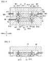
FIG. 4 is a schematic view showing a cross section of a glass opening-and-closing unit according to one embodiment of the invention. -
FIG. 5 is a schematic view showing an action of force applied to the upper glass member according to one embodiment of the invention. -
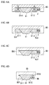
FIG. 6A is a schematic view showing a modified example of a glass opening-and-closing unit according to one embodiment of the invention. -
FIG. 6B is a schematic view showing a modified example of a glass opening-and-closing unit according to one embodiment of the invention. -
FIG. 6C is a schematic view showing a modified example of a glass opening-and-closing unit according to one embodiment of the invention. -
FIG. 6D is a schematic view showing a modified example of a glass opening-and-closing unit according to one embodiment of the invention. - An optical fiber re-coating device A according to the embodiment is an apparatus that removes a coating (intermediate coating) of an optional intermediate portion of an optical fiber and re-coats a portion at which an optical-fiber type optical component was manufactured. Particularly, an optical fiber which is subjected to re-coating by use of the above-mentioned optical fiber re-coating device A has a cladding and a coating that coats the outer-periphery of the cladding which are concentrically formed in order from the center of an axis. Furthermore, the coating of the optical fiber is made of ultraviolet curable resins such as urethane acrylate resins, epoxy acrylate resins, polybutadiene acrylate resins, silicone acrylate resins, polyester acrylate resins.
- As shown in
FIG. 1 , the above-mentioned optical fiber re-coating device A includes: an optical fiber coater M and an optical fiber holder K. - As shown in
FIG. 1 , the optical fiber coater M is constituted of a glass opening-and-closing unit M1 which is configured to include a pair of upper and lower forming members made of a transparent material such as a silica glass. - Glass members G1 and G2 serving as a forming member of the above-described glass opening-and-closing unit M1 include grooves G11 and G21 which are used for re-coating (refer to
FIGS. 2A, 2B ,3A, and 3B ) and provided at the center portions of the surfaces which are butt-jointed to each other. When glass members G1 and G2 are butt-jointed to each other, the aforementioned grooves G11 and G21 form a cavity having a substantially cylindrically-shaped air space. - At this time, the glass members G1 and G2 of the above-described glass opening-and-closing unit M1 are in a state of sandwiching the cavity therebetween at the top and bottom. In the optical fiber coater M, an upper glass member G1 is fixed on an upper mounting table D1 via an adjustment base BD (base). On the other hand, a lower glass member G2 is fixed on a lower mounting table D2 (base). Particularly, the adjustment base BD and the lower mounting table D2 are a base according to the embodiment.
- The mounting table D1 is rotatably supported by a hinge H1 around the edge of the lower mounting table D2. That is, the upper glass member G1 is configured to rotate with respect to the lower glass member G2 so as to be switched between: a state of being butt-jointed to the lower glass member G2 and thereby closing the cavity; and a state of being separated from the lower glass member G2 and thereby opening the cavity.
- Furthermore, a spool Sp and a gate Gt, which are used to inject a liquiform resin, that is, a pre-cured resin into the cavity and which will be described later, are provided on the lower glass member G2 of the glass opening-and-closing unit M1.
- Moreover, a shielding portion made of a chrome (Cr) film is provided on the surface of the lower glass member G2 of the glass opening-and-closing unit M1 which is to be butt-jointed to the upper glass member G1 and on the portion other than the groove G21. The shielding portion is formed by coating the lower glass member G2 with chrome. The shielding portion is used so as to avoid a resin material in the spool Sp and the gate Gt, which will be described later, from being irradiated with ultraviolet light that is used to cause a resin material in the cavity to be cured. Moreover, the above-described glass opening-and-closing unit M1 will be particularly described later.
- A light source (not shown in the figure) is provided in The optical fiber coater M. With respect to the optical fiber coater M, the light source irradiates, for example, the injected resin with ultraviolet light. Subsequently, the resin that is irradiated with ultraviolet light is cured.
- The optical fiber holder K is used to hold an optical fiber that is in a state of being extracted from both sides of the optical fiber coater M when the optical fiber is set on the optical fiber coater M.
- Next, the glass opening-and-closing unit M1 will be particularly described.
- As shown in
FIGS. 1 and4 , the above-described glass opening-and-closing unit M1 includes a pair of glass members G1 and G2, a pair of mounting tables D1 and D2, the hinge H1, the adjustment base BD, a pair of first lateral pressing members ST11 and ST12, and a pair of second lateral pressing members ST21 and ST22. - As shown in
FIGS. 2A, 2B ,3A, and 3B , the glass members G1 and G2 are formed in a trapezoidal shape in a cross section in a direction vertical to a mounting surface BD1 of the adjustment base BD and a mounting surface D21 of the mounting table D2 (refer toFIG. 4 ), and respectively have the grooves G11 and G21 which are used for re-coating and provided on the center portion of the short side of the trapezoidal shape, that is, on the center portions of the surfaces which are butt-jointed to each other. When the above-described forming members are butt-jointed to each other, the above-mentioned grooves G11 and G21 form a cavity having a substantially cylindrically-shaped air space. - Furthermore, the above-mentioned spool Sp and gate Gt in addition to the groove G21 are formed on the lower glass member G2.
- The spool Sp is a flow passage in which a liquiform resin, that is, a pre-cured resin flows and which is penetrated in height direction, and one end thereof is connected to the short side of the aforementioned trapezoidal shape, that is, to the gate Gt formed on the center portion of the surface of the glass member G2 which is to be butt-jointed to the glass member G1. Moreover, the other end of the spool Sp which is opposite to said one end thereof connected to the gate Gt is connected to a resin supply (not shown in the figure) constituted of a pump or the like, and the resin that is to be supplied from the resin supply flows to the gate Gt.
- The gate Gt is a groove formed on the short side of the trapezoidal shape, that is, on the center portion of the surface of the glass member G2 which is to be butt-jointed to the glass member G1, is connected to one end of the spool Sp, and is connected to the groove G21. The resin flows to the gate through the spool Sp. The resin flows toward a cavity formed by the grooves G11 and G21. In the cavity, re-coating the optical fiber is carried out by the resin flowing from the gate Gt thereinto.
- The adjustment base BD is a base to which the upper glass member G1 is fixed, and is fixed on the upper mounting table D1; and the position thereof on the mounting table D1 in the front-back direction (direction from the front side to the back side) is adjusted by positioning screws N41 and N42 which will be described later.
- The paired first lateral pressing members ST11 and ST12 are provided on the mounting surface BD1 of the adjustment base BD and are configured to have inclined surfaces which are to be respectively in surface contact with the two inclined surfaces Sh11 and Sh12 of the glass member G1 having the inclined sides of the trapezoidal shape in the above-described cross section of the upper glass member G1 (refer to
FIGS. 3A and 3B ). The upper glass member G1 is sandwiched between the paired first lateral pressing members ST11 and ST12 from the front side and the back side thereof. - The paired second lateral pressing members ST21 and ST22 are provided on the mounting surface D21 of the lower mounting table D2 and are configured to have inclined surfaces which are to be respectively in surface contact with the two inclined surfaces Sh21 and Sh22 of the glass member G2 having the inclined sides of the trapezoidal shape in the above-described cross section of the lower glass member G2 (refer to
FIGS. 2A and 2B ). The lower glass member G2 is sandwiched between the paired second lateral pressing members ST21 and ST22 from the front side and the back side thereof. Particularly, as shown inFIGS. 1 and4 , of the aforementioned front side and back side, the back side is the side at which the hinge H1 of the glass opening-and-closing unit M1 is provided. On the other hand, the front side is the side opposite to the back side. - For example, holes At1 and At2 for screw are provided along a direction vertical to the mounting surface BD1 of the adjustment base BD on the above-described paired first lateral pressing members ST11 and ST12, respectively. Additionally, on the mounting surface BD1 of the adjustment base BD, threaded holes are provided at the positions, on which the first lateral pressing members ST11 and ST12 are provided, so as to correspond to the holes At1 and At2 for screw of the above-described paired first lateral pressing members ST11 and ST12. The fixing screws N11 and N12 are respectively threadably fitted to the holes At1 and At2 for screw and the threaded holes provided on the adjustment base BD, and the adjustment base BD is thereby coupled to the above-described paired first lateral pressing members ST11 and ST12.
- Furthermore, the adjustment base BD is formed in a container shape such that the center portion thereof is depressed, and the inner bottom surface of the container is the mounting surface BD1. A threaded hole Ah is provided in the direction toward the first lateral pressing member ST12 and on the side surface of the adjustment base BD which is near the first lateral pressing member ST12 (back side). A lateral pressing screw N3 is screwed to the threaded hole Ah, and the first lateral pressing member ST12 is pressed against the upper glass member G1 by the shaft of the lateral pressing screw N3. In particular, since the screw hole At2 for screw of the first lateral pressing member ST12 is formed to be slightly looser than that of the peripheral surface of the shaft of the fixing screw N12, the first lateral pressing member ST12 pressed by the lateral pressing screw N3 presses the upper glass member G1. As a result, as shown in
FIG. 5 , the glass member G1 is pressed in the direction toward the upper mounting table D1 and thereby tightly fixed to the adjustment base BD. - Furthermore, the mounting table D1 is also is formed in a container shape such that the center portion thereof is depressed and accommodates the adjustment base BD in the container thereof. Threaded holes Af1 and Af2 are provided in the direction toward the adjustment base BD and on the two side surfaces of the mounting table D1 which are near the first lateral pressing member ST11 (front side) and the first lateral pressing member ST12 (back side). The positioning screws N41 and N42 are threadably fitted into the threaded holes Af1 and Af2, and the adjustment base BD is pressed by the positioning screws N41 and N42. As a result, the position of the adjustment base BD is adjusted on the mounting table D1 in the front-back direction (direction from the front side to the back side) is adjusted.
- Moreover, holes As1 and As2 for screw are provided along a direction vertical to the mounting surface D21 of the lower mounting table D2 on the aforementioned paired second lateral pressing members ST21 and ST22, respectively. Additionally, on the mounting surface D21 of the lower mounting table D2, threaded holes are provided at the positions, on which the second lateral pressing members ST21 and ST22 are provided, so as to correspond to the holes As1 and As2 for screw of the above-described paired second lateral pressing members ST21 and ST22. The fixing screws N21 and N22 are respectively threadably fitted to the holes As1 and As2 for screw and the threaded holes provided on the lower mounting table D2, and the lower mounting table D2 is thereby coupled to the above-described paired second lateral pressing members ST21 and ST22.
- Furthermore, the lower mounting table D2 is formed in a container shape such that the center portion thereof is depressed, and the inner bottom surface of the container is the mounting surface D21. A threaded hole Ag is provided in the direction toward the second lateral pressing member ST21 and on the side surface of the lower mounting table D2 which is near the second lateral pressing member ST21 (front side). A lateral pressing screw N5 is screwed to the threaded hole Ag, and the second lateral pressing member ST21 is pressed against the lower glass member G2 by the shaft of the lateral pressing screw N5. In particular, since the hole As1 for screw of the second lateral pressing member ST21 is formed to be slightly looser than that of the peripheral surface of the shaft of the fixing screw N21, the second lateral pressing member ST21 pressed by the lateral pressing screw N5 presses the lower glass member G2. As a result, the glass member G2 is pressed in the direction toward the lower mounting table D2 and thereby tightly fixed to the lower mounting table D2.
- In addition, regarding a modified example of the embodiment, as shown in
FIG. 6A , by providing a force-applying means F such as a spring between the side surface of the adjustment base BD and the first lateral pressing member ST12 instead of the above-described lateral pressing screw N3, the first lateral pressing member ST12 may be pressed against the glass member G1 by the force-applying means F. - Furthermore, regarding a modified example of the embodiment, as shown in
FIG. 6B , without fixing the aforementioned first lateral pressing members ST11 and ST12 to the adjustment base BD by the fixing screws N11 and N12, sandwich-holding mechanisms KJ1 and KJ2 that holds the aforementioned first lateral pressing members ST11 and ST12 in the vertical direction may be provided in the adjustment base BD. - Moreover, regarding a modified example of the embodiment, as shown in
FIG. 6C , the upper glass member G1 is pressed only by the above-mentioned first lateral pressing member ST12, and a lateral pressing mechanism BD2 which is near the first lateral pressing member ST11 (front side) and which comes into surface contact with the inclined surface Sh11 of the upper glass member G1 may be provided in the adjustment base BD. - Additionally, regarding a modified example of the embodiment, as shown in
FIG. 6D , the first lateral pressing member ST32 having an inclined surface that comes into surface contact with the inclined surface Sh12 of the upper glass member G1 is provided instead of the first lateral pressing member ST12, the inclined surface Sh12 of the upper glass member G1 may be pressed in a direction vertical thereto toward the upper glass member G1 by the first lateral pressing member ST32 and by a lateral pressing screw N6 screwed to the adjustment base BD. Also, by preparing a first lateral pressing member that is the same as the first lateral pressing member ST32 and using the first lateral pressing member, the glass member G1 may tightly fixed to the adjustment base BD with respect to the inclined surface Sh11 of the upper glass member G1. - Particularly, the above-described fixing screws N11 and N12, N21, and N22, the lateral pressing screw N3, the positioning screws N41 and N42, the lateral pressing screw N5, and the lateral pressing screw N6 are not shown in
FIGS. 4, 5 ,6A, 6B, 6C, and 6D ; however, a plurality thereof are provided in the width direction of the optical fiber re-coating device A. - According to the above-described embodiment, the paired glass members G1 and G2 are formed in a trapezoidal shape in the cross section in a direction vertical to the mounting surface BD1 of the adjustment base BD and the mounting surface D21 of the mounting table D2 (refer to
FIG. 4 ), the grooves G11 and G21 are provided on the short side of the trapezoidal shape, the inclined surfaces Sh11, Sh12, Sh21, and Sh22 of the glass member including the inclined side of the trapezoidal shape are pressed, and the glass members G1 and G2 can thereby be fixed thereto without occurrence of warpage of the glass members G1 and G2 and without providing threaded holes the glass members G1 and G2. - Moreover, according to the embodiment, as described above, it is not necessary to provide threaded holes on the glass members G1 and G2. Consequently, since the glass members G1 and G2 can be downsized, it is possible to reduce the material cost of pure quartz.
- Furthermore, according to the embodiment, as a result of reducing the size of the glass members G1 and G2, the rigidity in the glass members G1 and G2 is improved.
- Additionally, according to the embodiment, as described above, since it is not necessary to provide threaded holes on the glass members G1 and G2 and grinding machining thereof with respect to the glass members G1 and G2 is not required, a damage to the glass members G1 and G2 is reduced, and the reliability thereof is improved.
- Also, according to the embodiment, as described above, since it is not necessary to provide threaded holes on the glass members G1 and G2 and grinding machining therefor is not required, the processing cost is reduced and can be inexpensive.
- In addition, according to the embodiment, the glass members G1 and G2 are not locally and directly pressed by the screws, and a localized deformation of the glass members G1 and G2 does not occur.
- Moreover, according to the embodiment, as a result of precisely polishing the mounting surface BD1 of the adjustment base BD, the mounting surface D21 of the mounting table D2, and the bottom surface of the glass members G1 and G2, it is possible to further reduce warpage of the glass members G1 and G2.
- Additionally, according to the embodiment, since the glass members G1 and G2 are tightly fixed onto the mounting surface BD1 of the adjustment base BD and the mounting surface D21 of the mounting table D2, respectively, it is possible to reduce displacement of the glass members G1 and G2 due to impact during operation of opening and closing the glass opening-and-closing unit M1.
- An embodiment of the invention is described above; however, the invention is not limited to the above-mentioned embodiment, for example, the following modification may be considered.
- (1) In the above-mentioned embodiment, both the paired glass members G1 and G2 are formed in a trapezoidal shape in the cross section and are fixed onto the mounting surface BD1 of the adjustment base BD and the mounting surface D21 of the mounting table D2, respectively, due to the inclined surfaces Sh11, Sh12, Sh21, and Sh22 being pressed; however, it is only necessary that at least one of the paired glass members G1 and G2 is formed in a trapezoidal shape in the above-mentioned cross section and is fixed onto the mounting surface due to the inclined surface thereof being pressed.
Moreover, both the glass members G1 and G2 are formed in a trapezoidal shape in cross section having two inclined sides; however, it may not be formed in a trapezoidal shape having two inclined sides, it may be formed in a trapezoidal shape having one inclined side and the other side that is a straight line vertical to a bottom side, and a lateral pressing member may be provided on the inclined surface having said one inclined side. In this case, it is only necessary to allow the side surface of the adjustment base BD to come into contact with the flat surface including the straight line vertical to the bottom side of the trapezoidal shape. Also, the present invention is not limited to the aforementioned trapezoidal shape as long as the above-described cross section is formed in a shape having a side inclined with respect to the mounting surface BD1 of the adjustment base BD or the mounting surface D21 of the mounting table D2. - (2) In the above-mentioned embodiment, the lateral pressing screws N3, N5, and N6 directly press the first lateral pressing member ST12, the second lateral pressing member ST22, and the first lateral pressing member ST32; however, plate-shaped members are provided: between the lateral pressing screws N3 and the first lateral pressing member ST12; between the lateral pressing screws N5 and the second lateral pressing member ST22; and between the lateral pressing screws N6 and the first lateral pressing member ST32, and pressing forces of the lateral pressing screws N3, N5, and N6 may be entirely applied to the first lateral pressing member ST12, the second lateral pressing member ST22, and the first lateral pressing member ST32.
- A ··· optical fiber re-coating device, M ··· optical fiber coater, K ··· optical fiber holder, M1 ··· glass opening-and-closing unit, G1, G2 ··· glass member, D1, D2 ··· mounting table (base), H1 ··· hinge, Sp ··· spool, Gt ··· gate, ST11, ST12 ··· first lateral pressing member, ST21, ST22...second lateral pressing member, At1, At2...hole for screw, N11, N 12... fixing screw, As1, As2... hole for screw, N21, N22... fixing screw, Ah...threaded hole, N3... lateral pressing screw, Af1, Af2...threaded hole, N41, N42...positioning screw, Ag...threaded hole, N5...lateral pressing screw, Sh11, Sh12...inclined surface, Sh21, Sh22...inclined surface, BD...adjustment base, F...force-applying means, KJ1, KJ2...sandwich-holding mechanism, BD2...lateral pressing mechanism, ST32...first lateral pressing member, N6...lateral pressing screw
Claims (4)
- An optical fiber re-coating device comprising an optical fiber coater that cures resin and coats a coating-removed portion of an optical fiber therewith, the optical fiber coater comprising:a pair of glass members having grooves formed thereon; and two bases on which the respective glass members are provided, whereina hollow that is used to coat an optical fiber is formed by matching the grooves of the paired glass members, and whereinat least one of the paired glass members is formed in a trapezoidal shape in a cross section in a direction vertical to mounting surfaces of the bases,the groove is provided on a short side of the trapezoidal shape, andan inclined surface of the glass member including an inclined side of the trapezoidal shape is pressed, and the glass member is thereby fixed to the base.
- The optical fiber re-coating device according to claim 1, wherein
each of the paired glass members is formed in a trapezoidal shape in a cross section in a direction vertical to the mounting surfaces of the bases, and
an inclined surface of the glass member including an inclined side of the trapezoidal shape is pressed, and the glass member is thereby fixed to the base. - The optical fiber re-coating device according to claim 1 or claim 2, wherein
the optical fiber coater further comprises a lateral pressing member that has inclined surfaces that come into surface contact with the inclined surface of the glass member,
the lateral pressing member corresponds to at least one of the two inclined surfaces of the glass member, is provided on the mounting surface of the base, and is pressed against the glass member. - The optical fiber re-coating device according to claim 1 or claim 2, wherein
the optical fiber coater further comprises a lateral pressing member that has inclined surfaces that come into surface contact with the inclined surface of the glass member,
the lateral pressing member corresponds to at least one of the two inclined surfaces of the glass member, is provided on the base, and is pressed against the glass member in a direction vertical to the inclined surface of the glass member.
Applications Claiming Priority (2)
| Application Number | Priority Date | Filing Date | Title |
|---|---|---|---|
| JP2014202272A JP5690018B1 (en) | 2014-09-30 | 2014-09-30 | Optical fiber re-coating equipment |
| PCT/JP2014/076591 WO2016051598A1 (en) | 2014-09-30 | 2014-10-03 | Optical fiber recoating device |
Publications (3)
| Publication Number | Publication Date |
|---|---|
| EP3023215A1 true EP3023215A1 (en) | 2016-05-25 |
| EP3023215A4 EP3023215A4 (en) | 2017-04-19 |
| EP3023215B1 EP3023215B1 (en) | 2018-06-27 |
Family
ID=52823345
Family Applications (1)
| Application Number | Title | Priority Date | Filing Date |
|---|---|---|---|
| EP14896959.5A Active EP3023215B1 (en) | 2014-09-30 | 2014-10-03 | Optical fiber recoating device |
Country Status (5)
| Country | Link |
|---|---|
| US (1) | US10532503B2 (en) |
| EP (1) | EP3023215B1 (en) |
| JP (1) | JP5690018B1 (en) |
| CN (1) | CN105658393B (en) |
| WO (1) | WO2016051598A1 (en) |
Families Citing this family (1)
| Publication number | Priority date | Publication date | Assignee | Title |
|---|---|---|---|---|
| CN113799344B (en) * | 2021-09-29 | 2023-06-16 | 安徽福耐沃包装科技有限公司 | Eye shadow box injection mold and manufacturing method thereof |
Family Cites Families (11)
| Publication number | Priority date | Publication date | Assignee | Title |
|---|---|---|---|---|
| JPH0353527Y2 (en) | 1985-04-12 | 1991-11-22 | ||
| JPH0346894Y2 (en) * | 1986-12-16 | 1991-10-04 | ||
| JPH0368905A (en) * | 1989-08-08 | 1991-03-25 | Fujikura Ltd | Method and device for coating fusion spliced part of optical fiber |
| JPH0516189Y2 (en) | 1989-09-29 | 1993-04-28 | ||
| JPH06148453A (en) * | 1992-11-11 | 1994-05-27 | Fujikura Ltd | Recoating device for wire |
| AU7336596A (en) | 1995-10-27 | 1997-05-15 | Hoya Corporation | Optical fiber fixing member and method of production thereof |
| JP2002072000A (en) | 2000-08-23 | 2002-03-12 | Furukawa Electric Co Ltd:The | Optical fiber coating equipment |
| JP4794778B2 (en) | 2001-09-14 | 2011-10-19 | 古河電気工業株式会社 | Optical fiber coating equipment |
| JP3951801B2 (en) | 2002-05-17 | 2007-08-01 | 住友電気工業株式会社 | Fusion splicing optical fiber processing method and conveying jig |
| JP2004341387A (en) * | 2003-05-19 | 2004-12-02 | Fujikura Ltd | Optical fiber recoating equipment |
| JP2006292674A (en) * | 2005-04-14 | 2006-10-26 | Fujikura Ltd | Optical power monitoring method, optical power monitoring apparatus, and optical device |
-
2014
- 2014-09-30 JP JP2014202272A patent/JP5690018B1/en active Active
- 2014-10-03 CN CN201480038749.3A patent/CN105658393B/en active Active
- 2014-10-03 US US14/905,163 patent/US10532503B2/en active Active
- 2014-10-03 EP EP14896959.5A patent/EP3023215B1/en active Active
- 2014-10-03 WO PCT/JP2014/076591 patent/WO2016051598A1/en not_active Ceased
Also Published As
| Publication number | Publication date |
|---|---|
| JP2016069245A (en) | 2016-05-09 |
| CN105658393B (en) | 2017-11-03 |
| CN105658393A (en) | 2016-06-08 |
| JP5690018B1 (en) | 2015-03-25 |
| WO2016051598A1 (en) | 2016-04-07 |
| US20160221240A1 (en) | 2016-08-04 |
| EP3023215A4 (en) | 2017-04-19 |
| US10532503B2 (en) | 2020-01-14 |
| EP3023215B1 (en) | 2018-06-27 |
Similar Documents
| Publication | Publication Date | Title |
|---|---|---|
| US20130300974A1 (en) | Liquid crystal display device and manufacturing method thereof | |
| US9005387B2 (en) | Method for fabricating a window member of the display device of a portable terminal | |
| TWI668098B (en) | Imprinting device | |
| KR102383744B1 (en) | Substrate dividing method and scribe apparatus | |
| US20090225050A1 (en) | Touch panel, liquid crystal display apparatus, and method for manufacturing thereof | |
| TWI532583B (en) | Transfer printing apparatus and manufacturing method of light guiding film | |
| EP3023215B1 (en) | Optical fiber recoating device | |
| KR20200003899A (en) | Manufacturing Method of Transparent Panel, Manufacturing Method of Optical Device | |
| WO2017080037A1 (en) | Backlight assembly, backlight module, and display apparatus | |
| JP5366452B2 (en) | Molding method and molding apparatus for molded product | |
| US8297962B2 (en) | Molding machine and method for forming optical film | |
| TW201344293A (en) | Substrate adhering method and adhering device | |
| US20140084520A1 (en) | Manufacturing apparatus of display device, and manufacturing method of display device | |
| CN206133135U (en) | Manufacturing device | |
| KR20190019868A (en) | Method for manufacturing OCA with non-rectagular-shaped cross section and apparatus for the same | |
| TWI702149B (en) | Transfer apparatus and transfer method | |
| CN118457066A (en) | A UV curing device and printing curing method for realizing light-shielding printing technology | |
| KR20100041911A (en) | Light guide for backlight unit and manufacturing method thereof | |
| CN115837340A (en) | Manufacturing method of dispensing device and optical fiber transmission module | |
| JPH10274946A (en) | Production of liquid crystal panel | |
| US9839934B2 (en) | Optical fiber re-coating device | |
| CN214205728U (en) | Customized white card module | |
| KR100936923B1 (en) | Light guide plate using ultraviolet transferring and manufacturing method thereof | |
| CN223864337U (en) | A leveling device for use in UV curing printers | |
| CN105980910A (en) | Method for manufacturing an ophthalmic lens equipped with an insert |
Legal Events
| Date | Code | Title | Description |
|---|---|---|---|
| PUAI | Public reference made under article 153(3) epc to a published international application that has entered the european phase |
Free format text: ORIGINAL CODE: 0009012 |
|
| 17P | Request for examination filed |
Effective date: 20160113 |
|
| AK | Designated contracting states |
Kind code of ref document: A1 Designated state(s): AL AT BE BG CH CY CZ DE DK EE ES FI FR GB GR HR HU IE IS IT LI LT LU LV MC MK MT NL NO PL PT RO RS SE SI SK SM TR |
|
| AX | Request for extension of the european patent |
Extension state: BA ME |
|
| STAA | Information on the status of an ep patent application or granted ep patent |
Free format text: STATUS: REQUEST FOR EXAMINATION WAS MADE |
|
| R17P | Request for examination filed (corrected) |
Effective date: 20160113 |
|
| A4 | Supplementary search report drawn up and despatched |
Effective date: 20170317 |
|
| RIC1 | Information provided on ipc code assigned before grant |
Ipc: G02B 6/44 20060101ALI20170313BHEP Ipc: B29C 45/17 20060101AFI20170313BHEP Ipc: C03C 25/12 20060101ALI20170313BHEP |
|
| DAX | Request for extension of the european patent (deleted) | ||
| REG | Reference to a national code |
Ref country code: DE Ref legal event code: R079 Ref document number: 602014027726 Country of ref document: DE Free format text: PREVIOUS MAIN CLASS: B29C0039100000 Ipc: B29C0045170000 |
|
| GRAP | Despatch of communication of intention to grant a patent |
Free format text: ORIGINAL CODE: EPIDOSNIGR1 |
|
| STAA | Information on the status of an ep patent application or granted ep patent |
Free format text: STATUS: GRANT OF PATENT IS INTENDED |
|
| RIC1 | Information provided on ipc code assigned before grant |
Ipc: B29C 45/17 20060101AFI20180110BHEP Ipc: C03C 25/12 20060101ALI20180110BHEP Ipc: G02B 6/44 20060101ALI20180110BHEP |
|
| INTG | Intention to grant announced |
Effective date: 20180207 |
|
| GRAS | Grant fee paid |
Free format text: ORIGINAL CODE: EPIDOSNIGR3 |
|
| GRAA | (expected) grant |
Free format text: ORIGINAL CODE: 0009210 |
|
| STAA | Information on the status of an ep patent application or granted ep patent |
Free format text: STATUS: THE PATENT HAS BEEN GRANTED |
|
| AK | Designated contracting states |
Kind code of ref document: B1 Designated state(s): AL AT BE BG CH CY CZ DE DK EE ES FI FR GB GR HR HU IE IS IT LI LT LU LV MC MK MT NL NO PL PT RO RS SE SI SK SM TR |
|
| REG | Reference to a national code |
Ref country code: GB Ref legal event code: FG4D |
|
| REG | Reference to a national code |
Ref country code: AT Ref legal event code: REF Ref document number: 1011914 Country of ref document: AT Kind code of ref document: T Effective date: 20180715 |
|
| REG | Reference to a national code |
Ref country code: DE Ref legal event code: R096 Ref document number: 602014027726 Country of ref document: DE |
|
| REG | Reference to a national code |
Ref country code: IE Ref legal event code: FG4D |
|
| REG | Reference to a national code |
Ref country code: FR Ref legal event code: PLFP Year of fee payment: 5 |
|
| PG25 | Lapsed in a contracting state [announced via postgrant information from national office to epo] |
Ref country code: NO Free format text: LAPSE BECAUSE OF FAILURE TO SUBMIT A TRANSLATION OF THE DESCRIPTION OR TO PAY THE FEE WITHIN THE PRESCRIBED TIME-LIMIT Effective date: 20180927 Ref country code: LT Free format text: LAPSE BECAUSE OF FAILURE TO SUBMIT A TRANSLATION OF THE DESCRIPTION OR TO PAY THE FEE WITHIN THE PRESCRIBED TIME-LIMIT Effective date: 20180627 Ref country code: SE Free format text: LAPSE BECAUSE OF FAILURE TO SUBMIT A TRANSLATION OF THE DESCRIPTION OR TO PAY THE FEE WITHIN THE PRESCRIBED TIME-LIMIT Effective date: 20180627 Ref country code: FI Free format text: LAPSE BECAUSE OF FAILURE TO SUBMIT A TRANSLATION OF THE DESCRIPTION OR TO PAY THE FEE WITHIN THE PRESCRIBED TIME-LIMIT Effective date: 20180627 Ref country code: BG Free format text: LAPSE BECAUSE OF FAILURE TO SUBMIT A TRANSLATION OF THE DESCRIPTION OR TO PAY THE FEE WITHIN THE PRESCRIBED TIME-LIMIT Effective date: 20180927 |
|
| REG | Reference to a national code |
Ref country code: NL Ref legal event code: MP Effective date: 20180627 |
|
| REG | Reference to a national code |
Ref country code: LT Ref legal event code: MG4D |
|
| PG25 | Lapsed in a contracting state [announced via postgrant information from national office to epo] |
Ref country code: HR Free format text: LAPSE BECAUSE OF FAILURE TO SUBMIT A TRANSLATION OF THE DESCRIPTION OR TO PAY THE FEE WITHIN THE PRESCRIBED TIME-LIMIT Effective date: 20180627 Ref country code: LV Free format text: LAPSE BECAUSE OF FAILURE TO SUBMIT A TRANSLATION OF THE DESCRIPTION OR TO PAY THE FEE WITHIN THE PRESCRIBED TIME-LIMIT Effective date: 20180627 Ref country code: RS Free format text: LAPSE BECAUSE OF FAILURE TO SUBMIT A TRANSLATION OF THE DESCRIPTION OR TO PAY THE FEE WITHIN THE PRESCRIBED TIME-LIMIT Effective date: 20180627 Ref country code: GR Free format text: LAPSE BECAUSE OF FAILURE TO SUBMIT A TRANSLATION OF THE DESCRIPTION OR TO PAY THE FEE WITHIN THE PRESCRIBED TIME-LIMIT Effective date: 20180928 |
|
| REG | Reference to a national code |
Ref country code: AT Ref legal event code: MK05 Ref document number: 1011914 Country of ref document: AT Kind code of ref document: T Effective date: 20180627 |
|
| PG25 | Lapsed in a contracting state [announced via postgrant information from national office to epo] |
Ref country code: NL Free format text: LAPSE BECAUSE OF FAILURE TO SUBMIT A TRANSLATION OF THE DESCRIPTION OR TO PAY THE FEE WITHIN THE PRESCRIBED TIME-LIMIT Effective date: 20180627 |
|
| PG25 | Lapsed in a contracting state [announced via postgrant information from national office to epo] |
Ref country code: EE Free format text: LAPSE BECAUSE OF FAILURE TO SUBMIT A TRANSLATION OF THE DESCRIPTION OR TO PAY THE FEE WITHIN THE PRESCRIBED TIME-LIMIT Effective date: 20180627 Ref country code: IS Free format text: LAPSE BECAUSE OF FAILURE TO SUBMIT A TRANSLATION OF THE DESCRIPTION OR TO PAY THE FEE WITHIN THE PRESCRIBED TIME-LIMIT Effective date: 20181027 Ref country code: PL Free format text: LAPSE BECAUSE OF FAILURE TO SUBMIT A TRANSLATION OF THE DESCRIPTION OR TO PAY THE FEE WITHIN THE PRESCRIBED TIME-LIMIT Effective date: 20180627 Ref country code: SK Free format text: LAPSE BECAUSE OF FAILURE TO SUBMIT A TRANSLATION OF THE DESCRIPTION OR TO PAY THE FEE WITHIN THE PRESCRIBED TIME-LIMIT Effective date: 20180627 Ref country code: RO Free format text: LAPSE BECAUSE OF FAILURE TO SUBMIT A TRANSLATION OF THE DESCRIPTION OR TO PAY THE FEE WITHIN THE PRESCRIBED TIME-LIMIT Effective date: 20180627 Ref country code: CZ Free format text: LAPSE BECAUSE OF FAILURE TO SUBMIT A TRANSLATION OF THE DESCRIPTION OR TO PAY THE FEE WITHIN THE PRESCRIBED TIME-LIMIT Effective date: 20180627 Ref country code: AT Free format text: LAPSE BECAUSE OF FAILURE TO SUBMIT A TRANSLATION OF THE DESCRIPTION OR TO PAY THE FEE WITHIN THE PRESCRIBED TIME-LIMIT Effective date: 20180627 |
|
| PG25 | Lapsed in a contracting state [announced via postgrant information from national office to epo] |
Ref country code: SM Free format text: LAPSE BECAUSE OF FAILURE TO SUBMIT A TRANSLATION OF THE DESCRIPTION OR TO PAY THE FEE WITHIN THE PRESCRIBED TIME-LIMIT Effective date: 20180627 Ref country code: ES Free format text: LAPSE BECAUSE OF FAILURE TO SUBMIT A TRANSLATION OF THE DESCRIPTION OR TO PAY THE FEE WITHIN THE PRESCRIBED TIME-LIMIT Effective date: 20180627 Ref country code: IT Free format text: LAPSE BECAUSE OF FAILURE TO SUBMIT A TRANSLATION OF THE DESCRIPTION OR TO PAY THE FEE WITHIN THE PRESCRIBED TIME-LIMIT Effective date: 20180627 |
|
| REG | Reference to a national code |
Ref country code: DE Ref legal event code: R097 Ref document number: 602014027726 Country of ref document: DE |
|
| PLBE | No opposition filed within time limit |
Free format text: ORIGINAL CODE: 0009261 |
|
| STAA | Information on the status of an ep patent application or granted ep patent |
Free format text: STATUS: NO OPPOSITION FILED WITHIN TIME LIMIT |
|
| PG25 | Lapsed in a contracting state [announced via postgrant information from national office to epo] |
Ref country code: DK Free format text: LAPSE BECAUSE OF FAILURE TO SUBMIT A TRANSLATION OF THE DESCRIPTION OR TO PAY THE FEE WITHIN THE PRESCRIBED TIME-LIMIT Effective date: 20180627 |
|
| REG | Reference to a national code |
Ref country code: CH Ref legal event code: PL |
|
| 26N | No opposition filed |
Effective date: 20190328 |
|
| REG | Reference to a national code |
Ref country code: BE Ref legal event code: MM Effective date: 20181031 |
|
| PG25 | Lapsed in a contracting state [announced via postgrant information from national office to epo] |
Ref country code: MC Free format text: LAPSE BECAUSE OF FAILURE TO SUBMIT A TRANSLATION OF THE DESCRIPTION OR TO PAY THE FEE WITHIN THE PRESCRIBED TIME-LIMIT Effective date: 20180627 Ref country code: LU Free format text: LAPSE BECAUSE OF NON-PAYMENT OF DUE FEES Effective date: 20181003 |
|
| REG | Reference to a national code |
Ref country code: IE Ref legal event code: MM4A |
|
| PG25 | Lapsed in a contracting state [announced via postgrant information from national office to epo] |
Ref country code: BE Free format text: LAPSE BECAUSE OF NON-PAYMENT OF DUE FEES Effective date: 20181031 Ref country code: SI Free format text: LAPSE BECAUSE OF FAILURE TO SUBMIT A TRANSLATION OF THE DESCRIPTION OR TO PAY THE FEE WITHIN THE PRESCRIBED TIME-LIMIT Effective date: 20180627 Ref country code: LI Free format text: LAPSE BECAUSE OF NON-PAYMENT OF DUE FEES Effective date: 20181031 Ref country code: CH Free format text: LAPSE BECAUSE OF NON-PAYMENT OF DUE FEES Effective date: 20181031 |
|
| PG25 | Lapsed in a contracting state [announced via postgrant information from national office to epo] |
Ref country code: IE Free format text: LAPSE BECAUSE OF NON-PAYMENT OF DUE FEES Effective date: 20181003 |
|
| PG25 | Lapsed in a contracting state [announced via postgrant information from national office to epo] |
Ref country code: AL Free format text: LAPSE BECAUSE OF FAILURE TO SUBMIT A TRANSLATION OF THE DESCRIPTION OR TO PAY THE FEE WITHIN THE PRESCRIBED TIME-LIMIT Effective date: 20180627 |
|
| PG25 | Lapsed in a contracting state [announced via postgrant information from national office to epo] |
Ref country code: MT Free format text: LAPSE BECAUSE OF NON-PAYMENT OF DUE FEES Effective date: 20181003 |
|
| PG25 | Lapsed in a contracting state [announced via postgrant information from national office to epo] |
Ref country code: TR Free format text: LAPSE BECAUSE OF FAILURE TO SUBMIT A TRANSLATION OF THE DESCRIPTION OR TO PAY THE FEE WITHIN THE PRESCRIBED TIME-LIMIT Effective date: 20180627 |
|
| PG25 | Lapsed in a contracting state [announced via postgrant information from national office to epo] |
Ref country code: PT Free format text: LAPSE BECAUSE OF FAILURE TO SUBMIT A TRANSLATION OF THE DESCRIPTION OR TO PAY THE FEE WITHIN THE PRESCRIBED TIME-LIMIT Effective date: 20180627 |
|
| PG25 | Lapsed in a contracting state [announced via postgrant information from national office to epo] |
Ref country code: MK Free format text: LAPSE BECAUSE OF NON-PAYMENT OF DUE FEES Effective date: 20180627 Ref country code: CY Free format text: LAPSE BECAUSE OF FAILURE TO SUBMIT A TRANSLATION OF THE DESCRIPTION OR TO PAY THE FEE WITHIN THE PRESCRIBED TIME-LIMIT Effective date: 20180627 Ref country code: HU Free format text: LAPSE BECAUSE OF FAILURE TO SUBMIT A TRANSLATION OF THE DESCRIPTION OR TO PAY THE FEE WITHIN THE PRESCRIBED TIME-LIMIT; INVALID AB INITIO Effective date: 20141003 |
|
| P01 | Opt-out of the competence of the unified patent court (upc) registered |
Effective date: 20230512 |
|
| PGFP | Annual fee paid to national office [announced via postgrant information from national office to epo] |
Ref country code: GB Payment date: 20250828 Year of fee payment: 12 |
|
| PGFP | Annual fee paid to national office [announced via postgrant information from national office to epo] |
Ref country code: FR Payment date: 20250908 Year of fee payment: 12 |
|
| PGFP | Annual fee paid to national office [announced via postgrant information from national office to epo] |
Ref country code: DE Payment date: 20250902 Year of fee payment: 12 |