EP3023168A1 - Press molding method - Google Patents
Press molding method Download PDFInfo
- Publication number
- EP3023168A1 EP3023168A1 EP14826390.8A EP14826390A EP3023168A1 EP 3023168 A1 EP3023168 A1 EP 3023168A1 EP 14826390 A EP14826390 A EP 14826390A EP 3023168 A1 EP3023168 A1 EP 3023168A1
- Authority
- EP
- European Patent Office
- Prior art keywords
- vertical wall
- wall portion
- blank
- wrinkle
- crack
- Prior art date
- Legal status (The legal status is an assumption and is not a legal conclusion. Google has not performed a legal analysis and makes no representation as to the accuracy of the status listed.)
- Granted
Links
Images




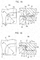
Classifications
-
- B—PERFORMING OPERATIONS; TRANSPORTING
- B21—MECHANICAL METAL-WORKING WITHOUT ESSENTIALLY REMOVING MATERIAL; PUNCHING METAL
- B21D—WORKING OR PROCESSING OF SHEET METAL OR METAL TUBES, RODS OR PROFILES WITHOUT ESSENTIALLY REMOVING MATERIAL; PUNCHING METAL
- B21D22/00—Shaping without cutting, by stamping, spinning, or deep-drawing
- B21D22/02—Stamping using rigid devices or tools
-
- B—PERFORMING OPERATIONS; TRANSPORTING
- B21—MECHANICAL METAL-WORKING WITHOUT ESSENTIALLY REMOVING MATERIAL; PUNCHING METAL
- B21D—WORKING OR PROCESSING OF SHEET METAL OR METAL TUBES, RODS OR PROFILES WITHOUT ESSENTIALLY REMOVING MATERIAL; PUNCHING METAL
- B21D19/00—Flanging or other edge treatment, e.g. of tubes
- B21D19/08—Flanging or other edge treatment, e.g. of tubes by single or successive action of pressing tools, e.g. vice jaws
-
- B—PERFORMING OPERATIONS; TRANSPORTING
- B21—MECHANICAL METAL-WORKING WITHOUT ESSENTIALLY REMOVING MATERIAL; PUNCHING METAL
- B21D—WORKING OR PROCESSING OF SHEET METAL OR METAL TUBES, RODS OR PROFILES WITHOUT ESSENTIALLY REMOVING MATERIAL; PUNCHING METAL
- B21D22/00—Shaping without cutting, by stamping, spinning, or deep-drawing
- B21D22/20—Deep-drawing
-
- B—PERFORMING OPERATIONS; TRANSPORTING
- B21—MECHANICAL METAL-WORKING WITHOUT ESSENTIALLY REMOVING MATERIAL; PUNCHING METAL
- B21D—WORKING OR PROCESSING OF SHEET METAL OR METAL TUBES, RODS OR PROFILES WITHOUT ESSENTIALLY REMOVING MATERIAL; PUNCHING METAL
- B21D25/00—Working sheet metal of limited length by stretching, e.g. for straightening
-
- B—PERFORMING OPERATIONS; TRANSPORTING
- B21—MECHANICAL METAL-WORKING WITHOUT ESSENTIALLY REMOVING MATERIAL; PUNCHING METAL
- B21D—WORKING OR PROCESSING OF SHEET METAL OR METAL TUBES, RODS OR PROFILES WITHOUT ESSENTIALLY REMOVING MATERIAL; PUNCHING METAL
- B21D5/00—Bending sheet metal along straight lines, e.g. to form simple curves
- B21D5/06—Bending sheet metal along straight lines, e.g. to form simple curves by drawing procedure making use of dies or forming-rollers, e.g. making profiles
-
- B—PERFORMING OPERATIONS; TRANSPORTING
- B21—MECHANICAL METAL-WORKING WITHOUT ESSENTIALLY REMOVING MATERIAL; PUNCHING METAL
- B21D—WORKING OR PROCESSING OF SHEET METAL OR METAL TUBES, RODS OR PROFILES WITHOUT ESSENTIALLY REMOVING MATERIAL; PUNCHING METAL
- B21D53/00—Making other particular articles
- B21D53/88—Making other particular articles other parts for vehicles, e.g. cowlings, mudguards
Definitions
- the present invention relates to a technique of press forming for forming a material into a press-formed part having a curved vertical wall portion, such as a curved channel part.
- the present invention is a technique particularly preferable for press forming on a portion of a curved portion of a vertical wall portion that is deformed in a manner of stretch flange deformation by forming.
- a channel part with a simple shape including a vertical wall portion and a top portion continuous to the vertical wall portion but not including a curved portion in the vertical wall portion is manufactured by stamping.
- a flanged channel part is manufactured by deep drawing.
- a blank (a flat-sheet-shaped processing material) is arranged on a punch, and the blank is bent with a die, to obtain a product shape.
- a blank may be pinched and held by the punch and a pad.
- a blank holder is arranged at a position corresponding to a flange portion, a blank is arranged on a punch and the blank holder, and a die is arranged above the blank. Then, by lowering the die, the blank is held by the die and the blank holder, and the blank is bent while a load of a proper tensile force is applied to the blank. At this time, the material (the blank) is largely drawn into an area between the punch and the die as the result that the material is held by the die and the blank holder forms a vertical wall portion. Hence, the vertical wall portion is easily formed even when the material has a low ductility.
- a method of adjusting a tensile force there may be a method of changing a holding force (a cushion pressure) of holding the blank by the die and the blank holder, and a method of arranging a bead at the holding position. If the tensile force applied to the blank is too weak, the material excessively flows to the vertical wall portion, and a wrinkle (a material excess) is likely generated. In contrast, if the tensile force is excessive, the amount of the material flowing to the vertical wall portion is reduced. At forming the vertical wall portion the material is required to be stretched and a crack may be generated if the material has a low ductility.
- a press-formed part for a vehicle includes a curved channel part having a curved portion in a vertical wall portion (for example, a lower arm part shown in Fig. 10 ), and a curved channel part having a flange portion (for example, a center pillar part shown in Fig. 3 ).
- a curved channel part having a curved portion in a vertical wall portion is manufactured by stamping, when a material is drawn into a vertical-wall-portion formation space of a die and the vertical wall portion is formed, the line length of the material is sufficient at the curved portion, and the material is stretched and deformed in a circumferential direction of the curved portion.
- This deformation is called "stretch flange deformation.”
- the stretch flange deformation becomes larger as the material is drawn into the vertical-wall-portion formation space from a position more separated from the curved portion (for example, a portion 42a in Fig. 10 or a portion 22a in Fig. 3 ).
- a crack may be generated.
- the crack caused by stretch flange deformation is a problem particularly for a material, such as a steel sheet with a high strength, the material which likely has an insufficient ductility. Also, even in a case of a material other than the steel sheet, if the material has a low ductility, a crack caused by stretch flange deformation may be generated.
- a material such as a steel sheet with a high strength
- the material which likely has an insufficient ductility.
- a crack caused by stretch flange deformation may be generated.
- an aluminum alloy sheet is used for an outer panel of a vehicle for reducing the weight of a vehicle body of the vehicle. In this case, since aluminum alloy tends to have lower press formability than that of a steel sheet, if press forming with stretch flange deformation is executed, a crack may be generated in the outer panel.
- Patent Literature 1 suggests a method of previously applying a material excess portion (for example, a protruding and depressed shape) at a position of a blank expected to have stretch flange deformation by press forming, and hence preventing the line length of a material from being insufficient in a curved portion during press forming.
- Patent Literature 2 suggests a method of dispersing stretch flange deformation by an outer edge portion of a vertical wall portion, and hence preventing stretch flange deformation from being locally concentrated.
- Patent Literatures 1 and 2 are each a method of preventing the line length of the material from being insufficient even when stretch flange deformation occurs, but are not each a method of preventing occurrence of the stretch flange deformation which may cause a crack to be generated in the outer edge portion of the vertical wall portion or the flange portion. Owing to this, these methods have limitation, and cannot prevent a crack caused by stretch flange deformation from being generated, if large stretch flange deformation occurs depending on the height of the vertical wall portion or the curved shape, or if the material has low press formability.
- An object of the present invention is to provide a press forming method of manufacturing a press-formed part, such as a curved channel part, having a curved portion in a vertical wall portion by press forming, the method restricting stretch flange deformation, which occurs in the vertical wall portion and a flange portion.
- a press forming method of press-forming a flat-sheet-shaped processing material (a blank) into a press-formed part the processing material including a base section and a deformation section continuous to the base section and including a portion to be a vertical wall portion, the press-formed part having the vertical wall portion formed when the processing material is bent in at least a boundary portion between the base section and the vertical wall portion, the vertical wall portion having a curved portion being curved in a depressed shape toward the base section.
- the press forming method includes a shear deformation step of individually restraining a boundary-side portion of the base section with respect to the deformation section and an outer portion of the deformation section, shear-deforming the portion to be the vertical wall portion of the deformation section in a sheet face, and causing a material to flow from a portion separated from the curved portion toward the curved portion in an outer edge portion of the portion to be the vertical wall portion.
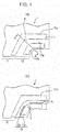
- the method is a method of manufacturing a curved channel part by press forming by using a blank 1, the blank 1 including a base section 11 that is not deformed and a deformation section 12 that is deformed by press forming, the blank 1 including a portion 12a to be a vertical wall portion in the deformation section 12, the curved channel part having a curved portion in the vertical wall portion.
- the method includes a shear deformation step of individually restraining a boundary-side portion 11a of the base section 11 with respect to the deformation section 12 and an outer portion 12b of the deformation section 12, shear-deforming the portion 12a to be the vertical wall portion of the deformation section 12 in a sheet face, and as shown in Fig. 1(b) , causing a material to flow (movement of the material in the blank) from a portion separated from the curved portion toward the curved portion in an outer edge portion of the portion 12a to be the vertical wall portion.
- the outer portion 12b is a portion to be a flange portion if a curved channel part with a flange portion is manufactured, and is a portion to be transiently a flange portion if a curved channel part without a flange portion is manufactured.
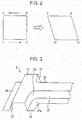
- shear deformation is deformation in which a rectangle ABCD is deformed into a parallelogram ABC1D1 when parallel forces in opposite directions (shear forces) are applied in an AB direction and a DC direction.
- the material flows as indicated by arrow X (from the portion separated from the curved portion toward the curved portion) in the outer edge portion of the portion 12a to be the vertical wall portion. Accordingly, stretch flange deformation hardly occurs in the outer edge portion of the curved portion.
- the shear deformation step since the outer portion 12b and the boundary-side portion 11a are restrained, the material cannot be moved, and the portion 12a to be the vertical wall portion is shear-deformed in the sheet face. Accordingly, the shear deformation step can be stably executed even if the surface roughness and clearance of a die; the cushion force; the intensity, stretch, and thickness of a blank; etc., vary during volume production.
- the second restraining section in the step of forming the vertical wall portion, when viewed in a thickness direction of the flat-sheet-shaped processing material, from a state in which a second restraining section that restrains the outer portion of the deformation section is separated from a first restraining section that restrains the boundary-side portion, the second restraining section may be relatively moved in a direction in which a separation distance between the first restraining section and the second restraining section decreases as the boundary portion is bent.
- the shear deformation step can be executed by a method of the following configuration (3) or (4).
- the cross-sectional shape and dimension of the portion to be the vertical wall are hardly changed in a portion other than a portion which is changed to the bent portion (boundary portions of the vertical wall portion with respect to the top portion and the flange portion). Accordingly, a stretch or a wrinkle is hardly generated in the vertical wall portion.
- the cross-sectional shape and dimension of the portion 12a to be the vertical wall portion are changed.
- the angle in the range from 30° to 60°, a stretch which occurs in the vertical wall portion is not so large that the stretch causes a crack to be generated.
- a wrinkle generated in the vertical wall portion can be brought into a removable state in post-processing.
- the angle is smaller than 30°, when the vertical wall portion is formed only in the shear deformation step, the corrected degree of deformation of the portion to be the vertical wall portion (the state in which the material is excessive and bent) is insufficient, and a wrinkle generated in the vertical wall portion may not be removed by post-processing. If the angle exceeds 60°, the material of the portion to be the vertical wall portion is largely stretched (the direction of this stretch differs from the direction of the shear deformation), and a crack may be generated due to insufficiency in ductility of the material.
- the press forming method of this aspect may be executed in combination with the shear deformation step, a deep drawing step of related art, and a stamping step of related art like the configurations (5) to (7).
- the outer portion 12b of the deformation section is present in a flange shape at the outside of the vertical wall portion. Accordingly, if a curved channel part without a flange portion is manufactured by the press forming method of this aspect, at the outside of the vertical wall portion, post-processing is required.
- the post-processing may be a method of removing the flange-shaped outer portion 12b by using laser cutting and a trim die.
- the stamping step being a press forming method of related art is executed.
- the configuration (7) as compared with a case in which the vertical wall portion is formed only in the stamping step, stretch flange deformation of the curved channel part is reduced. Also, even in a method executing post-processing of removing the flange-shaped outer portion 12b after the shear deformation step is executed, as compared with the case in which the vertical wall portion is formed only in the stamping step, stretch flange deformation of the curved channel part is reduced.
- the press forming method of this aspect may include the following configuration (8) or (9).
- the press forming method includes a wrinkle stretching step of stretching a wrinkle, which is generated in the vertical wall portion, by pinching the vertical wall portion with a die after the shear deformation step.
- the material of the blank is softened in the shear deformation step. Accordingly, shear deformation likely occurs in the portion to be the vertical wall portion, and even if a wrinkle is generated in the portion to be the vertical wall portion, the wrinkle is likely stretched.
- the heating position of the blank may be the portion to be the vertical wall portion, or the blank may be entirely heated. Even if the blank is entirely heated, the material of the portion to be restrained is cooled by the die and is hardened. Accordingly, the entirely heated blank does not affect the restraint.
- the method of heating the blank may be a typical heating method, such as heating in a heating furnace, high-frequency heating, or electrical heating.
- the material of the blank to be used in the press forming method of this aspect may be any of materials of blanks used in press forming methods of related art.
- a blank with difficulty in press forming by the methods of related art such as a steel sheet with a high strength of 590 MPa or higher or an aluminum alloy sheet
- the press forming method of this aspect by executing the press forming method of this aspect, the curved channel part in which stretch flange deformation and generation of a wrinkle are restricted can be obtained.
- the base section and the outer portion of the deformation section of the blank are individually restrained in the shear deformation step.
- the restraining method may employ a known method of related art. For example, there may be a method of fixing a blank by pinching the blank with a jig, a method of providing a protrusion on a die and hooking a blank to the protrusion, and a method of fixing a blank with a magnetic force. One of these methods may be employed or these methods may be combined and employed.
- a method of providing a screw such as a bolt in the jig that pinches the blank there may be a method of providing a screw such as a bolt in the jig that pinches the blank.
- a force for fastening the blank with the jig may be applied by a fastening force of the screw.
- a bead portion may be provided in the jig that pinches the blank.
- bending/unbending deformation and frictional resistance which are received by the material when the material moves through the bead portion may be used as a restraining force against the movement of the material.
- There may be also a method of making a protruding and depressed shape by knurling in the jig that pinches and fixes the blank There may be also a method of making a protruding and depressed shape by knurling in the jig that pinches and fixes the blank.
- the method of knurling processing may be a method of cutting, and transferring the protruding and depressed shape by strongly pressing the shape to the jig.
- any method may be employed as long as the protruding and depressed shape is provided in the jig.
- the hardening method may be a method of applying hardening processing, such as high-frequency hardening, carburizing, flame hardening, or laser hardening; or a surface modifying method, such as low-temperature sulfurizing processing, a chemical vapor deposition method, or a physical vapor deposition method.
- hardening processing such as high-frequency hardening, carburizing, flame hardening, or laser hardening
- surface modifying method such as low-temperature sulfurizing processing, a chemical vapor deposition method, or a physical vapor deposition method.
- the moving method while the outer portion of the blank is restrained may be a method of using a motion of slide of a press machine which is used by a typical press forming method, by converting the motion in the up-down direction into a motion made with the configuration (3) or (4).
- a mechanism using an inclined surface represented by a cam mechanism, a link mechanism, or a mechanism using a lever may be employed.
- a method using a cylinder utilizing electricity, an air pressure, or a hydraulic pressure may be employed.
- the shear deformation step can be stably executed even if various variations are made during volume production. Accordingly, the shear deformation step can make significant contribution to decrease in defective rating of pressed products.
- the present invention can make significant contribution to decrease in weight and increase in strength of parts.
- a curved channel part is described as an example of a press-formed part being a subject to be manufactured.
- the present invention is not limited to the curved channel part. Any part may be a subject of the present invention as long as the part is a press-formed part having a vertical wall portion having a curved portion that is curved in a depressed shape toward a top portion during forming. Fig.
- 3 provides an example of a shape, in which a boundary portion between a top portion and a vertical wall portion is bent at a curved bending line to form a curved portion so that a vertical wall portion 22 is depressed toward a top portion 21, that is the vertical wall portion 22 is deformed by off-plane deformation (curved) in a direction in which the vertical wall portion 22 is drawn toward the top portion 21.
- the curved channel part shown in Fig. 3 is manufactured.
- Such a curved channel part is used as, for example, a center pillar part of a vehicle.
- a curved channel part 2 includes a top portion 21 corresponding to a base section, a vertical wall portion 22 with a curved portion 22a, a vertical wall portion 23 without a curved portion, a flange portion 24 continuous to the vertical wall portion 22 with the curved portion 22a, and a flange portion 25 continuous to the vertical wall portion 23 without a curved portion.
- the flange portion 24 has a curved portion 24a in a portion continuous to the curved portion 22a of the vertical wall portion 22.
- the vertical wall portion 22 with the curved portion 22a and the flange portion 24 continuous to the vertical wall portion 22 of the curved channel part 2 are formed by the following method.
- a portion other than the curved portion 22a may be formed in a typical deep drawing step.
- the vertical wall portion 23 without a curved portion and the flange portion 25 continuous to the vertical wall portion 23 are formed in the typical deep drawing step.
- a die used for press forming includes a punch 31 arranged below a blank 1 configuring a flat-sheet-shaped processing material, a first pad 32 arranged above the punch 31 with the blank 1 interposed therebetween, a blank holder 33 arranged at a lateral side of the punch 31 with a distance S0 interposed therebetween, and a second pad 34 arranged above the blank holder 33 with the blank 1 interposed therebetween.
- the installation distance S0 between the punch 31 and the second pad 34 is the same as the height of the vertical wall portion 22 of the curved channel part 2 to be manufactured.
- the blank 1 is a uniform single sheet. As shown in Fig. 4 , for convenience of description, if it is considered that the blank 1 is separated into a base section 11 which is not deformed and a deformation section 12 which is deformed by press forming, the deformation section 12 includes a portion 12a to be the vertical wall portion 22. Also, in this embodiment, since the curved channel part 2 having the flange portion 24 is manufactured, the deformation section 12 includes a portion to be the flange portion 24.
- a boundary-side portion (a portion of the base section 11 at the boundary side with respect to the deformation section 12) 11a of the base section 11 of the blank 1 is pinched and restrained by the punch 31 and the first pad 32, and an outer portion (the portion to be the flange portion) 12b of the deformation section 12 is pinched and restrained by the blank holder 33 and the second pad 34.
- a center portion 11b of the base section 11 may be restrained or may not be restrained.
- the punch 31 and the first pad 32 configure a first restraining section
- the blank holder 33 and the second pad 34 configure a second restraining section
- the blank holder 33 and the second pad 34 that restrain the outer portion 12b are moved along arrow A to approach the punch 31 and the first pad 32 while being turned relatively downward so that the portion 12a to be the vertical wall portion is rotated around a point (a bending point of the curved portion 22a of the vertical wall portion 22) B on the boundary line with respect to the boundary-side portion 11a as indicated by arrow A.
- This corresponds to a shear deformation step.
- the portion 12a to be the vertical wall portion of the blank 1 is bent at the boundary between the boundary-side portion 11a and the outer portion 12b, and becomes the vertical wall portion 22 of the curved channel part 2.
- the cross-sectional shape or the dimension of the portion 12a to be the vertical wall portion of the blank 1 is not changed in a portion other than the bent portion. Accordingly, a wrinkle is hardly generated in the vertical wall portion 22 of the curved channel part 2.
- the curved channel part 2 having the shape shown in Fig. 3 is manufactured.
- the vertical wall portion 22 with the curved portion 22a and the flange portion 24 continuous to the vertical wall portion 22 of the curved channel part 2 are formed by the following method shown in Fig. 6 .
- the method in this embodiment differs from the method in the first embodiment in the moving method of the blank holder 33 and the second pad 34 that restrain the outer portion 12b, and is similar to the method in the first embodiment for the other points.
- the boundary-side portion 11a of the base section 11 of the blank 1 is pinched and restrained by the punch 31 and the first pad 32, and the outer portion (the portion to be the flange portion) 12b of the deformation section 12 is pinched and restrained by the blank holder 33 and the second pad 34.
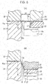
- the blank holder 33 and the second pad 34 that restrain the outer portion 12b are linearly moved obliquely downward to approach the punch 31 and the first pad 32 when viewed in the thickness direction of the blank as indicated by arrow C in Fig. 6 .
- the blank holder 33 and the second pad 34 are linearly moved in an oblique direction in which an angle ( ⁇ ) with respect to the sheet face of the blank 1 is in a range from 30° to 60°.
- shear deformation occurs in the sheet face of the portion 12a to be the vertical wall portion of the deformation section 12 by the movement of the outer portion 12b indicated by arrow Y, and the material flows in the direction indicated by arrow X in the outer edge portion of the portion 12a to be the vertical wall portion.
- the shear deformation direction is a direction perpendicular to the paper face.
- stretch flange deformation hardly occurs in the outer edge portion of the curved portion 22a of the vertical wall portion 22.
- ⁇ is in the range from 30° to 60°, a crack caused by a stretch generated in the vertical wall portion 22 can be avoided, and a wrinkle generated in the vertical wall portion 22 can be removed by post-processing etc.
- a wrinkle generated in the portion 12a to be the vertical wall portion in the state in Fig. 6 can be stretched by pinching the wrinkle by the side surface of the punch 31 and the side surface of the second pad 34.
- the curved channel part 2 having the shape shown in Fig. 3 is manufactured.
- the vertical wall portion 22 with the curved portion 22a and the flange portion 24 continuous to the vertical wall portion 22 of the curved channel part 2 are formed by the following method shown in Fig. 7 .
- a die to be used for press forming is similar to that in Fig. 4 ; however, as shown in Fig. 7 , a punch 35 having a protruding portion 35a at a side surface (a pressing surface that contacts the vertical wall portion) is arranged below the blank 1.
- a second pad 36 having a depressed portion 36a at a side surface is arranged above the blank holder 33. The other points are similar to the second embodiment.
- the blank holder 33 and the second pad 36 that restrain the outer portion 12b are linearly moved obliquely downward in which the angle ( ⁇ ) with respect to the sheet face of the blank 1 is in the range from 30° to 60° as indicated by arrow C.
- the linear movement shear deformation occurs in the sheet face of the portion 12a to be the vertical wall portion of the blank 1, and as indicated by a two-dot chain line in Fig. 7 , the cross-sectional shape of the portion 12a to be the vertical wall portion of the blank 1 is changed. Meanwhile, a portion, which is near the boundary with respect to the outer portion 12b, of the portion 12a to be the vertical wall portion is moved along arrow A in Fig. 7 while being bent.
- a portion 12f of the portion 12a to be the vertical wall portion is pinched by the protruding portion 35a of the punch 35 and the depressed portion 36a of the second pad 36, and becomes a surface substantially perpendicular to a surface of the flange portion 24.
- This step is a wrinkle stretching step.
- the wrinkle is likely stretched.
- the line length of the portion 12a to be the vertical wall portion is elongated by the amount corresponding to the depressed portion 36a, that is, the line length can be increased. As the result, even if a wrinkle is generated in the vertical wall portion, the wrinkle can be stretched.
- the wrinkle stretching step may be executed at last after the shear deformation step described in the first embodiment etc. Since the wrinkle stretching step is executed continuously to the shear deformation step, the number of steps can be prevented from being increased for the wrinkle stretching step.
- the curved channel part 2 having the shape shown in Fig. 3 is manufactured.
- the vertical wall portion 22 with the curved portion 22a and the flange portion 24 continuous to the vertical wall portion 22 of the curved channel part 2 are formed by the following method shown in Fig. 8 .
- the vertical wall portion 22 is formed by two steps including the shear deformation step and then a deep drawing step.
- the outer portion 12b that is restrained in the shear deformation step includes a portion of the portion to be the vertical wall portion 22.
- an inner portion (a portion near the base section 11) 12c being a portion to be the vertical wall portion 22 is shear-deformed in the sheet face.
- a die used in the shear deformation step is basically the same as that of the second embodiment.
- the installation distance S0 between the punch 31 and the second pad 34 is a value corresponding to a half of a height T2 (see Fig. 8(b) ) of the vertical wall portion 22 of the curved channel part 2 to be manufactured or a value obtained by adding or subtracting a previously set margin amount to and from the half of the height T2.
- the boundary-side portion 11a of the base section 11 of the blank 1 is pinched and restrained by the punch 31 and the first pad 32, and the outer portion (the portion of the portion to be the vertical wall portion 22 and the portion to be the flange portion 24) 12b of the deformation section 12 is pinched and restrained by the blank holder 33 and the second pad 34.
- This shear deformation step is executed until a timing before the angle between the boundary-side portion 11a of the base section 11 and the inner portion 12c of the deformation section 12 reaches an angle of a final product.
- a die 37 is arranged instead of the second pad 34 that restrains the outer portion 12b, the die 37 and the blank holder 33 are moved along arrow B, and thus the deep drawing step is executed. Accordingly, the outer portion 12b is stretched while being drawn toward the punch 31, and the inner portion 12c is also drawn and stretched. Thus, the vertical wall portion 22 is formed.
- the curved channel part 2 having the shape shown in Fig. 3 is manufactured.
- the vertical wall portion 22 with the curved portion 22a and the flange portion 24 continuous to the vertical wall portion 22 of the curved channel part 2 are formed by the following method shown in Fig. 9 .
- the vertical wall portion 22 is formed by two steps including the deep drawing step and then the shear deformation step.
- the boundary-side portion 11a of the base section 11 of the blank 1 is pinched and restrained by the punch 31 and the first pad 32, and an outer portion 12d of the deformation section 12 (the portion of the portion 12a to be the vertical wall portion 22 and the portion to be the flange portion 24) is pinched by the die 37 and the blank holder 33.
- the inner portion 12c of the deformation section 12 of the blank 1 is present while not being restrained.
- the deep drawing step is executed by moving the die 37 and the blank holder 33 along arrow B while a predetermined tensile force is applied to the outer portion 12d.
- the outer portion 12d is bent while being drawn and stretched toward the punch 31, and the blank 1 obtains a shape having a bent portion between the portion 12a to be the vertical wall portion and the outer portion 12b.
- the deep drawing step is executed until an angle ⁇ between the portion 12a to be the vertical wall portion and a side surface of the die 37 becomes, for example, in a range from 45° to 60°.
- shear deformation occurs in the sheet face of the portion 12a to be the vertical wall portion of the blank 1, and the vertical wall portion 22 and the flange portion 24 are formed. This corresponds to the shear deformation step.
- a curved channel part shown in Fig. 10 is manufactured.
- Such a curved channel part is used as, for example, a lower arm part of a vehicle.
- a curved channel part 4 includes a top portion 41, and a vertical wall portion 42 with a curved portion 42a.
- the vertical wall portion 42 is formed by two steps including a shear deformation step and a stamping step.
- the basic configuration of a die used in the shear deformation step is the same as the second embodiment.
- the boundary-side portion 11a of the base section 11 of the blank 1 is pinched and restrained by the punch 31 and the first pad 32, and the outer portion (the portion to be transiently the flange portion) 12b of the deformation section 12 is pinched and restrained by the blank holder 33 and the second pad 34.
- the punch 31 and the first pad 32, and the blank holder 33 and the second pad 34 are separated by the separation distance S0 when viewed in the thickness direction of the blank 1.
- the blank holder 33 and the second pad 34 restraining the outer portion 12b are moved so that the portion 12a to be the vertical wall portion is rotated around the boundary point B with respect to the boundary-side portion 11a as indicated by arrow A.
- the second pad 34 and the blank holder 33 restraining the outer portion 12b are released, and the die 37 is arranged on the portion 12a to be the vertical wall portion and the outer portion 12b. Then, by moving the die 37 along arrow B, the bent portion is stretched and hence the vertical wall portion 42 is formed. This corresponds to the stamping step.
- shear deformation step that is executed before the stamping step may be executed by linearly moving the restrained outer portion 12b in the direction in which the angle ( ⁇ ) with respect to the sheet face of the blank 1 is in the range from 30° to 60° as indicated by arrow C in Fig. 11(a) .
- the curved channel part shown in Fig. 10 may be manufactured by a method of cutting the flange portion 24 after a flanged formed part is once obtained by the method of the first embodiment or the second embodiment.
- Fig. 12 shows another embodiment of a curved channel part being a subject of the present invention.
- this curved channel part 60 is an example in which a curved portion is formed so that a vertical wall portion 62 is depressed toward a top portion 61, that is, by deforming the vertical wall portion 62 by in-plane deformation (curving the vertical wall portion 62) in a height direction so that the vertical wall portion 62 is depressed toward the top portion 61, when the boundary portion between the top portion 61 and the vertical wall portion 62 is bent at a curved bending line.
- the top portion 61 also obtains a curved shape to be depressed toward the vertical wall portion.
- top portion 61 is also curved, facing surfaces of the punch 31 and the first pad 32 for holding the blank have surface shapes along the curved top portion.
- the curved portion may be a subject of the present invention.
- the vertical wall portion 22 and the flange portion 24 continuous to the vertical wall portion 22 of the curved channel part 2 shown in Fig. 3 were formed. Also, by the method described in the sixth embodiment and a press forming method of related art (stamping), the curved channel part 4 shown in Fig. 10 was formed.
- a material located at the flange portion is drawn into the vertical wall portion, and hence the shape of the flange portion after forming is different from the method of any of the first to fifth embodiments.
- the shapes of the blanks were changed between the methods according to the first to fifth embodiments and the deep drawing, so that the flange width near the curved portion of the vertical wall portion was 50 mm after press forming.
- the shape of the blank for deep drawing was obtained by inverse analysis based on the total strain theory.
- a blank was heated by using a heating furnace, and the temperature of the blank before forming was measured by using an infrared radiation thermometer.
- the vertical wall portion 22 and the flange portion 24 continuous to the vertical wall portion 22 of the curved channel part 2 shown in Fig. 3 were formed only in the shear deformation step by the method of the first embodiment shown in Fig. 5 .
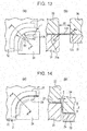
- Fig. 13(a) is a plan view of the used die and blank.
- Fig. 13(b) is an A-A cross-sectional view thereof.
- the arrangement distance S0 between the punch 31 and the second pad 34 shown in Fig. 13(b) was set at 100 mm.
- a chamfering radius R3 of an upper-end corner portion of the punch 31 was set at 10 mm
- a chamfering radius R4 of a lower-end corner portion of the second pad 34 was set at 10 mm.
- the boundary-side portion 11a of the base section 11 of the blank 1 was pinched and restrained by the punch 31 and the first pad 32, and the outer portion (the portion to be the flange portion) 12b of the deformation section 12 was pinched and restrained by the blank holder 33 and the second pad 34.
- Fig. 14(a) is a plan view of the die and blank in this state.
- Fig. 14(b) is an A-A cross-sectional view thereof.
- a height T of the vertical wall portion 22 in Fig. 14(b) was 100 mm.
- the shear deformation step was executed at a room temperature by using a non-heated blank.
- the crack was O (no crack), and the wrinkle was ⁇ (very small wrinkle negligible in quality).
- the vertical wall portion 22 and the flange portion 24 continuous to the vertical wall portion 22 of the curved channel part 2 shown in Fig. 3 were manufactured by the same method as the sample No. 1-1 except the following point.
- a wrinkle stretching step was executed by further pinching the vertical wall portion 22 by the punch 31 and the second pad 34.
- the vertical wall portion 22 and the flange portion 24 continuous to the vertical wall portion 22 of the curved channel part 2 shown in Fig. 3 were manufactured by the same method as the sample No. 1-1 except the following point.
- the shear deformation step was executed by using a blank heated at 300°C.
- the vertical wall portion 22 and the flange portion 24 continuous to the vertical wall portion 22 of the curved channel part 2 shown in Fig. 3 were manufactured by the same method as the sample No. 1-1 except the following point.
- the shear deformation step was executed by using a blank heated at 300°C. Also, from the state in Fig. 14(b) , the wrinkle stretching step was executed by further pinching the vertical wall portion 22 by the punch 31 and the second pad 34.
- the vertical wall portion 22 and the flange portion 24 continuous to the vertical wall portion 22 of the curved channel part 2 shown in Fig. 3 were formed only in the shear deformation step by the method of the second embodiment shown in Fig. 6 .
- the boundary-side portion 11a of the base section 11 of the blank 1 was pinched and restrained by the punch 31 and the first pad 32, and the outer portion (the portion to be the flange portion) 12b of the deformation section 12 was pinched and restrained by the blank holder 33 and the second pad 34.
- Fig. 14(a) is the plan view of the die and blank in this state.
- Fig. 14(b) is the A-A cross-sectional view thereof.
- the height T of the vertical wall portion 22 in Fig. 14(b) was 100 mm.
- the shear deformation step was executed at a room temperature by using a non-heated blank.
- the vertical wall portion 22 and the flange portion 24 continuous to the vertical wall portion 22 of the curved channel part 2 shown in Fig. 3 were manufactured by the same method as the sample No. 2-1 except the following point.
- the wrinkle stretching step was executed by further pinching the vertical wall portion 22 by the punch 31 and the second pad 34.
- the vertical wall portion 22 and the flange portion 24 continuous to the vertical wall portion 22 of the curved channel part 2 shown in Fig. 3 were manufactured by the same method as the sample No. 2-1 except the following point.
- the shear deformation step was executed by using a blank heated at 300°C.
- the vertical wall portion 22 and the flange portion 24 continuous to the vertical wall portion 22 of the curved channel part 2 shown in Fig. 3 were manufactured by the same method as the sample No. 2-1 except the following point.
- the shear deformation step was executed by using a blank heated at 300°C. Also, from the state in Fig. 14(b) , the wrinkle stretching step was executed by further pinching the vertical wall portion 22 by the punch 31 and the second pad 34.
- the vertical wall portion 22 and the flange portion 24 continuous to the vertical wall portion 22 of the curved channel part 2 shown in Fig. 3 were manufactured by the same method as the sample No. 2-1 except the following point.
- the angle ( ⁇ ) at which the blank holder 33 and the second pad 34 were linearly moved along arrow C was set at 45°.
- a generated crack and a generated wrinkle were evaluated on the basis of Tables 2 and 3.
- the crack was ⁇ (no crack), and the wrinkle was O (very small wrinkle negligible in quality).
- the vertical wall portion 22 and the flange portion 24 continuous to the vertical wall portion 22 of the curved channel part 2 shown in Fig. 3 were manufactured by the same method as the sample No. 2-2 except the following point.
- the angle ( ⁇ ) at which the blank holder 33 and the second pad 34 were linearly moved along arrow C was set at 45°.
- the vertical wall portion 22 and the flange portion 24 continuous to the vertical wall portion 22 of the curved channel part 2 shown in Fig. 3 were manufactured by the same method as the sample No. 2-3 except the following point.
- the angle ( ⁇ ) at which the blank holder 33 and the second pad 34 were linearly moved along arrow C was set at 45°.
- the vertical wall portion 22 and the flange portion 24 continuous to the vertical wall portion 22 of the curved channel part 2 shown in Fig. 3 were manufactured by the same method as the sample No. 2-4 except the following point.
- the angle ( ⁇ ) at which the blank holder 33 and the second pad 34 were linearly moved along arrow C was set at 45°.
- the vertical wall portion 22 and the flange portion 24 continuous to the vertical wall portion 22 of the curved channel part 2 shown in Fig. 3 were manufactured by the same method as the sample No. 2-1 except the following point.
- the angle ( ⁇ ) at which the blank holder 33 and the second pad 34 were linearly moved along arrow C was set at 60°.
- a generated crack and a generated wrinkle were evaluated on the basis of Tables 2 and 3.
- the crack was ⁇ (no crack), and the wrinkle was ⁇ (very small wrinkle negligible in quality).
- the vertical wall portion 22 and the flange portion 24 continuous to the vertical wall portion 22 of the curved channel part 2 shown in Fig. 3 were manufactured by the same method as the sample No. 2-2 except the following point.
- the angle ( ⁇ ) at which the blank holder 33 and the second pad 34 were linearly moved along arrow C was set at 60°.
- the vertical wall portion 22 and the flange portion 24 continuous to the vertical wall portion 22 of the curved channel part 2 shown in Fig. 3 were manufactured by the same method as the sample No. 2-3 except the following point.
- the angle ( ⁇ ) at which the blank holder 33 and the second pad 34 were linearly moved along arrow C was set at 60°.
- the vertical wall portion 22 and the flange portion 24 continuous to the vertical wall portion 22 of the curved channel part 2 shown in Fig. 3 were manufactured by the same method as the sample No. 2-4 except the following point.
- the angle ( ⁇ ) at which the blank holder 33 and the second pad 34 were linearly moved along arrow C was set at 60°.
- the vertical wall portion 22 and the flange portion 24 continuous to the vertical wall portion 22 of the curved channel part 2 shown in Fig. 3 were manufactured by the same method as the sample No. 2-1 except the following point.
- the angle ( ⁇ ) at which the blank holder 33 and the second pad 34 were linearly moved along arrow C was set at 20°.
- the vertical wall portion 22 and the flange portion 24 continuous to the vertical wall portion 22 of the curved channel part 2 shown in Fig. 3 were manufactured by the same method as the sample No. 2-2 except the following point.
- the angle ( ⁇ ) at which the blank holder 33 and the second pad 34 were linearly moved along arrow C was set at 20°.
- the vertical wall portion 22 and the flange portion 24 continuous to the vertical wall portion 22 of the curved channel part 2 shown in Fig. 3 were manufactured by the same method as the sample No. 2-3 except the following point.
- the angle ( ⁇ ) at which the blank holder 33 and the second pad 34 were linearly moved along arrow C was set at 20°.
- the vertical wall portion 22 and the flange portion 24 continuous to the vertical wall portion 22 of the curved channel part 2 shown in Fig. 3 were manufactured by the same method as the sample No. 2-4 except the following point.
- the angle ( ⁇ ) at which the blank holder 33 and the second pad 34 were linearly moved along arrow C was set at 20°.
- the vertical wall portion 22 and the flange portion 24 continuous to the vertical wall portion 22 of the curved channel part 2 shown in Fig. 3 were manufactured by the same method as the sample No. 2-1 except the following point.
- the angle ( ⁇ ) at which the blank holder 33 and the second pad 34 were linearly moved along arrow C was set at 70°.
- the vertical wall portion 22 and the flange portion 24 continuous to the vertical wall portion 22 of the curved channel part 2 shown in Fig. 3 were manufactured by the same method as the sample No. 2-2 except the following point.
- the angle ( ⁇ ) at which the blank holder 33 and the second pad 34 were linearly moved along arrow C was set at 70°.
- the vertical wall portion 22 and the flange portion 24 continuous to the vertical wall portion 22 of the curved channel part 2 shown in Fig. 3 were manufactured by the same method as the sample No. 2-3 except the following point.
- the angle ( ⁇ ) at which the blank holder 33 and the second pad 34 were linearly moved along arrow C was set at 70°.
- the vertical wall portion 22 and the flange portion 24 continuous to the vertical wall portion 22 of the curved channel part 2 shown in Fig. 3 were manufactured by the same method as the sample No. 2-4 except the following point.
- the angle ( ⁇ ) at which the blank holder 33 and the second pad 34 were linearly moved along arrow C was set at 70°.
- the vertical wall portion 22 and the flange portion 24 continuous to the vertical wall portion 22 of the curved channel part 2 shown in Fig. 3 were formed in two steps of the deep drawing step and then the shear deformation step by the method of the fifth embodiment shown in Fig. 9 .
- the die used in the deep drawing step is provided by replacing the second pad 34 with the die 37 in the die shown in Fig. 13 .
- the chamfering radius at a lower-end corner portion of the die 37 is 10 mm being the same as the chamfering radius R4 of a lower-end corner portion of the second pad 34 of the die shown in Fig. 13 .
- a distance L (see Fig. 9(a) ) between the punch 31 and the die 37 was set at 87 mm.
- the boundary-side portion 11a of the base section 11 of the blank 1 was pinched and restrained by the punch 31 and the first pad 32, and the outer portion 12d of the deformation section 12 of the blank 1 was arranged between the blank holder 33 and the die 37.
- the deep drawing step was executed, in which the blank holder 33 and the die 37 were moved in the B direction by 50 mm while a tensile force was applied to the outer portion 12d.
- the deep drawing step was executed until the angle ⁇ between the portion 12a to be the vertical wall portion and the side surface of the die 37 became 60°. Accordingly, the height T1 of the portion 12a to be the vertical wall portion was set at 50 mm.
- the die 37 was replaced with the second pad 34, the blank holder 33 and the second pad 34 were connected to the same moving mechanism as that used for the sample No. 2-1, and as shown in Fig. 9(b) , the outer portion 12d of the deformation section 12 of the blank 1 was restrained between the blank holder 33 and the second pad 34.
- the arrangement distance S0 between the punch 31 and the second pad 34 was set at 87 mm.
- the angle ⁇ with respective to the sheet face of the portion 12a to be the vertical wall portion of the blank 1 was set at 60°, and the blank holder 33 and the second pad 34 were linearly moved along arrow C. The movement was executed until a distance S between the punch 31 and the second pad 34 became 10 mm. Accordingly, the portion 12a to be the vertical wall portion was shear-deformed and the vertical wall portion 22 was formed. A height T2 of the vertical wall portion 22 in Fig. 9(b) was 100 mm.
- the shear deformation step was executed at a room temperature by using a non-heated blank.
- the vertical wall portion 22 and the flange portion 24 continuous to the vertical wall portion 22 of the curved channel part 2 shown in Fig. 3 were manufactured by the same method as the sample No. 7-1 except the following point.
- the wrinkle stretching step was executed by further pinching the vertical wall portion 22 by the punch 31 and the second pad 34.
- the vertical wall portion 22 and the flange portion 24 continuous to the vertical wall portion 22 of the curved channel part 2 shown in Fig. 3 were manufactured by the same method as the sample No. 7-1 except the following point.
- the shear deformation step was executed by using a blank heated at 300°C.
- the vertical wall portion 22 and the flange portion 24 continuous to the vertical wall portion 22 of the curved channel part 2 shown in Fig. 3 were manufactured by the same method as the sample No. 7-1 except the following point.
- the shear deformation step was executed by using a blank heated at 300°C. Also, from the state in Fig. 9(b) , the wrinkle stretching step was executed by further pinching the vertical wall portion 22 by the punch 31 and the second pad 34.
- the vertical wall portion 22 and the flange portion 24 continuous to the vertical wall portion 22 of the curved channel part 2 shown in Fig. 3 were formed in two steps of the shear deformation step and then the deep drawing step by the method of the fourth embodiment shown in Fig. 8 .
- the same die as that used for the sample No. 2-1 was used, and the arrangement distance S0 (see Fig. 8(a) ) between the punch 31 and the second pad 34 was set at 50 mm.
- the boundary-side portion 11a of the base section 11 of the blank 1 was pinched and restrained by the punch 31 and the first pad 32, and the outer portion (the portion to be the flange portion) 12b of the deformation section 12 was pinched and restrained by the blank holder 33 and the second pad 34.
- the shear deformation step was executed at a room temperature by using a non-heated blank until a height T1 of the inner portion 12c of the blank 1 became 50 mm.
- the second pad 34 was replaced with the die 37, the die 37 and the blank holder 33 were connected to the moving mechanism for deep drawing, and the outer portion 12b of the blank 1 was arranged between the die 37 and the blank holder 33.
- the deep drawing step was executed, in which the die 37 and the blank holder 33 were moved in the B direction by 50 mm while a tensile force was applied to the outer portion 12b.
- the deep drawing step was executed until the height T2 of the vertical wall portion 22 became 100 mm.
- the vertical wall portion 22 and the flange portion 24 continuous to the vertical wall portion 22 of the curved channel part 2 shown in Fig. 3 were manufactured by the same method as the sample No. 8-1 except the following point.
- the wrinkle stretching step was executed by further pinching the vertical wall portion 22 by the punch 31 and the die 37.
- the vertical wall portion 22 and the flange portion 24 continuous to the vertical wall portion 22 of the curved channel part 2 shown in Fig. 3 were manufactured by the same method as the sample No. 8-1 except the following point.
- the shear deformation step was executed by using a blank heated at 300°C.
- the vertical wall portion 22 and the flange portion 24 continuous to the vertical wall portion 22 of the curved channel part 2 shown in Fig. 3 were manufactured by the same method as the sample No. 8-1 except the following point.
- the shear deformation step was executed by using a blank heated at 300°C. Also, from the state in Fig. 8(b) , the wrinkle stretching step was executed by further pinching the vertical wall portion 22 by the punch 31 and the die 37.
- the vertical wall portion 22 and the flange portion 24 continuous to the vertical wall portion 22 of the curved channel part 2 shown in Fig. 3 were formed only in the deep drawing step.
- Fig. 15(a) is a plan view of the used die and blank.
- Fig. 15(b) is an A-A cross-sectional view thereof.
- the die used for press forming is the same as the die for deep drawing of related art, and includes a die 51, a punch 52, and a pair of blank holders 53.
- a depth F of the depressed portion of the die 51 is 100 mm.
- a portion of an outer peripheral surface 52a of the punch 52, which corresponds to the curved portion 22a, has a curvature radius R2 of 90 mm.
- a distance K between the inner peripheral surface 51a of the die 51 and the outer peripheral surface 52a of the punch 52 was set at 10 mm.
- a chamfering radius R3 of an upper-end corner portion of the punch 52 was set at 10 mm, and a chamfering radius R4 of a lower-end corner portion of the inner peripheral surface 51a of the die 51 was set at 10 mm.
- the blank holders 53 were arranged at both sides of the punch 52, and the blank 1 was arranged on the punch 52 and the blank holders 53.
- the base section 11 of the blank 1 was arranged on the punch 52, and the deformation section 12 was arranged on the blank holders 53.
- the die 51 was arranged above the blank 1, and the die 51 was lowered.
- a proper tensile force was applied to the deformation section 12 of the blank 1 held by a protruding portion 51b of the die 51 and the blank holders 53.
- the deep drawing step was executed at a room temperature.
- the deformation section 12 of the blank 1 is moved toward the punch 52 between the protruding portion 51b of the die 51 and the blank holders 53 as indicated by arrow B while the deformation section 12 is bent by a depressed portion of the die 51 and the punch 52, and the material largely drawn into the area between the punch 52 and the die 51 forms the vertical wall portion 22.
- the curved channel part 2 including the vertical wall portion 22 with a height T of 100 mm was obtained.
- a generated crack and a generated wrinkle were evaluated on the basis of Tables 2 and 3. As the result, if the material of the used blank was "270,” the crack was ⁇ , and otherwise, the crack was ⁇ (F). If the material of the used blank was any of "270" and “aluminum alloy,” the wrinkle was ⁇ (very small wrinkle negligible in quality), and otherwise, the wrinkle was ⁇ (noticeable wrinkle).
- the wrinkle evaluation had no problem; however, necking occurred at an end portion of the vertical wall portion. If any of 590, 980, 1180 MPa grade steel sheets with high strengths was used as the blank, a noticeable wrinkle was generated in the vertical wall portion, and a crack was generated in the flange portion. If an aluminum alloy sheet was used as the blank, the wrinkle evaluation had no problem; however, a crack was generated in the flange portion.
- the vertical wall portion 22 and the flange portion 24 continuous to the vertical wall portion 22 of the curved channel part 2 shown in Fig. 3 were manufactured by the same method as the sample No. 9-1 except the following point.
- the deep drawing step was executed by using a blank heated at 300°C.
- a generated crack and a generated wrinkle were evaluated on the basis of Tables 2 and 3.
- the crack was ⁇ (crack in vertical wall portion). If the material of the used blank was any of "980" and "1180,” the wrinkle was ⁇ (noticeable wrinkle), and otherwise, the wrinkle was ⁇ (very small wrinkle negligible in quality).
- the curved channel part 4 shown in Fig. 10 was formed by the two steps of the shear deformation step and then the stamping step by the method of the sixth embodiment shown in Fig. 11 .
- the same die as that used for the sample No. 2-1 was used, and the arrangement distance S0 between the punch 31 and the second pad 34 was set at 50 mm.
- the boundary-side portion 11a of the base section 11 of the blank 1 was pinched and restrained by the punch 31 and the first pad 32, and the outer portion (the portion to be the flange portion) 12b of the deformation section 12 was pinched and restrained by the blank holder 33 and the second pad 34.
- the portion 12a to be the vertical wall portion becomes an inclined wall portion
- the outer portion 12b becomes a flange portion.
- the shear deformation step was executed at a room temperature by using a non-heated blank until a height T1 of the inclined wall portion became 25 mm.
- the blank holder 33 and the second pad 34 restraining the outer portion 12b were released, and the die 37 was arranged on the portion (the inclined wall portion) 12a to be the vertical wall portion of the blank 1 and the outer portion (the flange portion) 12b.
- the stamping step was executed by moving the die 37 along arrow B. Accordingly, the bent portion between the portion 12b transiently being the flange portion and the inclined wall portion 12a were stretched and the vertical wall portion 42 was formed.
- a height T2 of the vertical wall portion 42 in Fig. 11(b) was 100 mm.
- the curved channel part 4 shown in Fig. 10 was manufactured by the same method as the sample No. 10-1 except the following point.
- the wrinkle stretching step was executed by further pinching the vertical wall portion 42 by the punch 31 and the die 37.
- the curved channel part 4 shown in Fig. 10 was manufactured by the same method as the sample No. 10-1 except the following point.
- the shear deformation step was executed by using a blank heated at 300°C.
- the curved channel part 4 shown in Fig. 10 was manufactured by the same method as the sample No. 10-1 except the following point.
- the shear deformation step was executed by using a blank heated at 300°C. Also, from the state in Fig. 11(b) , the wrinkle stretching step was executed by further pinching the vertical wall portion 42 by the punch 31 and the die 37.
- the curved channel part 4 shown in Fig. 10 was manufactured only by stamping.
- a die obtained by removing the blank holders 53 from the die shown in Fig. 15 used for the sample No. 9-1 was used, the base section 11 of the blank 1 was arranged on the punch 52, then the die 51 was arranged above the blank 1, the die 51 was lowered, and hence the deformation section 12 of the blank 1 was bent. Thus, the vertical wall portion 42 was formed.
- a generated crack and a generated wrinkle were evaluated on the basis of Tables 2 and 3. As the result, if the material of the used blank was "270,” the crack was ⁇ , and otherwise, the crack was ⁇ (K). If the material of the used blank was any of "270" and “aluminum alloy,” the wrinkle was ⁇ (very small wrinkle negligible in quality), and otherwise, the wrinkle was ⁇ (noticeable wrinkle).
- the wrinkle evaluation had no problem; however, necking occurred at an end portion of the vertical wall portion. If any of 590, 980, and 1180 MPa grade steel sheets with high strengths was used as the blank, a crack was generated in an end portion of the vertical wall portion, and hence a wrinkle was generated in the vertical wall portion. If an aluminum alloy sheet was used as the blank, the wrinkle evaluation had no problem; however, a crack was generated in an end portion of the vertical wall portion.
- the curved channel part 4 shown in Fig. 10 was manufactured by the same method as the sample No. 11-1 except the following point.
- the stamping step was executed by using a blank heated at 300°C.
- a generated crack and a generated wrinkle were evaluated on the basis of Tables 2 and 3.
- the crack was ⁇ (crack in vertical wall portion). If the material of the used blank was "1180,” the wrinkle was ⁇ (noticeable wrinkle), and otherwise, the wrinkle was ⁇ (very small wrinkle negligible in quality).
- the vertical wall portion 22 and the flange portion 24 continuous to the vertical wall portion 22 of the curved channel part 2 shown in Fig. 3 were manufactured by the same method as the sample No. 2-1 except the following point.
- the angle ( ⁇ ) at which the blank holder 33 and the second pad 36 were linearly moved along arrow C was set at 45°.
- the vertical wall portion 22 and the flange portion 24 continuous to the vertical wall portion 22 of the curved channel part 2 shown in Fig. 3 were manufactured by the same method as the sample No. 2-2 except the following point.
- the angle ( ⁇ ) at which the blank holder 33 and the second pad 36 were linearly moved along arrow C was set at 45°.
- the vertical wall portion 22 and the flange portion 24 continuous to the vertical wall portion 22 of the curved channel part 2 shown in Fig. 3 were manufactured by the same method as the sample No. 2-3 except the following point.
- the angle ( ⁇ ) at which the blank holder 33 and the second pad 36 were linearly moved along arrow C was set at 45°.
- the vertical wall portion 22 and the flange portion 24 continuous to the vertical wall portion 22 of the curved channel part 2 shown in Fig. 3 were manufactured by the same method as the sample No. 2-4 except the following point.
- the angle ( ⁇ ) at which the blank holder 33 and the second pad 36 were linearly moved along arrow C was set at 45°.
- the vertical wall portion 42 of the curved channel part shown in Fig. 10 was formed by two steps of the shear deformation step and then the stamping step by the method of the sixth embodiment shown in Fig. 11 .
- the shear deformation step the same die as that used for the sample No. 2-1 was used, and the arrangement distance S0 (see Fig. 8(a) ) between the punch 31 and the second pad 34 was set at 50 mm.
- the boundary-side portion 11a of the base section 11 of the blank 1 was pinched and restrained by the punch 31 and the first pad 32, and the outer portion (the portion to be the flange portion) 12b of the deformation section 12 was pinched and restrained by the blank holder 33 and the second pad 34.
- the shear deformation step was executed at a room temperature by using a non-heated blank until the height T1 of the inner portion 12c of the blank 1 became 50 mm.
- the stamping step for forming the vertical wall portion 42 was executed by moving the die 37 along arrow B and hence stretching the bent portion. The stamping step was executed until the height T2 of the vertical wall portion 22 became 100 mm.
- the vertical wall portion 42 of the curved channel part shown in Fig. 10 was manufactured by the same method as the sample No. 11-1 except the following point.
- the wrinkle stretching step was executed by further pinching the vertical wall portion 42 by the punch 31 and the die 37.
- the vertical wall portion 42 of the curved channel part shown in Fig. 10 was manufactured by the same method as the sample No. 11-1 except the following point.
- the shear deformation step was executed by using a blank heated at 300°C.
- the vertical wall portion 42 of the curved channel part shown in Fig. 10 was manufactured by the same method as the sample No. 11-1 except the following point.
- the shear deformation step was executed by using a blank heated at 300°C.
- the wrinkle stretching step was executed by further pinching the vertical wall portion 42 by the punch 31 and the die 37.
- Tables 4 to 6 These results are shown in Tables 4 to 6 as follows.
- Table 4 collectively shows the results of No. 1-1 to No. 9-2 in which the curved channel parts with the flange portions were manufactured.
- Table 5 collectively shows the results of No. 10-1 to No. 11-2 in which the curved channel parts without a flange portion were manufactured.
- Table 6 collectively shows the results of No. 12-1 to No. 13-4. [Table 4] No.
- the samples No. 1-1 to No. 4-4 each employ the method of the above-described configuration (3) or (4) as the step of forming the vertical wall portion. Accordingly, if the vertical wall portion is formed only in the shear deformation step, by employing the method of the above-described configuration (3) or (4), the curved channel part with good evaluation results for crack and wrinkle can be obtained with any of all the materials.
- the samples No. 5-1 to No. 6-4 each employ, as the step of forming the vertical wall portion, the method of linearly moving the restrained outer portion in the direction at the angle ( ⁇ ) being 20° or 70° (outside the range from 30° to 60°) with respect to the sheet face of the blank.
- the blank was heated at 300°C.
- heating was executed with heating temperatures of 600°C, 700°C, 900°C, and 1000°C. The results similar to the above description were obtained.
- the curved channel part obtained by heating the blank at 1100°C and then executing the shear deformation step had better crack and wrinkle evaluation results than the method of related art; however, a thick oxide layer of iron called scale was formed on the surface of the formed part.
- the thick scale disturbs welding and electro-deposition coating, and hence a removing step of pickling, polishing, or shot blast is required. Therefore the thick scale is not desirable in view of manufacturing cost.
Landscapes
- Engineering & Computer Science (AREA)
- Mechanical Engineering (AREA)
- Shaping Metal By Deep-Drawing, Or The Like (AREA)
- Bending Of Plates, Rods, And Pipes (AREA)
Abstract
Description
- The present invention relates to a technique of press forming for forming a material into a press-formed part having a curved vertical wall portion, such as a curved channel part. The present invention is a technique particularly preferable for press forming on a portion of a curved portion of a vertical wall portion that is deformed in a manner of stretch flange deformation by forming.
- In recent years, to attain both crush safety of a vehicle and weight reduction of a vehicle body, a steel sheet with a higher strength is demanded. However, as the tensile strength of a steel sheet increases, the ductility significantly relating to press formability tends to decrease. Owing to this, a shape that can be formed even with a steel sheet having a low ductility is being studied for example, by simplifying the shape of a press-formed part. A press forming method suitable for a steel sheet having a high strength is being studied.
- In case of press forming a steel sheet having a low ductility and a high strength, deep drawing or stamping (bending) is typically employed. For example, a channel part with a simple shape including a vertical wall portion and a top portion continuous to the vertical wall portion but not including a curved portion in the vertical wall portion is manufactured by stamping. Also, a flanged channel part is manufactured by deep drawing.
- In stamping, a blank (a flat-sheet-shaped processing material) is arranged on a punch, and the blank is bent with a die, to obtain a product shape. To restrict generation of a wrinkle at a blank portion, which contacts an upper section of the punch, a blank may be pinched and held by the punch and a pad.
- In deep drawing, first, a blank holder is arranged at a position corresponding to a flange portion, a blank is arranged on a punch and the blank holder, and a die is arranged above the blank. Then, by lowering the die, the blank is held by the die and the blank holder, and the blank is bent while a load of a proper tensile force is applied to the blank. At this time, the material (the blank) is largely drawn into an area between the punch and the die as the result that the material is held by the die and the blank holder forms a vertical wall portion. Hence, the vertical wall portion is easily formed even when the material has a low ductility.
- As a method of adjusting a tensile force, there may be a method of changing a holding force (a cushion pressure) of holding the blank by the die and the blank holder, and a method of arranging a bead at the holding position. If the tensile force applied to the blank is too weak, the material excessively flows to the vertical wall portion, and a wrinkle (a material excess) is likely generated. In contrast, if the tensile force is excessive, the amount of the material flowing to the vertical wall portion is reduced. At forming the vertical wall portion the material is required to be stretched and a crack may be generated if the material has a low ductility.
- A press-formed part for a vehicle includes a curved channel part having a curved portion in a vertical wall portion (for example, a lower arm part shown in
Fig. 10 ), and a curved channel part having a flange portion (for example, a center pillar part shown inFig. 3 ). - If a curved channel part having a curved portion in a vertical wall portion is manufactured by stamping, when a material is drawn into a vertical-wall-portion formation space of a die and the vertical wall portion is formed, the line length of the material is sufficient at the curved portion, and the material is stretched and deformed in a circumferential direction of the curved portion. This deformation is called "stretch flange deformation." The stretch flange deformation becomes larger as the material is drawn into the vertical-wall-portion formation space from a position more separated from the curved portion (for example, a
portion 42a inFig. 10 or a portion 22a inFig. 3 ). Hence, if the ductility of the material is insufficient in a portion near an outer edge portion of the vertical wall portion, a crack may be generated. - Even when a curved channel part with a flange portion is manufactured by deep drawing, similarly, the flange portion is stretched in the circumferential direction of the above-described curved portion, and hence a crack caused by stretch flange deformation may be generated.
- The crack caused by stretch flange deformation is a problem particularly for a material, such as a steel sheet with a high strength, the material which likely has an insufficient ductility. Also, even in a case of a material other than the steel sheet, if the material has a low ductility, a crack caused by stretch flange deformation may be generated. For example, there may be a case in which an aluminum alloy sheet is used for an outer panel of a vehicle for reducing the weight of a vehicle body of the vehicle. In this case, since aluminum alloy tends to have lower press formability than that of a steel sheet, if press forming with stretch flange deformation is executed, a crack may be generated in the outer panel.
- To prevent a crack caused by this stretch flange deformation,
Patent Literature 1 suggests a method of previously applying a material excess portion (for example, a protruding and depressed shape) at a position of a blank expected to have stretch flange deformation by press forming, and hence preventing the line length of a material from being insufficient in a curved portion during press forming. Also,Patent Literature 2 suggests a method of dispersing stretch flange deformation by an outer edge portion of a vertical wall portion, and hence preventing stretch flange deformation from being locally concentrated. -
- PTL 1: Japanese Unexamined Patent Application Publication No.
2002-1445 - PTL 2: Japanese Unexamined Patent Application Publication No.
2009-160655 - The methods suggested in
Patent Literatures - An object of the present invention is to provide a press forming method of manufacturing a press-formed part, such as a curved channel part, having a curved portion in a vertical wall portion by press forming, the method restricting stretch flange deformation, which occurs in the vertical wall portion and a flange portion.
- To address the above-described problems, according to an aspect of the present invention, there is provided a press forming method of press-forming a flat-sheet-shaped processing material (a blank) into a press-formed part, the processing material including a base section and a deformation section continuous to the base section and including a portion to be a vertical wall portion, the press-formed part having the vertical wall portion formed when the processing material is bent in at least a boundary portion between the base section and the vertical wall portion, the vertical wall portion having a curved portion being curved in a depressed shape toward the base section. As a step of forming the vertical wall portion, the press forming method includes a shear deformation step of individually restraining a boundary-side portion of the base section with respect to the deformation section and an outer portion of the deformation section, shear-deforming the portion to be the vertical wall portion of the deformation section in a sheet face, and causing a material to flow from a portion separated from the curved portion toward the curved portion in an outer edge portion of the portion to be the vertical wall portion.
- For example, as shown in
Fig. 1(a) , (1) the method is a method of manufacturing a curved channel part by press forming by using a blank 1, the blank 1 including abase section 11 that is not deformed and adeformation section 12 that is deformed by press forming, the blank 1 including aportion 12a to be a vertical wall portion in thedeformation section 12, the curved channel part having a curved portion in the vertical wall portion. (2) As a step of forming the vertical wall portion, the method includes a shear deformation step of individually restraining a boundary-side portion 11a of thebase section 11 with respect to thedeformation section 12 and anouter portion 12b of thedeformation section 12, shear-deforming theportion 12a to be the vertical wall portion of thedeformation section 12 in a sheet face, and as shown inFig. 1(b) , causing a material to flow (movement of the material in the blank) from a portion separated from the curved portion toward the curved portion in an outer edge portion of theportion 12a to be the vertical wall portion. Theouter portion 12b is a portion to be a flange portion if a curved channel part with a flange portion is manufactured, and is a portion to be transiently a flange portion if a curved channel part without a flange portion is manufactured. - As shown in
Fig. 2 , shear deformation is deformation in which a rectangle ABCD is deformed into a parallelogram ABC1D1 when parallel forces in opposite directions (shear forces) are applied in an AB direction and a DC direction. - With the method of this aspect, as shown in
Fig. 1(b) , in the shear deformation step, the material flows as indicated by arrow X (from the portion separated from the curved portion toward the curved portion) in the outer edge portion of theportion 12a to be the vertical wall portion. Accordingly, stretch flange deformation hardly occurs in the outer edge portion of the curved portion. - Also, in the shear deformation step, since the
outer portion 12b and the boundary-side portion 11a are restrained, stretch flange deformation and generation of a wrinkle in these portions are restricted. - Also, in the shear deformation step, since the
outer portion 12b and the boundary-side portion 11a are restrained, the material cannot be moved, and theportion 12a to be the vertical wall portion is shear-deformed in the sheet face. Accordingly, the shear deformation step can be stably executed even if the surface roughness and clearance of a die; the cushion force; the intensity, stretch, and thickness of a blank; etc., vary during volume production. - In the press forming method according to this aspect, in the step of forming the vertical wall portion, when viewed in a thickness direction of the flat-sheet-shaped processing material, from a state in which a second restraining section that restrains the outer portion of the deformation section is separated from a first restraining section that restrains the boundary-side portion, the second restraining section may be relatively moved in a direction in which a separation distance between the first restraining section and the second restraining section decreases as the boundary portion is bent.
- In the press forming method of this aspect, the shear deformation step can be executed by a method of the following configuration (3) or (4).
- (3) A method is moving the restrained outer portion so that the portion to be the vertical wall portion is rotated around a bending point of the curved portion on a boundary line between the base section and the deformation section. In
Fig. 1(a) , a line L is the boundary line, and a point B is the bending point of the curved portion. - (4) Another method is linearly moving the restrained outer portion in a direction in which an angle with respect to the sheet face of the blank is in a range from 30° to 60°. The angle is preferably in a range from 40° to 50°, and is more preferably 45°.
- With the method of the configuration (3), in the shear deformation step, the cross-sectional shape and dimension of the portion to be the vertical wall are hardly changed in a portion other than a portion which is changed to the bent portion (boundary portions of the vertical wall portion with respect to the top portion and the flange portion). Accordingly, a stretch or a wrinkle is hardly generated in the vertical wall portion.
- With the method of the configuration (4), in the shear deformation step, the cross-sectional shape and dimension of the
portion 12a to be the vertical wall portion are changed. However, by setting the angle in the range from 30° to 60°, a stretch which occurs in the vertical wall portion is not so large that the stretch causes a crack to be generated. A wrinkle generated in the vertical wall portion can be brought into a removable state in post-processing. - If the angle is smaller than 30°, when the vertical wall portion is formed only in the shear deformation step, the corrected degree of deformation of the portion to be the vertical wall portion (the state in which the material is excessive and bent) is insufficient, and a wrinkle generated in the vertical wall portion may not be removed by post-processing. If the angle exceeds 60°, the material of the portion to be the vertical wall portion is largely stretched (the direction of this stretch differs from the direction of the shear deformation), and a crack may be generated due to insufficiency in ductility of the material.
- The press forming method of this aspect may be executed in combination with the shear deformation step, a deep drawing step of related art, and a stamping step of related art like the configurations (5) to (7).
- (5) As the step of forming the vertical wall portion, the shear deformation step is executed and then a deep drawing step is executed. (6) As the step of forming the vertical wall portion, a deep drawing step is executed and then the shear deformation step is executed. (7) The curved channel part does not have a flange portion at an outer side of the vertical wall portion, and as the step of forming the vertical wall portion, the shear deformation step is executed and then a stamping step is executed.
- In each of the configurations (5) and (6), by executing the shear deformation step as pre-processing or post-processing of the deep drawing step being a press forming method of related art, as compared with a case in which the vertical wall portion is formed only in the deep drawing step, stretch flange deformation of the curved channel part is reduced.
- In the press forming method of this aspect, the
outer portion 12b of the deformation section is present in a flange shape at the outside of the vertical wall portion. Accordingly, if a curved channel part without a flange portion is manufactured by the press forming method of this aspect, at the outside of the vertical wall portion, post-processing is required. The post-processing may be a method of removing the flange-shapedouter portion 12b by using laser cutting and a trim die. - As the post-processing, with the configuration (7), instead of removing the
outer portion 12b, the stamping step being a press forming method of related art is executed. With the configuration (7), as compared with a case in which the vertical wall portion is formed only in the stamping step, stretch flange deformation of the curved channel part is reduced. Also, even in a method executing post-processing of removing the flange-shapedouter portion 12b after the shear deformation step is executed, as compared with the case in which the vertical wall portion is formed only in the stamping step, stretch flange deformation of the curved channel part is reduced. - The press forming method of this aspect may include the following configuration (8) or (9). (8) The press forming method includes a wrinkle stretching step of stretching a wrinkle, which is generated in the vertical wall portion, by pinching the vertical wall portion with a die after the shear deformation step.
- At this time, if a press surface of the die, which contacts the vertical wall portion, has a depression and a protrusion to increase a line length of the vertical wall portion, a wrinkle in the vertical wall portion is further stretched.
- (9) The shear deformation step is executed on a blank that is heated at a temperature in a range from 300°C to 1000°C. The temperature is more preferably in a range from 400°C to 900°C.
- With the configuration (9), the material of the blank is softened in the shear deformation step. Accordingly, shear deformation likely occurs in the portion to be the vertical wall portion, and even if a wrinkle is generated in the portion to be the vertical wall portion, the wrinkle is likely stretched. The heating position of the blank may be the portion to be the vertical wall portion, or the blank may be entirely heated. Even if the blank is entirely heated, the material of the portion to be restrained is cooled by the die and is hardened. Accordingly, the entirely heated blank does not affect the restraint.
- If the heating temperature is lower than 300°C, the material is insufficiently softened. Hence, there is no particular advantage of heating. If the heating temperature is higher than 1000°C, a thick scale is generated on the surface of the blank (the steel sheet). The method of heating the blank may be a typical heating method, such as heating in a heating furnace, high-frequency heating, or electrical heating.
- It is to be noted that the material of the blank to be used in the press forming method of this aspect may be any of materials of blanks used in press forming methods of related art. For example, even in a case of a blank with difficulty in press forming by the methods of related art, such as a steel sheet with a high strength of 590 MPa or higher or an aluminum alloy sheet, by executing the press forming method of this aspect, the curved channel part in which stretch flange deformation and generation of a wrinkle are restricted can be obtained.
- In the press forming method of this aspect, the base section and the outer portion of the deformation section of the blank are individually restrained in the shear deformation step. The restraining method may employ a known method of related art. For example, there may be a method of fixing a blank by pinching the blank with a jig, a method of providing a protrusion on a die and hooking a blank to the protrusion, and a method of fixing a blank with a magnetic force. One of these methods may be employed or these methods may be combined and employed.
- As a specific example, there may be a method of providing a screw such as a bolt in the jig that pinches the blank. With this method, a force for fastening the blank with the jig may be applied by a fastening force of the screw. Alternatively, a bead portion may be provided in the jig that pinches the blank. With this method, bending/unbending deformation and frictional resistance which are received by the material when the material moves through the bead portion may be used as a restraining force against the movement of the material. There may be also a method of making a protruding and depressed shape by knurling in the jig that pinches and fixes the blank. With this method, since the protruding and depressed shape bites into the blank, the movement of the material can be likely disturbed. The method of knurling processing may be a method of cutting, and transferring the protruding and depressed shape by strongly pressing the shape to the jig. However, any method may be employed as long as the protruding and depressed shape is provided in the jig.
- If the portion of the jig with the protruding and depressed shape is hardened, wearing and chipping of the protruding and depressed shape can be prevented. The hardening method may be a method of applying hardening processing, such as high-frequency hardening, carburizing, flame hardening, or laser hardening; or a surface modifying method, such as low-temperature sulfurizing processing, a chemical vapor deposition method, or a physical vapor deposition method.
- When the shear deformation step is executed with the configuration (3) or (4), the moving method while the outer portion of the blank is restrained may be a method of using a motion of slide of a press machine which is used by a typical press forming method, by converting the motion in the up-down direction into a motion made with the configuration (3) or (4). In this case, a mechanism using an inclined surface represented by a cam mechanism, a link mechanism, or a mechanism using a lever may be employed. In addition to the use of a driving force of the press machine, a method using a cylinder utilizing electricity, an air pressure, or a hydraulic pressure may be employed. Advantageous Effects of Invention
- With the press forming method of the present invention, when press forming is executed to obtain the press-formed part having the curved portion in the vertical wall portion, stretch flange deformation, which occurs in at least the vertical wall portion among the vertical wall portion and the flange portion can be restricted.
- Accordingly, a crack due to the stretch flange deformation in the press-formed part having the curved portion in the vertical wall portion can be prevented from being generated. Also, the shear deformation step can be stably executed even if various variations are made during volume production. Accordingly, the shear deformation step can make significant contribution to decrease in defective rating of pressed products.
- Further, by applying the present invention to a material with difficulty in press forming, such as a steel sheet with a high strength of 590 MPa or higher or an aluminum alloy sheet, press-formed parts with various shapes can be manufactured. Accordingly, the present invention can make significant contribution to decrease in weight and increase in strength of parts.
-
- [
Fig. 1] Fig. 1 provides illustrations explaining a press forming method of a curved channel part according to an aspect of the present invention. - [
Fig. 2] Fig. 2 is a schematic illustration explaining shear deformation. - [
Fig. 3] Fig. 3 is a perspective view showing a curved channel part manufactured in first to fifth embodiments. - [
Fig. 4] Fig. 4 is a cross-sectional view explaining a die and a blank used in an embodiment. - [
Fig. 5] Fig. 5 is a cross-sectional view (corresponding to an A-A cross-sectional view ofFig. 1(a) ) explaining a method of the first embodiment. - [
Fig. 6] Fig. 6 is a cross-sectional view (corresponding to the A-A cross-sectional view ofFig. 1(a) ) explaining a method of the second embodiment. - [
Fig. 7] Fig. 7 is a cross-sectional view (corresponding to the A-A cross-sectional view ofFig. 1(a) ) explaining a method of the third embodiment. - [
Fig. 8] Fig. 8 provides cross-sectional views (corresponding to the A-A cross-sectional view ofFig. 1(a) ) explaining a method of the fourth embodiment. - [
Fig. 9] Fig. 9 provides cross-sectional views (corresponding to the A-A cross-sectional view ofFig. 1(a) ) explaining a method of the fifth embodiment. - [
Fig. 10] Fig. 10 is a perspective view showing a curved channel part manufactured in a sixth embodiment. - [
Fig. 11] Fig. 11 provides cross-sectional views (corresponding to the A-A cross-sectional view ofFig. 1(a) ) explaining a method of the sixth embodiment. - [
Fig. 12] Fig. 12 provides illustrations showing another example of a curved channel part being a subject of the present invention, (a) being a perspective view, (b) being a side view. - [
Fig. 13] Fig. 13 provides a plan view (a) explaining a method of the present invention executed in an example, and an A-A cross-sectional view (b) thereof. - [
Fig. 14] Fig. 14 provides a plan view (a) explaining a method of the present invention executed in an example, and an A-A cross-sectional view (b) thereof. - [
Fig. 15] Fig. 15 provides a plan view (a) explaining a deep drawing step executed in an example, and an A-A cross-sectional view (b) thereof. - [
Fig. 16] Fig. 16 provides a plan view (a) explaining a deep drawing step executed in an example, and an A-A cross-sectional view (b) thereof. - Embodiments of the present invention are described below; however, the present invention is not limited to the embodiments. In the embodiments described below, a curved channel part is described as an example of a press-formed part being a subject to be manufactured. However, the present invention is not limited to the curved channel part. Any part may be a subject of the present invention as long as the part is a press-formed part having a vertical wall portion having a curved portion that is curved in a depressed shape toward a top portion during forming.
Fig. 3 provides an example of a shape, in which a boundary portion between a top portion and a vertical wall portion is bent at a curved bending line to form a curved portion so that avertical wall portion 22 is depressed toward atop portion 21, that is thevertical wall portion 22 is deformed by off-plane deformation (curved) in a direction in which thevertical wall portion 22 is drawn toward thetop portion 21. - In this embodiment, the curved channel part shown in
Fig. 3 is manufactured. Such a curved channel part is used as, for example, a center pillar part of a vehicle. - As shown in
Fig. 3 , acurved channel part 2 includes atop portion 21 corresponding to a base section, avertical wall portion 22 with a curved portion 22a, avertical wall portion 23 without a curved portion, aflange portion 24 continuous to thevertical wall portion 22 with the curved portion 22a, and aflange portion 25 continuous to thevertical wall portion 23 without a curved portion. Theflange portion 24 has acurved portion 24a in a portion continuous to the curved portion 22a of thevertical wall portion 22. - The
vertical wall portion 22 with the curved portion 22a and theflange portion 24 continuous to thevertical wall portion 22 of thecurved channel part 2 are formed by the following method. In this case, a portion other than the curved portion 22a may be formed in a typical deep drawing step. It is to be noted that thevertical wall portion 23 without a curved portion and theflange portion 25 continuous to thevertical wall portion 23 are formed in the typical deep drawing step. - As shown in
Fig. 4 , a die used for press forming includes apunch 31 arranged below a blank 1 configuring a flat-sheet-shaped processing material, afirst pad 32 arranged above thepunch 31 with the blank 1 interposed therebetween, ablank holder 33 arranged at a lateral side of thepunch 31 with a distance S0 interposed therebetween, and asecond pad 34 arranged above theblank holder 33 with the blank 1 interposed therebetween. The installation distance S0 between thepunch 31 and thesecond pad 34 is the same as the height of thevertical wall portion 22 of thecurved channel part 2 to be manufactured. - The blank 1 is a uniform single sheet. As shown in
Fig. 4 , for convenience of description, if it is considered that the blank 1 is separated into abase section 11 which is not deformed and adeformation section 12 which is deformed by press forming, thedeformation section 12 includes aportion 12a to be thevertical wall portion 22. Also, in this embodiment, since thecurved channel part 2 having theflange portion 24 is manufactured, thedeformation section 12 includes a portion to be theflange portion 24. - First, as shown in
Fig. 4 , a boundary-side portion (a portion of thebase section 11 at the boundary side with respect to the deformation section 12) 11a of thebase section 11 of the blank 1 is pinched and restrained by thepunch 31 and thefirst pad 32, and an outer portion (the portion to be the flange portion) 12b of thedeformation section 12 is pinched and restrained by theblank holder 33 and thesecond pad 34. Acenter portion 11b of thebase section 11 may be restrained or may not be restrained. In this state, thepunch 31 and thefirst pad 32, and theblank holder 33 and thesecond pad 34 are separated by the separation distance S0 when viewed in a thickness direction of the blank 1. - In this case, the
punch 31 and thefirst pad 32 configure a first restraining section, and theblank holder 33 and thesecond pad 34 configure a second restraining section. - Then, as shown in
Fig. 5 , theblank holder 33 and thesecond pad 34 that restrain theouter portion 12b are moved along arrow A to approach thepunch 31 and thefirst pad 32 while being turned relatively downward so that theportion 12a to be the vertical wall portion is rotated around a point (a bending point of the curved portion 22a of the vertical wall portion 22) B on the boundary line with respect to the boundary-side portion 11a as indicated by arrow A. This corresponds to a shear deformation step. With the shear deformation step, theportion 12a to be the vertical wall portion of the blank 1 is bent at the boundary between the boundary-side portion 11a and theouter portion 12b, and becomes thevertical wall portion 22 of thecurved channel part 2. - In the sharing deformation step, as shown in
Fig. 1(b) , in the blank 1, shear deformation occurs in the sheet face of theportion 12a to be the vertical wall portion of thedeformation section 12 by the movement of theouter portion 12b indicated by arrow Y, and the material flows in a direction indicated by arrow X in an outer edge portion of theportion 12a to be the vertical wall portion. Hence, in thecurved channel part 2 manufactured in this embodiment, stretch flange deformation hardly occurs in the outer edge portion of the curved portion 22a of thevertical wall portion 22. - Also, with the method of this embodiment, in the shear deformation step, the cross-sectional shape or the dimension of the
portion 12a to be the vertical wall portion of the blank 1 is not changed in a portion other than the bent portion. Accordingly, a wrinkle is hardly generated in thevertical wall portion 22 of thecurved channel part 2. - Further, since the
outer portion 12b is moved while being restrained and hence becomes theflange portion 24, stretch flange deformation hardly occurs in the outer edge portion of thecurved portion 24a of theflange portion 24, and a wrinkle is hardly generated in theflange portion 24. - Also in this embodiment, similarly to the first embodiment, the
curved channel part 2 having the shape shown inFig. 3 is manufactured. Thevertical wall portion 22 with the curved portion 22a and theflange portion 24 continuous to thevertical wall portion 22 of thecurved channel part 2 are formed by the following method shown inFig. 6 . - The method in this embodiment differs from the method in the first embodiment in the moving method of the
blank holder 33 and thesecond pad 34 that restrain theouter portion 12b, and is similar to the method in the first embodiment for the other points. - First, as indicated by a solid line in
Fig. 6 , the boundary-side portion 11a of thebase section 11 of the blank 1 is pinched and restrained by thepunch 31 and thefirst pad 32, and the outer portion (the portion to be the flange portion) 12b of thedeformation section 12 is pinched and restrained by theblank holder 33 and thesecond pad 34. - Then, the
blank holder 33 and thesecond pad 34 that restrain theouter portion 12b are linearly moved obliquely downward to approach thepunch 31 and thefirst pad 32 when viewed in the thickness direction of the blank as indicated by arrow C inFig. 6 . To be specific, theblank holder 33 and thesecond pad 34 are linearly moved in an oblique direction in which an angle (θ) with respect to the sheet face of the blank 1 is in a range from 30° to 60°. Accordingly, the restrainedouter portion 12b is linearly moved in the direction of θ = 30° to 60°. This corresponds to the shear deformation step. - With this sharing deformation step, as indicated by a two-dot chain line in
Fig. 6 , not only theportion 12a to be the vertical wall portion of the blank 1 is bent at the boundary between the boundary-side portion 11a and theouter portion 12b, but also an intermediate portion is deformed in a contraction direction and then stretched, and theportion 12a finally becomes thevertical wall portion 22 of thecurved channel part 2. Meanwhile, a portion, which is near the boundary with respect to theouter portion 12b, of theportion 12a to be the vertical wall portion is moved along arrow A inFig. 6 while being bent. - In the sharing deformation step, as shown in
Fig. 1(b) , in the blank 1, shear deformation occurs in the sheet face of theportion 12a to be the vertical wall portion of thedeformation section 12 by the movement of theouter portion 12b indicated by arrow Y, and the material flows in the direction indicated by arrow X in the outer edge portion of theportion 12a to be the vertical wall portion. InFig. 6 , it is to be noted that the shear deformation direction is a direction perpendicular to the paper face. - Hence, in the
curved channel part 2 manufactured in this embodiment, stretch flange deformation hardly occurs in the outer edge portion of the curved portion 22a of thevertical wall portion 22. - With the method in this embodiment, in the shear deformation step, the cross-sectional shape of the
portion 12a to be the vertical wall portion of the blank 1 is changed. If theouter portion 12b is moved by θ = 45°, even when press forming is executed at a room temperature, a wrinkle that may cause a problem in quality is hardly present in thevertical wall portion 22 of thecurved channel part 2. - If the moving angle (θ) of the
outer portion 12b with respect to the sheet face of the blank 1 is not 45°, as compared with the case of θ = 45°, a possibility of that a wrinkle and a crack are generated in thevertical wall portion 22 increases. If θ is in the range from 30° to 60°, a crack caused by a stretch generated in thevertical wall portion 22 can be avoided, and a wrinkle generated in thevertical wall portion 22 can be removed by post-processing etc. - Further, since the
outer portion 12b is moved while being restrained and hence becomes theflange portion 24, stretch flange deformation hardly occurs in the outer edge portion of thecurved portion 24a of theflange portion 24, and a wrinkle is hardly generated in theflange portion 24. - Also, if the
portion 12a to be the vertical wall portion is further moved from the state inFig. 6 and is pinched by a side surface of thepunch 31 and a side surface of thesecond pad 34, a wrinkle generated in theportion 12a to be the vertical wall portion in the state inFig. 6 can be stretched by pinching the wrinkle by the side surface of thepunch 31 and the side surface of thesecond pad 34. - Also in this embodiment, similarly to the first embodiment, the
curved channel part 2 having the shape shown inFig. 3 is manufactured. Thevertical wall portion 22 with the curved portion 22a and theflange portion 24 continuous to thevertical wall portion 22 of thecurved channel part 2 are formed by the following method shown inFig. 7 . - As shown in
Fig. 7 , a die to be used for press forming is similar to that inFig. 4 ; however, as shown inFig. 7 , apunch 35 having a protrudingportion 35a at a side surface (a pressing surface that contacts the vertical wall portion) is arranged below the blank 1. Asecond pad 36 having adepressed portion 36a at a side surface is arranged above theblank holder 33. The other points are similar to the second embodiment. - Similarly to the method of the second embodiment, the
blank holder 33 and thesecond pad 36 that restrain theouter portion 12b are linearly moved obliquely downward in which the angle (θ) with respect to the sheet face of the blank 1 is in the range from 30° to 60° as indicated by arrow C. By the linear movement, shear deformation occurs in the sheet face of theportion 12a to be the vertical wall portion of the blank 1, and as indicated by a two-dot chain line inFig. 7 , the cross-sectional shape of theportion 12a to be the vertical wall portion of the blank 1 is changed. Meanwhile, a portion, which is near the boundary with respect to theouter portion 12b, of theportion 12a to be the vertical wall portion is moved along arrow A inFig. 7 while being bent. - Then, by moving the
blank holder 33 and thesecond pad 36, finally, aportion 12f of theportion 12a to be the vertical wall portion is pinched by the protrudingportion 35a of thepunch 35 and thedepressed portion 36a of thesecond pad 36, and becomes a surface substantially perpendicular to a surface of theflange portion 24. This step is a wrinkle stretching step. - At this time, if a wrinkle is generated in the vertical wall portion when the vertical wall portion is pinched by the die, the wrinkle is likely stretched. In particular, the line length of the
portion 12a to be the vertical wall portion is elongated by the amount corresponding to thedepressed portion 36a, that is, the line length can be increased. As the result, even if a wrinkle is generated in the vertical wall portion, the wrinkle can be stretched. - The wrinkle stretching step may be executed at last after the shear deformation step described in the first embodiment etc. Since the wrinkle stretching step is executed continuously to the shear deformation step, the number of steps can be prevented from being increased for the wrinkle stretching step.
- Also in this embodiment, similarly to the first embodiment, the
curved channel part 2 having the shape shown inFig. 3 is manufactured. Thevertical wall portion 22 with the curved portion 22a and theflange portion 24 continuous to thevertical wall portion 22 of thecurved channel part 2 are formed by the following method shown inFig. 8 . - In this embodiment, the
vertical wall portion 22 is formed by two steps including the shear deformation step and then a deep drawing step. Hence, theouter portion 12b that is restrained in the shear deformation step includes a portion of the portion to be thevertical wall portion 22. Also, an inner portion (a portion near the base section 11) 12c being a portion to be thevertical wall portion 22 is shear-deformed in the sheet face. - A die used in the shear deformation step is basically the same as that of the second embodiment. As shown in
Fig. 8(a) , the installation distance S0 between thepunch 31 and thesecond pad 34 is a value corresponding to a half of a height T2 (seeFig. 8(b) ) of thevertical wall portion 22 of thecurved channel part 2 to be manufactured or a value obtained by adding or subtracting a previously set margin amount to and from the half of the height T2. - First, the boundary-
side portion 11a of thebase section 11 of the blank 1 is pinched and restrained by thepunch 31 and thefirst pad 32, and the outer portion (the portion of the portion to be thevertical wall portion 22 and the portion to be the flange portion 24) 12b of thedeformation section 12 is pinched and restrained by theblank holder 33 and thesecond pad 34. - Then, similarly to the method of the second embodiment, the
blank holder 33 and thesecond pad 34 that restrain theouter portion 12b are linearly moved in a direction in which the angle (θ) with respect to the sheet face of the blank 1 is in the range from 30° to 60° as indicated by arrow C inFig. 8(a) . Accordingly, the restrainedouter portion 12b is linearly moved in the direction at θ = 30° to 60°, and shear deformation occurs in the sheet face of theinner portion 1·2c of the blank 1. This corresponds to the shear deformation step. - This shear deformation step is executed until a timing before the angle between the boundary-
side portion 11a of thebase section 11 and theinner portion 12c of thedeformation section 12 reaches an angle of a final product. - Then, as shown in
Fig. 8(b) , adie 37 is arranged instead of thesecond pad 34 that restrains theouter portion 12b, thedie 37 and theblank holder 33 are moved along arrow B, and thus the deep drawing step is executed. Accordingly, theouter portion 12b is stretched while being drawn toward thepunch 31, and theinner portion 12c is also drawn and stretched. Thus, thevertical wall portion 22 is formed. - Also in this embodiment, similarly to the first embodiment, the
curved channel part 2 having the shape shown inFig. 3 is manufactured. Thevertical wall portion 22 with the curved portion 22a and theflange portion 24 continuous to thevertical wall portion 22 of thecurved channel part 2 are formed by the following method shown inFig. 9 . - In this embodiment, the
vertical wall portion 22 is formed by two steps including the deep drawing step and then the shear deformation step. - First, as shown in
Fig. 9(a) , the boundary-side portion 11a of thebase section 11 of the blank 1 is pinched and restrained by thepunch 31 and thefirst pad 32, and anouter portion 12d of the deformation section 12 (the portion of theportion 12a to be thevertical wall portion 22 and the portion to be the flange portion 24) is pinched by thedie 37 and theblank holder 33. In this state, theinner portion 12c of thedeformation section 12 of the blank 1 is present while not being restrained. Then, the deep drawing step is executed by moving thedie 37 and theblank holder 33 along arrow B while a predetermined tensile force is applied to theouter portion 12d. - Accordingly, the
outer portion 12d is bent while being drawn and stretched toward thepunch 31, and the blank 1 obtains a shape having a bent portion between theportion 12a to be the vertical wall portion and theouter portion 12b. The deep drawing step is executed until an angle β between theportion 12a to be the vertical wall portion and a side surface of the die 37 becomes, for example, in a range from 45° to 60°. - Then, as shown in
Fig. 9(b) , theouter portion 12b is restrained by theblank holder 33 and thesecond pad 34, and theblank holder 33 and thesecond pad 34 are linearly moved in a direction in which the angle (θ) with respect to the sheet face of the blank 1 becomes in the range from 30° to 60°. Accordingly, the restrainedouter portion 12b is linearly moved in the direction of θ = 30° to 60°. By the linear movement, shear deformation occurs in the sheet face of theportion 12a to be the vertical wall portion of the blank 1, and thevertical wall portion 22 and theflange portion 24 are formed. This corresponds to the shear deformation step. - In this embodiment, a curved channel part shown in
Fig. 10 is manufactured. Such a curved channel part is used as, for example, a lower arm part of a vehicle. - As shown in
Fig. 10 , acurved channel part 4 includes atop portion 41, and avertical wall portion 42 with acurved portion 42a. In this embodiment, thevertical wall portion 42 is formed by two steps including a shear deformation step and a stamping step. The basic configuration of a die used in the shear deformation step is the same as the second embodiment. - As shown in
Fig. 11(a) , first, the boundary-side portion 11a of thebase section 11 of the blank 1 is pinched and restrained by thepunch 31 and thefirst pad 32, and the outer portion (the portion to be transiently the flange portion) 12b of thedeformation section 12 is pinched and restrained by theblank holder 33 and thesecond pad 34. In this state, similarly to the other embodiments, thepunch 31 and thefirst pad 32, and theblank holder 33 and thesecond pad 34 are separated by the separation distance S0 when viewed in the thickness direction of the blank 1. - Then, the
blank holder 33 and thesecond pad 34 restraining theouter portion 12b are moved so that theportion 12a to be the vertical wall portion is rotated around the boundary point B with respect to the boundary-side portion 11a as indicated by arrow A. This corresponds to the shear deformation step. This movement is stopped at a position at which theportion 12a to be the vertical wall portion is bent by a predetermined angle (α, α being preferably in a range from 20° to 70°, inFig. 11(a) , α = 40°). In this state, theportion 12a to be the vertical wall portion becomes an inclined wall portion, and theouter portion 12b becomes a flange portion. It is to be noted that, if α is smaller than 20°, shear deformation is decreased, and the effect of restricting occurrence of stretch flange deformation is decreased. Also, if α exceeds 70°, shear deformation occurs sufficiently in the shear deformation step for forming the vertical wall, forming does not have to be executed in the two steps of the shear deformation step and the stamping step. - Then, as shown in
Fig. 11(b) , thesecond pad 34 and theblank holder 33 restraining theouter portion 12b are released, and thedie 37 is arranged on theportion 12a to be the vertical wall portion and theouter portion 12b. Then, by moving thedie 37 along arrow B, the bent portion is stretched and hence thevertical wall portion 42 is formed. This corresponds to the stamping step. - It is to be noted that the shear deformation step that is executed before the stamping step may be executed by linearly moving the restrained
outer portion 12b in the direction in which the angle (θ) with respect to the sheet face of the blank 1 is in the range from 30° to 60° as indicated by arrow C inFig. 11(a) . - Also, the curved channel part shown in
Fig. 10 may be manufactured by a method of cutting theflange portion 24 after a flanged formed part is once obtained by the method of the first embodiment or the second embodiment. -
Fig. 12 shows another embodiment of a curved channel part being a subject of the present invention. - As shown in
Fig. 12 , thiscurved channel part 60 is an example in which a curved portion is formed so that avertical wall portion 62 is depressed toward atop portion 61, that is, by deforming thevertical wall portion 62 by in-plane deformation (curving the vertical wall portion 62) in a height direction so that thevertical wall portion 62 is depressed toward thetop portion 61, when the boundary portion between thetop portion 61 and thevertical wall portion 62 is bent at a curved bending line. By the curve of the vertical wall portion, thetop portion 61 also obtains a curved shape to be depressed toward the vertical wall portion. - Even in this
curved channel part 60, stretch flange deformation likely occurs. By employing press forming according to the present invention (for example, press forming described in the first to sixth embodiments), a crack due to stretch flange can be restricted. - Since the
top portion 61 is also curved, facing surfaces of thepunch 31 and thefirst pad 32 for holding the blank have surface shapes along the curved top portion. - Also, even if the curve of the vertical wall portion is a curved portion deformed in both directions of an off-plane direction and a vertical direction, the curved portion may be a subject of the present invention.
- By the method described in any of the first to sixth embodiments and a press forming method of related art (deep drawing), the
vertical wall portion 22 and theflange portion 24 continuous to thevertical wall portion 22 of thecurved channel part 2 shown inFig. 3 were formed. Also, by the method described in the sixth embodiment and a press forming method of related art (stamping), thecurved channel part 4 shown inFig. 10 was formed. - In deep drawing, a material located at the flange portion is drawn into the vertical wall portion, and hence the shape of the flange portion after forming is different from the method of any of the first to fifth embodiments. The shapes of the blanks were changed between the methods according to the first to fifth embodiments and the deep drawing, so that the flange width near the curved portion of the vertical wall portion was 50 mm after press forming. The shape of the blank for deep drawing was obtained by inverse analysis based on the total strain theory.
- Also, for the blank, blanks of five types of materials shown in Table 1 each having a thickness of 1.2 mm were prepared.
[Table 1] Sign Material Thickness (mm) Ts (Tensile strength) (MPa) 270 270 MPa grade steel sheet 1.2 301 590 590 MPa grade steel sheet 1.2 602 980 980 MPa grade steel sheet 1.2 985 1180 1180 MPa grade steel sheet 1.2 1183 Al Aluminum alloy sheet 1.2 297 - It is to be noted that a blank was heated by using a heating furnace, and the temperature of the blank before forming was measured by using an infrared radiation thermometer.
- The
vertical wall portion 22 and theflange portion 24 continuous to thevertical wall portion 22 of thecurved channel part 2 shown inFig. 3 were formed only in the shear deformation step by the method of the first embodiment shown inFig. 5 . -
Fig. 13(a) is a plan view of the used die and blank.Fig. 13(b) is an A-A cross-sectional view thereof. - Portions of inner peripheral surfaces of the
punch 31 and thefirst pad 32, the portions which correspond to the curved portion 22a, each have a curvature radius R1 of 100 mm. Portions of outer peripheral surfaces of theblank holder 33 and thesecond pad 34, the portions which correspond to the curved portion 22a, each have a curvature radius R2 of 90 mm. The arrangement distance S0 between thepunch 31 and thesecond pad 34 shown inFig. 13(b) was set at 100 mm. A chamfering radius R3 of an upper-end corner portion of thepunch 31 was set at 10 mm, and a chamfering radius R4 of a lower-end corner portion of thesecond pad 34 was set at 10 mm. - As shown in
Figs. 5 and13(a) , first, the boundary-side portion 11a of thebase section 11 of the blank 1 was pinched and restrained by thepunch 31 and thefirst pad 32, and the outer portion (the portion to be the flange portion) 12b of thedeformation section 12 was pinched and restrained by theblank holder 33 and thesecond pad 34. - Then, by moving the
blank holder 33 and thesecond pad 34 along arrow C inFig. 5 , theportion 12a to be the vertical wall portion was rotated along arrow A inFig. 5 . As shown inFig. 14(b) , the rotation was executed until a distance S between thepunch 31 and thesecond pad 34 became 10 mm. Accordingly, theportion 12a to be the vertical wall portion of the blank 1 was shear-deformed and thevertical wall portion 22 was formed.Fig. 14(a) is a plan view of the die and blank in this state.Fig. 14(b) is an A-A cross-sectional view thereof. A height T of thevertical wall portion 22 inFig. 14(b) was 100 mm. - In this example, the shear deformation step was executed at a room temperature by using a non-heated blank.
- For the obtained curved channel part, a generated crack was evaluated as shown in Table 2, and a generated wrinkle was evaluated as shown in Table 3.
[Table 2] Sign Crack evaluation O No crack Δ Necking x (F) Crack in flange portion x (K) Crack in vertical wall portion [Table 3] Sign Wrinkle evaluation ⊙ No wrinkle at all by visual inspection O Very small wrinkle negligible in quality x Noticeable wrinkle - As the result, with any of the materials of the used blank, the crack was O (no crack), and the wrinkle was ○ (very small wrinkle negligible in quality).
- The
vertical wall portion 22 and theflange portion 24 continuous to thevertical wall portion 22 of thecurved channel part 2 shown inFig. 3 were manufactured by the same method as the sample No. 1-1 except the following point. - In this example, from the state in
Fig. 14(b) , a wrinkle stretching step was executed by further pinching thevertical wall portion 22 by thepunch 31 and thesecond pad 34. - For the obtained curved channel part, a generated crack and a generated wrinkle were evaluated on the basis of Tables 2 and 3. As the result, with any of the materials of the used blank, the crack was O (no crack), and the wrinkle was ⊙ (no wrinkle at all by visual inspection).
- The
vertical wall portion 22 and theflange portion 24 continuous to thevertical wall portion 22 of thecurved channel part 2 shown inFig. 3 were manufactured by the same method as the sample No. 1-1 except the following point. - In this example, the shear deformation step was executed by using a blank heated at 300°C.
- For the obtained curved channel part, a generated crack and a generated wrinkle were evaluated on the basis of Tables 2 and 3. As the result, with any of the materials of the used blank, the crack was O (no crack), and the wrinkle was ⊙ (no wrinkle at all by visual inspection).
- The
vertical wall portion 22 and theflange portion 24 continuous to thevertical wall portion 22 of thecurved channel part 2 shown inFig. 3 were manufactured by the same method as the sample No. 1-1 except the following point. - In this example, the shear deformation step was executed by using a blank heated at 300°C. Also, from the state in
Fig. 14(b) , the wrinkle stretching step was executed by further pinching thevertical wall portion 22 by thepunch 31 and thesecond pad 34. - For each obtained curved channel part, a generated crack and a generated wrinkle were evaluated on the basis of Tables 2 and 3. As the result, with any of the materials of the used blank, the crack was O (no crack), and the wrinkle was ⊙ (no wrinkle at all by visual inspection).
- The
vertical wall portion 22 and theflange portion 24 continuous to thevertical wall portion 22 of thecurved channel part 2 shown inFig. 3 were formed only in the shear deformation step by the method of the second embodiment shown inFig. 6 . - A die the same as that of the sample No. 1-1 was used except that a moving mechanism of the
blank holder 33 and thesecond pad 34 was different. The arrangement distance S0 between thepunch 31 and thesecond pad 34 shown inFig. 13(b) was set at 100 mm. - First, the boundary-
side portion 11a of thebase section 11 of the blank 1 was pinched and restrained by thepunch 31 and thefirst pad 32, and the outer portion (the portion to be the flange portion) 12b of thedeformation section 12 was pinched and restrained by theblank holder 33 and thesecond pad 34. - Then, as shown in
Fig. 6 , theblank holder 33 and thesecond pad 34 were linearly moved along arrow C. At this time, the moving angle (θ) with respect to the sheet face of the blank 1 was set at 30°. As shown inFig. 14(b) , the movement was executed until a distance S between thepunch 31 and thesecond pad 34 became 10 mm. Accordingly, theportion 12a to be the vertical wall portion was shear-deformed and thevertical wall portion 22 was formed.Fig. 14(a) is the plan view of the die and blank in this state.Fig. 14(b) is the A-A cross-sectional view thereof. The height T of thevertical wall portion 22 inFig. 14(b) was 100 mm. - In this example, the shear deformation step was executed at a room temperature by using a non-heated blank.
- For the obtained curved channel part, a generated crack and a generated wrinkle were evaluated on the basis of Tables 2 and 3. As the result, with any of the materials of the used blank, the crack was O (no crack), and the wrinkle was O (very small wrinkle negligible in quality).
- The
vertical wall portion 22 and theflange portion 24 continuous to thevertical wall portion 22 of thecurved channel part 2 shown inFig. 3 were manufactured by the same method as the sample No. 2-1 except the following point. - In this example, from the state in
Fig. 14(b) , the wrinkle stretching step was executed by further pinching thevertical wall portion 22 by thepunch 31 and thesecond pad 34. - For the obtained curved channel part, a generated crack and a generated wrinkle were evaluated on the basis of Tables 2 and 3. As the result, with any of the materials of the used blank, the crack was O (no crack), and the wrinkle was ⊙ (no wrinkle at all by visual inspection).
- The
vertical wall portion 22 and theflange portion 24 continuous to thevertical wall portion 22 of thecurved channel part 2 shown inFig. 3 were manufactured by the same method as the sample No. 2-1 except the following point. - In this example, the shear deformation step was executed by using a blank heated at 300°C.
- For the obtained curved channel part, a generated crack and a generated wrinkle were evaluated on the basis of Tables 2 and 3. As the result, with any of the materials of the used blank, the crack was ○ (no crack), and the wrinkle was ⊙ (no wrinkle at all by visual inspection).
- The
vertical wall portion 22 and theflange portion 24 continuous to thevertical wall portion 22 of thecurved channel part 2 shown inFig. 3 were manufactured by the same method as the sample No. 2-1 except the following point. - In this example, the shear deformation step was executed by using a blank heated at 300°C. Also, from the state in
Fig. 14(b) , the wrinkle stretching step was executed by further pinching thevertical wall portion 22 by thepunch 31 and thesecond pad 34. - For the obtained curved channel part, a generated crack and a generated wrinkle were evaluated on the basis of Tables 2 and 3. As the result, with any of the materials of the used blank, the crack was O (no crack), and the wrinkle was ⊙ (no wrinkle at all by visual inspection).
- The
vertical wall portion 22 and theflange portion 24 continuous to thevertical wall portion 22 of thecurved channel part 2 shown inFig. 3 were manufactured by the same method as the sample No. 2-1 except the following point. - As shown in
Fig. 6 , the angle (θ) at which theblank holder 33 and thesecond pad 34 were linearly moved along arrow C was set at 45°. - For the obtained curved channel part, a generated crack and a generated wrinkle were evaluated on the basis of Tables 2 and 3. In the case of the sample No. 3-1, with any of the materials of the used blank, the crack was ○ (no crack), and the wrinkle was O (very small wrinkle negligible in quality).
- The
vertical wall portion 22 and theflange portion 24 continuous to thevertical wall portion 22 of thecurved channel part 2 shown inFig. 3 were manufactured by the same method as the sample No. 2-2 except the following point. - As shown in
Fig. 6 , the angle (θ) at which theblank holder 33 and thesecond pad 34 were linearly moved along arrow C was set at 45°. - For the obtained curved channel part, a generated crack and a generated wrinkle were evaluated on the basis of Tables 2 and 3. As the result, with any of the materials of the used blank, the crack was O (no crack), and the wrinkle was ⊙ (no wrinkle at all by visual inspection).
- The
vertical wall portion 22 and theflange portion 24 continuous to thevertical wall portion 22 of thecurved channel part 2 shown inFig. 3 were manufactured by the same method as the sample No. 2-3 except the following point. - As shown in
Fig. 6 , the angle (θ) at which theblank holder 33 and thesecond pad 34 were linearly moved along arrow C was set at 45°. - For the obtained curved channel part, a generated crack and a generated wrinkle were evaluated on the basis of Tables 2 and 3. As the result, with any of the materials of the used blank, the crack was O (no crack), and the wrinkle was ⊙ (no wrinkle at all by visual inspection).
- The
vertical wall portion 22 and theflange portion 24 continuous to thevertical wall portion 22 of thecurved channel part 2 shown inFig. 3 were manufactured by the same method as the sample No. 2-4 except the following point. - As shown in
Fig. 6 , the angle (θ) at which theblank holder 33 and thesecond pad 34 were linearly moved along arrow C was set at 45°. - For the obtained curved channel part, a generated crack and a generated wrinkle were evaluated on the basis of Tables 2 and 3. As the result, with any of the materials of the used blank, the crack was O (no crack), and the wrinkle was ⊙ (no wrinkle at all by visual inspection).
- The
vertical wall portion 22 and theflange portion 24 continuous to thevertical wall portion 22 of thecurved channel part 2 shown inFig. 3 were manufactured by the same method as the sample No. 2-1 except the following point. - As shown in
Fig. 6 , the angle (θ) at which theblank holder 33 and thesecond pad 34 were linearly moved along arrow C was set at 60°. - For the obtained curved channel part, a generated crack and a generated wrinkle were evaluated on the basis of Tables 2 and 3. In the case of the sample No. 4-1, with any of the materials of the used blank, the crack was ○ (no crack), and the wrinkle was ○ (very small wrinkle negligible in quality).
- The
vertical wall portion 22 and theflange portion 24 continuous to thevertical wall portion 22 of thecurved channel part 2 shown inFig. 3 were manufactured by the same method as the sample No. 2-2 except the following point. - As shown in
Fig. 6 , the angle (θ) at which theblank holder 33 and thesecond pad 34 were linearly moved along arrow C was set at 60°. - For the obtained curved channel part, a generated crack and a generated wrinkle were evaluated on the basis of Tables 2 and 3. As the result, with any of the materials of the used blank, the crack was ○ (no crack), and the wrinkle was ⊙ (no wrinkle at all by visual inspection).
- The
vertical wall portion 22 and theflange portion 24 continuous to thevertical wall portion 22 of thecurved channel part 2 shown inFig. 3 were manufactured by the same method as the sample No. 2-3 except the following point. - As shown in
Fig. 6 , the angle (θ) at which theblank holder 33 and thesecond pad 34 were linearly moved along arrow C was set at 60°. - For the obtained curved channel part, a generated crack and a generated wrinkle were evaluated on the basis of Tables 2 and 3. As the result, with any of the materials of the used blank, the crack was ○ (no crack), and the wrinkle was ⊙ (no wrinkle at all by visual inspection).
- The
vertical wall portion 22 and theflange portion 24 continuous to thevertical wall portion 22 of thecurved channel part 2 shown inFig. 3 were manufactured by the same method as the sample No. 2-4 except the following point. - As shown in
Fig. 6 , the angle (θ) at which theblank holder 33 and thesecond pad 34 were linearly moved along arrow C was set at 60°. - For the obtained curved channel part, a generated crack and a generated wrinkle were evaluated on the basis of Tables 2 and 3. As the result, with any of the materials of the used blank, the crack was ○ (no crack), and the wrinkle was ⊙ (no wrinkle at all by visual inspection).
- The
vertical wall portion 22 and theflange portion 24 continuous to thevertical wall portion 22 of thecurved channel part 2 shown inFig. 3 were manufactured by the same method as the sample No. 2-1 except the following point. - As shown in
Fig. 6 , the angle (θ) at which theblank holder 33 and thesecond pad 34 were linearly moved along arrow C was set at 20°. - For the obtained curved channel part, a generated crack and a generated wrinkle were evaluated on the basis of Tables 2 and 3. As the result, with any of the materials of the used blank, the crack was ○ (no crack), and the wrinkle was × (noticeable wrinkle).
- The
vertical wall portion 22 and theflange portion 24 continuous to thevertical wall portion 22 of thecurved channel part 2 shown inFig. 3 were manufactured by the same method as the sample No. 2-2 except the following point. - As shown in
Fig. 6 , the angle (θ) at which theblank holder 33 and thesecond pad 34 were linearly moved along arrow C was set at 20°. - For the obtained curved channel part, a generated crack and a generated wrinkle were evaluated on the basis of Tables 2 and 3. As the result, with any of the materials of the used blank, the crack was ○ (no crack), and the wrinkle was × (noticeable wrinkle).
- The
vertical wall portion 22 and theflange portion 24 continuous to thevertical wall portion 22 of thecurved channel part 2 shown inFig. 3 were manufactured by the same method as the sample No. 2-3 except the following point. - As shown in
Fig. 6 , the angle (θ) at which theblank holder 33 and thesecond pad 34 were linearly moved along arrow C was set at 20°. - For the obtained curved channel part, a generated crack and a generated wrinkle were evaluated on the basis of Tables 2 and 3. As the result, with any of the materials of the used blank, the crack was ○ (no crack), and the wrinkle was × (noticeable wrinkle).
- The
vertical wall portion 22 and theflange portion 24 continuous to thevertical wall portion 22 of thecurved channel part 2 shown inFig. 3 were manufactured by the same method as the sample No. 2-4 except the following point. - As shown in
Fig. 6 , the angle (θ) at which theblank holder 33 and thesecond pad 34 were linearly moved along arrow C was set at 20°. - For the obtained curved channel part, a generated crack and a generated wrinkle were evaluated on the basis of Tables 2 and 3. As the result, with any of the materials of the used blank, the crack was ○ (no crack), and the wrinkle was × (noticeable wrinkle).
- The
vertical wall portion 22 and theflange portion 24 continuous to thevertical wall portion 22 of thecurved channel part 2 shown inFig. 3 were manufactured by the same method as the sample No. 2-1 except the following point. - As shown in
Fig. 6 , the angle (θ) at which theblank holder 33 and thesecond pad 34 were linearly moved along arrow C was set at 70°. - For the obtained curved channel part, a generated crack and a generated wrinkle were evaluated on the basis of Tables 2 and 3. As the result, with any of the materials of the used blank, the crack was × (crack in vertical wall portion), and the wrinkle was × (noticeable wrinkle).
- The
vertical wall portion 22 and theflange portion 24 continuous to thevertical wall portion 22 of thecurved channel part 2 shown inFig. 3 were manufactured by the same method as the sample No. 2-2 except the following point. - As shown in
Fig. 6 , the angle (θ) at which theblank holder 33 and thesecond pad 34 were linearly moved along arrow C was set at 70°. - For the obtained curved channel part, a generated crack and a generated wrinkle were evaluated on the basis of Tables 2 and 3. As the result, with any of the materials of the used blank, the crack was × (crack in vertical wall portion), and the wrinkle was × (noticeable wrinkle).
- The
vertical wall portion 22 and theflange portion 24 continuous to thevertical wall portion 22 of thecurved channel part 2 shown inFig. 3 were manufactured by the same method as the sample No. 2-3 except the following point. - As shown in
Fig. 6 , the angle (θ) at which theblank holder 33 and thesecond pad 34 were linearly moved along arrow C was set at 70°. - For the obtained curved channel part, a generated crack and a generated wrinkle were evaluated on the basis of Tables 2 and 3. As the result, with any of the materials of the used blank, the crack was × (crack in vertical wall portion), and the wrinkle was × (noticeable wrinkle).
- The
vertical wall portion 22 and theflange portion 24 continuous to thevertical wall portion 22 of thecurved channel part 2 shown inFig. 3 were manufactured by the same method as the sample No. 2-4 except the following point. - As shown in
Fig. 6 , the angle (θ) at which theblank holder 33 and thesecond pad 34 were linearly moved along arrow C was set at 70°. - For the obtained curved channel part, a generated crack and a generated wrinkle were evaluated on the basis of Tables 2 and 3. As the result, with any of the materials of the used blank, the crack was × (crack in vertical wall portion), and the wrinkle was × (noticeable wrinkle).
- The
vertical wall portion 22 and theflange portion 24 continuous to thevertical wall portion 22 of thecurved channel part 2 shown inFig. 3 were formed in two steps of the deep drawing step and then the shear deformation step by the method of the fifth embodiment shown inFig. 9 . - The die used in the deep drawing step is provided by replacing the
second pad 34 with the die 37 in the die shown inFig. 13 . The chamfering radius at a lower-end corner portion of the die 37 is 10 mm being the same as the chamfering radius R4 of a lower-end corner portion of thesecond pad 34 of the die shown inFig. 13 . A distance L (seeFig. 9(a) ) between thepunch 31 and the die 37 was set at 87 mm. - First, as shown in
Fig. 9(a) , the boundary-side portion 11a of thebase section 11 of the blank 1 was pinched and restrained by thepunch 31 and thefirst pad 32, and theouter portion 12d of thedeformation section 12 of the blank 1 was arranged between theblank holder 33 and thedie 37. Then, the deep drawing step was executed, in which theblank holder 33 and the die 37 were moved in the B direction by 50 mm while a tensile force was applied to theouter portion 12d. The deep drawing step was executed until the angle β between theportion 12a to be the vertical wall portion and the side surface of the die 37 became 60°. Accordingly, the height T1 of theportion 12a to be the vertical wall portion was set at 50 mm. - Then, the
die 37 was replaced with thesecond pad 34, theblank holder 33 and thesecond pad 34 were connected to the same moving mechanism as that used for the sample No. 2-1, and as shown inFig. 9(b) , theouter portion 12d of thedeformation section 12 of the blank 1 was restrained between theblank holder 33 and thesecond pad 34. The arrangement distance S0 between thepunch 31 and thesecond pad 34 was set at 87 mm. - Then, the angle θ with respective to the sheet face of the
portion 12a to be the vertical wall portion of the blank 1 was set at 60°, and theblank holder 33 and thesecond pad 34 were linearly moved along arrow C. The movement was executed until a distance S between thepunch 31 and thesecond pad 34 became 10 mm. Accordingly, theportion 12a to be the vertical wall portion was shear-deformed and thevertical wall portion 22 was formed. A height T2 of thevertical wall portion 22 inFig. 9(b) was 100 mm. - In this example, the shear deformation step was executed at a room temperature by using a non-heated blank.
- For the obtained curved channel part, a generated crack and a generated wrinkle were evaluated on the basis of Tables 2 and 3. As the result, with any of the materials of the used blank, the crack was ○ (no crack), and the wrinkle was ○ (very small wrinkle negligible in quality).
- The
vertical wall portion 22 and theflange portion 24 continuous to thevertical wall portion 22 of thecurved channel part 2 shown inFig. 3 were manufactured by the same method as the sample No. 7-1 except the following point. - In this example, from the state in
Fig. 9(b) , the wrinkle stretching step was executed by further pinching thevertical wall portion 22 by thepunch 31 and thesecond pad 34. - For the obtained curved channel part, a generated crack and a generated wrinkle were evaluated on the basis of Tables 2 and 3. As the result, with any of the materials of the used blank, the crack was ○ (no crack), and the wrinkle was ⊙ (no wrinkle at all by visual inspection).
- The
vertical wall portion 22 and theflange portion 24 continuous to thevertical wall portion 22 of thecurved channel part 2 shown inFig. 3 were manufactured by the same method as the sample No. 7-1 except the following point. - In this example, the shear deformation step was executed by using a blank heated at 300°C.
- For the obtained curved channel part, a generated crack and a generated wrinkle were evaluated on the basis of Tables 2 and 3. As the result, with any of the materials of the used blank, the crack was ○ (no crack), and the wrinkle was ⊙ (no wrinkle at all by visual inspection).
- The
vertical wall portion 22 and theflange portion 24 continuous to thevertical wall portion 22 of thecurved channel part 2 shown inFig. 3 were manufactured by the same method as the sample No. 7-1 except the following point. - In this example, the shear deformation step was executed by using a blank heated at 300°C. Also, from the state in
Fig. 9(b) , the wrinkle stretching step was executed by further pinching thevertical wall portion 22 by thepunch 31 and thesecond pad 34. - For the obtained curved channel part, a generated crack and a generated wrinkle were evaluated on the basis of Tables 2 and 3. As the result, with any of the materials of the used blank, the crack was ○ (no crack), and the wrinkle was ⊙ (no wrinkle at all by visual inspection).
- The
vertical wall portion 22 and theflange portion 24 continuous to thevertical wall portion 22 of thecurved channel part 2 shown inFig. 3 were formed in two steps of the shear deformation step and then the deep drawing step by the method of the fourth embodiment shown inFig. 8 . - In the shear deformation step, the same die as that used for the sample No. 2-1 was used, and the arrangement distance S0 (see
Fig. 8(a) ) between thepunch 31 and thesecond pad 34 was set at 50 mm. - As shown in
Fig. 8(a) , first, the boundary-side portion 11a of thebase section 11 of the blank 1 was pinched and restrained by thepunch 31 and thefirst pad 32, and the outer portion (the portion to be the flange portion) 12b of thedeformation section 12 was pinched and restrained by theblank holder 33 and thesecond pad 34. Then, the shear deformation step was executed by linearly moving theblank holder 33 and thesecond pad 34 along arrow C while θ = 45°. The shear deformation step was executed at a room temperature by using a non-heated blank until a height T1 of theinner portion 12c of the blank 1 became 50 mm. - Then, as shown in
Fig. 8(b) , thesecond pad 34 was replaced with the die 37, thedie 37 and theblank holder 33 were connected to the moving mechanism for deep drawing, and theouter portion 12b of the blank 1 was arranged between the die 37 and theblank holder 33. Then, the deep drawing step was executed, in which thedie 37 and theblank holder 33 were moved in the B direction by 50 mm while a tensile force was applied to theouter portion 12b. The deep drawing step was executed until the height T2 of thevertical wall portion 22 became 100 mm. - For the obtained curved channel part, a generated crack and a generated wrinkle were evaluated on the basis of Tables 2 and 3. As the result, with any of the materials of the used blank, the crack was ○ (no crack), and the wrinkle was ○ (very small wrinkle negligible in quality).
- The
vertical wall portion 22 and theflange portion 24 continuous to thevertical wall portion 22 of thecurved channel part 2 shown inFig. 3 were manufactured by the same method as the sample No. 8-1 except the following point. - In this example, from the state in
Fig. 8(b) , the wrinkle stretching step was executed by further pinching thevertical wall portion 22 by thepunch 31 and thedie 37. - For the obtained curved channel part, a generated crack and a generated wrinkle were evaluated on the basis of Tables 2 and 3. As the result, with any of the materials of the used blank, the crack was ○ (no crack), and the wrinkle was ⊙ (no wrinkle at all by visual inspection).
- The
vertical wall portion 22 and theflange portion 24 continuous to thevertical wall portion 22 of thecurved channel part 2 shown inFig. 3 were manufactured by the same method as the sample No. 8-1 except the following point. - In this example, the shear deformation step was executed by using a blank heated at 300°C.
- For the obtained curved channel part, a generated crack and a generated wrinkle were evaluated on the basis of Tables 2 and 3. As the result, with any of the materials of the used blank, the crack was ○ (no crack), and the wrinkle was ⊙ (no wrinkle at all by visual inspection).
- The
vertical wall portion 22 and theflange portion 24 continuous to thevertical wall portion 22 of thecurved channel part 2 shown inFig. 3 were manufactured by the same method as the sample No. 8-1 except the following point. - In this example, the shear deformation step was executed by using a blank heated at 300°C. Also, from the state in
Fig. 8(b) , the wrinkle stretching step was executed by further pinching thevertical wall portion 22 by thepunch 31 and thedie 37. - For the obtained curved channel part, a generated crack and a generated wrinkle were evaluated on the basis of Tables 2 and 3. As the result, with any of the materials of the used blank, the crack was ○ (no crack), and the wrinkle was ⊙ (no wrinkle at all by visual inspection).
- The
vertical wall portion 22 and theflange portion 24 continuous to thevertical wall portion 22 of thecurved channel part 2 shown inFig. 3 were formed only in the deep drawing step. -
Fig. 15(a) is a plan view of the used die and blank.Fig. 15(b) is an A-A cross-sectional view thereof. - The die used for press forming is the same as the die for deep drawing of related art, and includes a die 51, a
punch 52, and a pair ofblank holders 53. A portion of an innerperipheral surface 51a of a depressed portion of the die 51, which corresponds to the curved portion 22a, has a curvature radius R1 of 100 mm. A depth F of the depressed portion of the die 51 is 100 mm. A portion of an outerperipheral surface 52a of thepunch 52, which corresponds to the curved portion 22a, has a curvature radius R2 of 90 mm. - A distance K between the inner
peripheral surface 51a of thedie 51 and the outerperipheral surface 52a of thepunch 52 was set at 10 mm. A chamfering radius R3 of an upper-end corner portion of thepunch 52 was set at 10 mm, and a chamfering radius R4 of a lower-end corner portion of the innerperipheral surface 51a of the die 51 was set at 10 mm. - As shown in
Fig. 15 , first, theblank holders 53 were arranged at both sides of thepunch 52, and the blank 1 was arranged on thepunch 52 and theblank holders 53. Thebase section 11 of the blank 1 was arranged on thepunch 52, and thedeformation section 12 was arranged on theblank holders 53. Then, thedie 51 was arranged above the blank 1, and the die 51 was lowered. At this time, a proper tensile force was applied to thedeformation section 12 of the blank 1 held by a protrudingportion 51b of thedie 51 and theblank holders 53. The deep drawing step was executed at a room temperature. - Accordingly, as shown in
Fig. 16 , thedeformation section 12 of the blank 1 is moved toward thepunch 52 between the protrudingportion 51b of thedie 51 and theblank holders 53 as indicated by arrow B while thedeformation section 12 is bent by a depressed portion of thedie 51 and thepunch 52, and the material largely drawn into the area between thepunch 52 and the die 51 forms thevertical wall portion 22. By executing the deep drawing step, thecurved channel part 2 including thevertical wall portion 22 with a height T of 100 mm was obtained. - For the obtained curved channel part, a generated crack and a generated wrinkle were evaluated on the basis of Tables 2 and 3. As the result, if the material of the used blank was "270," the crack was Δ, and otherwise, the crack was × (F). If the material of the used blank was any of "270" and "aluminum alloy," the wrinkle was ○ (very small wrinkle negligible in quality), and otherwise, the wrinkle was × (noticeable wrinkle).
- That is, in this example, if a 270 MPa grade steel sheet was used as the blank, the wrinkle evaluation had no problem; however, necking occurred at an end portion of the vertical wall portion. If any of 590, 980, 1180 MPa grade steel sheets with high strengths was used as the blank, a noticeable wrinkle was generated in the vertical wall portion, and a crack was generated in the flange portion. If an aluminum alloy sheet was used as the blank, the wrinkle evaluation had no problem; however, a crack was generated in the flange portion.
- The
vertical wall portion 22 and theflange portion 24 continuous to thevertical wall portion 22 of thecurved channel part 2 shown inFig. 3 were manufactured by the same method as the sample No. 9-1 except the following point. - In this example, the deep drawing step was executed by using a blank heated at 300°C.
- For the obtained curved channel part, a generated crack and a generated wrinkle were evaluated on the basis of Tables 2 and 3. As the result, with any of the materials of the used blank, the crack was × (crack in vertical wall portion). If the material of the used blank was any of "980" and "1180," the wrinkle was × (noticeable wrinkle), and otherwise, the wrinkle was ○ (very small wrinkle negligible in quality).
- The
curved channel part 4 shown inFig. 10 was formed by the two steps of the shear deformation step and then the stamping step by the method of the sixth embodiment shown inFig. 11 . - In the shear deformation step, the same die as that used for the sample No. 2-1 was used, and the arrangement distance S0 between the
punch 31 and thesecond pad 34 was set at 50 mm. - As shown in
Fig. 11(a) , first, the boundary-side portion 11a of thebase section 11 of the blank 1 was pinched and restrained by thepunch 31 and thefirst pad 32, and the outer portion (the portion to be the flange portion) 12b of thedeformation section 12 was pinched and restrained by theblank holder 33 and thesecond pad 34. Then, the shear deformation step was executed by linearly moving theblank holder 33 and thesecond pad 34 restraining theouter portion 12b along arrow C while θ = 45°. - In this state, the
portion 12a to be the vertical wall portion becomes an inclined wall portion, and theouter portion 12b becomes a flange portion. The shear deformation step was executed at a room temperature by using a non-heated blank until a height T1 of the inclined wall portion became 25 mm. - Then, as shown in
Fig. 11(b) , theblank holder 33 and thesecond pad 34 restraining theouter portion 12b were released, and the die 37 was arranged on the portion (the inclined wall portion) 12a to be the vertical wall portion of the blank 1 and the outer portion (the flange portion) 12b. Then, the stamping step was executed by moving thedie 37 along arrow B. Accordingly, the bent portion between theportion 12b transiently being the flange portion and theinclined wall portion 12a were stretched and thevertical wall portion 42 was formed. A height T2 of thevertical wall portion 42 inFig. 11(b) was 100 mm. - For the obtained curved channel part, a generated crack and a generated wrinkle were evaluated on the basis of Tables 2 and 3. As the result, with any of the materials of the used blank, the crack was ○ (no crack), and the wrinkle was ○ (very small wrinkle negligible in quality).
- The
curved channel part 4 shown inFig. 10 was manufactured by the same method as the sample No. 10-1 except the following point. - In this example, from the state in
Fig. 11(b) , the wrinkle stretching step was executed by further pinching thevertical wall portion 42 by thepunch 31 and thedie 37. - For the obtained curved channel part, a generated crack and a generated wrinkle were evaluated on the basis of Tables 2 and 3. As the result, with any of the materials of the used blank, the crack was ○ (no crack), and the wrinkle was ⊙ (no wrinkle at all by visual inspection).
- The
curved channel part 4 shown inFig. 10 was manufactured by the same method as the sample No. 10-1 except the following point. - In this example, the shear deformation step was executed by using a blank heated at 300°C.
- For the obtained curved channel part, a generated crack and a generated wrinkle were evaluated on the basis of Tables 2 and 3. As the result, with any of the materials of the used blank, the crack was ○ (no crack), and the wrinkle was ⊙ (no wrinkle at all by visual inspection).
- The
curved channel part 4 shown inFig. 10 was manufactured by the same method as the sample No. 10-1 except the following point. - In this example, the shear deformation step was executed by using a blank heated at 300°C. Also, from the state in
Fig. 11(b) , the wrinkle stretching step was executed by further pinching thevertical wall portion 42 by thepunch 31 and thedie 37. - For the obtained curved channel part, a generated crack and a generated wrinkle were evaluated on the basis of Tables 2 and 3. As the result, with any of the materials of the used blank, the crack was ○ (no crack), and the wrinkle was ⊙ (no wrinkle at all by visual inspection).
- The
curved channel part 4 shown inFig. 10 was manufactured only by stamping. - A die obtained by removing the
blank holders 53 from the die shown inFig. 15 used for the sample No. 9-1 was used, thebase section 11 of the blank 1 was arranged on thepunch 52, then thedie 51 was arranged above the blank 1, thedie 51 was lowered, and hence thedeformation section 12 of the blank 1 was bent. Thus, thevertical wall portion 42 was formed. - For the obtained curved channel part, a generated crack and a generated wrinkle were evaluated on the basis of Tables 2 and 3. As the result, if the material of the used blank was "270," the crack was Δ, and otherwise, the crack was × (K). If the material of the used blank was any of "270" and "aluminum alloy," the wrinkle was ○ (very small wrinkle negligible in quality), and otherwise, the wrinkle was × (noticeable wrinkle).
- That is, in this example, if a 270 MPa grade steel sheet was used as the blank, the wrinkle evaluation had no problem; however, necking occurred at an end portion of the vertical wall portion. If any of 590, 980, and 1180 MPa grade steel sheets with high strengths was used as the blank, a crack was generated in an end portion of the vertical wall portion, and hence a wrinkle was generated in the vertical wall portion. If an aluminum alloy sheet was used as the blank, the wrinkle evaluation had no problem; however, a crack was generated in an end portion of the vertical wall portion.
- The
curved channel part 4 shown inFig. 10 was manufactured by the same method as the sample No. 11-1 except the following point. - In this example, the stamping step was executed by using a blank heated at 300°C.
- For the obtained curved channel part, a generated crack and a generated wrinkle were evaluated on the basis of Tables 2 and 3. As the result, with any of the materials of the used blank, the crack was × (crack in vertical wall portion). If the material of the used blank was "1180," the wrinkle was × (noticeable wrinkle), and otherwise, the wrinkle was ○ (very small wrinkle negligible in quality).
- The
vertical wall portion 22 and theflange portion 24 continuous to thevertical wall portion 22 of thecurved channel part 2 shown inFig. 3 were manufactured by the same method as the sample No. 2-1 except the following point. As shown inFig. 7 , the angle (θ) at which theblank holder 33 and thesecond pad 36 were linearly moved along arrow C was set at 45°. - For the obtained curved channel part, a generated crack and a generated wrinkle were evaluated on the basis of Tables 2 and 3. As the result, in the case of the sample No. 10-1, with any of the materials of the used blank, the crack was ○ (no crack), and the wrinkle was ⊙ (no wrinkle at all by visual inspection).
- The
vertical wall portion 22 and theflange portion 24 continuous to thevertical wall portion 22 of thecurved channel part 2 shown inFig. 3 were manufactured by the same method as the sample No. 2-2 except the following point. As shown inFig. 7 , the angle (θ) at which theblank holder 33 and thesecond pad 36 were linearly moved along arrow C was set at 45°. - For the obtained curved channel part, a generated crack and a generated wrinkle were evaluated on the basis of Tables 2 and 3. As the result, with any of the materials of the used blank, the crack was ○ (no crack), and the wrinkle was ⊙ (no wrinkle at all by visual inspection).
- The
vertical wall portion 22 and theflange portion 24 continuous to thevertical wall portion 22 of thecurved channel part 2 shown inFig. 3 were manufactured by the same method as the sample No. 2-3 except the following point. As shown inFig. 7 , the angle (θ) at which theblank holder 33 and thesecond pad 36 were linearly moved along arrow C was set at 45°. - For the obtained curved channel part, a generated crack and a generated wrinkle were evaluated on the basis of Tables 2 and 3. As the result, with any of the materials of the used blank, the crack was ○ (no crack), and the wrinkle was ⊙ (no wrinkle at all by visual inspection).
- The
vertical wall portion 22 and theflange portion 24 continuous to thevertical wall portion 22 of thecurved channel part 2 shown inFig. 3 were manufactured by the same method as the sample No. 2-4 except the following point. As shown inFig. 7 , the angle (θ) at which theblank holder 33 and thesecond pad 36 were linearly moved along arrow C was set at 45°. - For the obtained curved channel part, a generated crack and a generated wrinkle were evaluated on the basis of Tables 2 and 3. As the result, with any of the materials of the used blank, the crack was ○ (no crack), and the wrinkle was ⊙ (no wrinkle at all by visual inspection).
- The
vertical wall portion 42 of the curved channel part shown inFig. 10 was formed by two steps of the shear deformation step and then the stamping step by the method of the sixth embodiment shown inFig. 11 . - In the shear deformation step, the same die as that used for the sample No. 2-1 was used, and the arrangement distance S0 (see
Fig. 8(a) ) between thepunch 31 and thesecond pad 34 was set at 50 mm. As shown inFig. 8(a) , first, the boundary-side portion 11a of thebase section 11 of the blank 1 was pinched and restrained by thepunch 31 and thefirst pad 32, and the outer portion (the portion to be the flange portion) 12b of thedeformation section 12 was pinched and restrained by theblank holder 33 and thesecond pad 34. Then, the shear deformation step was executed by linearly moving theblank holder 33 and thesecond pad 34 along arrow C while θ = 45°. The shear deformation step was executed at a room temperature by using a non-heated blank until the height T1 of theinner portion 12c of the blank 1 became 50 mm. - Then, as shown in
Fig. 11(b) , thesecond pad 34 and theblank holder 33 restraining theouter portion 12b were released, and the die 37 was arranged on theportion 12a to be the vertical wall portion and theouter portion 12b. Then, the stamping step for forming thevertical wall portion 42 was executed by moving thedie 37 along arrow B and hence stretching the bent portion. The stamping step was executed until the height T2 of thevertical wall portion 22 became 100 mm. - For the obtained curved channel part, a generated crack and a generated wrinkle were evaluated on the basis of Tables 2 and 3. As the result, with any of the materials of the used blank, the crack was ○ (no crack), and the wrinkle was ○ (very small wrinkle negligible in quality).
- The
vertical wall portion 42 of the curved channel part shown inFig. 10 was manufactured by the same method as the sample No. 11-1 except the following point. In this example, from the state inFig. 11(b) , the wrinkle stretching step was executed by further pinching thevertical wall portion 42 by thepunch 31 and thedie 37. - For the obtained curved channel part, a generated crack and a generated wrinkle were evaluated on the basis of Tables 2 and 3. As the result, with any of the materials of the used blank, the crack was ○ (no crack), and the wrinkle was ⊙ (no wrinkle at all by visual inspection).
- The
vertical wall portion 42 of the curved channel part shown inFig. 10 was manufactured by the same method as the sample No. 11-1 except the following point. In this example, the shear deformation step was executed by using a blank heated at 300°C. - For the obtained curved channel part, a generated crack and a generated wrinkle were evaluated on the basis of Tables 2 and 3. As the result, with any of the materials of the used blank, the crack was ○ (no crack), and the wrinkle was ⊙ (no wrinkle at all by visual inspection).
- The
vertical wall portion 42 of the curved channel part shown inFig. 10 was manufactured by the same method as the sample No. 11-1 except the following point. In this example, the shear deformation step was executed by using a blank heated at 300°C. Also, from the state inFig. 11(b) , the wrinkle stretching step was executed by further pinching thevertical wall portion 42 by thepunch 31 and thedie 37. - For the obtained curved channel part, a generated crack and a generated wrinkle were evaluated on the basis of Tables 2 and 3. As the result, with any of the materials of the used blank, the crack was ○ (no crack), and the wrinkle was ⊙ (no wrinkle at all by visual inspection).
- These results are shown in Tables 4 to 6 as follows. Table 4 collectively shows the results of No. 1-1 to No. 9-2 in which the curved channel parts with the flange portions were manufactured. Table 5 collectively shows the results of No. 10-1 to No. 11-2 in which the curved channel parts without a flange portion were manufactured. Table 6 collectively shows the results of No. 12-1 to No. 13-4.
[Table 4] No. Forming method Evaluation Forming step of vertical wall portion Blank heating Wrinkle stretching step Crack Wrinkle 270 590 980 1180 Al 270 590 980 1180 Al 1-1 Only shear deformation step (rotation) Absent Absent ○ ○ ○ ○ ○ ○ ○ ○ ○ ○ 1-2 Absent Present ○ ○ ○ ○ ○ ⊙ ⊙ ⊙ ⊙ ⊙ 1-3 Present Absent ○ ○ ○ ○ ○ ⊙ ⊙ ⊙ ⊙ ⊙ 1-4 Present Present ○ ○ ○ ○ ○ ⊙ ⊙ ⊙ ⊙ ⊙ 2-1 Only shear deformation step (linear movement θ = 30°) Absent Absent ○ ○ ○ ○ ○ ○ ○ ○ ○ ○ 2-2 Absent Present ○ ○ ○ ○ ○ ⊙ ⊙ ⊙ ⊙ ⊙ 2-3 Present Absent ○ ○ ○ ○ ○ ⊙ ⊙ ⊙ ⊙ ⊙ 2-4 Present Present ○ ○ ○ ○ ○ ⊙ ⊙ ⊙ ⊙ ⊙ 3-1 Only shear deformation step (linear movement 0 = 45°) Absent Absent ○ ○ ○ ○ ○ ○ ○ ○ ○ ○ 3-2 Absent Present ○ ○ ○ ○ ○ ⊙ ⊙ ⊙ ⊙ ⊙ 3-3 Present Absent ○ ○ ○ ○ ○ ⊙ ⊙ ⊙ ⊙ ⊙ 3-4 Present Present ○ ○ ○ ○ ○ ⊙ ⊙ ⊙ ⊙ ⊙ 4-1 Only shear deformation step (linear movement θ = 60°) Absent Absent ○ ○ ○ ○ ○ ○ ○ ○ ○ ○ 4-2 Absent Present ○ ○ ○ ○ ○ ⊙ ⊙ ⊙ ⊙ ⊙ 4-3 Present Absent ○ ○ ○ ○ ○ ⊙ ⊙ ⊙ ⊙ ⊙ 4-4 Present Present ○ ○ ○ ○ ○ ⊙ ⊙ ⊙ ⊙ ⊙ 5-1 Only shear deformation step (linear movement θ = 20°) Absent Absent ○ ○ ○ ○ ○ × × × × × 5-2 Absent Present ○ ○ ○ ○ ○ × × × × × 5-3 Present Absent ○ ○ ○ ○ ○ × × × × × 5-4 Present Present ○ ○ ○ ○ ○ × × × × × 6-1 Only shear deformation step (linear movement θ = 70°) Absent Absent × (K) × (K) × (K) × (K) × (K) × × × × × 6-2 Absent Present × (K) × (K) × (K) × (K) × (K) × × × × × 6-3 Present Absent × (K) × (K) × (K) × (K) × (K) × × × × × 6-4 Present Present × (K) × (K) × (K) × (K) × (K) × × × × × 7-1 Deep drawing step and then shear deformation step (linear movement θ = 60°) Absent Absent ○ ○ ○ ○ ○ ○ ○ ○ ○ ○ 7-2 Absent Present ○ ○ ○ ○ ○ ⊙ ⊙ ⊙ ⊙ ⊙ 7-3 Present Absent ○ ○ ○ ○ ○ ⊙ ⊙ ⊙ ⊙ ⊙ 7-4 Present Present ○ ○ ○ ○ ○ ⊙ ⊙ ⊙ ⊙ ⊙ 8-1 Shear deformation step (linear movement θ = 45°) and then deep drawing step Absent Absent ○ ○ ○ ○ ○ ○ ○ ○ ○ ○ 8-2 Absent Present ○ ○ ○ ○ ○ ⊙ ⊙ ⊙ ⊙ ⊙ 8-3 Present Absent ○ ○ ○ ○ ○ ⊙ ⊙ ⊙ ⊙ ⊙ 8-4 Present Present ○ ○ ○ ○ ○ ⊙ ⊙ ⊙ ⊙ ⊙ 9-1 Only deep drawing step Absent Absent Δ × (F) × (F) × (F) × (F) ○ × × × ○ 9-2 Present Absent x(K) × (K) × (K) × (K) × (K) ○ ○ × × ○ [Table 5] No. Forming method Evaluation Forming step of vertical wall portion Blank heating Wrinkle stretching step Crack Wrinkle 270 590 980 1180 Al 270 590 980 1180 Al 10-1 Shear deformation step (linear movement θ = 45°) and then stamping step Absent Absent ○ ○ ○ ○ ○ ○ ○ ○ ○ ○ 10-2 Absent Present ○ ○ ○ ○ ○ ⊙ ⊙ ⊙ ⊙ ⊙ 10-3 Present Absent ○ ○ ○ ○ ○ ⊙ ⊙ ⊙ ⊙ ⊙ 10-4 Present Present ○ ○ ○ ○ ○ ⊙ ⊙ ⊙ ⊙ ⊙ 11-1 Only stamping step Absent Absent Δ × (K) × (K) × (K) × (K) ○ × × × ○ 11-2 Present Absent × × (K) × (K) × (K). × (K) ○ ○ ○ × ○ [Table 6] No. Forming method Evaluation Forming step of vertical wall portion Blank heating Wrinkle stretching step Crack Wrinkle 270 590 980 1180 Al 270 590 980 1180 Al 12-1 Only shear deformation step (linear movement θ = 45°) Absent Absent Entirely ○ Entirely ⊙ 12-2 Absent Present 12-3 Present Absent 12-4 Present Present 13-1 Shear deformation step (linear movement θ = 45°) and then stamping step Absent Absent Same as EXAMPLES 8-1 to 8-4 Same as EXAMPLES 8-1 to 8-4 13-2 Absent Present 13-3 Present Absent 13-4 Present Present - Referring to these results, the following findings are obtained.
- The samples No. 1-1 to No. 4-4 each employ the method of the above-described configuration (3) or (4) as the step of forming the vertical wall portion. Accordingly, if the vertical wall portion is formed only in the shear deformation step, by employing the method of the above-described configuration (3) or (4), the curved channel part with good evaluation results for crack and wrinkle can be obtained with any of all the materials.
- The samples No. 5-1 to No. 6-4 each employ, as the step of forming the vertical wall portion, the method of linearly moving the restrained outer portion in the direction at the angle (θ) being 20° or 70° (outside the range from 30° to 60°) with respect to the sheet face of the blank.
- Accordingly, the wrinkle generated in the vertical wall portion in the shear deformation step could not be removed although the blank heating and/or the wrinkle stretching step was executed (No. 5-2 to 5-4, No. 6-2 to 6-4). Also, in the samples No. 6-1 to No. 6-4 with θ = 70°, a crack was generated in the vertical wall portion in the shear deformation step.
- However, even in these cases, instead of forming the vertical wall portion only by a shear deformation force, if the vertical wall portion is formed by causing the material to flow while a proper tensile force is applied to the portion to be the vertical wall, the curved channel part in which stretch flange deformation is restricted, hence a crack is not generated, and a wrinkle is improved can be obtained.
- In each of the above-described examples, the blank was heated at 300°C. For each of <Samples No. 1-3, 1-4, 2-3, 2-4, 3-3, 3-4, 4-3, 4-4, 7-3, 7-4, 8-3, 8-4, 10-3, 10-4, 13-3, 13-4>, heating was executed with heating temperatures of 600°C, 700°C, 900°C, and 1000°C. The results similar to the above description were obtained.
- The curved channel part obtained by heating the blank at 1100°C and then executing the shear deformation step had better crack and wrinkle evaluation results than the method of related art; however, a thick oxide layer of iron called scale was formed on the surface of the formed part. The thick scale disturbs welding and electro-deposition coating, and hence a removing step of pickling, polishing, or shot blast is required. Therefore the thick scale is not desirable in view of manufacturing cost.
-
- 1 blank
- 11 base section of blank
- 11b center portion of base section
- 11a boundary-side portion of base section
- 12 deformation section of blank
- 12a portion to be vertical wall portion of deformation section
- 12b outer portion of deformation section
- 2 curved channel part
- 21 top portion
- 22 vertical wall portion
- 22a curved portion of vertical wall portion
- 24 flange portion
- 24a curved portion of flange portion
- 4 curved channel part
- 41 top portion
- 42 vertical wall portion
- 42a curved portion of vertical wall portion
Claims (11)
- A press forming method of press-forming a flat-sheet-shaped processing material into a press-formed part,
the processing material including a base section and a deformation section continuous to the base section and including a portion to be a vertical wall portion,
the press-formed part having the vertical wall portion formed when the processing material is bent in at least a boundary portion between the base section and the vertical wall portion, the vertical wall portion having a curved portion being curved in a depressed shape toward the base section,
the press forming method comprising a step of forming the vertical wall portion and the step of forming the vertical wall portion includes:a shear deformation step havingindividually restraining a boundary-side portion of the base section with respect to the deformation section and an outer portion of the deformation section,shear-deforming the portion to be the vertical wall portion of the deformation section in a sheet face, andcausing a material to flow from a portion separated from the curved portion toward the curved portion in an outer edge portion of the portion to be the vertical wall portion. - The press forming method according to Claim 1, wherein, in the step of forming the vertical wall portion, when viewed in a thickness direction of the flat-sheet-shaped processing material,
from a state in which a second restraining section that restrains the outer portion of the deformation section is separated from a first restraining section that restrains the boundary-side portion, the second restraining section is relatively moved in a direction in which a separation distance between the first restraining section and the second restraining section decreases as the boundary portion is bent. - The press forming method according to Claim 2, wherein the shear deformation step is executed by moving the restrained outer portion so that the portion to be the vertical wall portion is rotated around a bending point of the curved portion on a boundary line between the base section and the deformation section.
- The press forming method according to Claim 2, wherein the shear deformation step is executed by linearly moving the restrained outer portion in a direction in which an angle with respect to the sheet face of the processing material is in a range from 30° to 60°.
- The press forming method according to any one of Claims 1 to 4, wherein, as the step of forming the vertical wall portion, the shear deformation step is executed and then a deep drawing step is executed.
- The press forming method according to any one of Claims 1 to 4, wherein, as the step of forming the vertical wall portion, a deep drawing step is executed and then the shear deformation step is executed.
- The press forming method according to any one of Claims 1 to 4,
wherein the press-formed part does not have a flange portion at an outer side of the vertical wall portion, and
wherein, as the step of forming the vertical wall portion, the shear deformation step is executed and then a stamping step is executed. - The press forming method according to any one of Claims 1 to 7, further comprising a wrinkle stretching step of stretching a wrinkle, which is generated in the vertical wall portion, by pinching the vertical wall portion with a die after the shear deformation step.
- The press forming method according to Claim 8, wherein a press surface of the die, which contacts a surface of the vertical wall portion has a depression and a protrusion to increase a line length of the vertical wall portion.
- The press forming method according to any one of Claims 1 to 9, wherein the shear deformation step is executed on a blank that is heated at a temperature in a range from 300°C to 1000°C.
- A method of manufacturing a press-formed part of press-forming a flat-sheet-shaped processing material into a press-formed part,
the processing material having a base section and a deformation section continuous to the base section and including a portion to be a vertical wall portion,
the press-formed part having the vertical wall portion formed when the processing material is bent in at least a boundary portion between the base section and the vertical wall portion, the vertical wall portion having a curved portion being curved in a depressed shape toward the base section,
the method of manufacturing a press-formed part comprising a step of forming the vertical wall portion and the step of forming the vertical wall portion includes:a shear deformation step havingindividually restraining a boundary-side portion of the base section with respect to the deformation section and an outer portion of the deformation section,shear-deforming the portion to be the vertical wall portion of the deformation section in a sheet face, andcausing a material to flow from a portion separated from the curved portion toward the curved portion in an outer edge portion of the portion to be the vertical wall portion.
Applications Claiming Priority (3)
| Application Number | Priority Date | Filing Date | Title |
|---|---|---|---|
| JP2013150701 | 2013-07-19 | ||
| JP2014115164 | 2014-06-03 | ||
| PCT/JP2014/003823 WO2015008495A1 (en) | 2013-07-19 | 2014-07-18 | Press molding method |
Publications (3)
| Publication Number | Publication Date |
|---|---|
| EP3023168A1 true EP3023168A1 (en) | 2016-05-25 |
| EP3023168A4 EP3023168A4 (en) | 2016-07-13 |
| EP3023168B1 EP3023168B1 (en) | 2021-03-03 |
Family
ID=52345971
Family Applications (1)
| Application Number | Title | Priority Date | Filing Date |
|---|---|---|---|
| EP14826390.8A Not-in-force EP3023168B1 (en) | 2013-07-19 | 2014-07-18 | Press forming method |
Country Status (7)
| Country | Link |
|---|---|
| US (1) | US10022766B2 (en) |
| EP (1) | EP3023168B1 (en) |
| JP (1) | JP5765496B2 (en) |
| KR (1) | KR101868706B1 (en) |
| CN (1) | CN105392575B (en) |
| MX (1) | MX369640B (en) |
| WO (1) | WO2015008495A1 (en) |
Cited By (3)
| Publication number | Priority date | Publication date | Assignee | Title |
|---|---|---|---|---|
| CN111565863A (en) * | 2017-12-25 | 2020-08-21 | 杰富意钢铁株式会社 | Method for producing press-molded article |
| EP3858510A4 (en) * | 2018-10-31 | 2021-12-15 | JFE Steel Corporation | Press formed component and method for manufacturing same |
| US12076770B2 (en) | 2018-08-29 | 2024-09-03 | Cambridge Enterprise Limited | Working of sheet metal |
Families Citing this family (21)
| Publication number | Priority date | Publication date | Assignee | Title |
|---|---|---|---|---|
| JP5954380B2 (en) * | 2014-08-26 | 2016-07-20 | Jfeスチール株式会社 | Press molding method and manufacturing method of press molded parts |
| WO2017002253A1 (en) * | 2015-07-02 | 2017-01-05 | 日産自動車株式会社 | Press molding method |
| RU2702671C1 (en) | 2015-09-18 | 2019-10-09 | Ниппон Стил Корпорейшн | Panel-like molded article and method of its production |
| US11358203B2 (en) * | 2016-04-04 | 2022-06-14 | Nippon Steel Corporation | Method for producing press-formed product |
| JP6281670B1 (en) * | 2016-06-27 | 2018-02-21 | 新日鐵住金株式会社 | Press part manufacturing method and manufacturing apparatus |
| CN109047510B (en) * | 2018-10-10 | 2024-02-27 | 弗兰卡(中国)厨房系统有限公司 | Plate arc bending die and processing method thereof |
| MX2021008959A (en) * | 2019-01-25 | 2021-08-24 | Nippon Steel Corp | Press molding method and press machine. |
| JP6747631B1 (en) * | 2019-01-31 | 2020-08-26 | Jfeスチール株式会社 | Method of manufacturing pressed parts and method of manufacturing blanks |
| CN113453818B (en) * | 2019-02-26 | 2023-11-28 | 杰富意钢铁株式会社 | Bending crack evaluation method, system therefor and manufacturing method of stamped formed parts |
| JP7331820B2 (en) * | 2020-10-27 | 2023-08-23 | Jfeスチール株式会社 | Press molding method and press molding die |
| CN115214782B (en) * | 2021-04-16 | 2023-08-15 | 广州汽车集团股份有限公司 | Side wall A post end structure |
| JP7439802B2 (en) * | 2021-07-21 | 2024-02-28 | Jfeスチール株式会社 | Press molding method and press mold |
| JP7472939B2 (en) * | 2021-10-14 | 2024-04-23 | Jfeスチール株式会社 | Manufacturing method of press-molded products, press-molding die |
| DE102021132658A1 (en) | 2021-12-10 | 2023-06-15 | Schaeffler Technologies AG & Co. KG | Bipolar plate and method of embossing a channel structure |
| KR102504571B1 (en) * | 2022-04-22 | 2023-03-02 | 기승공업(주) | Rear Trailing Arm Processing Method and Mold of Automotive Suspension Device |
| CA3253940A1 (en) | 2022-06-30 | 2024-01-04 | Cleveland-Cliffs Steel Properties Inc. | Method for prevention of premature edge fracture at draw bead |
| GB2623337B (en) * | 2022-10-13 | 2024-12-25 | Cambridge Entpr Ltd | Working of sheet metal |
| KR20240098773A (en) | 2022-12-21 | 2024-06-28 | 주식회사 포스코 | Press mold and press molding method |
| CN116550836B (en) * | 2023-04-06 | 2026-04-28 | 陕西箴铭新材料科技有限公司 | Extrusion molding die and extrusion flanging method for frame support components for aircraft |
| CN117252866B (en) * | 2023-11-14 | 2024-02-13 | 山东迪格重工机械有限公司 | Numerical control stamping forming self-adjustment operation detection method based on image recognition |
| JP7655429B1 (en) | 2024-04-08 | 2025-04-02 | Jfeスチール株式会社 | Manufacturing method of press-molded products |
Family Cites Families (12)
| Publication number | Priority date | Publication date | Assignee | Title |
|---|---|---|---|---|
| DE19853130B4 (en) * | 1998-11-18 | 2005-07-14 | Daimlerchrysler Ag | Method and device for deep-drawing sheet metal parts |
| JP3459004B2 (en) | 2000-04-28 | 2003-10-20 | マツダ株式会社 | Press molding method and apparatus |
| JP2002001445A (en) | 2000-06-16 | 2002-01-08 | Fuji Heavy Ind Ltd | Press molding method |
| JP4629965B2 (en) | 2003-01-31 | 2011-02-09 | 新日本製鐵株式会社 | Thin plate press die apparatus and press molding method |
| JP2006075884A (en) | 2004-09-10 | 2006-03-23 | Nippon Steel Corp | Press molding processing system, press molding processing method, and computer program |
| KR101136560B1 (en) * | 2004-09-15 | 2012-04-17 | 신닛뽄세이테쯔 카부시키카이샤 | Process for producing high-strength part |
| DE102006040893B3 (en) | 2006-08-31 | 2008-01-10 | Benteler Automobiltechnik Gmbh | Sheet component making process for motor vehicle involves deforming sheets in mold parts and using pressing tool |
| JP5073413B2 (en) | 2007-08-21 | 2012-11-14 | 本田技研工業株式会社 | Press mold |
| JP2009160655A (en) | 2007-12-11 | 2009-07-23 | Kobe Steel Ltd | Press forming method of formed member with flange |
| KR101472645B1 (en) | 2010-05-19 | 2014-12-15 | 신닛테츠스미킨 카부시키카이샤 | Method for press-forming l-shaped components |
| ES2600402T3 (en) | 2010-11-24 | 2017-02-08 | Nippon Steel & Sumitomo Metal Corporation | Method to manufacture an L-shaped product |
| JP2013013907A (en) | 2011-07-01 | 2013-01-24 | Jfe Steel Corp | Warm press forming method for metal plate |
-
2014
- 2014-07-18 JP JP2014559970A patent/JP5765496B2/en not_active Expired - Fee Related
- 2014-07-18 EP EP14826390.8A patent/EP3023168B1/en not_active Not-in-force
- 2014-07-18 WO PCT/JP2014/003823 patent/WO2015008495A1/en not_active Ceased
- 2014-07-18 CN CN201480040343.9A patent/CN105392575B/en not_active Expired - Fee Related
- 2014-07-18 KR KR1020167000477A patent/KR101868706B1/en not_active Expired - Fee Related
- 2014-07-18 MX MX2016000729A patent/MX369640B/en active IP Right Grant
- 2014-07-18 US US14/906,240 patent/US10022766B2/en active Active
Cited By (5)
| Publication number | Priority date | Publication date | Assignee | Title |
|---|---|---|---|---|
| CN111565863A (en) * | 2017-12-25 | 2020-08-21 | 杰富意钢铁株式会社 | Method for producing press-molded article |
| EP3733320A4 (en) * | 2017-12-25 | 2021-03-10 | JFE Steel Corporation | PRESS FORMED PRODUCT MANUFACTURING PROCESS |
| US11511330B2 (en) | 2017-12-25 | 2022-11-29 | Jfe Steel Corporation | Method for manufacturing press formed product |
| US12076770B2 (en) | 2018-08-29 | 2024-09-03 | Cambridge Enterprise Limited | Working of sheet metal |
| EP3858510A4 (en) * | 2018-10-31 | 2021-12-15 | JFE Steel Corporation | Press formed component and method for manufacturing same |
Also Published As
| Publication number | Publication date |
|---|---|
| US20160158821A1 (en) | 2016-06-09 |
| CN105392575A (en) | 2016-03-09 |
| JPWO2015008495A1 (en) | 2017-03-02 |
| CN105392575B (en) | 2019-01-22 |
| EP3023168A4 (en) | 2016-07-13 |
| EP3023168B1 (en) | 2021-03-03 |
| KR101868706B1 (en) | 2018-06-18 |
| WO2015008495A1 (en) | 2015-01-22 |
| US10022766B2 (en) | 2018-07-17 |
| KR20160019498A (en) | 2016-02-19 |
| MX369640B (en) | 2019-11-15 |
| MX2016000729A (en) | 2016-04-15 |
| JP5765496B2 (en) | 2015-08-19 |
Similar Documents
| Publication | Publication Date | Title |
|---|---|---|
| EP3023168B1 (en) | Press forming method | |
| EP3604085B1 (en) | Hat member and manufacturing method therefor | |
| EP3031545B1 (en) | Press molded product, press molded product manufacturing method | |
| TWI607916B (en) | Panel shaped product and its manufacturing method | |
| EP3320996B1 (en) | Method and apparatus for manufacturing press component | |
| RU2705042C1 (en) | Molded article in the form of a panel, a vehicle door and a method of making a molded article in the form of a panel | |
| JP5954380B2 (en) | Press molding method and manufacturing method of press molded parts | |
| EP3272438B1 (en) | Method for producing press-molded product, press-molded product, and pressing device | |
| CN111093852B (en) | Hot press molded article, method and apparatus for producing the same | |
| CN108778550A (en) | The manufacturing method of panel shape formed products | |
| CN107969119A (en) | Manufacturing method of stamped formed part, stamped formed part and stamping device | |
| EP3960321B1 (en) | Press molding method | |
| US20070235113A1 (en) | Method of hot-shaping and hardening a steel workpiece | |
| CA2622770C (en) | Method for press forming of a panel part having a bent portion and press forming device | |
| KR101591874B1 (en) | Double cross pad of upper die for compensating deformation after stamping automotive structure panel and method thereof | |
| US20140312024A1 (en) | Method for producing steel sheet for press molding, and method and device for producing press-molded component | |
| US12214399B2 (en) | Method for manufacturing pressed component, and shape correction die | |
| KR101714318B1 (en) | A manufacturing method of aluminum door frame for vehicle | |
| JP5357587B2 (en) | Method for producing press-formed product made of aluminum alloy material and method for producing press-formed product made of light alloy material | |
| EP4035790B1 (en) | Structural member, structural member manufacturing method, and structural member manufacturing device | |
| JP2005034906A (en) | Method for improving dent-resistance of steel sheet | |
| WO2022137630A1 (en) | Press-forming method |
Legal Events
| Date | Code | Title | Description |
|---|---|---|---|
| PUAI | Public reference made under article 153(3) epc to a published international application that has entered the european phase |
Free format text: ORIGINAL CODE: 0009012 |
|
| 17P | Request for examination filed |
Effective date: 20160114 |
|
| AK | Designated contracting states |
Kind code of ref document: A1 Designated state(s): AL AT BE BG CH CY CZ DE DK EE ES FI FR GB GR HR HU IE IS IT LI LT LU LV MC MK MT NL NO PL PT RO RS SE SI SK SM TR |
|
| AX | Request for extension of the european patent |
Extension state: BA ME |
|
| A4 | Supplementary search report drawn up and despatched |
Effective date: 20160613 |
|
| RIC1 | Information provided on ipc code assigned before grant |
Ipc: B21D 5/06 20060101ALI20160607BHEP Ipc: B21D 25/00 20060101ALI20160607BHEP Ipc: B21D 22/20 20060101ALI20160607BHEP Ipc: B21D 22/26 20060101AFI20160607BHEP Ipc: B21D 53/88 20060101ALN20160607BHEP Ipc: B21D 19/08 20060101ALI20160607BHEP |
|
| DAX | Request for extension of the european patent (deleted) | ||
| STAA | Information on the status of an ep patent application or granted ep patent |
Free format text: STATUS: EXAMINATION IS IN PROGRESS |
|
| 17Q | First examination report despatched |
Effective date: 20190830 |
|
| GRAP | Despatch of communication of intention to grant a patent |
Free format text: ORIGINAL CODE: EPIDOSNIGR1 |
|
| STAA | Information on the status of an ep patent application or granted ep patent |
Free format text: STATUS: GRANT OF PATENT IS INTENDED |
|
| RIC1 | Information provided on ipc code assigned before grant |
Ipc: B21D 22/20 20060101ALI20201001BHEP Ipc: B21D 25/00 20060101ALI20201001BHEP Ipc: B21D 5/06 20060101ALI20201001BHEP Ipc: B21D 53/88 20060101ALN20201001BHEP Ipc: B21D 22/26 20060101AFI20201001BHEP Ipc: B21D 19/08 20060101ALI20201001BHEP |
|
| INTG | Intention to grant announced |
Effective date: 20201020 |
|
| GRAS | Grant fee paid |
Free format text: ORIGINAL CODE: EPIDOSNIGR3 |
|
| GRAA | (expected) grant |
Free format text: ORIGINAL CODE: 0009210 |
|
| STAA | Information on the status of an ep patent application or granted ep patent |
Free format text: STATUS: THE PATENT HAS BEEN GRANTED |
|
| AK | Designated contracting states |
Kind code of ref document: B1 Designated state(s): AL AT BE BG CH CY CZ DE DK EE ES FI FR GB GR HR HU IE IS IT LI LT LU LV MC MK MT NL NO PL PT RO RS SE SI SK SM TR |
|
| REG | Reference to a national code |
Ref country code: GB Ref legal event code: FG4D |
|
| REG | Reference to a national code |
Ref country code: AT Ref legal event code: REF Ref document number: 1366642 Country of ref document: AT Kind code of ref document: T Effective date: 20210315 Ref country code: CH Ref legal event code: EP |
|
| REG | Reference to a national code |
Ref country code: DE Ref legal event code: R096 Ref document number: 602014075409 Country of ref document: DE |
|
| REG | Reference to a national code |
Ref country code: IE Ref legal event code: FG4D |
|
| REG | Reference to a national code |
Ref country code: LT Ref legal event code: MG9D |
|
| PG25 | Lapsed in a contracting state [announced via postgrant information from national office to epo] |
Ref country code: GR Free format text: LAPSE BECAUSE OF FAILURE TO SUBMIT A TRANSLATION OF THE DESCRIPTION OR TO PAY THE FEE WITHIN THE PRESCRIBED TIME-LIMIT Effective date: 20210604 Ref country code: HR Free format text: LAPSE BECAUSE OF FAILURE TO SUBMIT A TRANSLATION OF THE DESCRIPTION OR TO PAY THE FEE WITHIN THE PRESCRIBED TIME-LIMIT Effective date: 20210303 Ref country code: FI Free format text: LAPSE BECAUSE OF FAILURE TO SUBMIT A TRANSLATION OF THE DESCRIPTION OR TO PAY THE FEE WITHIN THE PRESCRIBED TIME-LIMIT Effective date: 20210303 Ref country code: LT Free format text: LAPSE BECAUSE OF FAILURE TO SUBMIT A TRANSLATION OF THE DESCRIPTION OR TO PAY THE FEE WITHIN THE PRESCRIBED TIME-LIMIT Effective date: 20210303 Ref country code: BG Free format text: LAPSE BECAUSE OF FAILURE TO SUBMIT A TRANSLATION OF THE DESCRIPTION OR TO PAY THE FEE WITHIN THE PRESCRIBED TIME-LIMIT Effective date: 20210603 Ref country code: NO Free format text: LAPSE BECAUSE OF FAILURE TO SUBMIT A TRANSLATION OF THE DESCRIPTION OR TO PAY THE FEE WITHIN THE PRESCRIBED TIME-LIMIT Effective date: 20210603 |
|
| REG | Reference to a national code |
Ref country code: NL Ref legal event code: MP Effective date: 20210303 |
|
| REG | Reference to a national code |
Ref country code: AT Ref legal event code: MK05 Ref document number: 1366642 Country of ref document: AT Kind code of ref document: T Effective date: 20210303 |
|
| PG25 | Lapsed in a contracting state [announced via postgrant information from national office to epo] |
Ref country code: LV Free format text: LAPSE BECAUSE OF FAILURE TO SUBMIT A TRANSLATION OF THE DESCRIPTION OR TO PAY THE FEE WITHIN THE PRESCRIBED TIME-LIMIT Effective date: 20210303 Ref country code: PL Free format text: LAPSE BECAUSE OF FAILURE TO SUBMIT A TRANSLATION OF THE DESCRIPTION OR TO PAY THE FEE WITHIN THE PRESCRIBED TIME-LIMIT Effective date: 20210303 Ref country code: RS Free format text: LAPSE BECAUSE OF FAILURE TO SUBMIT A TRANSLATION OF THE DESCRIPTION OR TO PAY THE FEE WITHIN THE PRESCRIBED TIME-LIMIT Effective date: 20210303 Ref country code: SE Free format text: LAPSE BECAUSE OF FAILURE TO SUBMIT A TRANSLATION OF THE DESCRIPTION OR TO PAY THE FEE WITHIN THE PRESCRIBED TIME-LIMIT Effective date: 20210303 |
|
| PG25 | Lapsed in a contracting state [announced via postgrant information from national office to epo] |
Ref country code: NL Free format text: LAPSE BECAUSE OF FAILURE TO SUBMIT A TRANSLATION OF THE DESCRIPTION OR TO PAY THE FEE WITHIN THE PRESCRIBED TIME-LIMIT Effective date: 20210303 |
|
| PG25 | Lapsed in a contracting state [announced via postgrant information from national office to epo] |
Ref country code: SM Free format text: LAPSE BECAUSE OF FAILURE TO SUBMIT A TRANSLATION OF THE DESCRIPTION OR TO PAY THE FEE WITHIN THE PRESCRIBED TIME-LIMIT Effective date: 20210303 Ref country code: CZ Free format text: LAPSE BECAUSE OF FAILURE TO SUBMIT A TRANSLATION OF THE DESCRIPTION OR TO PAY THE FEE WITHIN THE PRESCRIBED TIME-LIMIT Effective date: 20210303 Ref country code: EE Free format text: LAPSE BECAUSE OF FAILURE TO SUBMIT A TRANSLATION OF THE DESCRIPTION OR TO PAY THE FEE WITHIN THE PRESCRIBED TIME-LIMIT Effective date: 20210303 Ref country code: AT Free format text: LAPSE BECAUSE OF FAILURE TO SUBMIT A TRANSLATION OF THE DESCRIPTION OR TO PAY THE FEE WITHIN THE PRESCRIBED TIME-LIMIT Effective date: 20210303 |
|
| PG25 | Lapsed in a contracting state [announced via postgrant information from national office to epo] |
Ref country code: IS Free format text: LAPSE BECAUSE OF FAILURE TO SUBMIT A TRANSLATION OF THE DESCRIPTION OR TO PAY THE FEE WITHIN THE PRESCRIBED TIME-LIMIT Effective date: 20210703 Ref country code: PT Free format text: LAPSE BECAUSE OF FAILURE TO SUBMIT A TRANSLATION OF THE DESCRIPTION OR TO PAY THE FEE WITHIN THE PRESCRIBED TIME-LIMIT Effective date: 20210705 Ref country code: ES Free format text: LAPSE BECAUSE OF FAILURE TO SUBMIT A TRANSLATION OF THE DESCRIPTION OR TO PAY THE FEE WITHIN THE PRESCRIBED TIME-LIMIT Effective date: 20210303 Ref country code: SK Free format text: LAPSE BECAUSE OF FAILURE TO SUBMIT A TRANSLATION OF THE DESCRIPTION OR TO PAY THE FEE WITHIN THE PRESCRIBED TIME-LIMIT Effective date: 20210303 Ref country code: RO Free format text: LAPSE BECAUSE OF FAILURE TO SUBMIT A TRANSLATION OF THE DESCRIPTION OR TO PAY THE FEE WITHIN THE PRESCRIBED TIME-LIMIT Effective date: 20210303 |
|
| REG | Reference to a national code |
Ref country code: DE Ref legal event code: R097 Ref document number: 602014075409 Country of ref document: DE |
|
| PLBE | No opposition filed within time limit |
Free format text: ORIGINAL CODE: 0009261 |
|
| STAA | Information on the status of an ep patent application or granted ep patent |
Free format text: STATUS: NO OPPOSITION FILED WITHIN TIME LIMIT |
|
| PG25 | Lapsed in a contracting state [announced via postgrant information from national office to epo] |
Ref country code: DK Free format text: LAPSE BECAUSE OF FAILURE TO SUBMIT A TRANSLATION OF THE DESCRIPTION OR TO PAY THE FEE WITHIN THE PRESCRIBED TIME-LIMIT Effective date: 20210303 Ref country code: AL Free format text: LAPSE BECAUSE OF FAILURE TO SUBMIT A TRANSLATION OF THE DESCRIPTION OR TO PAY THE FEE WITHIN THE PRESCRIBED TIME-LIMIT Effective date: 20210303 |
|
| 26N | No opposition filed |
Effective date: 20211206 |
|
| PG25 | Lapsed in a contracting state [announced via postgrant information from national office to epo] |
Ref country code: SI Free format text: LAPSE BECAUSE OF FAILURE TO SUBMIT A TRANSLATION OF THE DESCRIPTION OR TO PAY THE FEE WITHIN THE PRESCRIBED TIME-LIMIT Effective date: 20210303 |
|
| REG | Reference to a national code |
Ref country code: CH Ref legal event code: PL |
|
| PG25 | Lapsed in a contracting state [announced via postgrant information from national office to epo] |
Ref country code: MC Free format text: LAPSE BECAUSE OF FAILURE TO SUBMIT A TRANSLATION OF THE DESCRIPTION OR TO PAY THE FEE WITHIN THE PRESCRIBED TIME-LIMIT Effective date: 20210303 |
|
| REG | Reference to a national code |
Ref country code: BE Ref legal event code: MM Effective date: 20210731 |
|
| PG25 | Lapsed in a contracting state [announced via postgrant information from national office to epo] |
Ref country code: LI Free format text: LAPSE BECAUSE OF NON-PAYMENT OF DUE FEES Effective date: 20210731 Ref country code: IT Free format text: LAPSE BECAUSE OF FAILURE TO SUBMIT A TRANSLATION OF THE DESCRIPTION OR TO PAY THE FEE WITHIN THE PRESCRIBED TIME-LIMIT Effective date: 20210303 Ref country code: CH Free format text: LAPSE BECAUSE OF NON-PAYMENT OF DUE FEES Effective date: 20210731 |
|
| PG25 | Lapsed in a contracting state [announced via postgrant information from national office to epo] |
Ref country code: IS Free format text: LAPSE BECAUSE OF FAILURE TO SUBMIT A TRANSLATION OF THE DESCRIPTION OR TO PAY THE FEE WITHIN THE PRESCRIBED TIME-LIMIT Effective date: 20210703 Ref country code: LU Free format text: LAPSE BECAUSE OF NON-PAYMENT OF DUE FEES Effective date: 20210718 |
|
| PG25 | Lapsed in a contracting state [announced via postgrant information from national office to epo] |
Ref country code: IE Free format text: LAPSE BECAUSE OF NON-PAYMENT OF DUE FEES Effective date: 20210718 Ref country code: BE Free format text: LAPSE BECAUSE OF NON-PAYMENT OF DUE FEES Effective date: 20210731 |
|
| PG25 | Lapsed in a contracting state [announced via postgrant information from national office to epo] |
Ref country code: HU Free format text: LAPSE BECAUSE OF FAILURE TO SUBMIT A TRANSLATION OF THE DESCRIPTION OR TO PAY THE FEE WITHIN THE PRESCRIBED TIME-LIMIT; INVALID AB INITIO Effective date: 20140718 |
|
| PG25 | Lapsed in a contracting state [announced via postgrant information from national office to epo] |
Ref country code: CY Free format text: LAPSE BECAUSE OF FAILURE TO SUBMIT A TRANSLATION OF THE DESCRIPTION OR TO PAY THE FEE WITHIN THE PRESCRIBED TIME-LIMIT Effective date: 20210303 |
|
| PGFP | Annual fee paid to national office [announced via postgrant information from national office to epo] |
Ref country code: FR Payment date: 20230620 Year of fee payment: 10 |
|
| PGFP | Annual fee paid to national office [announced via postgrant information from national office to epo] |
Ref country code: GB Payment date: 20230601 Year of fee payment: 10 |
|
| PGFP | Annual fee paid to national office [announced via postgrant information from national office to epo] |
Ref country code: DE Payment date: 20230531 Year of fee payment: 10 |
|
| PG25 | Lapsed in a contracting state [announced via postgrant information from national office to epo] |
Ref country code: MK Free format text: LAPSE BECAUSE OF FAILURE TO SUBMIT A TRANSLATION OF THE DESCRIPTION OR TO PAY THE FEE WITHIN THE PRESCRIBED TIME-LIMIT Effective date: 20210303 |
|
| PG25 | Lapsed in a contracting state [announced via postgrant information from national office to epo] |
Ref country code: TR Free format text: LAPSE BECAUSE OF FAILURE TO SUBMIT A TRANSLATION OF THE DESCRIPTION OR TO PAY THE FEE WITHIN THE PRESCRIBED TIME-LIMIT Effective date: 20210303 |
|
| PG25 | Lapsed in a contracting state [announced via postgrant information from national office to epo] |
Ref country code: MT Free format text: LAPSE BECAUSE OF FAILURE TO SUBMIT A TRANSLATION OF THE DESCRIPTION OR TO PAY THE FEE WITHIN THE PRESCRIBED TIME-LIMIT Effective date: 20210303 |
|
| REG | Reference to a national code |
Ref country code: DE Ref legal event code: R119 Ref document number: 602014075409 Country of ref document: DE |
|
| GBPC | Gb: european patent ceased through non-payment of renewal fee |
Effective date: 20240718 |
|
| PG25 | Lapsed in a contracting state [announced via postgrant information from national office to epo] |
Ref country code: DE Free format text: LAPSE BECAUSE OF NON-PAYMENT OF DUE FEES Effective date: 20250201 |
|
| PG25 | Lapsed in a contracting state [announced via postgrant information from national office to epo] |
Ref country code: FR Free format text: LAPSE BECAUSE OF NON-PAYMENT OF DUE FEES Effective date: 20240731 |
|
| PG25 | Lapsed in a contracting state [announced via postgrant information from national office to epo] |
Ref country code: GB Free format text: LAPSE BECAUSE OF NON-PAYMENT OF DUE FEES Effective date: 20240718 |