EP3023133A1 - Gas-liquid separation apparatus - Google Patents
Gas-liquid separation apparatus Download PDFInfo
- Publication number
- EP3023133A1 EP3023133A1 EP14826612.5A EP14826612A EP3023133A1 EP 3023133 A1 EP3023133 A1 EP 3023133A1 EP 14826612 A EP14826612 A EP 14826612A EP 3023133 A1 EP3023133 A1 EP 3023133A1
- Authority
- EP
- European Patent Office
- Prior art keywords
- cone
- scraper
- rotating
- rotating shaft
- fixed
- Prior art date
- Legal status (The legal status is an assumption and is not a legal conclusion. Google has not performed a legal analysis and makes no representation as to the accuracy of the status listed.)
- Granted
Links
Images





Classifications
-
- B—PERFORMING OPERATIONS; TRANSPORTING
- B01—PHYSICAL OR CHEMICAL PROCESSES OR APPARATUS IN GENERAL
- B01D—SEPARATION
- B01D19/00—Degasification of liquids
- B01D19/0042—Degasification of liquids modifying the liquid flow
- B01D19/0052—Degasification of liquids modifying the liquid flow in rotating vessels, vessels containing movable parts or in which centrifugal movement is caused
-
- B—PERFORMING OPERATIONS; TRANSPORTING
- B01—PHYSICAL OR CHEMICAL PROCESSES OR APPARATUS IN GENERAL
- B01J—CHEMICAL OR PHYSICAL PROCESSES, e.g. CATALYSIS OR COLLOID CHEMISTRY; THEIR RELEVANT APPARATUS
- B01J19/00—Chemical, physical or physico-chemical processes in general; Their relevant apparatus
- B01J19/18—Stationary reactors having moving elements inside
-
- B—PERFORMING OPERATIONS; TRANSPORTING
- B01—PHYSICAL OR CHEMICAL PROCESSES OR APPARATUS IN GENERAL
- B01D—SEPARATION
- B01D19/00—Degasification of liquids
-
- B—PERFORMING OPERATIONS; TRANSPORTING
- B01—PHYSICAL OR CHEMICAL PROCESSES OR APPARATUS IN GENERAL
- B01D—SEPARATION
- B01D45/00—Separating dispersed particles from gases or vapours by gravity, inertia, or centrifugal forces
- B01D45/12—Separating dispersed particles from gases or vapours by gravity, inertia, or centrifugal forces by centrifugal forces
- B01D45/14—Separating dispersed particles from gases or vapours by gravity, inertia, or centrifugal forces by centrifugal forces generated by rotating vanes, discs, drums or brushes
-
- B—PERFORMING OPERATIONS; TRANSPORTING
- B01—PHYSICAL OR CHEMICAL PROCESSES OR APPARATUS IN GENERAL
- B01D—SEPARATION
- B01D46/00—Filters or filtering processes specially modified for separating dispersed particles from gases or vapours
- B01D46/24—Particle separators, e.g. dust precipitators, using rigid hollow filter bodies
- B01D46/2403—Particle separators, e.g. dust precipitators, using rigid hollow filter bodies characterised by the physical shape or structure of the filtering element
- B01D46/2411—Filter cartridges
-
- B—PERFORMING OPERATIONS; TRANSPORTING
- B01—PHYSICAL OR CHEMICAL PROCESSES OR APPARATUS IN GENERAL
- B01D—SEPARATION
- B01D46/00—Filters or filtering processes specially modified for separating dispersed particles from gases or vapours
- B01D46/56—Filters or filtering processes specially modified for separating dispersed particles from gases or vapours with multiple filtering elements, characterised by their mutual disposition
- B01D46/58—Filters or filtering processes specially modified for separating dispersed particles from gases or vapours with multiple filtering elements, characterised by their mutual disposition connected in parallel
-
- B—PERFORMING OPERATIONS; TRANSPORTING
- B01—PHYSICAL OR CHEMICAL PROCESSES OR APPARATUS IN GENERAL
- B01D—SEPARATION
- B01D46/00—Filters or filtering processes specially modified for separating dispersed particles from gases or vapours
- B01D46/66—Regeneration of the filtering material or filter elements inside the filter
- B01D46/70—Regeneration of the filtering material or filter elements inside the filter by acting counter-currently on the filtering surface, e.g. by flushing on the non-cake side of the filter
- B01D46/71—Regeneration of the filtering material or filter elements inside the filter by acting counter-currently on the filtering surface, e.g. by flushing on the non-cake side of the filter with pressurised gas, e.g. pulsed air
-
- B—PERFORMING OPERATIONS; TRANSPORTING
- B01—PHYSICAL OR CHEMICAL PROCESSES OR APPARATUS IN GENERAL
- B01D—SEPARATION
- B01D46/00—Filters or filtering processes specially modified for separating dispersed particles from gases or vapours
- B01D46/66—Regeneration of the filtering material or filter elements inside the filter
- B01D46/74—Regeneration of the filtering material or filter elements inside the filter by forces created by movement of the filter element
- B01D46/76—Regeneration of the filtering material or filter elements inside the filter by forces created by movement of the filter element involving vibrations
-
- B—PERFORMING OPERATIONS; TRANSPORTING
- B01—PHYSICAL OR CHEMICAL PROCESSES OR APPARATUS IN GENERAL
- B01J—CHEMICAL OR PHYSICAL PROCESSES, e.g. CATALYSIS OR COLLOID CHEMISTRY; THEIR RELEVANT APPARATUS
- B01J10/00—Chemical processes in general for reacting liquid with gaseous media other than in the presence of solid particles, or apparatus specially adapted therefor
-
- B—PERFORMING OPERATIONS; TRANSPORTING
- B01—PHYSICAL OR CHEMICAL PROCESSES OR APPARATUS IN GENERAL
- B01J—CHEMICAL OR PHYSICAL PROCESSES, e.g. CATALYSIS OR COLLOID CHEMISTRY; THEIR RELEVANT APPARATUS
- B01J19/00—Chemical, physical or physico-chemical processes in general; Their relevant apparatus
- B01J19/0053—Details of the reactor
- B01J19/006—Baffles
-
- B—PERFORMING OPERATIONS; TRANSPORTING
- B01—PHYSICAL OR CHEMICAL PROCESSES OR APPARATUS IN GENERAL
- B01J—CHEMICAL OR PHYSICAL PROCESSES, e.g. CATALYSIS OR COLLOID CHEMISTRY; THEIR RELEVANT APPARATUS
- B01J19/00—Chemical, physical or physico-chemical processes in general; Their relevant apparatus
- B01J19/0053—Details of the reactor
- B01J19/0066—Stirrers
-
- B—PERFORMING OPERATIONS; TRANSPORTING
- B01—PHYSICAL OR CHEMICAL PROCESSES OR APPARATUS IN GENERAL
- B01J—CHEMICAL OR PHYSICAL PROCESSES, e.g. CATALYSIS OR COLLOID CHEMISTRY; THEIR RELEVANT APPARATUS
- B01J19/00—Chemical, physical or physico-chemical processes in general; Their relevant apparatus
- B01J19/08—Processes employing the direct application of electric or wave energy, or particle radiation; Apparatus therefor
-
- B—PERFORMING OPERATIONS; TRANSPORTING
- B01—PHYSICAL OR CHEMICAL PROCESSES OR APPARATUS IN GENERAL
- B01J—CHEMICAL OR PHYSICAL PROCESSES, e.g. CATALYSIS OR COLLOID CHEMISTRY; THEIR RELEVANT APPARATUS
- B01J19/00—Chemical, physical or physico-chemical processes in general; Their relevant apparatus
- B01J19/18—Stationary reactors having moving elements inside
- B01J19/1887—Stationary reactors having moving elements inside forming a thin film
-
- B—PERFORMING OPERATIONS; TRANSPORTING
- B01—PHYSICAL OR CHEMICAL PROCESSES OR APPARATUS IN GENERAL
- B01J—CHEMICAL OR PHYSICAL PROCESSES, e.g. CATALYSIS OR COLLOID CHEMISTRY; THEIR RELEVANT APPARATUS
- B01J4/00—Feed or outlet devices; Feed or outlet control devices
-
- B—PERFORMING OPERATIONS; TRANSPORTING
- B01—PHYSICAL OR CHEMICAL PROCESSES OR APPARATUS IN GENERAL
- B01J—CHEMICAL OR PHYSICAL PROCESSES, e.g. CATALYSIS OR COLLOID CHEMISTRY; THEIR RELEVANT APPARATUS
- B01J2219/00—Chemical, physical or physico-chemical processes in general; Their relevant apparatus
- B01J2219/00049—Controlling or regulating processes
- B01J2219/00245—Avoiding undesirable reactions or side-effects
- B01J2219/00247—Fouling of the reactor or the process equipment
-
- B—PERFORMING OPERATIONS; TRANSPORTING
- B01—PHYSICAL OR CHEMICAL PROCESSES OR APPARATUS IN GENERAL
- B01J—CHEMICAL OR PHYSICAL PROCESSES, e.g. CATALYSIS OR COLLOID CHEMISTRY; THEIR RELEVANT APPARATUS
- B01J2219/00—Chemical, physical or physico-chemical processes in general; Their relevant apparatus
- B01J2219/00761—Details of the reactor
- B01J2219/00763—Baffles
- B01J2219/00765—Baffles attached to the reactor wall
- B01J2219/0077—Baffles attached to the reactor wall inclined
-
- B—PERFORMING OPERATIONS; TRANSPORTING
- B01—PHYSICAL OR CHEMICAL PROCESSES OR APPARATUS IN GENERAL
- B01J—CHEMICAL OR PHYSICAL PROCESSES, e.g. CATALYSIS OR COLLOID CHEMISTRY; THEIR RELEVANT APPARATUS
- B01J2219/00—Chemical, physical or physico-chemical processes in general; Their relevant apparatus
- B01J2219/00761—Details of the reactor
- B01J2219/00763—Baffles
- B01J2219/00779—Baffles attached to the stirring means
Definitions
- the present invention relates to an apparatus for separating gas and liquid, and more particularly, to an apparatus for separating gas and liquid capable of removing scale generated in a fixed cone and a rotating cone.
- reaction apparatuses are required to prepare products through a chemical reaction.
- a batch-type reactor in which raw material products are added into, and then stirred in one reactor has been usually used as such reaction apparatuses.
- the batch-type reactor is used, a large amount of non-raw material products may be generated since a sufficient reaction does not occur on reactions requiring a rapid mass transfer rate.
- a catalyst is used, a process of separating the catalyst is essentially required, resulting in an increase in cost in use of a large-scaled batch-type reactor.
- Korean Patent No. 10-961,765 discloses a spinning disk reactor.
- the spinning disk reactor has a problem in that a raw material reactant remains in a spinning disk for a short retention time since the disk is disposed in a horizontal direction.
- a spinning cone column (SCC) capable of improving a retention time of the raw material reactant by installing a disk having a certain slope, that is, a cone, has been proposed.
- the spinning cone column In the case of the spinning cone column, rotating cones and fixed cones are alternately installed inside one column.
- the spinning cone column has no means capable of removing scale generated in the rotating cones or fixed cones. When such scale grows into lump, the lump may be separated to disturb an operation of the apparatus.
- the present invention is directed to providing an apparatus for separating gas and liquid capable of effectively removing scale generated in a rotating cone or a fixed cone.
- one aspect of the present invention provides an apparatus for separating gas and liquid including a housing, a rotating shaft provided inside the housing, a drive unit configured to rotate the rotating shaft, a rotating cone mounted at the rotating shaft to rotate about the rotating shaft and having a diameter decreasing from an upper end to a lower end thereof, a fixed cone fixed in the housing to be spaced apart from the rotating cone and having a diameter decreasing from an upper end to a lower end thereof, and a scraper configured to remove scale generated in at least one of the fixed cone and the rotating cone, based on the rotation of the rotating shaft.
- the scraper may be fixed in the rotating shaft or the rotating cone, and configured to remove scale generated in the fixed cone while rotating with the rotating shaft or the rotating cone.
- the scraper may extend from the rotating shaft or the rotating cone toward the fixed cone.
- the scraper may be spaced apart at a predetermined distance from the fixed cone.
- the scraper may extend to face an outer circumferential surface of the fixed cone.
- the scraper may extend to face an inner circumferential surface of the fixed cone.
- the scraper may extend parallel to the rotating shaft.
- the scraper may extend at a predetermined angle with respect to the rotating shaft.
- the scraper may be fixed in the housing or the fixed cone, and configured to remove scale generated in the rotating cone while the rotating cone is rotated.
- the scraper may extend from the housing or the fixed cone toward the rotating cone.
- the scraper may be spaced apart at a predetermined distance from the rotating cone.
- the scraper may extend to face an outer circumferential surface of the rotating cone.
- the scraper may extend to face an inner circumferential surface of the rotating cone.
- the scraper may extend parallel to the rotating shaft.
- the scraper may extend at a predetermined angle with respect to the rotating shaft.
- Another aspect of the present invention provides an apparatus for separating gas and liquid including a housing, a rotating shaft provided inside the housing, a drive unit configured to rotate the rotating shaft, a rotating cone mounted at the rotating shaft to rotate about the rotating shaft and having diameter decreasing from an upper end to a lower end thereof, a fixed cone fixed in the housing to be spaced apart from the rotating cone and having a diameter decreasing from an upper end to a lower end thereof, a first scraper configured to remove scale generated in the fixed cone, based on the rotation of the rotating shaft, and a second scraper configured to remove scale generated in the rotating cone, based on the rotation of the rotating shaft.
- the first scraper may be fixed in the rotating shaft or the rotating cone, and configured to remove scale generated in the fixed cone while rotating with the rotating shaft or the rotating cone.
- the first scraper may extend from the rotating shaft or the rotating cone toward the fixed cone, and the first scraper may be spaced apart at a predetermined distance from the fixed cone, based on the thickness of scale to be generated in the fixed cone.
- the second scraper may be fixed in the housing or the fixed cone, and configured to remove scale generated in the rotating cone while the rotating shaft is rotated.
- the second scraper may extend from the housing or the fixed cone toward the rotating cone, and the second scraper mat be spaced apart at a predetermined distance from the rotating cone, based on the thickness of scale to be generated in the rotating cone.
- the apparatus for separating gas and liquid according to at least one exemplary embodiment of the present invention has the following effects.
- Scale generated in at least one of the rotating cone and the fixed cone may be effectively removed by means of the scraper.
- the removal of the scale by the scraper is performed based on the rotation of the rotating cone, and thus no separate drive source used to drive the scraper is required.
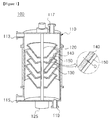
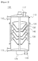
- FIGS. 1 to 5 are cross-sectional views of an apparatus for separating gas and liquid according to a first exemplary embodiment of the present invention.
- An apparatus for separating gas and liquid 100 includes a housing 110, a rotating shaft 120 provided inside the housing 110, and a drive unit 125 configured to rotate the rotating shaft 120.
- the apparatus for separating gas and liquid 100 includes a rotating cone 130 mounted at the rotating shaft 120 to rotate about the rotating shaft 120 and having a diameter decreasing from an upper end to a lower end thereof, and a fixed cone 140 fixed in the housing 110 to be spaced apart from the rotating cone 130 and having a diameter decreasing from an upper end to a lower end thereof.
- the apparatus for separating gas and liquid 100 includes a scraper 150 configured to remove scale generated in at least one of the fixed cone 140 and the rotating cone 130, based on the rotation of the rotating shaft 120.
- the housing 110 may be formed as a hollow cylinder (a tubular cylinder) having a space formed therein for accommodating the rotating shaft 120, the rotating cone 130, the fixed cone 140, and the scraper 150. Also, the housing 110 may be a column extending in a height direction. According to one exemplary embodiment, the housing 110 may be formed of stainless steel, but the material of the housing is not necessarily limited thereto.
- the housing 110 may include a first supply unit 113 configured to supply a reactant into the housing 110, and a second supply unit 115 configured to supply a gas into the housing 110.
- the first supply unit 113 used to supply the reactant may be provided in an upper end portion (an upper end portion in a height direction) of the housing 110.
- the two or more first supply unit 113 may be provided to supply two or more reactants.
- the second supply unit 115 used to supply a gas may be provided in a lower end portion of the housing 110.
- the housing 110 may include an outlet unit 117 used to discharge a residual gas from the housing 110, and a collection unit 119 used to collect a product from the housing 110.
- the residual gas is a gas obtained after reacting with the reactant while moving toward the upper side of the housing 110. Therefore, the outlet unit 117 used to discharge the residual gas may be provided in an upper end portion of the housing 110. Also, the product is generated by reacting with the gas or being subjected to gas treatment as the reactant moves to a lower portion of the housing 110. Therefore, the collection unit 119 used to collect the product may be provided in a lower end portion of the housing 110.
- first supply unit 113 and the outlet unit 117 may be provided in the upper end portion of the housing 110
- second supply unit 115 and the collection unit 119 may be provided in the lower end portion of the housing 110.
- the positions of the first supply unit 113, the second supply unit 115, the outlet unit 117, and the collection unit 119 are illustratively shown, but the present invention is not necessarily limited thereto.
- the first supply unit 113 may be formed in a lateral surface of the upper end portion of the housing 110, and the outlet unit 117 may be formed in a top surface of the housing 110.
- the first supply unit 113 may be formed in the top surface of the housing 110, and the outlet unit 117 may be formed in the lateral surface of the upper end portion of the housing 110.
- the rotating shaft 120 serves to rotate the rotating cone 130, and is formed inside the housing 110 in a height direction (for example, a vertical direction) of the housing 110.
- the rotating shaft 120 is coupled to the drive unit 125 such as a motor, and the drive unit 125 serves to rotate the rotating shaft 120.
- the rotating cone 130 is mounted at the rotating shaft 120 to rotate about the rotating shaft 120.
- the rotating cone 130 may have a diameter decreasing from an upper end to a lower end thereof, based on the height direction of the housing 110.
- the rotating cone 130 may be formed in a tubular shape in which the rotating cone 130 has a diameter decreasing from the upper end to the lower end thereof.
- the fixed cone 140 is fixed in the housing 110 to be spaced apart from the rotating cone 130.
- the fixed cone 140 may have a diameter decreasing from an upper end to a lower end thereof, based on the height direction of the housing 110.
- the fixed cone 140 may be formed in a tubular shape in which the fixed cone 140 has a diameter decreasing from the upper end to the lower end thereof.
- the scraper serves to remove scale generated in at least one of the fixed cone 140 and the rotating cone 130, based on the rotation of the rotating shaft 120.
- the rotating cone 130 and the fixed cone 140 may be alternately disposed in a height direction of the rotating shaft 120. Also, the plurality of rotating cones 130 may be mounted at the rotating shaft 120 at predetermined distances. Also, the plurality of fixed cones 140 may be fixed in the housing 110 at predetermined distances.
- the reactant supplied into the housing 110 moves in an upper end direction of the rotating cone 130 by means of a centrifugal force generated while the rotating cone 130 is rotated, and then is separated from the rotating cone 130, and transferred to the fixed cone 140.
- the rotating cone 130 has a lower end portion mounted at the rotating shaft 120. Therefore, when the rotating shaft 120 rotates by means of the drive unit 125, the rotating cone 130 may rotate about the rotating shaft 120. Also, the rotating cone 130 may be formed in a tubular shape in which the rotating cone 130 has a diameter decreasing from the upper end to the lower end thereof, and the rotating cone 130 may be generally formed in a "V" shape, as viewed from a vertical section thereof.
- the reactant When the reactant is introduced into such a rotating cone 130, the reactant spreads along the rotating cone 130 in the form of a thin film by means of a centrifugal force, moves from the upper end thereof, and then is transferred to the fixed cone 140.
- the fixed cone 140 may be formed inside the housing 110, and may be formed in a tubular shape in which the fixed cone 140 has a diameter decreasing from the upper end to the lower end thereof, and the fixed cone 140 may be generally formed in a "V" shape, as viewed from a vertical section thereof.
- the fixed cone 140 may be spaced apart from the rotating cone 130, and may be formed in a shape surrounding the outer circumference of the rotating cone 130. Specifically, the fixed cone 140 may be formed so that the maximum diameter of the fixed cone 140 is higher than that of the rotating cone 130. Therefore, the fixed cone 140 may receive the reactant from the rotating cone 130. Also, the fixed cone 140 and the rotating cone 130 may be alternately provided one by one inside the housing 110.
- FIGS. 6 and 7 are partial perspective views showing a scraper and a fixed cone which constitute the apparatus for separating gas and liquid according to the first exemplary embodiment of the present invention
- FIGS. 8 and 9 are cross-sectional views showing one operating state of the apparatus for separating gas and liquid according to the first exemplary embodiment of the present invention.
- the scraper 150 may serve to remove scale generated in the fixed cone 140. Also, in this specification, the scraper 150 used to remove scale generated in the fixed cone 140may be referred to as a first scraper. Specifically, the scraper 150 may be fixed in the rotating shaft 120 or the rotating cone 130, and used to remove scale generated in the fixed cone 140 while rotating with the rotating shaft 120 or the rotating cone 130.
- the scraper 150 is a bar-shaped scraper extending in a rod shape from the rotating shaft 120 or the rotating cone 130.
- the scraper 150 may periodically remove scale generated in the fixed cone 140 while rotating with the rotating shaft 120 or the rotating cone 130 since the scraper 150 extends from the rotating shaft 120 or the rotating cone 130.
- the scraper 150 may come in contact with the fixed cone 140 to remove the scale generated in the fixed cone 140.
- the scraper 150 may be spaced apart at a predetermined distance D from the fixed cone 140 in order to prevent friction between the scraper 150 and the fixed cone 140. In this case, when the scale is generated in the fixed cone 140 to a thickness a certain thickness, the scale may be removed by the scraper 150.
- the scraper 150 extends from the rotating shaft 120 or the rotating cone 130 toward the fixed cone 140.
- the scraper 150 may be spaced apart at a predetermined distance D from the fixed cone 140, based on the thickness of the scale generated in the fixed cone 140.
- a fixed end of the scraper 150 is coupled to the rotating shaft 120 or the rotating cone 130, and a free end of the scraper 150 extends from the fixed end toward the fixed cone 140.
- the free end of the scraper 150 may be spaced apart at a predetermined distance D from the fixed cone 140.
- the scraper 150 may burst the bubbles to prevent or inhibit growth of the scale.
- the position of the scraper 150 is not particularly limited as long as the scraper 150 may remove the scale generated in the fixed cone 140. Referring to FIGS. 1 , 3 and 4 , however, the scraper 150 may extend to face an outer circumferential surface of the fixed cone 140 in order to remove the scale generated in the outer circumferential surface of the fixed cone 140.
- the outer circumferential surface of the fixed cone 140 may refer to a surface facing the housing 110, and an inner circumferential surface of the fixed cone 140 may refer to a surface facing the rotating shaft 120.
- an outer circumferential surface of the rotating cone 130 may refer to a surface facing the housing 110, and an inner circumferential surface of the rotating cone 130 may refer to a surface facing the rotating shaft 120.
- the scraper 150 may extend to face the inner circumferential surface of the fixed cone 140 in order to remove scale generated in the inner circumferential surface of the fixed cone 140.
- the scraper 150 may extend from the rotating shaft 120.
- the scraper 150 may extend from the rotating cone 130.
- the scraper 150 may extend parallel to a first imaginary line segment ⁇ which is parallel to the rotating shaft 120 connecting an upper end portion of the fixed cone 140 to a lower end portion of the fixed cone 140 at the shortest length. Specifically, the scraper 150 may extend so that at least a portion of the scraper 150 may be parallel to the rotating shaft 120.
- the scraper 150 may extend at a predetermined angle with respect to the first line segment ⁇ . Specifically, the scraper 150 may extend so that at least a portion of the scraper 150 may be inclined at a predetermined angle with respect to the rotating shaft 120.
- the scraper 150 when the scraper 150 extends parallel to the first line segment ⁇ , the scraper 150 may be formed at a relatively short length. Therefore, it may be easy to design the scraper 150.
- the number of the scraper 150 in the drawings is one, but the present invention is not limited thereto.
- the plurality of scrapers 150 may also be provided.
- the drive unit 125 may be driven to rotate the rotating cone 130 and supply a reactant A to the housing 110 via the first supply unit 113.
- a gas B may be supplied to the housing 110 via the second supply unit 115.
- the reactant A is not particularly limited as long as the reactant A is a polymer including a volatile monomer.
- the reactant A may be one selected from the group consisting of PVC, SBR, NBR, ABS, and PBL latex.
- the gas B may be high-temperature steam capable of applying heat to the reactant.
- the reactant A supplied into the housing 110 is transferred to the rotating cone 130, and then moves toward the upper end of the rotating cone 130 by means of a centrifugal force. After that, the reactant is separated from the rotating cone 130, and transferred to the fixed cone 140.
- the reactant transferred to the fixed cone 140 moves toward the lower end of the fixed cone 140 along the slope of the fixed cone 140, and is then separated from the fixed cone 140, and transferred to the rotating cone 130 again.
- the gas B supplied into the housing 110 reacts with the reactant while moving the housing 110 upward.
- the reactant since the reactant thinly spreads by means of the centrifugal force of the rotating cone 130, the reactant may react with the gas over a large area.
- the reactant reacts with the gas as described above, a volatile organic compound is removed from the reactant, and a residual gas including the volatile organic compound and the gas is discharged through the outlet unit 117 (C).
- the reactant (i.e., a product) from which the volatile organic compound is removed is collected into the collection unit 119 (D). Then, the scraper 150 rotates with the rotating shaft 120 or the rotating cone 130. In this case, the scraper 150 is disposed to face the fixed cone 140. Referring to FIG. 9 , the scraper 150 may periodically remove the scale generated in the fixed cone 140.
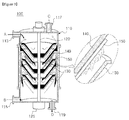
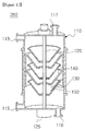
- FIGS. 10 to 13 are cross-sectional views of an apparatus for separating gas and liquid according to a second exemplary embodiment of the present invention
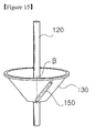
- FIGS. 14 and 15 are partial perspective views showing a scraper and a rotating cone which constitute the apparatus for separating gas and liquid according to the second exemplary embodiment of the present invention.
- the apparatus for separating gas and liquid 200 according to the second exemplary embodiment of the present invention is different from the above-described apparatus for separating gas and liquid 100 according to the first exemplary embodiment of the present invention in view of the position of the scraper 150 and a subject from which scale is removed.
- the scraper 150 constituting the apparatus for separating gas and liquid 200 according to the second exemplary embodiment serves to remove scale generated in the rotating cone 130. Also, in this specification, the scraper 150 configured to remove scale generated in the fixed cone 140 may be referred to as a second scraper.
- the scraper 150 may be a bar-shaped scraper extending in a rod shape from the housing 110 or the fixed cone 140.
- the scraper 150 since the scraper 150 extends from the housing 110 or the fixed cone 140, the scraper 150 is maintained in a fixed posture regardless of the rotation of the rotating shaft 120. Therefore, when the rotating cone 130 rotates, relative rotational displacement occurs on the fixed scraper 150 with respect to the rotating cone 130. As a result, the scraper 150 may periodically remove the scale generated in the rotating cone 130.
- the scraper 150 may come in contact with the rotating cone 130 to remove the scale generated in the rotating cone 130.
- the scraper 150 may be spaced apart at a predetermined distance D from the rotating cone 130 in order to prevent friction between the scraper 150 and the rotating cone 130. In this case, when the scale is generated in the rotating cone 130 to a certain thickness or higher, the scale may be removed by the scraper 150.
- the scraper 150 extends from an inner circumferential surface of the housing 110 or the fixed cone 140 toward the rotating cone 130.
- the scraper 150 may be spaced apart at a predetermined distance D from the rotating cone 130, based on the thickness of scale to be generated in the rotating cone 130.
- a fixed end of the scraper 150 is coupled to the housing 110 or the fixed cone 140, and a free end of the scraper 150 extends from the fixed end toward the rotating cone 130.
- the free end of the scraper 150 may be spaced apart at a predetermined distance D from the rotating cone 130.
- the scraper 150 may burst the bubbles to prevent or inhibit growth of the scale. Meanwhile, the position of the scraper 150 is not particularly limited as long as the scraper 150 may remove the scale generated in the rotating cone 130.
- the scraper 150 may extend to face an outer circumferential surface of the rotating cone 130 in order to remove scale generated in the outer circumferential surface of the rotating cone 130.
- the scraper 150 may also extend to face an inner circumferential surface of the rotating cone 130 in order to remove scale generated in the inner circumferential surface of the rotating cone 130.
- the scraper 150 may extend from the housing 110.
- the scraper 150 may extend from the fixed cone 140.
- the scraper 150 may extend parallel to a second imaginary line segment ⁇ which is parallel to the rotating shaft 120 connecting an upper end portion of the rotating cone 130 to a lower end portion of the rotating cone 130 at the shortest length. Also, the scraper 150 may extend so that at least a portion of the scraper 150 may be parallel to the rotating shaft 120.
- the scraper 150 may also extend at a predetermined angle with respect to the second line segment ⁇ . Also, the scraper 150 may extend so that at least a portion of the scraper 150 may be inclined at a predetermined angle with respect to the rotating shaft 120.
- the scraper 150 when the scraper 150 extends parallel to the second line segment ⁇ , the scraper 150 may be formed at a relatively short length. Therefore, it may be easy to design the scraper 150.
- the number of the scraper 150 in the drawings is one, but the present invention is not limited thereto.
- the plurality of scrapers 150 may also be provided.
- the apparatuses for separating gas and liquid 100 and 200 may be gas/liquid reactors used to remove volatile organic compounds from the reactant by reaction between the reactant and the gas.
- the reactant may not necessarily and chemically react with the gas.
- the apparatuses for separating gas and liquid 100 and 200 according to the exemplary embodiments of the present invention may be used to separate a material through the contact with the gas.
- the apparatus for separating gas and liquides 100 and 200 according to the exemplary embodiments of the present invention may be used to separate a material (for example, a volatile substance, etc.) included in a liquid-phase mixture by bringing the liquid-phase mixture into contact with a gas (especially a high-temperature gas).
- the mixture is not particularly limited as long as it is a binary component mixture in which a gas-phase material is dissolved in a liquid-phase material.
- the mixture may be a ternary component mixture further including a solid-phase material. That is, the apparatuses for separating gas and liquid 100 and 200 according to the exemplary embodiments of the present invention may be used to separate the ternary component material as well as the binary component material.
- Each of the apparatuses for separating gas and liquid may include both of a first scraper configured to remove scale generated in the fixed cone, based on the rotation of the rotating shaft, and a second scraper configured to remove scale generated in the rotating cone, based on the rotation of the rotating shaft.
Landscapes
- Chemical & Material Sciences (AREA)
- Chemical Kinetics & Catalysis (AREA)
- Organic Chemistry (AREA)
- Physics & Mathematics (AREA)
- Geometry (AREA)
- Health & Medical Sciences (AREA)
- Toxicology (AREA)
- General Health & Medical Sciences (AREA)
- Vaporization, Distillation, Condensation, Sublimation, And Cold Traps (AREA)
- Degasification And Air Bubble Elimination (AREA)
- Life Sciences & Earth Sciences (AREA)
- Hydrology & Water Resources (AREA)
- Engineering & Computer Science (AREA)
- Environmental & Geological Engineering (AREA)
- Water Supply & Treatment (AREA)
Abstract
Description
- The present invention relates to an apparatus for separating gas and liquid, and more particularly, to an apparatus for separating gas and liquid capable of removing scale generated in a fixed cone and a rotating cone.
- Generally, reaction apparatuses are required to prepare products through a chemical reaction. A batch-type reactor in which raw material products are added into, and then stirred in one reactor has been usually used as such reaction apparatuses. However, when the batch-type reactor is used, a large amount of non-raw material products may be generated since a sufficient reaction does not occur on reactions requiring a rapid mass transfer rate. Also, when a catalyst is used, a process of separating the catalyst is essentially required, resulting in an increase in cost in use of a large-scaled batch-type reactor.
-
Korean Patent No. 10-961,765 - In the case of the spinning cone column, rotating cones and fixed cones are alternately installed inside one column. However, the spinning cone column has no means capable of removing scale generated in the rotating cones or fixed cones. When such scale grows into lump, the lump may be separated to disturb an operation of the apparatus.
- The present invention is directed to providing an apparatus for separating gas and liquid capable of effectively removing scale generated in a rotating cone or a fixed cone.
- To solve the prior-art problems, one aspect of the present invention provides an apparatus for separating gas and liquid including a housing, a rotating shaft provided inside the housing, a drive unit configured to rotate the rotating shaft, a rotating cone mounted at the rotating shaft to rotate about the rotating shaft and having a diameter decreasing from an upper end to a lower end thereof, a fixed cone fixed in the housing to be spaced apart from the rotating cone and having a diameter decreasing from an upper end to a lower end thereof, and a scraper configured to remove scale generated in at least one of the fixed cone and the rotating cone, based on the rotation of the rotating shaft.
- Here, the scraper may be fixed in the rotating shaft or the rotating cone, and configured to remove scale generated in the fixed cone while rotating with the rotating shaft or the rotating cone.
- Also, the scraper may extend from the rotating shaft or the rotating cone toward the fixed cone.
- In addition, the scraper may be spaced apart at a predetermined distance from the fixed cone.
- Additionally, the scraper may extend to face an outer circumferential surface of the fixed cone.
- Further, the scraper may extend to face an inner circumferential surface of the fixed cone.
- Also, the scraper may extend parallel to the rotating shaft.
- In addition, the scraper may extend at a predetermined angle with respect to the rotating shaft.
- Meanwhile, the scraper may be fixed in the housing or the fixed cone, and configured to remove scale generated in the rotating cone while the rotating cone is rotated.
- Also, the scraper may extend from the housing or the fixed cone toward the rotating cone.
- In addition, the scraper may be spaced apart at a predetermined distance from the rotating cone.
- Additionally, the scraper may extend to face an outer circumferential surface of the rotating cone.
- Further, the scraper may extend to face an inner circumferential surface of the rotating cone.
- Also, the scraper may extend parallel to the rotating shaft.
- In addition, the scraper may extend at a predetermined angle with respect to the rotating shaft.
- Another aspect of the present invention provides an apparatus for separating gas and liquid including a housing, a rotating shaft provided inside the housing, a drive unit configured to rotate the rotating shaft, a rotating cone mounted at the rotating shaft to rotate about the rotating shaft and having diameter decreasing from an upper end to a lower end thereof, a fixed cone fixed in the housing to be spaced apart from the rotating cone and having a diameter decreasing from an upper end to a lower end thereof, a first scraper configured to remove scale generated in the fixed cone, based on the rotation of the rotating shaft, and a second scraper configured to remove scale generated in the rotating cone, based on the rotation of the rotating shaft.
- Here, the first scraper may be fixed in the rotating shaft or the rotating cone, and configured to remove scale generated in the fixed cone while rotating with the rotating shaft or the rotating cone.
- Also, the first scraper may extend from the rotating shaft or the rotating cone toward the fixed cone, and the first scraper may be spaced apart at a predetermined distance from the fixed cone, based on the thickness of scale to be generated in the fixed cone.
- In addition, the second scraper may be fixed in the housing or the fixed cone, and configured to remove scale generated in the rotating cone while the rotating shaft is rotated.
- Additionally, the second scraper may extend from the housing or the fixed cone toward the rotating cone, and the second scraper mat be spaced apart at a predetermined distance from the rotating cone, based on the thickness of scale to be generated in the rotating cone.
- As described above, the apparatus for separating gas and liquid according to at least one exemplary embodiment of the present invention has the following effects.
- Scale generated in at least one of the rotating cone and the fixed cone may be effectively removed by means of the scraper.
- Also, the removal of the scale by the scraper is performed based on the rotation of the rotating cone, and thus no separate drive source used to drive the scraper is required.
-
-
FIGS. 1 to 5 are cross-sectional views of an apparatus for separating gas and liquid according to a first exemplary embodiment of the present invention. -
FIGS. 6 and7 are partial perspective views showing a scraper and a fixed cone which constitute the apparatus for separating gas and liquid according to the first exemplary embodiment of the present invention. -
FIGS. 8 and9 are cross-sectional views showing one operating state of the apparatus for separating gas and liquid according to the first exemplary embodiment of the present invention. -
FIGS. 10 to 13 are cross-sectional views of an apparatus for separating gas and liquid according to a second exemplary embodiment of the present invention. -
FIGS. 14 and15 are partial perspective views showing a scraper and a rotating cone which constitute the apparatus for separating gas and liquid according to the second exemplary embodiment of the present invention. - Hereinafter, apparatuses for separating gas and liquid according to various exemplary embodiments of the present invention will be described in detail with reference to the accompanying drawings.
- Also, regardless of the reference numerals in the drawings, like or corresponding elements have the same or similar reference numerals, and a description thereof is omitted for clarity. In this case, the shapes and dimensions of elements shown in the drawings may be exaggerated or diminished for the sake of convenience of description.
-
FIGS. 1 to 5 are cross-sectional views of an apparatus for separating gas and liquid according to a first exemplary embodiment of the present invention. - An apparatus for separating gas and
liquid 100 according to the first exemplary embodiment of the present invention includes ahousing 110, a rotatingshaft 120 provided inside thehousing 110, and adrive unit 125 configured to rotate the rotatingshaft 120. - Also, the apparatus for separating gas and
liquid 100 includes a rotatingcone 130 mounted at the rotatingshaft 120 to rotate about the rotatingshaft 120 and having a diameter decreasing from an upper end to a lower end thereof, and afixed cone 140 fixed in thehousing 110 to be spaced apart from the rotatingcone 130 and having a diameter decreasing from an upper end to a lower end thereof. - In addition, the apparatus for separating gas and
liquid 100 includes ascraper 150 configured to remove scale generated in at least one of thefixed cone 140 and the rotatingcone 130, based on the rotation of therotating shaft 120. - The
housing 110 may be formed as a hollow cylinder (a tubular cylinder) having a space formed therein for accommodating the rotatingshaft 120, the rotatingcone 130, thefixed cone 140, and thescraper 150. Also, thehousing 110 may be a column extending in a height direction. According to one exemplary embodiment, thehousing 110 may be formed of stainless steel, but the material of the housing is not necessarily limited thereto. - Also, the
housing 110 may include afirst supply unit 113 configured to supply a reactant into thehousing 110, and asecond supply unit 115 configured to supply a gas into thehousing 110. - Here, since the reactant moves downward (to a lower end portion of the
housing 110 in a height direction) due to the gravity, thefirst supply unit 113 used to supply the reactant may be provided in an upper end portion (an upper end portion in a height direction) of thehousing 110. In this case, the two or morefirst supply unit 113 may be provided to supply two or more reactants. - Also, since the gas reacts with the reactant while moving in an upper direction opposite to that of the reactant (toward an upper end portion of the
housing 110 in a height direction), thesecond supply unit 115 used to supply a gas may be provided in a lower end portion of thehousing 110. - Meanwhile, the
housing 110 may include anoutlet unit 117 used to discharge a residual gas from thehousing 110, and acollection unit 119 used to collect a product from thehousing 110. - Here, the residual gas is a gas obtained after reacting with the reactant while moving toward the upper side of the
housing 110. Therefore, theoutlet unit 117 used to discharge the residual gas may be provided in an upper end portion of thehousing 110. Also, the product is generated by reacting with the gas or being subjected to gas treatment as the reactant moves to a lower portion of thehousing 110. Therefore, thecollection unit 119 used to collect the product may be provided in a lower end portion of thehousing 110. - Specifically, the
first supply unit 113 and theoutlet unit 117 may be provided in the upper end portion of thehousing 110, and thesecond supply unit 115 and thecollection unit 119 may be provided in the lower end portion of thehousing 110. - However, the positions of the
first supply unit 113, thesecond supply unit 115, theoutlet unit 117, and thecollection unit 119 are illustratively shown, but the present invention is not necessarily limited thereto. For example, referring toFIG. 1 , thefirst supply unit 113 may be formed in a lateral surface of the upper end portion of thehousing 110, and theoutlet unit 117 may be formed in a top surface of thehousing 110. On the other hand, referring toFIG. 3 , thefirst supply unit 113 may be formed in the top surface of thehousing 110, and theoutlet unit 117 may be formed in the lateral surface of the upper end portion of thehousing 110. - The
rotating shaft 120 serves to rotate therotating cone 130, and is formed inside thehousing 110 in a height direction (for example, a vertical direction) of thehousing 110. - Here, the
rotating shaft 120 is coupled to thedrive unit 125 such as a motor, and thedrive unit 125 serves to rotate therotating shaft 120. - Meanwhile, the
rotating cone 130 is mounted at therotating shaft 120 to rotate about therotating shaft 120. Also, therotating cone 130 may have a diameter decreasing from an upper end to a lower end thereof, based on the height direction of thehousing 110. Specifically, therotating cone 130 may be formed in a tubular shape in which therotating cone 130 has a diameter decreasing from the upper end to the lower end thereof. - Also, the fixed
cone 140 is fixed in thehousing 110 to be spaced apart from therotating cone 130. Also, the fixedcone 140 may have a diameter decreasing from an upper end to a lower end thereof, based on the height direction of thehousing 110. Specifically, the fixedcone 140 may be formed in a tubular shape in which the fixedcone 140 has a diameter decreasing from the upper end to the lower end thereof. - In addition, the scraper serves to remove scale generated in at least one of the fixed
cone 140 and therotating cone 130, based on the rotation of therotating shaft 120. - The
rotating cone 130 and the fixedcone 140 may be alternately disposed in a height direction of therotating shaft 120. Also, the plurality ofrotating cones 130 may be mounted at therotating shaft 120 at predetermined distances. Also, the plurality of fixedcones 140 may be fixed in thehousing 110 at predetermined distances. - Meanwhile, the reactant supplied into the
housing 110 moves in an upper end direction of therotating cone 130 by means of a centrifugal force generated while therotating cone 130 is rotated, and then is separated from therotating cone 130, and transferred to the fixedcone 140. - Specifically, the
rotating cone 130 has a lower end portion mounted at therotating shaft 120. Therefore, when therotating shaft 120 rotates by means of thedrive unit 125, therotating cone 130 may rotate about therotating shaft 120. Also, therotating cone 130 may be formed in a tubular shape in which therotating cone 130 has a diameter decreasing from the upper end to the lower end thereof, and therotating cone 130 may be generally formed in a "V" shape, as viewed from a vertical section thereof. - When the reactant is introduced into such a
rotating cone 130, the reactant spreads along therotating cone 130 in the form of a thin film by means of a centrifugal force, moves from the upper end thereof, and then is transferred to the fixedcone 140. - Meanwhile, the fixed
cone 140 may be formed inside thehousing 110, and may be formed in a tubular shape in which the fixedcone 140 has a diameter decreasing from the upper end to the lower end thereof, and the fixedcone 140 may be generally formed in a "V" shape, as viewed from a vertical section thereof. - In this case, the fixed
cone 140 may be spaced apart from therotating cone 130, and may be formed in a shape surrounding the outer circumference of therotating cone 130. Specifically, the fixedcone 140 may be formed so that the maximum diameter of the fixedcone 140 is higher than that of therotating cone 130. Therefore, the fixedcone 140 may receive the reactant from therotating cone 130. Also, the fixedcone 140 and therotating cone 130 may be alternately provided one by one inside thehousing 110. -
FIGS. 6 and7 are partial perspective views showing a scraper and a fixed cone which constitute the apparatus for separating gas and liquid according to the first exemplary embodiment of the present invention, andFIGS. 8 and9 are cross-sectional views showing one operating state of the apparatus for separating gas and liquid according to the first exemplary embodiment of the present invention. - The
scraper 150 may serve to remove scale generated in the fixedcone 140. Also, in this specification, thescraper 150 used to remove scale generated in the fixed cone 140may be referred to as a first scraper. Specifically, thescraper 150 may be fixed in therotating shaft 120 or therotating cone 130, and used to remove scale generated in the fixedcone 140 while rotating with therotating shaft 120 or therotating cone 130. - Here, the
scraper 150 is a bar-shaped scraper extending in a rod shape from therotating shaft 120 or therotating cone 130. In this case, thescraper 150 may periodically remove scale generated in the fixedcone 140 while rotating with therotating shaft 120 or therotating cone 130 since thescraper 150 extends from therotating shaft 120 or therotating cone 130. - Also, the
scraper 150 may come in contact with the fixedcone 140 to remove the scale generated in the fixedcone 140. On the other hand, referring toFIG. 1 , thescraper 150 may be spaced apart at a predetermined distance D from the fixedcone 140 in order to prevent friction between thescraper 150 and the fixedcone 140. In this case, when the scale is generated in the fixedcone 140 to a thickness a certain thickness, the scale may be removed by thescraper 150. - In addition, the
scraper 150 extends from therotating shaft 120 or therotating cone 130 toward the fixedcone 140. Here, thescraper 150 may be spaced apart at a predetermined distance D from the fixedcone 140, based on the thickness of the scale generated in the fixedcone 140. Specifically, a fixed end of thescraper 150 is coupled to therotating shaft 120 or therotating cone 130, and a free end of thescraper 150 extends from the fixed end toward the fixedcone 140. Also, the free end of thescraper 150 may be spaced apart at a predetermined distance D from the fixedcone 140. - Additionally, when bubbles are formed on the fixed
cone 140, thescraper 150 may burst the bubbles to prevent or inhibit growth of the scale. - Meanwhile, the position of the
scraper 150 is not particularly limited as long as thescraper 150 may remove the scale generated in the fixedcone 140. Referring toFIGS. 1 ,3 and4 , however, thescraper 150 may extend to face an outer circumferential surface of the fixedcone 140 in order to remove the scale generated in the outer circumferential surface of the fixedcone 140. - Also, the outer circumferential surface of the fixed
cone 140 may refer to a surface facing thehousing 110, and an inner circumferential surface of the fixedcone 140 may refer to a surface facing therotating shaft 120. Similarly, an outer circumferential surface of therotating cone 130 may refer to a surface facing thehousing 110, and an inner circumferential surface of therotating cone 130 may refer to a surface facing therotating shaft 120. - On the other hand, referring to
FIGS. 2 and5 , thescraper 150 may extend to face the inner circumferential surface of the fixedcone 140 in order to remove scale generated in the inner circumferential surface of the fixedcone 140. - Meanwhile, referring to
FIGS. 1 to 3 , thescraper 150 may extend from therotating shaft 120. On the other hand, referring toFIGS. 4 and5 , thescraper 150 may extend from therotating cone 130. - Referring to
FIG. 6 , thescraper 150 may extend parallel to a first imaginary line segment α which is parallel to therotating shaft 120 connecting an upper end portion of the fixedcone 140 to a lower end portion of the fixedcone 140 at the shortest length. Specifically, thescraper 150 may extend so that at least a portion of thescraper 150 may be parallel to therotating shaft 120. - On the other hand, referring to
FIG. 7 , thescraper 150 may extend at a predetermined angle with respect to the first line segment α. Specifically, thescraper 150 may extend so that at least a portion of thescraper 150 may be inclined at a predetermined angle with respect to therotating shaft 120. - Meanwhile, as shown in
FIG. 6 , when thescraper 150 extends parallel to the first line segment α, thescraper 150 may be formed at a relatively short length. Therefore, it may be easy to design thescraper 150. - On the other hand, as shown in
FIG. 7 , when thescraper 150 extends obliquely with respect to the first line segment α, a contact area between thescraper 150 and the fixedcone 140 may increase, thereby removing the scale more effectively. - In addition, the number of the
scraper 150 in the drawings is one, but the present invention is not limited thereto. For example, the plurality ofscrapers 150 may also be provided. - Referring to
FIG. 8 , thedrive unit 125 may be driven to rotate therotating cone 130 and supply a reactant A to thehousing 110 via thefirst supply unit 113. Also, a gas B may be supplied to thehousing 110 via thesecond supply unit 115. In this case, the reactant A is not particularly limited as long as the reactant A is a polymer including a volatile monomer. For example, the reactant A may be one selected from the group consisting of PVC, SBR, NBR, ABS, and PBL latex. Also, the gas B may be high-temperature steam capable of applying heat to the reactant. - Referring to
FIG. 9 , the reactant A supplied into thehousing 110 is transferred to therotating cone 130, and then moves toward the upper end of therotating cone 130 by means of a centrifugal force. After that, the reactant is separated from therotating cone 130, and transferred to the fixedcone 140. The reactant transferred to the fixedcone 140 moves toward the lower end of the fixedcone 140 along the slope of the fixedcone 140, and is then separated from the fixedcone 140, and transferred to therotating cone 130 again. - Meanwhile, the gas B supplied into the
housing 110 reacts with the reactant while moving thehousing 110 upward. In this case, since the reactant thinly spreads by means of the centrifugal force of therotating cone 130, the reactant may react with the gas over a large area. When the reactant reacts with the gas as described above, a volatile organic compound is removed from the reactant, and a residual gas including the volatile organic compound and the gas is discharged through the outlet unit 117 (C). - Also, the reactant (i.e., a product) from which the volatile organic compound is removed is collected into the collection unit 119 (D). Then, the
scraper 150 rotates with therotating shaft 120 or therotating cone 130. In this case, thescraper 150 is disposed to face the fixedcone 140. Referring toFIG. 9 , thescraper 150 may periodically remove the scale generated in the fixedcone 140. - Meanwhile, to effectively perform a reaction between the reactant and the gas, an inner pressure of the
housing 110 may be reduced or enhanced.FIGS. 10 to 13 are cross-sectional views of an apparatus for separating gas and liquid according to a second exemplary embodiment of the present invention, andFIGS. 14 and15 are partial perspective views showing a scraper and a rotating cone which constitute the apparatus for separating gas and liquid according to the second exemplary embodiment of the present invention. - Referring to
FIGS. 10 to 13 , the apparatus for separating gas and liquid 200 according to the second exemplary embodiment of the present invention is different from the above-described apparatus for separating gas and liquid 100 according to the first exemplary embodiment of the present invention in view of the position of thescraper 150 and a subject from which scale is removed. - Therefore, a description of the apparatus for separating gas and liquid 200 according to the second exemplary embodiment which is related to the same configuration as the apparatus for separating gas and liquid 100 according to the first exemplary embodiment may be omitted for clarity, and thus the apparatus for separating gas and liquid 200 according to the second exemplary embodiment will be described focusing on the
scraper 150. - The
scraper 150 constituting the apparatus for separating gas and liquid 200 according to the second exemplary embodiment serves to remove scale generated in therotating cone 130. Also, in this specification, thescraper 150 configured to remove scale generated in the fixedcone 140 may be referred to as a second scraper. - Here, the
scraper 150 may be a bar-shaped scraper extending in a rod shape from thehousing 110 or the fixedcone 140. In this case, since thescraper 150 extends from thehousing 110 or the fixedcone 140, thescraper 150 is maintained in a fixed posture regardless of the rotation of therotating shaft 120. Therefore, when therotating cone 130 rotates, relative rotational displacement occurs on the fixedscraper 150 with respect to therotating cone 130. As a result, thescraper 150 may periodically remove the scale generated in therotating cone 130. - Specifically, the
scraper 150 may come in contact with therotating cone 130 to remove the scale generated in therotating cone 130. On the other hand, referring toFIG. 10 , thescraper 150 may be spaced apart at a predetermined distance D from therotating cone 130 in order to prevent friction between thescraper 150 and therotating cone 130. In this case, when the scale is generated in therotating cone 130 to a certain thickness or higher, the scale may be removed by thescraper 150. - Also, the
scraper 150 extends from an inner circumferential surface of thehousing 110 or the fixedcone 140 toward therotating cone 130. Here, thescraper 150 may be spaced apart at a predetermined distance D from therotating cone 130, based on the thickness of scale to be generated in therotating cone 130. Specifically, a fixed end of thescraper 150 is coupled to thehousing 110 or the fixedcone 140, and a free end of thescraper 150 extends from the fixed end toward therotating cone 130. Also, the free end of thescraper 150 may be spaced apart at a predetermined distance D from therotating cone 130. - In addition, when bubbles are formed on the
rotating cone 130, thescraper 150 may burst the bubbles to prevent or inhibit growth of the scale. Meanwhile, the position of thescraper 150 is not particularly limited as long as thescraper 150 may remove the scale generated in therotating cone 130. - Referring to
FIGS. 10 and12 , however, thescraper 150 may extend to face an outer circumferential surface of therotating cone 130 in order to remove scale generated in the outer circumferential surface of therotating cone 130. - Referring to
FIGS. 11 and13 , thescraper 150 may also extend to face an inner circumferential surface of therotating cone 130 in order to remove scale generated in the inner circumferential surface of therotating cone 130. - Meanwhile, referring to
FIGS. 10 and11 , thescraper 150 may extend from thehousing 110. On the other hand, referring toFIGS. 12 and13 , thescraper 150 may extend from the fixedcone 140. - Meanwhile, referring to
FIG. 14 , thescraper 150 may extend parallel to a second imaginary line segment β which is parallel to therotating shaft 120 connecting an upper end portion of therotating cone 130 to a lower end portion of therotating cone 130 at the shortest length. Also, thescraper 150 may extend so that at least a portion of thescraper 150 may be parallel to therotating shaft 120. - Referring to
FIG. 15 , thescraper 150 may also extend at a predetermined angle with respect to the second line segment β. Also, thescraper 150 may extend so that at least a portion of thescraper 150 may be inclined at a predetermined angle with respect to therotating shaft 120. - As shown in
FIG. 14 , when thescraper 150 extends parallel to the second line segment β, thescraper 150 may be formed at a relatively short length. Therefore, it may be easy to design thescraper 150. - On the other hand, as shown in
FIG. 15 , when thescraper 150 extends obliquely with respect to the second line segment β, a contact area between thescraper 150 and therotating cone 130 may increase, thereby removing the scale more effectively. - Additionally, the number of the
scraper 150 in the drawings is one, but the present invention is not limited thereto. For example, the plurality ofscrapers 150 may also be provided. - As described above, the apparatuses for separating gas and
liquid - However, the reactant may not necessarily and chemically react with the gas. For example, the apparatuses for separating gas and
liquid - However, the mixture is not particularly limited as long as it is a binary component mixture in which a gas-phase material is dissolved in a liquid-phase material. For example, the mixture may be a ternary component mixture further including a solid-phase material. That is, the apparatuses for separating gas and
liquid - Up to now, the apparatus for separating gas and liquid 100 according to the first exemplary embodiment including the first scraper and the apparatus for separating gas and liquid 200 according to the second exemplary embodiment including the second scraper have been described separately.
- Each of the apparatuses for separating gas and liquid according to other exemplary embodiments of the present invention may include both of a first scraper configured to remove scale generated in the fixed cone, based on the rotation of the rotating shaft, and a second scraper configured to remove scale generated in the rotating cone, based on the rotation of the rotating shaft.
- The present invention has been described in detail. However, it should be understood that the detailed description and specific examples, while indicating preferred embodiments of the invention, are given by way of illustration only, since various changes and modifications within the spirit and scope of the invention will become apparent to those skilled in the art from this detailed description.
[Brief Description of Main Parts in the Drawings] 100, 200: apparatus for separating gas and liquid 110: housing 113: first supply unit 115: second supply unit 117: outlet unit 119: collection unit 120: rotating shaft 25: drive unit 130: rotating cone 40: fixed cone 150: scraper α: first line segment β: second line segment
Claims (20)
- An apparatus for separating gas and liquid comprising:a housing;a rotating shaft provided inside the housing;a drive unit configured to rotate the rotating shaft;a rotating cone mounted at the rotating shaft to rotate about the rotating shaft and having a diameter decreasing from an upper end to a lower end thereof;a fixed cone fixed in the housing to be spaced apart from the rotating cone and having a diameter decreasing from an upper end to a lower end thereof; anda scraper configured to remove scale generated in at least one of the fixed cone and the rotating cone, based on the rotation of the rotating shaft.
- The apparatus for separating gas and liquid of claim 1, wherein the scraper is fixed in the rotating shaft or the rotating cone, and configured to remove scale generated in the fixed cone while rotating with the rotating shaft or the rotating cone.
- The apparatus for separating gas and liquid of claim 2, wherein the scraper extends from the rotating shaft or the rotating cone toward the fixed cone.
- The apparatus for separating gas and liquid of claim 3, wherein the scraper is spaced apart at a predetermined distance from the fixed cone.
- The apparatus for separating gas and liquid of claim 3, wherein the scraper extends to face an outer circumferential surface of the fixed cone.
- The apparatus for separating gas and liquid of claim 3, wherein the scraper extends to face an inner circumferential surface of the fixed cone.
- The apparatus for separating gas and liquid of claim 3, wherein the scraper extends parallel to the rotating shaft.
- The apparatus for separating gas and liquid of claim 3, wherein the scraper extends at a predetermined angle with respect to the rotating shaft.
- The apparatus for separating gas and liquid of claim 1, wherein the scraper is fixed in the housing or the fixed cone, and configured to remove scale generated in the rotating cone while the rotating cone is rotated.
- The apparatus for separating gas and liquid of claim 9, wherein the scraper extends from the housing or the fixed cone toward the rotating cone.
- The apparatus for separating gas and liquid of claim 10, wherein the scraper is spaced apart at a predetermined distance from the rotating cone.
- The apparatus for separating gas and liquid of claim 10, wherein the scraper extends to face an outer circumferential surface of the rotating cone.
- The apparatus for separating gas and liquid of claim 10, wherein the scraper extends to face an inner circumferential surface of the rotating cone.
- The apparatus for separating gas and liquid of claim 10, wherein the scraper extends parallel to the rotating shaft.
- The apparatus for separating gas and liquid of claim 10, wherein the scraper extends at a predetermined angle with respect to the rotating shaft.
- An apparatus for separating gas and liquid comprising:a housing;a rotating shaft provided inside the housing;a drive unit configured to rotate the rotating shaft;a rotating cone mounted at the rotating shaft to rotate about the rotating shaft and having diameter decreasing from an upper end to a lower end thereof;a fixed cone fixed in the housing to be spaced apart from the rotating cone and having a diameter decreasing from an upper end to a lower end thereof;a first scraper configured to remove scale generated in the fixed cone, based on the rotation of the rotating shaft; anda second scraper configured to remove scale generated in the rotating cone, based on the rotation of the rotating shaft.
- The apparatus for separating gas and liquid of claim 16, wherein the first scraper is fixed in the rotating shaft or the rotating cone, and configured to remove scale generated in the fixed cone while rotating with the rotating shaft or the rotating cone.
- The apparatus for separating gas and liquid of claim 17, wherein the first scraper extends from the rotating shaft or the rotating cone toward the fixed cone, and
the first scraper is spaced apart at a predetermined distance from the fixed cone, based on the thickness of scale to be generated in the fixed cone. - The apparatus for separating gas and liquid of claim 17, wherein the second scraper is fixed in the housing or the fixed cone, and configured to remove scale generated in the rotating cone while the rotating shaft is rotated.
- The apparatus for separating gas and liquid of claim 17, wherein the second scraper extends from the housing or the fixed cone toward the rotating cone, and
the second scraper is spaced apart at a predetermined distance from the rotating cone, based on the thickness of scale to be formed in the rotating cone.
Applications Claiming Priority (3)
| Application Number | Priority Date | Filing Date | Title |
|---|---|---|---|
| KR20130084551 | 2013-07-18 | ||
| KR1020140090324A KR101620177B1 (en) | 2013-07-18 | 2014-07-17 | Apparatus for separating gas and liquid |
| PCT/KR2014/006525 WO2015009093A1 (en) | 2013-07-18 | 2014-07-18 | Gas-liquid separation apparatus |
Publications (3)
| Publication Number | Publication Date |
|---|---|
| EP3023133A1 true EP3023133A1 (en) | 2016-05-25 |
| EP3023133A4 EP3023133A4 (en) | 2017-03-15 |
| EP3023133B1 EP3023133B1 (en) | 2023-05-10 |
Family
ID=52482381
Family Applications (1)
| Application Number | Title | Priority Date | Filing Date |
|---|---|---|---|
| EP14826612.5A Active EP3023133B1 (en) | 2013-07-18 | 2014-07-18 | Gas-liquid separation apparatus |
Country Status (6)
| Country | Link |
|---|---|
| US (1) | US9446332B2 (en) |
| EP (1) | EP3023133B1 (en) |
| JP (1) | JP6098958B2 (en) |
| KR (1) | KR101620177B1 (en) |
| CN (1) | CN104870071B (en) |
| WO (1) | WO2015009093A1 (en) |
Families Citing this family (7)
| Publication number | Priority date | Publication date | Assignee | Title |
|---|---|---|---|---|
| KR101815346B1 (en) | 2014-12-16 | 2018-01-04 | 주식회사 엘지화학 | Apparatus for separating liquid-gas |
| KR102101158B1 (en) * | 2015-11-30 | 2020-04-16 | 주식회사 엘지화학 | Reactor |
| KR20180075814A (en) * | 2016-12-27 | 2018-07-05 | 한화케미칼 주식회사 | distillation |
| KR102577190B1 (en) * | 2019-11-05 | 2023-09-11 | 한화솔루션 주식회사 | distillation apparatus |
| KR102660991B1 (en) * | 2019-11-05 | 2024-04-25 | 한화솔루션 주식회사 | distillation apparatus |
| CN116355216B (en) * | 2023-04-19 | 2023-09-15 | 浙江佳汇新材料有限公司 | Preparation process of low-viscosity methyl silicone oil |
| CN118217885B (en) * | 2024-05-20 | 2024-08-06 | 湘潭华宇电炉制造有限公司 | Full-automatic closed continuous production equipment for selenium oxidation |
Family Cites Families (36)
| Publication number | Priority date | Publication date | Assignee | Title |
|---|---|---|---|---|
| US1503657A (en) * | 1920-04-26 | 1924-08-05 | Dorr Co | Process of manufacturing sugar |
| NL19269C (en) * | 1925-01-05 | 1900-01-01 | ||
| US1602014A (en) * | 1925-01-05 | 1926-10-05 | Gilchrist & Company | Process and apparatus for separating substances from liquids |
| US1595066A (en) * | 1925-07-22 | 1926-08-10 | Booth Levis Miller | Settling tank |
| US1780655A (en) * | 1928-11-02 | 1930-11-04 | Nyrop Aage | Sludge separator |
| US1830516A (en) * | 1929-10-22 | 1931-11-03 | Jr Charles W Kurie | Compound spiral |
| US2218342A (en) * | 1938-04-06 | 1940-10-15 | Chemical Foundation Inc | Distillation column |
| US2314986A (en) * | 1939-01-14 | 1943-03-30 | Charles M Johnson | Centrifugal separator |
| US2228750A (en) * | 1939-09-07 | 1941-01-14 | Rexair Inc | Vacuum cleaner construction |
| US2606146A (en) * | 1948-06-26 | 1952-08-05 | Shell Dev | High-vacuum multistage distillation method and apparatus |
| US2698287A (en) * | 1950-03-03 | 1954-12-28 | Ici Ltd | Rotary fractionation apparatus |
| US2633930A (en) * | 1950-06-10 | 1953-04-07 | William R Carter | Centrifugal air separator for removal and classification of particles |
| US2954330A (en) * | 1955-08-08 | 1960-09-27 | Celanese Corp | Distillation column |
| BE624585A (en) * | 1961-11-22 | |||
| US3950147A (en) * | 1974-08-08 | 1976-04-13 | Kamyr, Inc. | Process for feeding coal to a fluidized bed or suspended particle pressurized processing chamber and apparatus for carrying out the same |
| DE2518201C3 (en) * | 1975-04-24 | 1979-03-15 | Battelle-Institut E.V., 6000 Frankfurt | Device for separating gas mixtures into components of different molecular masses |
| DE2951689A1 (en) * | 1979-12-21 | 1981-07-02 | Vaclav Dipl.-Ing. 7500 Karlsruhe Feres | COLUMN FOR HEAT AND FUEL EXCHANGE |
| FR2522528B1 (en) * | 1982-03-03 | 1987-05-07 | Saget Pierre | IMPROVED APPARATUS FOR CENTRIFUGAL SEPARATION OF A MIXTURE COMPRISING AT LEAST ONE GASEOUS PHASE |
| DE3346078C1 (en) * | 1983-12-21 | 1985-06-20 | Hakolb GmbH Anlagenbau, 2400 Lübeck | Apparatus for the continuous production of preserves or jams |
| FR2575677B1 (en) * | 1985-01-08 | 1987-03-20 | Saget Pierre | CENTRIFUGAL SEPARATOR FOR THE TREATMENT OF A MIXTURE COMPRISING AT LEAST ONE GASEOUS PHASE, WITH FORCED HEAVY PHASE COLLECTION |
| BR8600564A (en) * | 1985-02-11 | 1986-10-21 | Falvourtech Pty Ltd | CONTRA-CURRENT CONTACT DEVICE OR DISTILLATION COLUMN, SYSTEM TO REDUCE THE ALCOHOLIC CONTENT OF A DRINK CONTAINING ALCOHOL, SYSTEM TO REDUCE THE ALCOHOLIC CONTENT OF WINE, SYSTEM FOR REMOVING AROMA AND / OR TASTE OF FRUIT JUICE, DE-DESULFURIZING A LIQUID AND PROCESS TO DISTILL, DISTILL BY FRACTIONATION OR REMOVE A SELECTED VOLATILE COMPONENT, OR COMPONENTS OF A LIQUID |
| EP0191625B1 (en) * | 1985-02-11 | 1992-08-26 | Vamhire Pty. Limited | Improved gas-liquid contacting device and method |
| US5264124A (en) * | 1992-02-05 | 1993-11-23 | Inter-Source Recovery Systems, Inc. | Segmented centrifugal separator scroll housing with removable scroll segments |
| US6030532A (en) * | 1998-02-04 | 2000-02-29 | 9053-5998 Quebec Inc. | Solid-liquid separator and filter |
| SE9801567D0 (en) * | 1998-05-04 | 1998-05-04 | Alfa Laval Ab | Methods and plant for the purification of gases from an internal combustion engine |
| JP2002045605A (en) * | 2000-08-04 | 2002-02-12 | Ebara Corp | Trap device |
| US6514303B2 (en) * | 2001-01-09 | 2003-02-04 | Case Corporation | Rotary air screen for a work machine |
| JP4258009B2 (en) | 2004-04-30 | 2009-04-30 | 坂本香料株式会社 | Aroma component distillation recovery apparatus and assembly method or cleaning method thereof |
| US20070227357A1 (en) * | 2006-03-31 | 2007-10-04 | Mcdermott Wayne T | Turbomolecular pump system for gas separation |
| EP2242570B1 (en) * | 2007-11-29 | 2018-02-14 | Energy & Ecology S.r.l. | Method for the thermocatalytic depolymerisation of plastic material |
| CN201214025Y (en) * | 2008-04-28 | 2009-04-01 | 湖北中烟工业有限责任公司 | Rotary Steam Distillation Equipment |
| CN101612486A (en) * | 2008-06-26 | 2009-12-30 | 湖北中烟工业有限责任公司 | Rotary steam distillation equipment |
| KR100961765B1 (en) | 2008-08-18 | 2010-06-07 | 주식회사 엘지화학 | Spinning disc reactor |
| KR101235619B1 (en) | 2011-04-08 | 2013-02-21 | 주식회사 한강엔지니어링 | High purity distillation apparatus of Continuous type |
| KR101494831B1 (en) * | 2011-05-27 | 2015-02-23 | 주식회사 엘지화학 | Spinning cone column for removing Volatile Organic Compounds |
| KR101474411B1 (en) * | 2011-05-27 | 2014-12-22 | 주식회사 엘지화학 | Spinning cone column having foam eliminator |
-
2014
- 2014-07-17 KR KR1020140090324A patent/KR101620177B1/en active Active
- 2014-07-18 JP JP2015539530A patent/JP6098958B2/en active Active
- 2014-07-18 WO PCT/KR2014/006525 patent/WO2015009093A1/en not_active Ceased
- 2014-07-18 EP EP14826612.5A patent/EP3023133B1/en active Active
- 2014-07-18 CN CN201480003569.1A patent/CN104870071B/en active Active
- 2014-07-18 US US14/437,421 patent/US9446332B2/en active Active
Non-Patent Citations (1)
| Title |
|---|
| See references of WO2015009093A1 * |
Also Published As
| Publication number | Publication date |
|---|---|
| JP2016502456A (en) | 2016-01-28 |
| CN104870071B (en) | 2017-03-15 |
| KR101620177B1 (en) | 2016-05-12 |
| US9446332B2 (en) | 2016-09-20 |
| US20150274546A1 (en) | 2015-10-01 |
| EP3023133B1 (en) | 2023-05-10 |
| CN104870071A (en) | 2015-08-26 |
| WO2015009093A1 (en) | 2015-01-22 |
| EP3023133A4 (en) | 2017-03-15 |
| JP6098958B2 (en) | 2017-03-22 |
| KR20150010635A (en) | 2015-01-28 |
Similar Documents
| Publication | Publication Date | Title |
|---|---|---|
| US9446332B2 (en) | Apparatus for separating gas and liquid | |
| KR100961765B1 (en) | Spinning disc reactor | |
| KR20120132419A (en) | Spinning cone column for removing Volatile Organic Compounds | |
| CN103561859B (en) | SCC is used to remove the method for the unreacted monomer in polymer | |
| EP3023142B1 (en) | Gas-liquid separation apparatus | |
| CN106999801B (en) | Liquid gas separation device | |
| KR101617091B1 (en) | Apparatus for separating gas and liquid | |
| JP5732593B2 (en) | SCC with foam remover | |
| CN204313612U (en) | A kind of drying device for industrial chemicals and medicine | |
| KR101888349B1 (en) | Gas-liquid device | |
| KR101474476B1 (en) | Spinning cone column with enhanced mobility of removal object | |
| US7199253B2 (en) | Method of manufacturing alkylene carbonate | |
| KR100961766B1 (en) | Spinning Disc Reactor with Reactant Outlet on Disc Surface | |
| KR101702712B1 (en) | Apparatus for separating liquid-gas | |
| KR101593092B1 (en) | Spinning cone column having a form breaker | |
| JP2007153784A (en) | Purification method of sucrose fatty acid ester | |
| CN108348816B (en) | Reactor with a reactor shell | |
| CN216826144U (en) | Dicyclopentadiene refining plant | |
| JP4899972B2 (en) | How to identify a badly packed reaction tube | |
| CN114828978A (en) | Distillation apparatus | |
| KR20100021696A (en) | Spinning disc reactor |
Legal Events
| Date | Code | Title | Description |
|---|---|---|---|
| PUAI | Public reference made under article 153(3) epc to a published international application that has entered the european phase |
Free format text: ORIGINAL CODE: 0009012 |
|
| 17P | Request for examination filed |
Effective date: 20150421 |
|
| AK | Designated contracting states |
Kind code of ref document: A1 Designated state(s): AL AT BE BG CH CY CZ DE DK EE ES FI FR GB GR HR HU IE IS IT LI LT LU LV MC MK MT NL NO PL PT RO RS SE SI SK SM TR |
|
| AX | Request for extension of the european patent |
Extension state: BA ME |
|
| DAX | Request for extension of the european patent (deleted) | ||
| A4 | Supplementary search report drawn up and despatched |
Effective date: 20170210 |
|
| RIC1 | Information provided on ipc code assigned before grant |
Ipc: B01D 19/00 20060101AFI20170206BHEP Ipc: B01J 4/00 20060101ALI20170206BHEP Ipc: B01J 19/18 20060101ALI20170206BHEP |
|
| STAA | Information on the status of an ep patent application or granted ep patent |
Free format text: STATUS: EXAMINATION IS IN PROGRESS |
|
| 17Q | First examination report despatched |
Effective date: 20191008 |
|
| GRAP | Despatch of communication of intention to grant a patent |
Free format text: ORIGINAL CODE: EPIDOSNIGR1 |
|
| STAA | Information on the status of an ep patent application or granted ep patent |
Free format text: STATUS: GRANT OF PATENT IS INTENDED |
|
| INTG | Intention to grant announced |
Effective date: 20230224 |
|
| GRAS | Grant fee paid |
Free format text: ORIGINAL CODE: EPIDOSNIGR3 |
|
| GRAA | (expected) grant |
Free format text: ORIGINAL CODE: 0009210 |
|
| STAA | Information on the status of an ep patent application or granted ep patent |
Free format text: STATUS: THE PATENT HAS BEEN GRANTED |
|
| AK | Designated contracting states |
Kind code of ref document: B1 Designated state(s): AL AT BE BG CH CY CZ DE DK EE ES FI FR GB GR HR HU IE IS IT LI LT LU LV MC MK MT NL NO PL PT RO RS SE SI SK SM TR |
|
| REG | Reference to a national code |
Ref country code: GB Ref legal event code: FG4D |
|
| REG | Reference to a national code |
Ref country code: AT Ref legal event code: REF Ref document number: 1566143 Country of ref document: AT Kind code of ref document: T Effective date: 20230515 Ref country code: CH Ref legal event code: EP |
|
| REG | Reference to a national code |
Ref country code: DE Ref legal event code: R096 Ref document number: 602014086916 Country of ref document: DE |
|
| REG | Reference to a national code |
Ref country code: IE Ref legal event code: FG4D |
|
| REG | Reference to a national code |
Ref country code: LT Ref legal event code: MG9D |
|
| REG | Reference to a national code |
Ref country code: NL Ref legal event code: MP Effective date: 20230510 |
|
| REG | Reference to a national code |
Ref country code: AT Ref legal event code: MK05 Ref document number: 1566143 Country of ref document: AT Kind code of ref document: T Effective date: 20230510 |
|
| PG25 | Lapsed in a contracting state [announced via postgrant information from national office to epo] |
Ref country code: SE Free format text: LAPSE BECAUSE OF FAILURE TO SUBMIT A TRANSLATION OF THE DESCRIPTION OR TO PAY THE FEE WITHIN THE PRESCRIBED TIME-LIMIT Effective date: 20230510 Ref country code: PT Free format text: LAPSE BECAUSE OF FAILURE TO SUBMIT A TRANSLATION OF THE DESCRIPTION OR TO PAY THE FEE WITHIN THE PRESCRIBED TIME-LIMIT Effective date: 20230911 Ref country code: NO Free format text: LAPSE BECAUSE OF FAILURE TO SUBMIT A TRANSLATION OF THE DESCRIPTION OR TO PAY THE FEE WITHIN THE PRESCRIBED TIME-LIMIT Effective date: 20230810 Ref country code: NL Free format text: LAPSE BECAUSE OF FAILURE TO SUBMIT A TRANSLATION OF THE DESCRIPTION OR TO PAY THE FEE WITHIN THE PRESCRIBED TIME-LIMIT Effective date: 20230510 Ref country code: ES Free format text: LAPSE BECAUSE OF FAILURE TO SUBMIT A TRANSLATION OF THE DESCRIPTION OR TO PAY THE FEE WITHIN THE PRESCRIBED TIME-LIMIT Effective date: 20230510 Ref country code: AT Free format text: LAPSE BECAUSE OF FAILURE TO SUBMIT A TRANSLATION OF THE DESCRIPTION OR TO PAY THE FEE WITHIN THE PRESCRIBED TIME-LIMIT Effective date: 20230510 |
|
| PG25 | Lapsed in a contracting state [announced via postgrant information from national office to epo] |
Ref country code: RS Free format text: LAPSE BECAUSE OF FAILURE TO SUBMIT A TRANSLATION OF THE DESCRIPTION OR TO PAY THE FEE WITHIN THE PRESCRIBED TIME-LIMIT Effective date: 20230510 Ref country code: PL Free format text: LAPSE BECAUSE OF FAILURE TO SUBMIT A TRANSLATION OF THE DESCRIPTION OR TO PAY THE FEE WITHIN THE PRESCRIBED TIME-LIMIT Effective date: 20230510 Ref country code: LV Free format text: LAPSE BECAUSE OF FAILURE TO SUBMIT A TRANSLATION OF THE DESCRIPTION OR TO PAY THE FEE WITHIN THE PRESCRIBED TIME-LIMIT Effective date: 20230510 Ref country code: LT Free format text: LAPSE BECAUSE OF FAILURE TO SUBMIT A TRANSLATION OF THE DESCRIPTION OR TO PAY THE FEE WITHIN THE PRESCRIBED TIME-LIMIT Effective date: 20230510 Ref country code: IS Free format text: LAPSE BECAUSE OF FAILURE TO SUBMIT A TRANSLATION OF THE DESCRIPTION OR TO PAY THE FEE WITHIN THE PRESCRIBED TIME-LIMIT Effective date: 20230910 Ref country code: HR Free format text: LAPSE BECAUSE OF FAILURE TO SUBMIT A TRANSLATION OF THE DESCRIPTION OR TO PAY THE FEE WITHIN THE PRESCRIBED TIME-LIMIT Effective date: 20230510 Ref country code: GR Free format text: LAPSE BECAUSE OF FAILURE TO SUBMIT A TRANSLATION OF THE DESCRIPTION OR TO PAY THE FEE WITHIN THE PRESCRIBED TIME-LIMIT Effective date: 20230811 |
|
| PG25 | Lapsed in a contracting state [announced via postgrant information from national office to epo] |
Ref country code: FI Free format text: LAPSE BECAUSE OF FAILURE TO SUBMIT A TRANSLATION OF THE DESCRIPTION OR TO PAY THE FEE WITHIN THE PRESCRIBED TIME-LIMIT Effective date: 20230510 |
|
| PG25 | Lapsed in a contracting state [announced via postgrant information from national office to epo] |
Ref country code: SK Free format text: LAPSE BECAUSE OF FAILURE TO SUBMIT A TRANSLATION OF THE DESCRIPTION OR TO PAY THE FEE WITHIN THE PRESCRIBED TIME-LIMIT Effective date: 20230510 |
|
| PG25 | Lapsed in a contracting state [announced via postgrant information from national office to epo] |
Ref country code: SM Free format text: LAPSE BECAUSE OF FAILURE TO SUBMIT A TRANSLATION OF THE DESCRIPTION OR TO PAY THE FEE WITHIN THE PRESCRIBED TIME-LIMIT Effective date: 20230510 Ref country code: SK Free format text: LAPSE BECAUSE OF FAILURE TO SUBMIT A TRANSLATION OF THE DESCRIPTION OR TO PAY THE FEE WITHIN THE PRESCRIBED TIME-LIMIT Effective date: 20230510 Ref country code: RO Free format text: LAPSE BECAUSE OF FAILURE TO SUBMIT A TRANSLATION OF THE DESCRIPTION OR TO PAY THE FEE WITHIN THE PRESCRIBED TIME-LIMIT Effective date: 20230510 Ref country code: EE Free format text: LAPSE BECAUSE OF FAILURE TO SUBMIT A TRANSLATION OF THE DESCRIPTION OR TO PAY THE FEE WITHIN THE PRESCRIBED TIME-LIMIT Effective date: 20230510 Ref country code: DK Free format text: LAPSE BECAUSE OF FAILURE TO SUBMIT A TRANSLATION OF THE DESCRIPTION OR TO PAY THE FEE WITHIN THE PRESCRIBED TIME-LIMIT Effective date: 20230510 Ref country code: CZ Free format text: LAPSE BECAUSE OF FAILURE TO SUBMIT A TRANSLATION OF THE DESCRIPTION OR TO PAY THE FEE WITHIN THE PRESCRIBED TIME-LIMIT Effective date: 20230510 |
|
| REG | Reference to a national code |
Ref country code: DE Ref legal event code: R097 Ref document number: 602014086916 Country of ref document: DE |
|
| PG25 | Lapsed in a contracting state [announced via postgrant information from national office to epo] |
Ref country code: MC Free format text: LAPSE BECAUSE OF FAILURE TO SUBMIT A TRANSLATION OF THE DESCRIPTION OR TO PAY THE FEE WITHIN THE PRESCRIBED TIME-LIMIT Effective date: 20230510 |
|
| PG25 | Lapsed in a contracting state [announced via postgrant information from national office to epo] |
Ref country code: MC Free format text: LAPSE BECAUSE OF FAILURE TO SUBMIT A TRANSLATION OF THE DESCRIPTION OR TO PAY THE FEE WITHIN THE PRESCRIBED TIME-LIMIT Effective date: 20230510 |
|
| REG | Reference to a national code |
Ref country code: CH Ref legal event code: PL |
|
| PLBE | No opposition filed within time limit |
Free format text: ORIGINAL CODE: 0009261 |
|
| STAA | Information on the status of an ep patent application or granted ep patent |
Free format text: STATUS: NO OPPOSITION FILED WITHIN TIME LIMIT |
|
| REG | Reference to a national code |
Ref country code: BE Ref legal event code: MM Effective date: 20230731 |
|
| PG25 | Lapsed in a contracting state [announced via postgrant information from national office to epo] |
Ref country code: LU Free format text: LAPSE BECAUSE OF NON-PAYMENT OF DUE FEES Effective date: 20230718 |
|
| PG25 | Lapsed in a contracting state [announced via postgrant information from national office to epo] |
Ref country code: LU Free format text: LAPSE BECAUSE OF NON-PAYMENT OF DUE FEES Effective date: 20230718 |
|
| 26N | No opposition filed |
Effective date: 20240213 |
|
| REG | Reference to a national code |
Ref country code: IE Ref legal event code: MM4A |
|
| PG25 | Lapsed in a contracting state [announced via postgrant information from national office to epo] |
Ref country code: CH Free format text: LAPSE BECAUSE OF NON-PAYMENT OF DUE FEES Effective date: 20230731 |
|
| PG25 | Lapsed in a contracting state [announced via postgrant information from national office to epo] |
Ref country code: SI Free format text: LAPSE BECAUSE OF FAILURE TO SUBMIT A TRANSLATION OF THE DESCRIPTION OR TO PAY THE FEE WITHIN THE PRESCRIBED TIME-LIMIT Effective date: 20230510 |
|
| PG25 | Lapsed in a contracting state [announced via postgrant information from national office to epo] |
Ref country code: SI Free format text: LAPSE BECAUSE OF FAILURE TO SUBMIT A TRANSLATION OF THE DESCRIPTION OR TO PAY THE FEE WITHIN THE PRESCRIBED TIME-LIMIT Effective date: 20230510 Ref country code: IT Free format text: LAPSE BECAUSE OF FAILURE TO SUBMIT A TRANSLATION OF THE DESCRIPTION OR TO PAY THE FEE WITHIN THE PRESCRIBED TIME-LIMIT Effective date: 20230510 Ref country code: BE Free format text: LAPSE BECAUSE OF NON-PAYMENT OF DUE FEES Effective date: 20230731 |
|
| PG25 | Lapsed in a contracting state [announced via postgrant information from national office to epo] |
Ref country code: IE Free format text: LAPSE BECAUSE OF NON-PAYMENT OF DUE FEES Effective date: 20230718 |
|
| PG25 | Lapsed in a contracting state [announced via postgrant information from national office to epo] |
Ref country code: IE Free format text: LAPSE BECAUSE OF NON-PAYMENT OF DUE FEES Effective date: 20230718 |
|
| PG25 | Lapsed in a contracting state [announced via postgrant information from national office to epo] |
Ref country code: BG Free format text: LAPSE BECAUSE OF FAILURE TO SUBMIT A TRANSLATION OF THE DESCRIPTION OR TO PAY THE FEE WITHIN THE PRESCRIBED TIME-LIMIT Effective date: 20230510 |
|
| PG25 | Lapsed in a contracting state [announced via postgrant information from national office to epo] |
Ref country code: BG Free format text: LAPSE BECAUSE OF FAILURE TO SUBMIT A TRANSLATION OF THE DESCRIPTION OR TO PAY THE FEE WITHIN THE PRESCRIBED TIME-LIMIT Effective date: 20230510 |
|
| PGFP | Annual fee paid to national office [announced via postgrant information from national office to epo] |
Ref country code: GB Payment date: 20250624 Year of fee payment: 12 |
|
| PGFP | Annual fee paid to national office [announced via postgrant information from national office to epo] |
Ref country code: FR Payment date: 20250624 Year of fee payment: 12 |
|
| PG25 | Lapsed in a contracting state [announced via postgrant information from national office to epo] |
Ref country code: CY Free format text: LAPSE BECAUSE OF FAILURE TO SUBMIT A TRANSLATION OF THE DESCRIPTION OR TO PAY THE FEE WITHIN THE PRESCRIBED TIME-LIMIT; INVALID AB INITIO Effective date: 20140718 |
|
| PG25 | Lapsed in a contracting state [announced via postgrant information from national office to epo] |
Ref country code: HU Free format text: LAPSE BECAUSE OF FAILURE TO SUBMIT A TRANSLATION OF THE DESCRIPTION OR TO PAY THE FEE WITHIN THE PRESCRIBED TIME-LIMIT; INVALID AB INITIO Effective date: 20140718 |
|
| PGFP | Annual fee paid to national office [announced via postgrant information from national office to epo] |
Ref country code: DE Payment date: 20250624 Year of fee payment: 12 |
|
| PG25 | Lapsed in a contracting state [announced via postgrant information from national office to epo] |
Ref country code: TR Free format text: LAPSE BECAUSE OF FAILURE TO SUBMIT A TRANSLATION OF THE DESCRIPTION OR TO PAY THE FEE WITHIN THE PRESCRIBED TIME-LIMIT Effective date: 20230510 |