EP3023067B1 - Strut plate and cabling system - Google Patents
Strut plate and cabling system Download PDFInfo
- Publication number
- EP3023067B1 EP3023067B1 EP15003353.8A EP15003353A EP3023067B1 EP 3023067 B1 EP3023067 B1 EP 3023067B1 EP 15003353 A EP15003353 A EP 15003353A EP 3023067 B1 EP3023067 B1 EP 3023067B1
- Authority
- EP
- European Patent Office
- Prior art keywords
- bone
- plate
- plates
- bone plate
- cable
- Prior art date
- Legal status (The legal status is an assumption and is not a legal conclusion. Google has not performed a legal analysis and makes no representation as to the accuracy of the status listed.)
- Active
Links
Images

Classifications
-
- A—HUMAN NECESSITIES
- A61—MEDICAL OR VETERINARY SCIENCE; HYGIENE
- A61B—DIAGNOSIS; SURGERY; IDENTIFICATION
- A61B17/00—Surgical instruments, devices or methods
- A61B17/56—Surgical instruments or methods for treatment of bones or joints; Devices specially adapted therefor
- A61B17/58—Surgical instruments or methods for treatment of bones or joints; Devices specially adapted therefor for osteosynthesis, e.g. bone plates, screws or setting implements
- A61B17/68—Internal fixation devices, including fasteners and spinal fixators, even if a part thereof projects from the skin
- A61B17/84—Fasteners therefor or fasteners being internal fixation devices
- A61B17/86—Pins or screws or threaded wires; nuts therefor
- A61B17/866—Material or manufacture
-
- A—HUMAN NECESSITIES
- A61—MEDICAL OR VETERINARY SCIENCE; HYGIENE
- A61B—DIAGNOSIS; SURGERY; IDENTIFICATION
- A61B17/00—Surgical instruments, devices or methods
- A61B17/56—Surgical instruments or methods for treatment of bones or joints; Devices specially adapted therefor
- A61B17/58—Surgical instruments or methods for treatment of bones or joints; Devices specially adapted therefor for osteosynthesis, e.g. bone plates, screws or setting implements
- A61B17/68—Internal fixation devices, including fasteners and spinal fixators, even if a part thereof projects from the skin
- A61B17/683—Internal fixation devices, including fasteners and spinal fixators, even if a part thereof projects from the skin comprising bone transfixation elements, e.g. bolt with a distal cooperating element such as a nut
-
- A—HUMAN NECESSITIES
- A61—MEDICAL OR VETERINARY SCIENCE; HYGIENE
- A61B—DIAGNOSIS; SURGERY; IDENTIFICATION
- A61B17/00—Surgical instruments, devices or methods
- A61B17/56—Surgical instruments or methods for treatment of bones or joints; Devices specially adapted therefor
- A61B17/58—Surgical instruments or methods for treatment of bones or joints; Devices specially adapted therefor for osteosynthesis, e.g. bone plates, screws or setting implements
- A61B17/68—Internal fixation devices, including fasteners and spinal fixators, even if a part thereof projects from the skin
- A61B17/80—Cortical plates, i.e. bone plates; Instruments for holding or positioning cortical plates, or for compressing bones attached to cortical plates
-
- A—HUMAN NECESSITIES
- A61—MEDICAL OR VETERINARY SCIENCE; HYGIENE
- A61B—DIAGNOSIS; SURGERY; IDENTIFICATION
- A61B17/00—Surgical instruments, devices or methods
- A61B17/56—Surgical instruments or methods for treatment of bones or joints; Devices specially adapted therefor
- A61B17/58—Surgical instruments or methods for treatment of bones or joints; Devices specially adapted therefor for osteosynthesis, e.g. bone plates, screws or setting implements
- A61B17/68—Internal fixation devices, including fasteners and spinal fixators, even if a part thereof projects from the skin
- A61B17/82—Internal fixation devices, including fasteners and spinal fixators, even if a part thereof projects from the skin for bone cerclage
-
- A—HUMAN NECESSITIES
- A61—MEDICAL OR VETERINARY SCIENCE; HYGIENE
- A61B—DIAGNOSIS; SURGERY; IDENTIFICATION
- A61B17/00—Surgical instruments, devices or methods
- A61B17/56—Surgical instruments or methods for treatment of bones or joints; Devices specially adapted therefor
- A61B17/58—Surgical instruments or methods for treatment of bones or joints; Devices specially adapted therefor for osteosynthesis, e.g. bone plates, screws or setting implements
- A61B17/68—Internal fixation devices, including fasteners and spinal fixators, even if a part thereof projects from the skin
- A61B17/84—Fasteners therefor or fasteners being internal fixation devices
- A61B17/86—Pins or screws or threaded wires; nuts therefor
- A61B17/8625—Shanks, i.e. parts contacting bone tissue
-
- A—HUMAN NECESSITIES
- A61—MEDICAL OR VETERINARY SCIENCE; HYGIENE
- A61B—DIAGNOSIS; SURGERY; IDENTIFICATION
- A61B17/00—Surgical instruments, devices or methods
- A61B17/56—Surgical instruments or methods for treatment of bones or joints; Devices specially adapted therefor
- A61B17/58—Surgical instruments or methods for treatment of bones or joints; Devices specially adapted therefor for osteosynthesis, e.g. bone plates, screws or setting implements
- A61B17/68—Internal fixation devices, including fasteners and spinal fixators, even if a part thereof projects from the skin
- A61B17/84—Fasteners therefor or fasteners being internal fixation devices
- A61B17/86—Pins or screws or threaded wires; nuts therefor
- A61B17/864—Pins or screws or threaded wires; nuts therefor hollow, e.g. with socket or cannulated
-
- A—HUMAN NECESSITIES
- A61—MEDICAL OR VETERINARY SCIENCE; HYGIENE
- A61B—DIAGNOSIS; SURGERY; IDENTIFICATION
- A61B17/00—Surgical instruments, devices or methods
- A61B2017/00004—(bio)absorbable, (bio)resorbable or resorptive
Definitions
- the present invention pertains to orthopedic bone plates, and in particular, orthopedic bone plates with bone in-growth capabilities.
- a common method utilized in repairing fractures of bones includes affixing bone plates to the bone with screws.
- the plates are oriented so that portions thereof are placed on either side of the fracture and screws are placed through at least one bone screw hole of each bone plate portion.
- plates designed for use on the distal and proximal portions of long bones such as the femur or tibia may include a shaft and a head, with screw holes extending through each.
- perio-prosthetic fractures are fractures that occur around an implanted prosthesis (e.g., those utilized in total hip, total knee, or total shoulder arthroplasty). Because of the already implanted prosthesis, and the tendency of the fractures to be somewhat complicated, perio-prosthetic fractures are typically complex and difficult to treat with conventional methods. For instance, in placing screws through a bone plate, it can be difficult for a surgeon to both navigate around the already implanted prosthesis and capture each of the bone fragments of the fracture.
- JP H07 116241 A discloses an absorbable biomaterial which is safe in a living body, accelerates formation of capillary vessels and is capable of restoring packed points with natural bones.
- CHANDLER H P ET AL "THE ROLE OF ALLOGRAFTS IN THE TREATMENT OF PERIPROSTHETIC FEMORAL FRACTURES", JOURNAL OF BONE AND JOINT SURGERY. AMERICAN VOLUME, JOURNAL OF BONE ANO JOINT SURGERY, US, vol. 79A, no. 9, 1 September 1997 (1997-09-01), pages 1422-1432 , discloses techniques for treatment of a proximal femoral fracture.
- supracondylar fractures are fixed with a lateral blade-plate and a medial allograft strut. Cables or number 16 wires are used in the area of the stem and screws are used elsewhere for stabilizing the plate and the strut.
- a first aspect of the present invention is a bone plate assembly for fixing a fracture of a bone.
- the bone plate assembly includes a first bone plate attached to the bone and a second bone plate attached to the bone.
- the second bone plate includes a porous bone in-growth surface and no holes formed therethrough.
- first and second bone plates are attached to opposite sides of the bone.
- the assembly further includes at least one screw extending through the first bone plate and into the bone and at least one cable extending around the first and second plates.
- the at least one screw is cannulated and the at least one cable extends therethrough.
- the first plate may include a channel or slot and the at least one cable may extend through the channel or slot.
- the second bone plate may be entirely porous, or the bone in-growth surface may be attached to a solid portion.
- the first and second plates may be metallic, polymeric or any other suitable material.
- a method of fixing a fracture of a bone not being part of the claimed invention includes the steps of attaching a first plate to the bone so that the first plate spans at least a portion of the fracture, attaching a second plate to the bone so that the second plate spans at least a portion of the fracture and allowing bone to grow into at least a portion of the second plate.
- the method may further include the step of removing the first plate subsequent to the allowing step.
- the second plate may include a porous bone in-growth surface.
- the attaching the first plate step may include inserting at least one bone screw through the first plate and into the bone.
- the attaching steps may include wrapping at least one cable around the first and second plates. The cable may be placed through the at least one screw, a channel or slot or a cable plug.
- the present invention addresses both above-noted needs, by providing a bone plate and cabling system that does not rely solely upon bone screws inserted through the plate. Rather, the present invention makes use of porous plates that can be initially affixed via a novel cabling system and thereafter allow for bone ingrowth into the plates to support the construct.
- porous bone plates disclosed herein are described as being constructed of porous metal foam, it is contemplated that the bone plates may be of many different types of materials, including, but limited, ceramics, plastics or the like. It is also contemplated to utilize the porous bone plates of the present invention in conjunction with more standard bone plates known in the art.
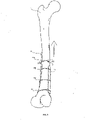
- Figs. 1 and 2 depict a femur 1 with a bone plate and cabling system 10 attached thereto.
- System 10 includes a first bone plate 12 and a second bone plate 14 (best shown in Fig. 2 ).
- Bone plate 12 is standard bone with a plurality of bone plate holes 16 that are shown both as exhibiting circular and elongate forms. Of course, the holes may exhibit any shape or construct known in the art, including, without limitation, oblong compression holes, threaded holes and holes that include deformable structures. Likewise, any number of holes may be provided on plate 12 in connection with the present invention.
- plate 12 includes at least one channel or slot 18 that is sized and shaped to accept and retain a cable of the type discussed more fully below. As shown, plate 12 is designed for use in connection with a distal femur, but can exhibit many different configurations depending upon the bone that requires repair.
- bone plate 14 is shown constructed of porous material, with no holes formed therethrough.
- the porous material is preferably designed to allow for bone to grow directly into plate 14 after implantation.
- plate 14 can be only partially formed of the porous material.
- bone plate 14 may include an underside surface that is of a porous construction, so that when placed against the bone it can facilitate bone in-growth from the affected bone into the plate. In such a case, the remainder of the plate can be of a more solid construction.
- the porous metallic construction of bone plate 14 was created utilizing a laser remelting process ("LRM").
- LRM laser remelting process
- LRM processes disclosed in U.S. Patent Nos. 7,537,664 and 8,147,861 ; U.S. Patent Application Publications Nos. 2006/0147332 , 2007/0142914 , 2008/0004709 ; and U.S. Patent Application Serial Nos. 13/441,154 and 13/618,218 can be utilized. It is also contemplated to form any porous surface via a laser etching procedure.
- a cabling system that includes plurality of cables 20a-d and at least one cannulated screw 22. As shown, the cables may be situated so as to extend through screw 22 and around plate 12 and the femur (cable 20a), around both plates 12 and 14 (cables 20b and 20d) and through channel or slot 18 and around plate 14 (cable 20c).
- the cables may be situated so as to extend through screw 22 and around plate 12 and the femur (cable 20a), around both plates 12 and 14 (cables 20b and 20d) and through channel or slot 18 and around plate 14 (cable 20c).
- the cables may be situated so as to extend through screw 22 and around plate 12 and the femur (cable 20a), around both plates 12 and 14 (cables 20b and 20d) and through channel or slot 18 and around plate 14 (cable 20c).
- other configurations are also contemplated depending upon the bone being repaired and the plates being utilized.
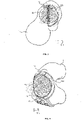
- Screw 22 not only allows for the fixation of plate 12 to the bone, but also its cannula-tion allows for passage of cable 20a therethrough so that the cable only needs to wrap around the affected bone on one side thereof. This is further shown in the cross sectional view of Fig. 3 .
- screw 22 is shown as a one piece screw, it is contemplated that the screw can include a modular head or the like.
- one or more of plate holes 16 to be designed such that they are not only sized and shaped to receive the screws, but also allow polyaxial movement of the screws with respect to the plate.
- Above-mentioned channel or slot 18 is sized, shaped and oriented to receive and guide a cable placed therethrough.
- the channel or slot 18 can be of an open or closed design, the latter of which entirely retains the cable therein.
- any number of them may be provided on a given plate.
- a surgeon will place plate 12 against an affected bone (such as femur 1), so that different portions of the plate span any fracture(s) in the bone. Thereafter screws, such as screws 22, may be placed through the plate and into the bone. Cables 20a-d may then be applied to the construct and plate 14 may be introduced to the opposite side of the bone from plate 12. It is also contemplated to place plate 14 in other positions than directly opposite to plate 12 ( e.g., to the side of the bone). Upon tightening of the cables, plates 12 and 14 are fixed in position.
- plate 14 In situations in which bone plates 12 and 14 are utilized, the use of two plates allows for a stable fixation of the bone fracture via plate 12, while bone is allowed to grow into plate 14. After proper bone growth, a surgeon may elect to remove bone plate 12 from the fracture site, thereby leaving what is effectively become a continuous bone/plate 14 construct. It is, of course, contemplated that the plates may be placed on many different portions of the bone, as well as to leave both plates in place for an extended period of time. Additionally, it is contemplated to utilize only plate 14 with one or more cables at least initially holding it in place. After proper bone growth into plate 14, the cables may be removed. It is to be understood that plate 14 could also be designed to work in conjunction with screws, like screw 22, or to include one or more channels or slots like are discussed above.
- Any holes provided in plates 12 or 14 could also accept a cable plug, which can provide an additional mechanism for associating the plate with a cable.
- a cable plug which can provide an additional mechanism for associating the plate with a cable.
Landscapes
- Health & Medical Sciences (AREA)
- Orthopedic Medicine & Surgery (AREA)
- Surgery (AREA)
- Life Sciences & Earth Sciences (AREA)
- Heart & Thoracic Surgery (AREA)
- Nuclear Medicine, Radiotherapy & Molecular Imaging (AREA)
- Engineering & Computer Science (AREA)
- Biomedical Technology (AREA)
- Neurology (AREA)
- Medical Informatics (AREA)
- Molecular Biology (AREA)
- Animal Behavior & Ethology (AREA)
- General Health & Medical Sciences (AREA)
- Public Health (AREA)
- Veterinary Medicine (AREA)
- Surgical Instruments (AREA)
- Prostheses (AREA)
Description
- The present application claims the benefit of
U.S. provisional patent application No. 62/083,491 filed November 24, 2014 - The present invention pertains to orthopedic bone plates, and in particular, orthopedic bone plates with bone in-growth capabilities.
- A common method utilized in repairing fractures of bones includes affixing bone plates to the bone with screws. Generally, the plates are oriented so that portions thereof are placed on either side of the fracture and screws are placed through at least one bone screw hole of each bone plate portion. Depending upon the particular anatomical area of the fracture, different plate designs exist. For instance, plates designed for use on the distal and proximal portions of long bones such as the femur or tibia may include a shaft and a head, with screw holes extending through each.
- One issue that is often faced by surgeons is the tendency of bone screws inserted through bone plates to back out of the bone plate and/or bone after implantation. Many different bone plate configurations have been designed to prevent such occurrences. For instance, it has been known for some time to thread portions of the bone screws to the plate holes to prevent the unwanted back out. Likewise, different secondary fixation elements (e.g., caps or the like) have been utilized in prior art plates.
- Another issue faced by surgeons is often encountered in repairing perio-prosthetic fractures, which are fractures that occur around an implanted prosthesis (e.g., those utilized in total hip, total knee, or total shoulder arthroplasty). Because of the already implanted prosthesis, and the tendency of the fractures to be somewhat complicated, perio-prosthetic fractures are typically complex and difficult to treat with conventional methods. For instance, in placing screws through a bone plate, it can be difficult for a surgeon to both navigate around the already implanted prosthesis and capture each of the bone fragments of the fracture.
- Therefore, there exists a need for a bone plate and cabling system capable of treating fractures such as perio-prosthetic fractures, as well as providing an alternative to bone screws which have a tendency to back out.
- Document
WO 92/0046 -
JP H07 116241 A - CHANDLER H P ET AL: "THE ROLE OF ALLOGRAFTS IN THE TREATMENT OF PERIPROSTHETIC FEMORAL FRACTURES", JOURNAL OF BONE AND JOINT SURGERY. AMERICAN VOLUME, JOURNAL OF BONE ANO JOINT SURGERY, US, vol. 79A, no. 9, 1 September 1997 (1997-09-01), pages 1422-1432, discloses techniques for treatment of a proximal femoral fracture. In particular, supracondylar fractures are fixed with a lateral blade-plate and a medial allograft strut. Cables or
number 16 wires are used in the area of the stem and screws are used elsewhere for stabilizing the plate and the strut. - A first aspect of the present invention is a bone plate assembly for fixing a fracture of a bone. The bone plate assembly includes a first bone plate attached to the bone and a second bone plate attached to the bone. The second bone plate includes a porous bone in-growth surface and no holes formed therethrough.
- In one embodiment of the first aspect the first and second bone plates are attached to opposite sides of the bone. The assembly further includes at least one screw extending through the first bone plate and into the bone and at least one cable extending around the first and second plates. The at least one screw is cannulated and the at least one cable extends therethrough. The first plate may include a channel or slot and the at least one cable may extend through the channel or slot. The second bone plate may be entirely porous, or the bone in-growth surface may be attached to a solid portion. The first and second plates may be metallic, polymeric or any other suitable material.
- A method of fixing a fracture of a bone not being part of the claimed invention includes the steps of attaching a first plate to the bone so that the first plate spans at least a portion of the fracture, attaching a second plate to the bone so that the second plate spans at least a portion of the fracture and allowing bone to grow into at least a portion of the second plate.
- The method may further include the step of removing the first plate subsequent to the allowing step. The second plate may include a porous bone in-growth surface. The attaching the first plate step may include inserting at least one bone screw through the first plate and into the bone. The attaching steps may include wrapping at least one cable around the first and second plates. The cable may be placed through the at least one screw, a channel or slot or a cable plug.
- A more complete appreciation of the subject matter of the present invention and of the various advantages thereof can be realized by reference of the following detailed description in which references made to the accompanying drawings in which:
-
Fig. 1 is a perspective view of a bone plate and cabling system according to one embodiment of the present invention attached to a femur. -
Fig. 2 is another perspective view of the bone plate and cabling construct ofFig. 1 focusing on a different plate of the construct. -
Fig. 3 is a cross sectional view taken along line D-D ofFig. 2 . -
Fig. 4 is a cross sectional view taken along line B-B ofFig. 1 . - The present invention addresses both above-noted needs, by providing a bone plate and cabling system that does not rely solely upon bone screws inserted through the plate. Rather, the present invention makes use of porous plates that can be initially affixed via a novel cabling system and thereafter allow for bone ingrowth into the plates to support the construct. Although the porous bone plates disclosed herein are described as being constructed of porous metal foam, it is contemplated that the bone plates may be of many different types of materials, including, but limited, ceramics, plastics or the like. It is also contemplated to utilize the porous bone plates of the present invention in conjunction with more standard bone plates known in the art.
-
Figs. 1 and2 depict afemur 1 with a bone plate andcabling system 10 attached thereto.System 10, as shown, includes afirst bone plate 12 and a second bone plate 14 (best shown inFig. 2 ).Bone plate 12 is standard bone with a plurality ofbone plate holes 16 that are shown both as exhibiting circular and elongate forms. Of course, the holes may exhibit any shape or construct known in the art, including, without limitation, oblong compression holes, threaded holes and holes that include deformable structures. Likewise, any number of holes may be provided onplate 12 in connection with the present invention. Additionally,plate 12 includes at least one channel orslot 18 that is sized and shaped to accept and retain a cable of the type discussed more fully below. As shown,plate 12 is designed for use in connection with a distal femur, but can exhibit many different configurations depending upon the bone that requires repair. - On the other hand,
bone plate 14 is shown constructed of porous material, with no holes formed therethrough. The porous material is preferably designed to allow for bone to grow directly intoplate 14 after implantation. Although shown as consisting largely of the porous material,plate 14 can be only partially formed of the porous material. Specifically, in other embodiments,bone plate 14 may include an underside surface that is of a porous construction, so that when placed against the bone it can facilitate bone in-growth from the affected bone into the plate. In such a case, the remainder of the plate can be of a more solid construction. - As shown, the porous metallic construction of
bone plate 14 was created utilizing a laser remelting process ("LRM"). In fact, it is contemplated to form the entirety ofplate 14 with such a process, including any solid portions that may be included therein. Those solid portions could alternatively be formed through more conventional processes (e.g., molding, forging, etc...) and a porous lower or bone contacting surface can be later affixed thereto via a process like LRM. Without limitation, the LRM processes disclosed inU.S. Patent Nos. 7,537,664 and8,147,861 ;U.S. Patent Application Publications Nos. 2006/0147332 ,2007/0142914 ,2008/0004709 ; andU.S. Patent Application Serial Nos. 13/441,154 and13/618,218 - Also depicted in
Figs. 1 and2 is a cabling system that includes plurality ofcables 20a-d and at least one cannulatedscrew 22. As shown, the cables may be situated so as to extend throughscrew 22 and aroundplate 12 and the femur (cable 20a), around bothplates 12 and 14 (cables slot 18 and around plate 14 (cable 20c). Of course, other configurations are also contemplated depending upon the bone being repaired and the plates being utilized. -
Screw 22 not only allows for the fixation ofplate 12 to the bone, but also its cannula-tion allows for passage ofcable 20a therethrough so that the cable only needs to wrap around the affected bone on one side thereof. This is further shown in the cross sectional view ofFig. 3 . Althoughscrew 22 is shown as a one piece screw, it is contemplated that the screw can include a modular head or the like. In addition, it is contemplated for one or more of plate holes 16 to be designed such that they are not only sized and shaped to receive the screws, but also allow polyaxial movement of the screws with respect to the plate. Above-mentioned channel orslot 18 is sized, shaped and oriented to receive and guide a cable placed therethrough. The channel orslot 18 can be of an open or closed design, the latter of which entirely retains the cable therein. Of course, although only a single channel or slot is shown included onplate 12, any number of them may be provided on a given plate. - In use, a surgeon will place
plate 12 against an affected bone (such as femur 1), so that different portions of the plate span any fracture(s) in the bone. Thereafter screws, such asscrews 22, may be placed through the plate and into the bone.Cables 20a-d may then be applied to the construct andplate 14 may be introduced to the opposite side of the bone fromplate 12. It is also contemplated to placeplate 14 in other positions than directly opposite to plate 12 (e.g., to the side of the bone). Upon tightening of the cables,plates - In the case of a peri-prosthetic fracture, care must be taken as to the placement of any screws so as not to interfere with the already implanted prosthesis. However, it is possible through the use of the plates, screws and cables of the present invention properly stabilize the fracture without the need for screws extending into each bone fragment. Rather, less screws can be utilized when utilizing cables 26. The cables act to stabilize the fracture, much like multiple screws would in the case of a standard bone plate use. This is especially true in the context of peri-prosthetic fractures, where the amount of bone screws that can be utilized is limited.
- In situations in which
bone plates plate 12, while bone is allowed to grow intoplate 14. After proper bone growth, a surgeon may elect to removebone plate 12 from the fracture site, thereby leaving what is effectively become a continuous bone/plate 14 construct. It is, of course, contemplated that the plates may be placed on many different portions of the bone, as well as to leave both plates in place for an extended period of time. Additionally, it is contemplated to utilize only plate 14 with one or more cables at least initially holding it in place. After proper bone growth intoplate 14, the cables may be removed. It is to be understood thatplate 14 could also be designed to work in conjunction with screws, likescrew 22, or to include one or more channels or slots like are discussed above. Any holes provided inplates plates U.S. Patent No. 8,142,434 ,U.S. Patent Application Publication No. 2014/0107710 andU.S. Provisional Application No. 62/035,074 - Although the invention herein has been described with reference to particular embodiments, it is to be understood that these embodiments are merely illustrative of the principles and applications of the present invention.
Claims (9)
- A bone plate assembly for fixing a fracture of a bone (1) comprising:a first bone plate (12) adapted to be attached to the bone (1);a second bone plate (14) adapted to be attached to the bone (1), the second bone plate (14) including a porous bone in-growth surface and no holes formed therethrough; andat least one screw (22) extending through the first bone plate (12) and into the bone (1) and at least one cable (20a-d) extending around the first and second plates (12, 14);characterized in that the at least one screw (22) is cannulated and the at least one cable (20a-d) extends therethrough.
- The bone plate assembly of claim 1, wherein the first and second bone plates (12, 14) are adapted to be attached to opposite sides of the bone (1).
- The bone plate assembly of any preceding claim, wherein the first plate (12) includes a channel or slot (18) and the at least one cable (20a-d) extends through the channel or slot (18).
- The bone plate assembly of any of the preceding claims, wherein the second bone plate (14) is entirely porous.
- The bone plate assembly of any of the preceding claims, wherein the bone in-growth surface is attached to a solid portion.
- The bone plate assembly of any of the preceding claims, wherein the first and second plates (12, 14) are metallic.
- The bone plate assembly of any of the preceding claims, further comprising a plurality of screws (22) and cables (20a-d).
- The bone plate assembly of claim 7, wherein the first plate (12) includes a plurality of channels or slots (18) and the plurality of cables (20a-d) extend through the channels or slots (18).
- The bone plate assembly of any of the preceding claims, wherein the first plate (12) is removable subsequent to bone growing into the second plate (14).
Applications Claiming Priority (1)
| Application Number | Priority Date | Filing Date | Title |
|---|---|---|---|
| US201462083491P | 2014-11-24 | 2014-11-24 |
Publications (2)
| Publication Number | Publication Date |
|---|---|
| EP3023067A1 EP3023067A1 (en) | 2016-05-25 |
| EP3023067B1 true EP3023067B1 (en) | 2022-11-23 |
Family
ID=54704954
Family Applications (1)
| Application Number | Title | Priority Date | Filing Date |
|---|---|---|---|
| EP15003353.8A Active EP3023067B1 (en) | 2014-11-24 | 2015-11-24 | Strut plate and cabling system |
Country Status (2)
| Country | Link |
|---|---|
| US (2) | US20160143663A1 (en) |
| EP (1) | EP3023067B1 (en) |
Families Citing this family (5)
| Publication number | Priority date | Publication date | Assignee | Title |
|---|---|---|---|---|
| EP3184064B1 (en) * | 2015-12-23 | 2019-05-01 | Stryker European Holdings I, LLC | Bone plate with guiding channels |
| EP3522802B1 (en) * | 2016-10-07 | 2024-10-23 | Acumed LLC | System for bone fixation using a plate straddled by a retainer |
| US11337761B2 (en) | 2019-02-07 | 2022-05-24 | Stryker European Operations Limited | Surgical systems and methods for facilitating tissue treatment |
| US11395686B2 (en) | 2020-04-20 | 2022-07-26 | Khay-Yong Saw | Bone fixation plate and method of using thereof |
| US11608050B1 (en) | 2021-08-13 | 2023-03-21 | Oshkosh Defense, Llc | Electrified military vehicle |
Citations (3)
| Publication number | Priority date | Publication date | Assignee | Title |
|---|---|---|---|---|
| US4743256A (en) * | 1985-10-04 | 1988-05-10 | Brantigan John W | Surgical prosthetic implant facilitating vertebral interbody fusion and method |
| WO2006065774A1 (en) * | 2004-12-13 | 2006-06-22 | St. Francis Medical Technologies, Inc. | Inter-facet implant |
| US20080269893A1 (en) * | 2007-04-25 | 2008-10-30 | Jmea Corporation | Prosthesis with a Selectively Applied Bone Growth Promoting Agent |
Family Cites Families (26)
| Publication number | Priority date | Publication date | Assignee | Title |
|---|---|---|---|---|
| US3900025A (en) * | 1974-04-24 | 1975-08-19 | Jr Walter P Barnes | Apparatus for distracting or compressing longitudinal bone segments |
| US5108432A (en) * | 1990-06-24 | 1992-04-28 | Pfizer Hospital Products Group, Inc. | Porous fixation surface |
| GB9206018D0 (en) * | 1992-03-19 | 1992-04-29 | Dall Desmond Meiring | Bone fixation system |
| JP3389316B2 (en) * | 1993-08-31 | 2003-03-24 | 京セラ株式会社 | Absorbable biomaterial and method for producing the same |
| US5702399A (en) * | 1996-05-16 | 1997-12-30 | Pioneer Laboratories, Inc. | Surgical cable screw connector |
| US5810824A (en) * | 1997-02-13 | 1998-09-22 | Chan; Kwan-Ho | Surgical fastener assembly and method for bone fracture fixation |
| US5993452A (en) * | 1998-08-24 | 1999-11-30 | Biomet Inc. | Cerclage system |
| US20030135212A1 (en) * | 2002-01-11 | 2003-07-17 | Y. Chow James C. | Rod and plate bone fixation device for persons with osteophorosis |
| US20060147332A1 (en) | 2004-12-30 | 2006-07-06 | Howmedica Osteonics Corp. | Laser-produced porous structure |
| DE60300277T2 (en) | 2002-11-08 | 2006-01-12 | Howmedica Osteonics Corp. | Laser generated porous surface |
| EP1464295A3 (en) * | 2003-04-01 | 2006-04-26 | Zimmer GmbH | Implant |
| CA2546050C (en) * | 2003-11-18 | 2012-08-28 | Synthes Gmbh | Osteosynthesis plate set |
| US7704252B2 (en) * | 2004-04-21 | 2010-04-27 | Synthes Usa, Llc | Sternal reconstruction system |
| US9055984B2 (en) * | 2004-04-21 | 2015-06-16 | DePuy Synthes Products, Inc. | Sternal reconstruction system |
| DE202005019277U1 (en) | 2005-10-14 | 2006-02-02 | Stryker Leibinger Gmbh & Co. Kg | Bone plate for adjustable securing broken bone together for healing has two or more holes (16) lengthened along the long axis of the plate and two or more holes lengthed at right angles to theplate long axis |
| US8728387B2 (en) | 2005-12-06 | 2014-05-20 | Howmedica Osteonics Corp. | Laser-produced porous surface |
| EP1803513B1 (en) | 2005-12-30 | 2017-03-29 | Howmedica Osteonics Corp. | Method of manufacturing implants using laser |
| US8147861B2 (en) | 2006-08-15 | 2012-04-03 | Howmedica Osteonics Corp. | Antimicrobial implant |
| US8142434B2 (en) | 2007-10-17 | 2012-03-27 | Stryker Trauma Gmbh | Cam-locking of cable for fracture plate |
| US8343155B2 (en) * | 2008-05-15 | 2013-01-01 | Zimmer, Inc. | Cable button |
| US20100211113A1 (en) * | 2009-02-17 | 2010-08-19 | Jon Olson | Bone Screw With Channels |
| US9277912B2 (en) * | 2011-06-14 | 2016-03-08 | University Of South Florida | Systems and methods for ankle syndesmosis fixation |
| US9320553B2 (en) * | 2011-10-18 | 2016-04-26 | Biomet Manufacturing, Llc | Compressive distal humerus plating system |
| US9135374B2 (en) | 2012-04-06 | 2015-09-15 | Howmedica Osteonics Corp. | Surface modified unit cell lattice structures for optimized secure freeform fabrication |
| US9180010B2 (en) | 2012-04-06 | 2015-11-10 | Howmedica Osteonics Corp. | Surface modified unit cell lattice structures for optimized secure freeform fabrication |
| US9101426B2 (en) | 2012-10-11 | 2015-08-11 | Stryker Trauma Sa | Cable plug |
-
2015
- 2015-11-23 US US14/949,185 patent/US20160143663A1/en not_active Abandoned
- 2015-11-24 EP EP15003353.8A patent/EP3023067B1/en active Active
-
2020
- 2020-04-10 US US16/845,330 patent/US11457954B2/en active Active
Patent Citations (3)
| Publication number | Priority date | Publication date | Assignee | Title |
|---|---|---|---|---|
| US4743256A (en) * | 1985-10-04 | 1988-05-10 | Brantigan John W | Surgical prosthetic implant facilitating vertebral interbody fusion and method |
| WO2006065774A1 (en) * | 2004-12-13 | 2006-06-22 | St. Francis Medical Technologies, Inc. | Inter-facet implant |
| US20080269893A1 (en) * | 2007-04-25 | 2008-10-30 | Jmea Corporation | Prosthesis with a Selectively Applied Bone Growth Promoting Agent |
Non-Patent Citations (1)
| Title |
|---|
| CHANDLER H P ET AL: "THE ROLE OF ALLOGRAFTS IN THE TREATMENT OF PERIPROSTHETIC FEMORAL FRACTURES", JOURNAL OF BONE AND JOINT SURGERY. AMERICAN VOLUME, JOURNAL OF BONE AND JOINT SURGERY, US, vol. 79A, no. 9, 1 September 1997 (1997-09-01), pages 1422 - 1432, XP000702072, ISSN: 0021-9355 * |
Also Published As
| Publication number | Publication date |
|---|---|
| US20200237407A1 (en) | 2020-07-30 |
| US11457954B2 (en) | 2022-10-04 |
| US20160143663A1 (en) | 2016-05-26 |
| EP3023067A1 (en) | 2016-05-25 |
Similar Documents
| Publication | Publication Date | Title |
|---|---|---|
| EP2777637B1 (en) | Instruments for use in disassembling implants | |
| US11457954B2 (en) | Strut plate and cabling system | |
| US9707080B2 (en) | Removable augment for medical implant | |
| EP2498723B1 (en) | Spinal implant configured for lateral insertion | |
| RU2461365C2 (en) | Instruments for joint surgery | |
| EP3906898B1 (en) | Instruments for midline insertion of spinal implant | |
| US8343200B2 (en) | Orthopedic screw system | |
| US7192448B2 (en) | Arthroplasty devices with resorbable component | |
| EP2173268B1 (en) | Devices for stabilizing bone compatible for use with bone screws | |
| EP3062718B1 (en) | Osteotomy implant | |
| WO2014026007A1 (en) | Expandable tlif/plif cage assemblies and methods | |
| US20100249842A1 (en) | Spinous process cross-link | |
| WO2009052252A2 (en) | Fibular stiffener and bony defect replacer | |
| CA3019352A1 (en) | Arthrodesis devices for generating and applying compression within joints | |
| US10149763B2 (en) | Multipurpose void filling prosthesis | |
| EP2777621B1 (en) | Assembling an orthopaedic prosthesis | |
| WO2007112123A2 (en) | Apparatus and method for the treatment of periprosthetic fractures | |
| JP7539861B2 (en) | Arthroplasty implant system for creating and applying dynamic compression - Patents.com | |
| WO2020097613A3 (en) | Intervertebral spinal implant and surgical methods | |
| US10582957B2 (en) | Bone fixation implant and means of fixation | |
| US20100063590A1 (en) | Laminoplasty implant | |
| EP2777625B1 (en) | Prosthetic component | |
| US20160113645A1 (en) | Implant with suture anchor fixation capability | |
| EP2937051A1 (en) | Implant for tibial plateau leveling osteotomy fixation | |
| RU2425651C2 (en) | Method for initial stabilisation of acetabular component at hip replacement |
Legal Events
| Date | Code | Title | Description |
|---|---|---|---|
| AK | Designated contracting states |
Kind code of ref document: A1 Designated state(s): AL AT BE BG CH CY CZ DE DK EE ES FI FR GB GR HR HU IE IS IT LI LT LU LV MC MK MT NL NO PL PT RO RS SE SI SK SM TR |
|
| AX | Request for extension of the european patent |
Extension state: BA ME |
|
| PUAI | Public reference made under article 153(3) epc to a published international application that has entered the european phase |
Free format text: ORIGINAL CODE: 0009012 |
|
| STAA | Information on the status of an ep patent application or granted ep patent |
Free format text: STATUS: REQUEST FOR EXAMINATION WAS MADE |
|
| 17P | Request for examination filed |
Effective date: 20161107 |
|
| STAA | Information on the status of an ep patent application or granted ep patent |
Free format text: STATUS: EXAMINATION IS IN PROGRESS |
|
| 17Q | First examination report despatched |
Effective date: 20191219 |
|
| RAP1 | Party data changed (applicant data changed or rights of an application transferred) |
Owner name: STRYKER EUROPEAN OPERATIONS HOLDINGS LLC |
|
| GRAP | Despatch of communication of intention to grant a patent |
Free format text: ORIGINAL CODE: EPIDOSNIGR1 |
|
| STAA | Information on the status of an ep patent application or granted ep patent |
Free format text: STATUS: GRANT OF PATENT IS INTENDED |
|
| INTG | Intention to grant announced |
Effective date: 20220623 |
|
| GRAS | Grant fee paid |
Free format text: ORIGINAL CODE: EPIDOSNIGR3 |
|
| GRAA | (expected) grant |
Free format text: ORIGINAL CODE: 0009210 |
|
| STAA | Information on the status of an ep patent application or granted ep patent |
Free format text: STATUS: THE PATENT HAS BEEN GRANTED |
|
| AK | Designated contracting states |
Kind code of ref document: B1 Designated state(s): AL AT BE BG CH CY CZ DE DK EE ES FI FR GB GR HR HU IE IS IT LI LT LU LV MC MK MT NL NO PL PT RO RS SE SI SK SM TR |
|
| REG | Reference to a national code |
Ref country code: GB Ref legal event code: FG4D |
|
| REG | Reference to a national code |
Ref country code: CH Ref legal event code: EP |
|
| REG | Reference to a national code |
Ref country code: AT Ref legal event code: REF Ref document number: 1532670 Country of ref document: AT Kind code of ref document: T Effective date: 20221215 Ref country code: DE Ref legal event code: R096 Ref document number: 602015081659 Country of ref document: DE |
|
| REG | Reference to a national code |
Ref country code: IE Ref legal event code: FG4D |
|
| REG | Reference to a national code |
Ref country code: LT Ref legal event code: MG9D |
|
| REG | Reference to a national code |
Ref country code: NL Ref legal event code: MP Effective date: 20221123 |
|
| REG | Reference to a national code |
Ref country code: AT Ref legal event code: MK05 Ref document number: 1532670 Country of ref document: AT Kind code of ref document: T Effective date: 20221123 |
|
| PG25 | Lapsed in a contracting state [announced via postgrant information from national office to epo] |
Ref country code: SE Free format text: LAPSE BECAUSE OF FAILURE TO SUBMIT A TRANSLATION OF THE DESCRIPTION OR TO PAY THE FEE WITHIN THE PRESCRIBED TIME-LIMIT Effective date: 20221123 Ref country code: PT Free format text: LAPSE BECAUSE OF FAILURE TO SUBMIT A TRANSLATION OF THE DESCRIPTION OR TO PAY THE FEE WITHIN THE PRESCRIBED TIME-LIMIT Effective date: 20230323 Ref country code: NO Free format text: LAPSE BECAUSE OF FAILURE TO SUBMIT A TRANSLATION OF THE DESCRIPTION OR TO PAY THE FEE WITHIN THE PRESCRIBED TIME-LIMIT Effective date: 20230223 Ref country code: LT Free format text: LAPSE BECAUSE OF FAILURE TO SUBMIT A TRANSLATION OF THE DESCRIPTION OR TO PAY THE FEE WITHIN THE PRESCRIBED TIME-LIMIT Effective date: 20221123 Ref country code: FI Free format text: LAPSE BECAUSE OF FAILURE TO SUBMIT A TRANSLATION OF THE DESCRIPTION OR TO PAY THE FEE WITHIN THE PRESCRIBED TIME-LIMIT Effective date: 20221123 Ref country code: ES Free format text: LAPSE BECAUSE OF FAILURE TO SUBMIT A TRANSLATION OF THE DESCRIPTION OR TO PAY THE FEE WITHIN THE PRESCRIBED TIME-LIMIT Effective date: 20221123 Ref country code: AT Free format text: LAPSE BECAUSE OF FAILURE TO SUBMIT A TRANSLATION OF THE DESCRIPTION OR TO PAY THE FEE WITHIN THE PRESCRIBED TIME-LIMIT Effective date: 20221123 |
|
| PG25 | Lapsed in a contracting state [announced via postgrant information from national office to epo] |
Ref country code: RS Free format text: LAPSE BECAUSE OF FAILURE TO SUBMIT A TRANSLATION OF THE DESCRIPTION OR TO PAY THE FEE WITHIN THE PRESCRIBED TIME-LIMIT Effective date: 20221123 Ref country code: PL Free format text: LAPSE BECAUSE OF FAILURE TO SUBMIT A TRANSLATION OF THE DESCRIPTION OR TO PAY THE FEE WITHIN THE PRESCRIBED TIME-LIMIT Effective date: 20221123 Ref country code: LV Free format text: LAPSE BECAUSE OF FAILURE TO SUBMIT A TRANSLATION OF THE DESCRIPTION OR TO PAY THE FEE WITHIN THE PRESCRIBED TIME-LIMIT Effective date: 20221123 Ref country code: IS Free format text: LAPSE BECAUSE OF FAILURE TO SUBMIT A TRANSLATION OF THE DESCRIPTION OR TO PAY THE FEE WITHIN THE PRESCRIBED TIME-LIMIT Effective date: 20230323 Ref country code: HR Free format text: LAPSE BECAUSE OF FAILURE TO SUBMIT A TRANSLATION OF THE DESCRIPTION OR TO PAY THE FEE WITHIN THE PRESCRIBED TIME-LIMIT Effective date: 20221123 Ref country code: GR Free format text: LAPSE BECAUSE OF FAILURE TO SUBMIT A TRANSLATION OF THE DESCRIPTION OR TO PAY THE FEE WITHIN THE PRESCRIBED TIME-LIMIT Effective date: 20230224 |
|
| P01 | Opt-out of the competence of the unified patent court (upc) registered |
Effective date: 20230522 |
|
| PG25 | Lapsed in a contracting state [announced via postgrant information from national office to epo] |
Ref country code: NL Free format text: LAPSE BECAUSE OF FAILURE TO SUBMIT A TRANSLATION OF THE DESCRIPTION OR TO PAY THE FEE WITHIN THE PRESCRIBED TIME-LIMIT Effective date: 20221123 |
|
| REG | Reference to a national code |
Ref country code: BE Ref legal event code: MM Effective date: 20221130 |
|
| PG25 | Lapsed in a contracting state [announced via postgrant information from national office to epo] |
Ref country code: SM Free format text: LAPSE BECAUSE OF FAILURE TO SUBMIT A TRANSLATION OF THE DESCRIPTION OR TO PAY THE FEE WITHIN THE PRESCRIBED TIME-LIMIT Effective date: 20221123 Ref country code: RO Free format text: LAPSE BECAUSE OF FAILURE TO SUBMIT A TRANSLATION OF THE DESCRIPTION OR TO PAY THE FEE WITHIN THE PRESCRIBED TIME-LIMIT Effective date: 20221123 Ref country code: EE Free format text: LAPSE BECAUSE OF FAILURE TO SUBMIT A TRANSLATION OF THE DESCRIPTION OR TO PAY THE FEE WITHIN THE PRESCRIBED TIME-LIMIT Effective date: 20221123 Ref country code: DK Free format text: LAPSE BECAUSE OF FAILURE TO SUBMIT A TRANSLATION OF THE DESCRIPTION OR TO PAY THE FEE WITHIN THE PRESCRIBED TIME-LIMIT Effective date: 20221123 Ref country code: CZ Free format text: LAPSE BECAUSE OF FAILURE TO SUBMIT A TRANSLATION OF THE DESCRIPTION OR TO PAY THE FEE WITHIN THE PRESCRIBED TIME-LIMIT Effective date: 20221123 |
|
| REG | Reference to a national code |
Ref country code: DE Ref legal event code: R097 Ref document number: 602015081659 Country of ref document: DE |
|
| PG25 | Lapsed in a contracting state [announced via postgrant information from national office to epo] |
Ref country code: SK Free format text: LAPSE BECAUSE OF FAILURE TO SUBMIT A TRANSLATION OF THE DESCRIPTION OR TO PAY THE FEE WITHIN THE PRESCRIBED TIME-LIMIT Effective date: 20221123 Ref country code: LU Free format text: LAPSE BECAUSE OF NON-PAYMENT OF DUE FEES Effective date: 20221124 Ref country code: AL Free format text: LAPSE BECAUSE OF FAILURE TO SUBMIT A TRANSLATION OF THE DESCRIPTION OR TO PAY THE FEE WITHIN THE PRESCRIBED TIME-LIMIT Effective date: 20221123 |
|
| PLBE | No opposition filed within time limit |
Free format text: ORIGINAL CODE: 0009261 |
|
| STAA | Information on the status of an ep patent application or granted ep patent |
Free format text: STATUS: NO OPPOSITION FILED WITHIN TIME LIMIT |
|
| PG25 | Lapsed in a contracting state [announced via postgrant information from national office to epo] |
Ref country code: IE Free format text: LAPSE BECAUSE OF NON-PAYMENT OF DUE FEES Effective date: 20221124 |
|
| 26N | No opposition filed |
Effective date: 20230824 |
|
| PG25 | Lapsed in a contracting state [announced via postgrant information from national office to epo] |
Ref country code: SI Free format text: LAPSE BECAUSE OF FAILURE TO SUBMIT A TRANSLATION OF THE DESCRIPTION OR TO PAY THE FEE WITHIN THE PRESCRIBED TIME-LIMIT Effective date: 20221123 Ref country code: BE Free format text: LAPSE BECAUSE OF NON-PAYMENT OF DUE FEES Effective date: 20221130 |
|
| PG25 | Lapsed in a contracting state [announced via postgrant information from national office to epo] |
Ref country code: HU Free format text: LAPSE BECAUSE OF FAILURE TO SUBMIT A TRANSLATION OF THE DESCRIPTION OR TO PAY THE FEE WITHIN THE PRESCRIBED TIME-LIMIT; INVALID AB INITIO Effective date: 20151124 |
|
| PG25 | Lapsed in a contracting state [announced via postgrant information from national office to epo] |
Ref country code: CY Free format text: LAPSE BECAUSE OF FAILURE TO SUBMIT A TRANSLATION OF THE DESCRIPTION OR TO PAY THE FEE WITHIN THE PRESCRIBED TIME-LIMIT Effective date: 20221123 |
|
| PG25 | Lapsed in a contracting state [announced via postgrant information from national office to epo] |
Ref country code: MK Free format text: LAPSE BECAUSE OF FAILURE TO SUBMIT A TRANSLATION OF THE DESCRIPTION OR TO PAY THE FEE WITHIN THE PRESCRIBED TIME-LIMIT Effective date: 20221123 Ref country code: IT Free format text: LAPSE BECAUSE OF FAILURE TO SUBMIT A TRANSLATION OF THE DESCRIPTION OR TO PAY THE FEE WITHIN THE PRESCRIBED TIME-LIMIT Effective date: 20221123 |
|
| PG25 | Lapsed in a contracting state [announced via postgrant information from national office to epo] |
Ref country code: MC Free format text: LAPSE BECAUSE OF FAILURE TO SUBMIT A TRANSLATION OF THE DESCRIPTION OR TO PAY THE FEE WITHIN THE PRESCRIBED TIME-LIMIT Effective date: 20221123 |
|
| PG25 | Lapsed in a contracting state [announced via postgrant information from national office to epo] |
Ref country code: MC Free format text: LAPSE BECAUSE OF FAILURE TO SUBMIT A TRANSLATION OF THE DESCRIPTION OR TO PAY THE FEE WITHIN THE PRESCRIBED TIME-LIMIT Effective date: 20221123 |
|
| PG25 | Lapsed in a contracting state [announced via postgrant information from national office to epo] |
Ref country code: BG Free format text: LAPSE BECAUSE OF FAILURE TO SUBMIT A TRANSLATION OF THE DESCRIPTION OR TO PAY THE FEE WITHIN THE PRESCRIBED TIME-LIMIT Effective date: 20221123 |
|
| PG25 | Lapsed in a contracting state [announced via postgrant information from national office to epo] |
Ref country code: MT Free format text: LAPSE BECAUSE OF FAILURE TO SUBMIT A TRANSLATION OF THE DESCRIPTION OR TO PAY THE FEE WITHIN THE PRESCRIBED TIME-LIMIT Effective date: 20221123 |
|
| PGFP | Annual fee paid to national office [announced via postgrant information from national office to epo] |
Ref country code: FR Payment date: 20250930 Year of fee payment: 11 |
|
| REG | Reference to a national code |
Ref country code: CH Ref legal event code: U11 Free format text: ST27 STATUS EVENT CODE: U-0-0-U10-U11 (AS PROVIDED BY THE NATIONAL OFFICE) Effective date: 20251201 |
|
| PG25 | Lapsed in a contracting state [announced via postgrant information from national office to epo] |
Ref country code: TR Free format text: LAPSE BECAUSE OF FAILURE TO SUBMIT A TRANSLATION OF THE DESCRIPTION OR TO PAY THE FEE WITHIN THE PRESCRIBED TIME-LIMIT Effective date: 20221123 |
|
| PGFP | Annual fee paid to national office [announced via postgrant information from national office to epo] |
Ref country code: DE Payment date: 20250930 Year of fee payment: 11 |
|
| PGFP | Annual fee paid to national office [announced via postgrant information from national office to epo] |
Ref country code: GB Payment date: 20251001 Year of fee payment: 11 |
|
| PGFP | Annual fee paid to national office [announced via postgrant information from national office to epo] |
Ref country code: CH Payment date: 20251201 Year of fee payment: 11 |