EP3023030B1 - Tête pour un instrument de soin buccal - Google Patents
Tête pour un instrument de soin buccal Download PDFInfo
- Publication number
- EP3023030B1 EP3023030B1 EP14193799.5A EP14193799A EP3023030B1 EP 3023030 B1 EP3023030 B1 EP 3023030B1 EP 14193799 A EP14193799 A EP 14193799A EP 3023030 B1 EP3023030 B1 EP 3023030B1
- Authority
- EP
- European Patent Office
- Prior art keywords
- row
- head
- filaments
- tufts
- sectional area
- Prior art date
- Legal status (The legal status is an assumption and is not a legal conclusion. Google has not performed a legal analysis and makes no representation as to the accuracy of the status listed.)
- Active
Links
- 238000004140 cleaning Methods 0.000 claims description 45
- 210000003128 head Anatomy 0.000 description 92
- 230000001680 brushing effect Effects 0.000 description 20
- 230000007704 transition Effects 0.000 description 9
- 238000000034 method Methods 0.000 description 8
- 230000008569 process Effects 0.000 description 8
- 238000005452 bending Methods 0.000 description 7
- 230000035515 penetration Effects 0.000 description 6
- 239000000463 material Substances 0.000 description 5
- 230000035807 sensation Effects 0.000 description 5
- 230000009471 action Effects 0.000 description 4
- 230000000694 effects Effects 0.000 description 4
- 210000000214 mouth Anatomy 0.000 description 4
- 230000010363 phase shift Effects 0.000 description 4
- 229920002725 thermoplastic elastomer Polymers 0.000 description 4
- 238000009732 tufting Methods 0.000 description 4
- 239000004677 Nylon Substances 0.000 description 3
- 240000007643 Phytolacca americana Species 0.000 description 3
- 230000015572 biosynthetic process Effects 0.000 description 3
- 238000001746 injection moulding Methods 0.000 description 3
- 229920001778 nylon Polymers 0.000 description 3
- 239000005995 Aluminium silicate Substances 0.000 description 2
- 235000012211 aluminium silicate Nutrition 0.000 description 2
- 239000004927 clay Substances 0.000 description 2
- 238000002474 experimental method Methods 0.000 description 2
- NLYAJNPCOHFWQQ-UHFFFAOYSA-N kaolin Chemical compound O.O.O=[Al]O[Si](=O)O[Si](=O)O[Al]=O NLYAJNPCOHFWQQ-UHFFFAOYSA-N 0.000 description 2
- 230000000149 penetrating effect Effects 0.000 description 2
- 238000005201 scrubbing Methods 0.000 description 2
- 238000012876 topography Methods 0.000 description 2
- 208000003433 Gingival Pocket Diseases 0.000 description 1
- 238000004873 anchoring Methods 0.000 description 1
- 238000000429 assembly Methods 0.000 description 1
- 230000000712 assembly Effects 0.000 description 1
- 230000008859 change Effects 0.000 description 1
- 238000004040 coloring Methods 0.000 description 1
- 239000000356 contaminant Substances 0.000 description 1
- 230000001419 dependent effect Effects 0.000 description 1
- 230000006870 function Effects 0.000 description 1
- 201000005562 gingival recession Diseases 0.000 description 1
- 238000003780 insertion Methods 0.000 description 1
- 230000037431 insertion Effects 0.000 description 1
- 238000004519 manufacturing process Methods 0.000 description 1
- 238000005259 measurement Methods 0.000 description 1
- -1 polybutylene Polymers 0.000 description 1
- 229920001748 polybutylene Polymers 0.000 description 1
- 210000004872 soft tissue Anatomy 0.000 description 1
- 239000000126 substance Substances 0.000 description 1
- 210000004357 third molar Anatomy 0.000 description 1
Images
Classifications
-
- A—HUMAN NECESSITIES
- A46—BRUSHWARE
- A46B—BRUSHES
- A46B9/00—Arrangements of the bristles in the brush body
- A46B9/02—Position or arrangement of bristles in relation to surface of the brush body, e.g. inclined, in rows, in groups
- A46B9/025—Position or arrangement of bristles in relation to surface of the brush body, e.g. inclined, in rows, in groups the bristles or the tufts being arranged in an angled position relative to each other
-
- A—HUMAN NECESSITIES
- A46—BRUSHWARE
- A46B—BRUSHES
- A46B9/00—Arrangements of the bristles in the brush body
- A46B9/02—Position or arrangement of bristles in relation to surface of the brush body, e.g. inclined, in rows, in groups
- A46B9/04—Arranged like in or for toothbrushes
-
- A—HUMAN NECESSITIES
- A46—BRUSHWARE
- A46B—BRUSHES
- A46B9/00—Arrangements of the bristles in the brush body
- A46B9/02—Position or arrangement of bristles in relation to surface of the brush body, e.g. inclined, in rows, in groups
-
- A—HUMAN NECESSITIES
- A46—BRUSHWARE
- A46B—BRUSHES
- A46B15/00—Other brushes; Brushes with additional arrangements
-
- A—HUMAN NECESSITIES
- A46—BRUSHWARE
- A46B—BRUSHES
- A46B15/00—Other brushes; Brushes with additional arrangements
- A46B15/0055—Brushes combined with other articles normally separate from the brushing process, e.g. combs, razors, mirrors
- A46B15/0081—Brushes with a scraper, e.g. tongue scraper
-
- A—HUMAN NECESSITIES
- A46—BRUSHWARE
- A46B—BRUSHES
- A46B9/00—Arrangements of the bristles in the brush body
- A46B9/02—Position or arrangement of bristles in relation to surface of the brush body, e.g. inclined, in rows, in groups
- A46B9/026—Position or arrangement of bristles in relation to surface of the brush body, e.g. inclined, in rows, in groups where the surface of the brush body or carrier is not in one plane, e.g. not flat
-
- A—HUMAN NECESSITIES
- A46—BRUSHWARE
- A46B—BRUSHES
- A46B2200/00—Brushes characterized by their functions, uses or applications
- A46B2200/10—For human or animal care
- A46B2200/1066—Toothbrush for cleaning the teeth or dentures
Definitions
- the present disclosure is concerned with a head for an oral care implement and with such a head comprising at least one row of tufts having an upper top cleaning surface in the form of a continuous wave-shape.
- Tufts composed of a plurality of filaments for oral care implements, like manual and powered toothbrushes are well known in the art.
- the tufts are attached to a mounting surface of a head intended for insertion into a user's oral cavity.
- a grip handle is usually attached to the head, which handle is held by the user during brushing.
- the head is either permanently connected or repeatedly attachable to and detachable from the handle.
- Toothbrushes comprising a plurality of filaments extending in different length extensions with respect to the mounting surface from which they extend are also known in the art.
- a toothbrush having a bristle support head with a plurality of bristles densely implanted thereon.
- a brushing surface is formed by the ends of the bristles which brushing surface is wave-shaped to increase the contact area between the teeth and the brushing surface of the filaments to remove contaminants from interdental spaces more effectively.
- toothbrushes comprising this type of filament assemblies may clean the outer buccal face of teeth adequately, they are not as well suited to provide adequate removal of plaque and debris from the gingival margin, interproximal areas, lingual surfaces and other hard to reach areas of the mouth in a sufficient manner.
- AU2003252861 , US2002004964 and WO9601578 disclose a head for an oral care implement comprising at least a row of tufts with the filaments of different length extensions in the form of a continuous wave-shape.
- the invention is defined by the subject-matter according to the independent claim 1. Further aspects of the invention are set out in the dependent claims.
- a head for an oral care implement that comprises:
- a head for an oral care implement in accordance with the present disclosure comprises at least a first row of tufts, each tuft comprising a plurality of filaments.
- Each filament has a fixed end and a free end which is opposite the fixed end.
- the fixed ends of the filaments are fixed/secured on a mounting surface of the head and extend therefrom in a filaments' length extension.
- the free ends of the filaments of the tufts of said at least first row define an upper top cleaning surface which may come into contact with tooth surfaces during a brushing/cleaning action.
- the filaments extend from the mounting surface in different length extensions so that the upper top cleaning surface has the form of a continuous wave-shape.
- the "length extension" or “length” of a filament may be defined by the distance measured from the mounting surface of the head and the filament's free/upper/loose end which may come into contact with tooth surfaces during a brushing/cleaning action.
- wave-shape may be defined by any shape or configuration of the upper top cleaning surface having the form of a wave along the length extension of the row of tufts when the row of tufts is seen in a side view.
- the upper top cleaning surface of the row of tufts may have the form of a longitudinal wave.
- the term "continuous wave-shape” means that the wave-shaped configuration of the upper top cleaning surface is formed substantially homogeneously, i.e. substantially without any steps, interruptions or platforms.
- the filaments extend from the mounting surface in a manner, that the transition between one filaments' length extension to the next longer or shorter filaments' length extension is smooth and does not show any significant steps.
- the wave may have a substantially sine-wave shaped configuration.
- the shortest filaments of the row of tufts form a "wave trough” and the longest filaments form a "wave crest” wherein the transition between the wave trough and the wave crest is continuous.
- a difference in height/length of two adjacent/neighboring tufts may be about 0.1 mm to about 0.5 mm.
- a difference in height/length of two adjacent/neighboring filaments may be about 0.1 mm to about 0.5 mm.
- the wave-shaped formation of the upper top cleaning surface may increase the contact area between the filaments' free ends and the teeth, and may facilitate adaption of the tufts to the teeth contour to clean the teeth more effectively.
- Each filament has a longitudinal axis extending along the filament's length extension, and a cross-sectional area extending in a plane that is substantially perpendicular to the longitudinal axis.
- each tuft of the at least first row comprises either filaments with a smaller cross-sectional area or filaments with a larger cross-sectional area.
- the tufts are arranged in an alternating manner so that a tuft comprising filaments with the smaller cross-sectional area alternate with a tuft comprising filaments with the larger cross-sectional area.
- the alternating arrangement of the tufts comprising filaments with different cross-sectional areas may lead to improved tooth cleaning effects. While the tufts comprising filaments with the smaller cross-sectional area may provide a relatively gentle brushing performance, for example along the gum line, and improved interdental penetration due to the relatively thin filament configuration, the tufts comprising filaments with the larger cross-sectional area may provide improved cleaning performance on the substantially flat teeth surfaces due to the increased stiffness of the thicker filament structure.
- the filament configuration according to the present disclosure may provide a head for an oral care implement which provides improved cleaning properties, for example with respect to interproximal and gingival marginal regions as well as with respect to substantially flat surfaces of the teeth.
- the tufts of thinner filaments and the tufts of thicker filaments arranged in a wave-shaped manner may work synergistically together.
- the wave-shaped formation of the upper top cleaning surface of the at least one row of tufts may facilitate adaption of the tufts to the teeth contour to clean the teeth more effectively.
- the smooth and continuous transition from one tuft to the next tuft within the row may also provide a smooth transition from interdental filament penetration to a more scrubbing effect on the substantially flat tooth surfaces, and vice versa, when the head is moved along the longitudinal extension of the row of tufts.
- a head for an oral care implement is provided which provides both, interdental cleaning properties and effective cleaning on the substantially flat tooth surfaces while the transition from one cleaning property to the other is relatively smooth which may result in an improved brushing sensation.
- the upper top cleaning surface of each tuft within said at least first row may have a specific topography/geometry, which may be shaped to optimally adapt to the continuous wave-shaped formation of the row of tufts.
- the upper top cleaning surface of one tuft within the row may have a topography which is chamfered, concave or convex to contribute to the overall continuous wave-shape configuration of the row of tufts. This may provide an even smoother transition from the longer filaments to the shorter filaments resulting in an improved brushing sensation.
- the filaments may have a circular or non-circular cross-sectional area.
- the cross-sectional area can be ellipsoid, squared, rectangular, triangular, cross-shaped, or it can be a prolate ellipsoid with flattened long sides, even though other shapes may be considered, as well.
- the filaments having the smaller cross-sectional area may have a substantially circular cross-sectional area with a diameter of about 0.15 mm to about 0.18 mm, optionally about 0.152 mm (6 mil) or about 0.178 mm (7 mil).
- the filaments having the larger cross-sectional area may have a substantially circular cross-sectional area with a diameter of about 0.20 mm to about 0.23 mm, optionally about 0.203 mm (8 mil) or about 0.229 mm (9 mil).
- the filaments may be made of nylon with or without an abrasive such as kaolin clay, polybutylene terephtalate (PBT) with or without an abrasive such as kaolin clay and/or from nylon indicator material colored at the outer surface.
- the coloring on the nylon indicator material is slowly worn away as the filament is used over time to indicate the extent to which the filament is worn.
- the filaments may comprise one material or two different materials.
- the filaments may comprise an island-in-a-sea structure or a core-sheath structure of two different materials.
- the filaments of the longer length may be tapered filaments having a pointed tip. Tapered filaments may achieve optimal penetration in areas between two teeth as well in gingival pockets during brushing and may provide improved cleaning properties.
- the pointed tip may be needle shaped, may comprise a split, a flagged or a feathered end.
- the tapering portion may be produced by a chemical and/or mechanical tapering process.
- the filaments may have a textured outer surface which may be crimped, notched, dimpled, flocked or may comprise a series of ribs, for example. Textured filaments tend to enhance cleaning effects on the teeth.
- a difference in length between the longest length extension and the shortest length extension of the filaments may be from about 1.5 mm to about 2.0 mm, optionally about 1.7 mm. Such difference in length may allow good penetration of the longer filaments into interdental spaces whereas the shorter filaments may clean the buccal, lingual, and occlusal tooth surfaces effectively. Surprisingly, it was found out, that a length difference of about 1.5 mm to about 1.7 mm provides both, improved interdental cleaning properties by means of the longer filaments and good cleaning performance on the buccal, lingual and occlusal surfaces of the teeth by means of the shorter filaments.
- Each tuft of the at least first row have a longitudinal axis and a cross-sectional area extending in a plane that is perpendicular to the longitudinal axis.
- the cross-sectional area of each tuft within the at least first row have substantially the same size, and the tufts comprising the filaments with the smaller cross-sectional area comprise a higher amount of filaments than the tufts comprising the filaments with the larger cross-sectional area.
- the tufts arranged within one row have substantially the same diameter resulting in a homogeneous/uniform appearance.
- the tufts comprising the filaments with the smaller cross-sectional area comprise a higher amount of filaments
- theses relatively soft filaments may provide a counterforce toward each other during a brushing action.
- the counterforce may allow the thinner filaments to transmit sufficient contact pressure to clean the teeth effectively and to force the filaments to penetrate into interproximal areas.
- the tufts may have a circular or non-circular cross-sectional area.
- the cross-sectional area can be ellipsoid, squared, rectangular, triangular, cross-shaped, or it can be a prolate ellipsoid with flattened long sides, even though other shapes may be considered as well.
- the diameter of the tufts may be about 2.0 mm.
- the head may have a longitudinal extension defined/extending between a proximal end of the head which may be attached or attachable to a handle, and a distal end being opposite the proximal end.
- the at least first row of tufts may be arranged substantially parallel to the longitudinal extension of the head in order to clean the occlusal, buccal and lingual surfaces as well as interdental spaces when the head is moved in a forth and back movement along a row of teeth.
- the head may comprise at least a second row of tufts comprising a plurality of filaments.
- the second row may be substantially parallel to the first row, and the filaments of the tufts of the second row may extend from the mounting surface in different length extensions, thereby defining with the filaments' free ends an upper top cleaning surface in the form of a continuous wave-shape.
- Each filament of the tufts of the second row may have a longitudinal axis and a cross-sectional area extending in a plane that is perpendicular to the longitudinal axis.
- the filaments of the longest length extension may have a cross-sectional area being smaller than the cross-sectional area of the filaments of the shortest length extension.
- the second row of tufts may further improve cleaning properties of the head since even more tufts are provided to clean substantially flat teeth surfaces and interproximal areas.
- the cross-sectional area of the filaments having the longest length extension may be smaller in size compared to the cross-sectional area of the filaments having the shortest length extension. Due to the smaller cross-sectional area, the filaments of the longer length may have a lower bending stiffness compared to filaments of the same length and higher cross-sectional area. Thus, the longer filaments may provide softer and gentler brushing properties. Since the longer filaments forming the "wave crest" have a smaller cross-sectional area compared to the shorter filaments forming the "wave trough", the longer filaments show higher flexibility, i.e. lower bending stiffness, compared to the shorter filaments.
- the decrease in bending stiffness may result in a smoother/gentler and, thus, improved cleaning sensation during a brushing action.
- the relatively long and thin filaments may provide a gentle cleaning action.
- the increase in flexibility and the thin dimension may facilitate the longer filaments to penetrate into interdental spaces, gingival marginal regions/pockets and other hard to reach areas more easily.
- the filaments of longer length may assure access to narrow spaces and may be able to penetrate into the gaps between teeth more easily, while the shorter filaments having higher bending stiffness may clean the buccal, lingual, and occlusal tooth surfaces effectively.
- the shorter filaments having the higher bending stiffness may provide a counterforce to the longer and softer filaments.
- the counterforce may allow the longer filaments to transmit sufficient contact pressure to clean the teeth effectively and to force the filaments to penetrate into interproximal areas.
- relatively thin filaments can be used in the row of tufts to access and clean narrow interdental spaces with sufficient contact pressure during a brushing process.
- the smooth and continuous transition from the longer filaments with lower bending stiffness to the shorter filaments with higher bending stiffness may also provide a smooth transition from interdental filament penetration to a more scrubbing effect on the substantially flat tooth surfaces when the head is moved along the longitudinal extension of the row of tufts.
- a head for an oral care implement which provides both, interdental cleaning properties and effective cleaning on the substantially flat tooth surfaces while the transition from one cleaning property to the other is substantially smooth which may result in an improved brushing sensation.
- the longer and shorter filaments within one row of tufts may work synergistically together.
- the head according to the present disclosure provides gentle and effective brushing performance and may remove plaque and other residues more effectively both, on substantially flat surfaces as well as in interdental spaces.
- the tufts of the second row may be arranged in a manner that the wave-shape form is contra-cyclical with respect to the wave-shape form of the first row to further improve brushing performance of the head for an oral care implement.
- the form of the wave-shape configuration of both rows may be substantially sinusoidal and a phase shift/difference between the first row and the second row may be from about 90° to about 180°.
- a phase shift of about 180° may provide effective cleaning performance when the brush is moved in opposite directions with respect to the length extension of the rows of tufts, thereby improving the brushing sensation.
- a "wave crest" may alternate with a "wave trough".
- different cleaning actions may be performed simultaneously.
- the longer filaments may provide interdental cleaning properties, while the shorter filaments may clean the substantially flat tooth surfaces. Further, the overall appearance of the tuft pattern of the head may be improved.
- the head may further comprise a third row of tufts comprising a plurality of filaments and a fourth row of tufts comprising a plurality of filaments.
- the third row and the fourth row may be substantially parallel to the first row and the second row.
- the third row and the fourth row may each have an upper top cleaning surface which is wave-shaped.
- the third row may have the same tuft configuration as the first row
- the fourth row may have the same tuft configuration as the second row in terms of wave-shape form and filament dimensions, e.g. size of cross-sectional area and filament length.
- the second and the fourth rows may be arranged at the outer edges of the mounting surface of the head, respectively, while the first row and the third row may be arranged between the first row and the fourth row along the longitudinal extension of the head.
- each row of tufts may be arranged substantially parallel with respect to the longitudinal extension of the head.
- a phase shift/difference between the first row and the second row may be about 180°
- a phase shift/difference between the fourth row and the third row may be about 180°, as well.
- the inner two rows i.e. the first and the third rows may clean substantially flat teeth surfaces by means of shorter filaments, while the first and the fourth rows may clean interdental spaces by means of the longer filaments simultaneously, and vice versa. Further, the overall appearance of the tuft pattern of the head may be improved.
- the tufts of the at least first row may be inclined with respect to the mounting surface in a direction being substantially parallel to the longitudinal extension of the head, thereby defining an inclination angle ⁇ between the respective tuft and the mounting surface.
- the tufts may be angled relative to an imaginary line which is tangent to or co-planar with the mounting surface of the head through which the tuft is secured to the head.
- Such specific arrangement of tufts may improve cleaning properties of the head for an oral care implement, in particular with respect to interdental areas, as the inclination of the tufts may facilitate that the filaments may slide into small gaps between the teeth to clean the interdental areas/gaps when the head is moved in a forth and back movement along a row of teeth.
- the inclined alignment of the tufts may force at least the longer filaments to perform a poke, pivot and slide movement into and in the interproximal areas. Once the filaments enter the interdental gaps, the filaments may straighten up, elongate and, thus, may reach deeply into said gaps.
- the inclined arrangement of the filaments may assure access to narrow spaces and may be able to penetrate deeply into the gaps between teeth and may remove plaque and other residues more effectively.
- the tufts of the first row may be inclined with respect to the mounting surface in one direction, and the tufts of the second row may be inclined in the opposite direction with respect to the first row.
- the at least two rows of tufts may be oriented in different directions, thereby describing a so-called criss-cross pattern when the rows of tufts are seen from a side view.
- the at least two rows of tufts may be oriented substantially parallel to the longitudinal extension, i.e. along the length of the head and/or orthogonal thereto, i.e. across the width of the head and/or part way between the length and the width of the head. Further, the tufts of the at least two rows can also be oriented at different angles ⁇ .
- interdental cleaning is provided more frequently during a brushing process compared to an oral care implement having tufts being inclined in only one specific direction.
- the tufts of the second row and the tufts of the fourth row may be inclined in a direction toward the proximal end of the head, while the tufts of the first row and the tufts of the third row may by inclined in a direction toward the distal end of the head.
- both outer rows arranged along the outer edge of the mounting surface may be inclined in the direction toward the proximal end of the head, and both inner rows may be inclined in the direction toward the distal end of the head, thereby describing a so-called criss-cross tuft pattern in a side perspective view of the head.
- Such tuft arrangement may even further improve the cleaning efficiency of the head.
- a criss-cross tuft pattern may allow at least the longer filaments to penetrate into interproximal areas with every single forward and backward brushing stroke along the occlusal, buccal and lingual surfaces of the teeth.
- the tufts may be inclined with respect to the mounting surface by an inclination angle ⁇ from about 65° to about 80°, optionally from about 70° to about 80°, further optionally from about 74° to about 78°, even further optionally about 74° or about 75°.
- ⁇ inclination angle
- filaments having an inclination angle ⁇ from about 65° to about 80°, optionally from about 70° to about 80° are more likely to penetrate into interdental gaps.
- filaments having an inclination angle ⁇ from about 74° to about 76°, optionally about 74° or about 75° may further improve cleaning performance of the head for an oral care implement.
- such filaments are even more likely to penetrate into interdental gaps.
- the tufts of the at least first row may be attached to the head by means of a hot tufting process.
- One method of manufacturing the oral care implement may comprise the following steps: In a first step, tufts are formed by providing a desired amount of filaments. In a second step, the tufts are placed into a mold cavity so that ends of the filaments which are supposed to be attached to the head extend into said cavity. The opposite ends of the filaments not extending into said cavity may be either end-rounded or non-end-rounded. For example, the filaments may be non-end-rounded in case the filaments are tapered filaments having a pointed tip.
- the head or an oral care implement body comprising the head and the handle may be formed around the ends of the filament extending into the mold cavity by an injection molding process, thereby anchoring the tufts in the head.
- the tufts may be anchored by forming a first part of the head - a so called "sealplate" - around the ends of the filaments extending into the mold cavity by an injection molding process before the remaining part of the oral care implement is formed.
- the ends of the tufts extending into the mold cavity may be optionally melted or fusion-bonded to join the filaments together in a fused mass or ball so that the fused masses or balls are located within the cavity.
- the tufts may be held in the mold cavity by a mold bar having blind holes that correspond to the desired position of the tufts on the finished head of the oral care implement.
- the tufts attached to the head by means of a hot tufting process are not doubled over a middle portion along their length and are not mounted in the head by using an anchor/staple.
- the tufts are mounted on the head by means of an anchor-free tufting process.
- the tufts of the at least first row may be attached to the head by means of a conventional stapling process utilizing anchor wires that may be pushed into respective tuft holes provided in the mounting surface of the head.
- the head for the oral care implement may further comprise at least one thermoplastic elastomer element for cleaning and/or massaging the teeth and/or soft tissues of the oral cavity.
- the thermoplastic elastomer element may be made up of a unitary structure or of a number of substructures.
- the thermoplastic elastomer element may comprise a large unitary bristle, i.e. a nub, or a number of smaller bristles.
- the thermoplastic elastomer element may also comprise a fin, cup, like a prophy cup, or a curved or straight wall.
- the oral care implement may be a toothbrush comprising a handle and a head according to any of the embodiments described above.
- the head extends from the handle and may be either repeatedly attachable to and detachable from the handle, or the head may be non-detachably connected to the handle.
- the toothbrush may be an electrical or a manual toothbrush.
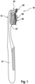
- Figs. 1 to 3 show an embodiment of an oral care implement 10, which could be a manual or an electrical toothbrush 10 comprising a handle 12 and a head 14 extending from the handle 12 in a longitudinal direction.
- a plurality of tufts 46, 47, 48, 50, 51, 26 is secured to the head 14 by means of a hot tufting or conventional stapling process.
- Each tuft 46, 47, 48, 50, 51, 26 comprises a plurality of filaments having free ends 30 and fixed ends 32 being opposite the free ends 30 and being fixed on a mounting surface 22 of the head 14.
- the longitudinal extension 28 of the head 14 extends between a proximal end 23 of the head 14 which is attached or attachable to the handle 12 and a distal end 24 being opposite the proximal end 23.
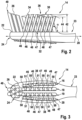
- a second row 16 of tufts 46, 47, 48 and a fourth row 20 of tufts 46, 47, 48 are arranged along the outer edge 38 of the mounting surface 22, while a first row 18 of tufts 50, 51 and a third row 19 of tufts 50, 51 (in the following also referred to as “inner rows” 18, 19) are arranged in the central part of the mounting surface 22, i.e. between the first row 18 and the fourth row 20.
- the filaments of each row 16, 18, 19, 20 extend from the mounting surface 22 of the head 14 in different length extensions so that the filaments' free ends 30 of each row 16, 18, 19, 20 define an upper top cleaning surface 34 in the form of a continuous wave-shape 36.
- a difference in length between the longest length extension 42 and the shortest length extension 44 may be from 1.5 mm to about 2.0 mm, optionally about 1.7 mm.
- Each row 16, 18, 19, 20 comprises seven tufts 46, 47, 48, 50, 51 each tuft 46, 47, 48, 50, 51 being composed of filaments having a longitudinal axis and a cross-sectional area extending in a plane which is perpendicular to the longitudinal axis.
- the filaments of the longest length extension 42 have a cross-sectional area which is smaller than the cross-sectional area of the filaments of the shortest length extension 44.
- the first tuft 47 being arranged closest to the proximal end 23, i.e. closest to the handle 12, may be composed of filaments having a substantially circular cross-sectional area with a diameter of about 0.178 mm (7 mil).
- the next two tufts 48 following the first tuft 47 may be composed of filaments having a substantially cross-sectional area with a diameter of about 0.203 mm (8 mil), the next following tuft 47 may be composed of filaments having a substantially cross-sectional area with a diameter of about 0.178 mm (7 mil), and the next following three tufts 46 which are most remote from the handle 12 may be composed of filaments having a substantially cross-sectional area with a diameter of about 0.152 mm (6 mil).
- the two tufts 48 following the first tuft 47 being arranged closest to the proximal end 23 of the head 14 comprise the filaments with the shortest length extension 44, whereas the three tufts 46 being most remote from the handle 12 comprise the filaments with the longest length extension 42.
- the distance 42 between the free ends 30 of the longest filaments and the mounting surface 22 may be about 11.2 mm, whereas the distance 44 between the free ends 30 of the shortest filaments and the mounting surface 22 may be about 9.5 mm.
- the first tuft 50 being arranged closest to the proximal end 23, i.e. closest the handle 12, may be composed of filaments having a substantially circular cross-sectional area with a diameter of about 0.152 mm (6 mil). These tufts 50 alternate with tufts 51 which may be composed of filaments having a substantially cross-sectional area with a diameter of about 0.203 mm (8 mil).
- the distance 42 between the free ends 30 of the longest filaments and the mounting surface 22 may be about 11.2 mm, whereas the distance 44 between the free ends 30 of the shortest filaments and the mounting surface 22 may be about 9.5 mm.
- the tufts 50, 51 of the inner rows 18, 19 are arranged in a manner that the continuous wave-shaped form is contra-cyclical with respect to the continuous wave-shaped form of the outer rows 16, 20.
- the tufts 46, 47, 48 of the outer rows 16, 20 may have a substantially circular cross-sectional area with a diameter of about 1.5 mm
- the tufts 50, 51 of the inner rows 18, 19 may have a substantially circular cross-sectional area with a diameter of about 2 mm. Since the diameters of the tufts 46, 47, 48 of the outer rows 16, 20 and of the tufts 50, 51 of the inner rows 18, 19, respectively, have substantially the same dimensions, the tufts 46, 50 comprising filaments with the smaller cross-sectional area comprise a higher number of filaments compared to the tufts 47, 48, 51 having filaments with the larger cross-sectional area.
- All tufts 46, 47, 48 of the outer rows 16, 20 are inclined toward the proximal end 23 of the head 14, i.e. toward the handle 12 relative to an imaginary line which is tangent to or co-planar with the mounting surface 22 of the head 14.
- the Tufts 50, 51 of the inner rows 18, 19 are inclined in the opposite direction, i.e. toward the distal end 24 of the head 14.
- the rows 16, 18, 19, 20 of tufts 46, 47, 48, 50, 51 define a criss-cross pattern when the head 14 is seen in a side view to improve cleaning properties when the toothbrush 10 is moved in the respective opposite directions.
- the tufts 46, 47, 48, 50, 51 of the rows 16, 18, 19, 20 may be inclined with respect to the mounting surface 22 by an inclination angle ⁇ from about 65° to about 80°, optionally from about 70° to about 80°, further optionally from about 74° to about 78°, even further optionally about 74° or about 75° to provide improved cleaning properties of the toothbrush 10.
- a crescent-shaped cluster 40 of tufts 26 is attached to the head 14.
- Each tuft 26 may have a substantially circular cross-sectional area with a diameter of about 2 mm and may be composed of filaments with a substantially circular cross-sectional area having a diameter of about 0.203 mm (8 mil).
- Each tuft 26 of the crescent-shaped cluster 40 may be angled by about 80° or less to an imaginary line which is tangent to or co-planar with the mounting surface 22 of the head 14 through which the tuft 26 is secured to the head 14.
- the tufts 26 of the crescent-shaped cluster 40 are tilted/angled away from the handle 12 and extend past the distal end 24 of the head 14 of the toothbrush 10 and, thus, may clean molars (e.g. wisdom teeth and second molars) in the back of the oral cavity in a more sufficient manner.
- molars e.g. wisdom teeth and second molars
- the term "substantially” refers to an arrangement of elements or features that, while in theory would be expected to exhibit exact correspondence or behavior, may, in practice embody something slightly less than exact. As such, the term denotes the degree by which a quantitative value, measurement or other related representation may vary from a stated reference without resulting in a change in the basic function of the subject matter at issue.
Claims (14)
- Tête (14) pour un instrument de soins bucco-dentaires (10) comprenant :au moins une première rangée (18) de touffes (50, 51) comprenant une pluralité de filaments ayant des extrémités libres (30) et des extrémités fixes (32) étant à l'opposé des extrémités libres (30) et étant fixées sur une surface de montage (22) de la tête (14),les filaments de l'au moins première rangée (18) de touffes (50, 51) s'étendant à partir de la surface de montage (22) de la tête (14) dans des rallonges de longueur différentes (42, 44) définissant de ce fait avec les extrémités libres de filaments (30) une surface de nettoyage de dessus supérieure (34) sous la forme d'un profil ondulé continu (36),chaque filament ayant un axe longitudinal et une aire en coupe transversale s'étendant dans un plan qui est perpendiculaire à l'axe longitudinal, dans laquelle chaque touffe (50, 51) de l'au moins première rangée (18) comprend soit des filaments avec une aire en coupe transversale plus petite soit des filaments avec une aire en coupe transversale plus grande, et les touffes (50, 51) sont agencées d'une manière alternée de sorte qu'une touffe (50) comprenant des filaments avec l'aire en coupe transversale plus petite alterne avec une touffe (51) comprenant des filaments avec l'aire en coupe transversale plus grande, dans laquelle chaque touffe (50, 51) de l'au moins première rangée (18) a un axe longitudinal et une aire en coupe transversale s'étendant dans un plan qui est perpendiculaire à l'axe longitudinal, et l'aire en coupe transversale de chaque touffe (50, 51) a sensiblement la même taille, et la touffe (50) comprenant les filaments avec l'aire en coupe transversale plus petite comprend une quantité plus élevée de filaments que la touffe (51) comprenant les filaments avec l'aire en coupe transversale plus grande.
- Tête (14) selon la revendication 1, dans laquelle les filaments ayant la coupe transversale plus petite ont une aire en coupe transversale sensiblement circulaire avec un diamètre d'environ 0,15 mm à environ 0,18 mm, éventuellement environ 0,152 mm (6 mil) ou environ 0,178 mm (7 mil).
- Tête (14) selon la revendication 1 ou 2, dans laquelle les filaments ayant l'aire en coupe transversale plus grande ont une aire en coupe transversale sensiblement circulaire avec un diamètre d'environ 0,20 mm à environ 0,23 mm, éventuellement environ 0,203 mm (8 mil) ou environ 0,229 mm (9 mil).
- Tête (14) selon l'une quelconque des revendications précédentes, dans laquelle une différence de longueur entre la rallonge de longueur la plus longue (42) et la rallonge de longueur la plus courte (44) est d'environ 1,5 mm à environ 2,0 mm, éventuellement environ 1,7 mm.
- Tête (14) selon l'une quelconque des revendications précédentes, dans laquelle la tête (14) a une rallonge longitudinale (28) s'étendant entre une extrémité proximale (23) de la tête (14) qui est attachée ou peut être attachée à une poignée (12) et une extrémité distale (24) étant à l'opposé de l'extrémité proximale (23), et l'au moins première rangée (18) de touffes (50, 51) est agencée sensiblement parallèle à la rallonge longitudinale (28) de la tête (14).
- Tête (14) selon l'une quelconque des revendications précédentes, dans laquelle la tête (14) comprend au moins une deuxième rangée (16) de touffes (46, 47, 48) comprenant une pluralité de filaments, la deuxième rangée (16) étant sensiblement parallèle à la première rangée (18), et les filaments de la deuxième rangée (16) s'étendent depuis la surface de montage (22) dans des rallonges de longueur différentes (42, 44) définissant de ce fait avec les extrémités libres de filaments (30) une surface de nettoyage de dessus supérieure (34) sous la forme d'un profil ondulé continu (36), et
chaque filament de la deuxième rangée (16) a un axe longitudinal et une aire en coupe transversale s'étendant dans un plan qui est perpendiculaire à l'axe longitudinal, et les filaments de la rallonge de longueur la plus longue (42) ont une aire en coupe transversale étant plus petite que l'aire en coupe transversale des filaments de la rallonge de longueur la plus courte (44). - Tête (14) selon la revendication 6, dans laquelle les touffes (46, 47, 48) de la deuxième rangée (16) sont agencées de manière à ce que la forme de profil ondulé soit contracyclique par rapport à la forme de profil ondulé de la première rangée (18).
- Tête (14) selon la revendication 6 ou 7, dans laquelle la tête (14) comprend une troisième rangée (19) de touffes (50, 51) comprenant une pluralité de filaments et une quatrième rangée (20) de touffes (46, 47, 48) comprenant une pluralité de filaments, la troisième rangée (19) et la quatrième rangée (20) étant sensiblement parallèles à la première rangée (18) et à la deuxième rangée (16).
- Tête (14) selon la revendication 8, dans laquelle la troisième rangée (19) a la même configuration de touffe (50, 51) que la première rangée (18), et la quatrième rangée (20) a la même configuration de touffe (46, 47, 48) que la deuxième rangée (16), et la deuxième rangée (16) et la quatrième rangée (20) sont agencées au niveau des bords externes respectifs (38) de la surface de montage (22) de la tête (14), et la première rangée (18) et la troisième rangée (19) sont agencées entre la deuxième rangée (16) et la quatrième rangée (20).
- Tête (14) selon l'une quelconque des revendications précédentes, dans laquelle les touffes (50, 51) de l'au moins première rangée (18) sont inclinées par rapport à la surface de montage (22) dans une direction sensiblement parallèle à la rallonge longitudinale (28) de la tête (14).
- Tête (14) selon la revendication 10, dans laquelle les touffes (46, 47, 48) de la deuxième rangée (16) sont inclinées dans la direction opposée par rapport à la première rangée (18).
- Tête (14) selon l'une quelconque des revendications 8 à 11, dans laquelle les touffes (46, 47, 48) de la deuxième rangée (16) et les touffes (46, 47, 48) de la quatrième rangée (20) sont inclinées dans une direction vers l'extrémité proximale (23) de la tête (14), et les touffes (50, 51) de la première rangée (18) et les touffes (50, 51) de la troisième rangée (19) sont inclinées dans une direction vers l'extrémité distale (24) de la tête (14).
- Tête (14) selon l'une quelconque des revendications précédentes, dans laquelle les touffes (46, 47, 48, 50, 51) sont inclinées par rapport à la surface de montage (22) selon un angle d'inclinaison (α) d'environ 65° à environ 80°, éventuellement d'environ 70° à environ 80°, éventuellement en outre d'environ 74° à environ 78°, voire éventuellement en outre d'environ 74° à environ 75°.
- Instrument de soins bucco-dentaires (10) comprenant une tête (14) selon l'une quelconque des revendications précédentes.
Priority Applications (9)
| Application Number | Priority Date | Filing Date | Title |
|---|---|---|---|
| EP14193799.5A EP3023030B1 (fr) | 2014-11-19 | 2014-11-19 | Tête pour un instrument de soin buccal |
| MX2017006346A MX2017006346A (es) | 2014-11-19 | 2015-11-19 | Cabezal para un implemento para el cuidado bucal. |
| AU2015349916A AU2015349916B2 (en) | 2014-11-19 | 2015-11-19 | Head for an oral care implement |
| KR1020177013280A KR20170073629A (ko) | 2014-11-19 | 2015-11-19 | 구강 케어 기구용 헤드 |
| PCT/US2015/061512 WO2016081696A1 (fr) | 2014-11-19 | 2015-11-19 | Tête pour accessoire d'hygiène bucco-dentaire |
| US14/946,566 US10149532B2 (en) | 2014-11-19 | 2015-11-19 | Head for an oral care implement |
| CN201580062112.2A CN106998898B (zh) | 2014-11-19 | 2015-11-19 | 用于口腔护理工具的头部 |
| CA2967651A CA2967651C (fr) | 2014-11-19 | 2015-11-19 | Arrangement de filament en forme de vague destine a un accessoire de soin buccal |
| BR112017010228-5A BR112017010228B1 (pt) | 2014-11-19 | 2015-11-19 | Cabeça de escova de dente para um implemento para tratamento bucal e implemento para tratamento bucal |
Applications Claiming Priority (1)
| Application Number | Priority Date | Filing Date | Title |
|---|---|---|---|
| EP14193799.5A EP3023030B1 (fr) | 2014-11-19 | 2014-11-19 | Tête pour un instrument de soin buccal |
Publications (2)
| Publication Number | Publication Date |
|---|---|
| EP3023030A1 EP3023030A1 (fr) | 2016-05-25 |
| EP3023030B1 true EP3023030B1 (fr) | 2023-11-22 |
Family
ID=51932235
Family Applications (1)
| Application Number | Title | Priority Date | Filing Date |
|---|---|---|---|
| EP14193799.5A Active EP3023030B1 (fr) | 2014-11-19 | 2014-11-19 | Tête pour un instrument de soin buccal |
Country Status (9)
| Country | Link |
|---|---|
| US (1) | US10149532B2 (fr) |
| EP (1) | EP3023030B1 (fr) |
| KR (1) | KR20170073629A (fr) |
| CN (1) | CN106998898B (fr) |
| AU (1) | AU2015349916B2 (fr) |
| BR (1) | BR112017010228B1 (fr) |
| CA (1) | CA2967651C (fr) |
| MX (1) | MX2017006346A (fr) |
| WO (1) | WO2016081696A1 (fr) |
Families Citing this family (19)
| Publication number | Priority date | Publication date | Assignee | Title |
|---|---|---|---|---|
| USD724324S1 (en) * | 2012-06-20 | 2015-03-17 | Braun Gmbh | Toothbrush head with tongue cleaner |
| EP3501335B1 (fr) | 2017-12-20 | 2020-06-17 | The Gillette Company LLC | Brosse à dents |
| EP3501336A1 (fr) | 2017-12-20 | 2019-06-26 | The Gillette Company LLC | Outil de soin buccal |
| USD960581S1 (en) | 2018-02-09 | 2022-08-16 | The Gillette Company Llc | Toothbrush head |
| USD912988S1 (en) | 2018-02-09 | 2021-03-16 | The Gillette Company Llc | Toothbrush handle |
| US11388985B2 (en) | 2018-02-09 | 2022-07-19 | The Gillette Company Llc | Connector for a manual oral care implement |
| EP3524093A1 (fr) | 2018-02-09 | 2019-08-14 | The Gillette Company LLC | Procédé de fabrication d'un instrument de soin buccal |
| EP3524092A1 (fr) | 2018-02-09 | 2019-08-14 | The Gillette Company LLC | Connecteur pour un instrument de soin buccal manuel |
| US11400627B2 (en) | 2018-02-09 | 2022-08-02 | The Gillette Company Llc | Method for manufacturing an oral care implement |
| PL3616561T3 (pl) | 2018-09-03 | 2022-11-21 | The Gillette Company Llc | Główka do narzędzia do higieny jamy ustnej i zestaw zawierający taką główkę |
| US11659922B2 (en) | 2018-09-03 | 2023-05-30 | The Gillette Company, LLC. | Head for an oral-care implement and a kit comprising such head |
| USD931617S1 (en) | 2018-09-03 | 2021-09-28 | The Gillette Company Llc | Toothbrush head |
| USD901183S1 (en) | 2019-03-22 | 2020-11-10 | The Gillette Company Llc | Toothbrush |
| EP3714732A1 (fr) | 2019-03-29 | 2020-09-30 | The Gillette Company LLC | Tête d'instrument pour soins buccaux et instrument pour soins buccaux |
| EP3818904A1 (fr) | 2019-11-06 | 2021-05-12 | The Gillette Company LLC | Poignée pour un instrument de soins personnels à commande électrique |
| EP3995282A1 (fr) * | 2020-11-06 | 2022-05-11 | The Gillette Company LLC | Procédé de fabrication d'une poignée pour un instrument de soins personnels |
| USD1014095S1 (en) | 2020-07-02 | 2024-02-13 | The Gillette Company Llc. | Toothbrush |
| USD957135S1 (en) | 2020-07-02 | 2022-07-12 | The Gillette Company Llc | Toothbrush head |
| USD994341S1 (en) | 2020-11-06 | 2023-08-08 | The Gillette Company Llc | Toothbrush |
Family Cites Families (21)
| Publication number | Priority date | Publication date | Assignee | Title |
|---|---|---|---|---|
| US5305489A (en) * | 1990-08-28 | 1994-04-26 | Lage Gregg L | Ergonomic topographic toothbrush |
| US5392483A (en) * | 1994-07-07 | 1995-02-28 | Chesebrough-Pond's Usa Co., Division Of Conopco, Inc. | Multi-level bristle tuft toothbrush |
| US5628082A (en) * | 1995-03-22 | 1997-05-13 | Colgate-Palmolive Company | Toothbrush with improved efficacy |
| ES2192797T5 (es) * | 1997-11-12 | 2009-03-01 | Gillette Canada Company | Cepillo de dientes. |
| US6308367B1 (en) * | 1997-11-12 | 2001-10-30 | Gillette Canada Company | Toothbrush |
| US20020004964A1 (en) * | 1999-12-15 | 2002-01-17 | Luchino Thomas Patrick | Toothbrush with individually embedded bristles |
| US6405401B1 (en) * | 2001-07-02 | 2002-06-18 | Colgate-Palmolive Company | Toothbrush having a bristle pattern which provides enhanced cleaning |
| GB0123939D0 (en) * | 2001-10-05 | 2001-11-28 | Glaxosmithkline Consumer Healt | Toothbrush |
| AU2003252861A1 (en) * | 2003-10-07 | 2005-04-21 | Gillette Canada Inc. | Cleaning Device |
| RU2422116C2 (ru) | 2006-09-08 | 2011-06-27 | Дзе Жиллетт Компани | Устройство для гигиены ротовой полости, зубная щетка (варианты) и способ обеспечения множества чистящих операций единственной зубной щеткой |
| KR101477326B1 (ko) * | 2007-12-18 | 2014-12-29 | 라이온 가부시키가이샤 | 칫솔 |
| EP2181621A1 (fr) * | 2008-10-28 | 2010-05-05 | Braun Gmbh | Brosse à dents |
| US20100115724A1 (en) * | 2008-11-13 | 2010-05-13 | Acumen Co., Ltd. | Brush head of a toothbrush |
| AR074602A1 (es) * | 2008-12-15 | 2011-01-26 | Glaxosmithkline Consumer Healt | Una cabeza de cepillo de dientes |
| US20100325827A1 (en) * | 2009-06-26 | 2010-12-30 | Shou-Jen Huang | Toothbrush |
| CN201468403U (zh) * | 2009-08-27 | 2010-05-19 | 何钜楠 | 直接去渍牙刷 |
| WO2012057157A1 (fr) * | 2010-10-29 | 2012-05-03 | ライオン株式会社 | Brosse à dents |
| US20120291212A1 (en) * | 2011-05-16 | 2012-11-22 | Montagnino James G | Resonant vibration-enhancing cleaning attachment for an ultrasonic powered handle |
| ES2593132T3 (es) * | 2011-07-06 | 2016-12-05 | Braun Gmbh | Sección de limpieza para un dispositivo de higiene bucodental eléctrico |
| EP2810583B1 (fr) * | 2013-06-06 | 2018-05-23 | The Procter and Gamble Company | Tête pour un instrument de soin buccal |
| ES2707385T3 (es) * | 2014-04-11 | 2019-04-03 | Procter & Gamble | Cabezal para un utensilio de cuidado bucal |
-
2014
- 2014-11-19 EP EP14193799.5A patent/EP3023030B1/fr active Active
-
2015
- 2015-11-19 US US14/946,566 patent/US10149532B2/en active Active
- 2015-11-19 BR BR112017010228-5A patent/BR112017010228B1/pt active IP Right Grant
- 2015-11-19 MX MX2017006346A patent/MX2017006346A/es active IP Right Grant
- 2015-11-19 AU AU2015349916A patent/AU2015349916B2/en active Active
- 2015-11-19 KR KR1020177013280A patent/KR20170073629A/ko active Search and Examination
- 2015-11-19 CA CA2967651A patent/CA2967651C/fr active Active
- 2015-11-19 CN CN201580062112.2A patent/CN106998898B/zh active Active
- 2015-11-19 WO PCT/US2015/061512 patent/WO2016081696A1/fr active Application Filing
Also Published As
| Publication number | Publication date |
|---|---|
| US20160135580A1 (en) | 2016-05-19 |
| WO2016081696A1 (fr) | 2016-05-26 |
| KR20170073629A (ko) | 2017-06-28 |
| CA2967651C (fr) | 2019-04-23 |
| MX2017006346A (es) | 2017-08-21 |
| CN106998898A (zh) | 2017-08-01 |
| AU2015349916B2 (en) | 2018-11-15 |
| EP3023030A1 (fr) | 2016-05-25 |
| BR112017010228B1 (pt) | 2022-09-13 |
| CN106998898B (zh) | 2020-03-03 |
| BR112017010228A2 (pt) | 2018-01-02 |
| AU2015349916A1 (en) | 2017-05-25 |
| CA2967651A1 (fr) | 2016-05-26 |
| US10149532B2 (en) | 2018-12-11 |
Similar Documents
| Publication | Publication Date | Title |
|---|---|---|
| US10149532B2 (en) | Head for an oral care implement | |
| US10021962B2 (en) | Head for an oral care implement | |
| US11641932B2 (en) | Head for an oral care implement | |
| EP2910143B1 (fr) | Tête pour un instrument de soin buccal | |
| US10537169B2 (en) | Head for an oral care implement | |
| AU2015243544A1 (en) | Head for an oral care implement | |
| CA2914480A1 (fr) | Tete pour un instrument de soins bucco-dentaire |
Legal Events
| Date | Code | Title | Description |
|---|---|---|---|
| AK | Designated contracting states |
Kind code of ref document: A1 Designated state(s): AL AT BE BG CH CY CZ DE DK EE ES FI FR GB GR HR HU IE IS IT LI LT LU LV MC MK MT NL NO PL PT RO RS SE SI SK SM TR |
|
| AX | Request for extension of the european patent |
Extension state: BA ME |
|
| PUAI | Public reference made under article 153(3) epc to a published international application that has entered the european phase |
Free format text: ORIGINAL CODE: 0009012 |
|
| STAA | Information on the status of an ep patent application or granted ep patent |
Free format text: STATUS: REQUEST FOR EXAMINATION WAS MADE |
|
| RAP1 | Party data changed (applicant data changed or rights of an application transferred) |
Owner name: THE GILLETTE COMPANY LLC |
|
| 17P | Request for examination filed |
Effective date: 20161122 |
|
| RBV | Designated contracting states (corrected) |
Designated state(s): AL AT BE BG CH CY CZ DE DK EE ES FI FR GB GR HR HU IE IS IT LI LT LU LV MC MK MT NL NO PL PT RO RS SE SI SK SM TR |
|
| STAA | Information on the status of an ep patent application or granted ep patent |
Free format text: STATUS: EXAMINATION IS IN PROGRESS |
|
| 17Q | First examination report despatched |
Effective date: 20191001 |
|
| STAA | Information on the status of an ep patent application or granted ep patent |
Free format text: STATUS: EXAMINATION IS IN PROGRESS |
|
| P01 | Opt-out of the competence of the unified patent court (upc) registered |
Effective date: 20230430 |
|
| GRAP | Despatch of communication of intention to grant a patent |
Free format text: ORIGINAL CODE: EPIDOSNIGR1 |
|
| STAA | Information on the status of an ep patent application or granted ep patent |
Free format text: STATUS: GRANT OF PATENT IS INTENDED |
|
| INTG | Intention to grant announced |
Effective date: 20230712 |
|
| GRAS | Grant fee paid |
Free format text: ORIGINAL CODE: EPIDOSNIGR3 |
|
| GRAA | (expected) grant |
Free format text: ORIGINAL CODE: 0009210 |
|
| STAA | Information on the status of an ep patent application or granted ep patent |
Free format text: STATUS: THE PATENT HAS BEEN GRANTED |
|
| AK | Designated contracting states |
Kind code of ref document: B1 Designated state(s): AL AT BE BG CH CY CZ DE DK EE ES FI FR GB GR HR HU IE IS IT LI LT LU LV MC MK MT NL NO PL PT RO RS SE SI SK SM TR |
|
| REG | Reference to a national code |
Ref country code: GB Ref legal event code: FG4D |
|
| REG | Reference to a national code |
Ref country code: CH Ref legal event code: EP Ref country code: DE Ref legal event code: R096 Ref document number: 602014088927 Country of ref document: DE |
|
| REG | Reference to a national code |
Ref country code: IE Ref legal event code: FG4D |
|
| REG | Reference to a national code |
Ref country code: NL Ref legal event code: FP |
|
| REG | Reference to a national code |
Ref country code: LT Ref legal event code: MG9D |
|
| PG25 | Lapsed in a contracting state [announced via postgrant information from national office to epo] |
Ref country code: GR Free format text: LAPSE BECAUSE OF FAILURE TO SUBMIT A TRANSLATION OF THE DESCRIPTION OR TO PAY THE FEE WITHIN THE PRESCRIBED TIME-LIMIT Effective date: 20240223 |
|
| PG25 | Lapsed in a contracting state [announced via postgrant information from national office to epo] |
Ref country code: IS Free format text: LAPSE BECAUSE OF FAILURE TO SUBMIT A TRANSLATION OF THE DESCRIPTION OR TO PAY THE FEE WITHIN THE PRESCRIBED TIME-LIMIT Effective date: 20240322 |
|
| PG25 | Lapsed in a contracting state [announced via postgrant information from national office to epo] |
Ref country code: LT Free format text: LAPSE BECAUSE OF FAILURE TO SUBMIT A TRANSLATION OF THE DESCRIPTION OR TO PAY THE FEE WITHIN THE PRESCRIBED TIME-LIMIT Effective date: 20231122 |
|
| REG | Reference to a national code |
Ref country code: AT Ref legal event code: MK05 Ref document number: 1633041 Country of ref document: AT Kind code of ref document: T Effective date: 20231122 |
|
| PG25 | Lapsed in a contracting state [announced via postgrant information from national office to epo] |
Ref country code: AT Free format text: LAPSE BECAUSE OF FAILURE TO SUBMIT A TRANSLATION OF THE DESCRIPTION OR TO PAY THE FEE WITHIN THE PRESCRIBED TIME-LIMIT Effective date: 20231122 |
|
| PG25 | Lapsed in a contracting state [announced via postgrant information from national office to epo] |
Ref country code: ES Free format text: LAPSE BECAUSE OF FAILURE TO SUBMIT A TRANSLATION OF THE DESCRIPTION OR TO PAY THE FEE WITHIN THE PRESCRIBED TIME-LIMIT Effective date: 20231122 |
|
| PG25 | Lapsed in a contracting state [announced via postgrant information from national office to epo] |
Ref country code: LT Free format text: LAPSE BECAUSE OF FAILURE TO SUBMIT A TRANSLATION OF THE DESCRIPTION OR TO PAY THE FEE WITHIN THE PRESCRIBED TIME-LIMIT Effective date: 20231122 Ref country code: IS Free format text: LAPSE BECAUSE OF FAILURE TO SUBMIT A TRANSLATION OF THE DESCRIPTION OR TO PAY THE FEE WITHIN THE PRESCRIBED TIME-LIMIT Effective date: 20240322 Ref country code: GR Free format text: LAPSE BECAUSE OF FAILURE TO SUBMIT A TRANSLATION OF THE DESCRIPTION OR TO PAY THE FEE WITHIN THE PRESCRIBED TIME-LIMIT Effective date: 20240223 Ref country code: ES Free format text: LAPSE BECAUSE OF FAILURE TO SUBMIT A TRANSLATION OF THE DESCRIPTION OR TO PAY THE FEE WITHIN THE PRESCRIBED TIME-LIMIT Effective date: 20231122 Ref country code: BG Free format text: LAPSE BECAUSE OF FAILURE TO SUBMIT A TRANSLATION OF THE DESCRIPTION OR TO PAY THE FEE WITHIN THE PRESCRIBED TIME-LIMIT Effective date: 20240222 Ref country code: AT Free format text: LAPSE BECAUSE OF FAILURE TO SUBMIT A TRANSLATION OF THE DESCRIPTION OR TO PAY THE FEE WITHIN THE PRESCRIBED TIME-LIMIT Effective date: 20231122 Ref country code: PT Free format text: LAPSE BECAUSE OF FAILURE TO SUBMIT A TRANSLATION OF THE DESCRIPTION OR TO PAY THE FEE WITHIN THE PRESCRIBED TIME-LIMIT Effective date: 20240322 |