EP3022832B1 - Driving device of electric folding type side view mirror for a vehicle - Google Patents
Driving device of electric folding type side view mirror for a vehicle Download PDFInfo
- Publication number
- EP3022832B1 EP3022832B1 EP14744199.2A EP14744199A EP3022832B1 EP 3022832 B1 EP3022832 B1 EP 3022832B1 EP 14744199 A EP14744199 A EP 14744199A EP 3022832 B1 EP3022832 B1 EP 3022832B1
- Authority
- EP
- European Patent Office
- Prior art keywords
- cap
- driving device
- view mirror
- folding type
- type side
- Prior art date
- Legal status (The legal status is an assumption and is not a legal conclusion. Google has not performed a legal analysis and makes no representation as to the accuracy of the status listed.)
- Active
Links
Images



Classifications
-
- B—PERFORMING OPERATIONS; TRANSPORTING
- B60—VEHICLES IN GENERAL
- B60R—VEHICLES, VEHICLE FITTINGS, OR VEHICLE PARTS, NOT OTHERWISE PROVIDED FOR
- B60R1/00—Optical viewing arrangements; Real-time viewing arrangements for drivers or passengers using optical image capturing systems, e.g. cameras or video systems specially adapted for use in or on vehicles
- B60R1/02—Rear-view mirror arrangements
- B60R1/06—Rear-view mirror arrangements mounted on vehicle exterior
- B60R1/062—Rear-view mirror arrangements mounted on vehicle exterior with remote control for adjusting position
- B60R1/07—Rear-view mirror arrangements mounted on vehicle exterior with remote control for adjusting position by electrically powered actuators
- B60R1/074—Rear-view mirror arrangements mounted on vehicle exterior with remote control for adjusting position by electrically powered actuators for retracting the mirror arrangements to a non-use position alongside the vehicle
-
- B—PERFORMING OPERATIONS; TRANSPORTING
- B60—VEHICLES IN GENERAL
- B60R—VEHICLES, VEHICLE FITTINGS, OR VEHICLE PARTS, NOT OTHERWISE PROVIDED FOR
- B60R1/00—Optical viewing arrangements; Real-time viewing arrangements for drivers or passengers using optical image capturing systems, e.g. cameras or video systems specially adapted for use in or on vehicles
- B60R1/02—Rear-view mirror arrangements
- B60R1/06—Rear-view mirror arrangements mounted on vehicle exterior
- B60R1/062—Rear-view mirror arrangements mounted on vehicle exterior with remote control for adjusting position
- B60R1/07—Rear-view mirror arrangements mounted on vehicle exterior with remote control for adjusting position by electrically powered actuators
-
- G—PHYSICS
- G02—OPTICS
- G02B—OPTICAL ELEMENTS, SYSTEMS OR APPARATUS
- G02B7/00—Mountings, adjusting means, or light-tight connections, for optical elements
- G02B7/18—Mountings, adjusting means, or light-tight connections, for optical elements for prisms; for mirrors
- G02B7/182—Mountings, adjusting means, or light-tight connections, for optical elements for prisms; for mirrors for mirrors
- G02B7/1822—Mountings, adjusting means, or light-tight connections, for optical elements for prisms; for mirrors for mirrors comprising means for aligning the optical axis
- G02B7/1827—Motorised alignment
-
- H—ELECTRICITY
- H02—GENERATION; CONVERSION OR DISTRIBUTION OF ELECTRIC POWER
- H02K—DYNAMO-ELECTRIC MACHINES
- H02K5/00—Casings; Enclosures; Supports
- H02K5/04—Casings or enclosures characterised by the shape, form or construction thereof
-
- H—ELECTRICITY
- H02—GENERATION; CONVERSION OR DISTRIBUTION OF ELECTRIC POWER
- H02K—DYNAMO-ELECTRIC MACHINES
- H02K7/00—Arrangements for handling mechanical energy structurally associated with dynamo-electric machines, e.g. structural association with mechanical driving motors or auxiliary dynamo-electric machines
- H02K7/10—Structural association with clutches, brakes, gears, pulleys or mechanical starters
- H02K7/116—Structural association with clutches, brakes, gears, pulleys or mechanical starters with gears
- H02K7/1163—Structural association with clutches, brakes, gears, pulleys or mechanical starters with gears where at least two gears have non-parallel axes without having orbital motion
- H02K7/1166—Structural association with clutches, brakes, gears, pulleys or mechanical starters with gears where at least two gears have non-parallel axes without having orbital motion comprising worm and worm-wheel
-
- Y—GENERAL TAGGING OF NEW TECHNOLOGICAL DEVELOPMENTS; GENERAL TAGGING OF CROSS-SECTIONAL TECHNOLOGIES SPANNING OVER SEVERAL SECTIONS OF THE IPC; TECHNICAL SUBJECTS COVERED BY FORMER USPC CROSS-REFERENCE ART COLLECTIONS [XRACs] AND DIGESTS
- Y10—TECHNICAL SUBJECTS COVERED BY FORMER USPC
- Y10S—TECHNICAL SUBJECTS COVERED BY FORMER USPC CROSS-REFERENCE ART COLLECTIONS [XRACs] AND DIGESTS
- Y10S248/00—Supports
- Y10S248/90—Movable or disengageable on impact or overload
Definitions
- the present invention relates to a driving device of an electric folding type side view mirror for a vehicle in line with the preamble of claim 1, and, more particularly, to a driving device of an electric folding type side view mirror for a vehicle that does not cause thrust sounds when using a rotational axis of a motor as a buffer means.
- the side view mirror is protruded at a front left and right side of the vehicle and therefore there is a possibility that minor accidents may occur due to the side view mirror when parking the vehicle in a confined space or intersecting the vehicle on a narrow road.
- an electric folding type side view mirror that may conveniently be folded and unfolded by a driver at a driver's seat has been developed.
- the known electric folding type side view mirror controls a position of a back mirror using a driving device that transfers rotation power from an electric motor seated at an upper case using a worm wheel.
- EP 2 301 804 A1 discloses a driving device in line with the preamble of claim 1.
- the known drive device makes usage of a drive mechanism which can be uncoupled when from outside a high adjusting force is exerted on a hinge construction between the vehicle and a mirror frame.
- Korean Patent Registration No. 10-0543643 as an example of a prior art driving device of the electric folding type side view mirror for the vehicle, discloses a technology that may minimize generation of noises, although the rotational axis of the motor is not maintained vertically, by supporting the lower end of the rotational axis of the motor so as not to be interfered with, and that a motor body section fixed by a motor cap absorbs and buffers thrust using a back plate and spacer.
- a belt-tensioning drive that is compactly built and easy to install is known from DE 10 2007 038 916 A1 .
- An object of the invention is to provide a driving device of an electric folding type side view mirror for a vehicle substantially avoiding thrust sounds.
- a driving device of an electric folding type side view mirror for a vehicle comprising an upper case in which a motor seating part is formed; an electric motor, installed inside the upper case, for generating rotation power; a worm gear installed at a rotational axis of the electric motor; a worm wheel gear, connected to the worm gear, for transferring the rotation power; a lower case formed with a fixing means; a cap spring fixed to the lower case by the fixing means; and a cap, mounted at a top of the cap spring, for receiving a lower end of the rotational axis.
- the lower end of the rotational axis of the electric motor extends beyond the upper case such that it can apply a pressing action to the cap and cap spring.
- the center section on the top surface of the cap is formed with a hole for receiving the lower end of the rotational axis of the electric motor.
- a plurality of bending sections for fixing the cap spring is disposed at the cap while forming circles.
- the fixing means for fixing the cap spring in the lower case is formed with a boss, preferably having a saw-toothed wheel type outer peripheral surface onto which the cap spring is seated.
- the fixing means for fixing the cap spring in the lower case is formed with a rib, preferably formed by two lines in order to be inserted with the cap spring.
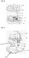
- FIG. 1 is an entire exploded perspective view for a driving device of electric folding type side view mirror for a vehicle according to a first embodiment of the present invention
- FIG. 2 is an exploded perspective view of an upper case and a lower case of the driving device of the electric folding type side view mirror for the vehicle according to the first embodiment of the present invention
- FIG. 3 is an exploded perspective view of an upper case and a lower case of the driving device of the electric folding type side view mirror for the vehicle according to the first embodiment of the present invention
- FIG. 4 is a cross-sectional view of the driving device of the electric folding type side view mirror for the vehicle according to the first embodiment of the present invention
- FIG. 1 is an entire exploded perspective view for a driving device of electric folding type side view mirror for a vehicle according to a first embodiment of the present invention
- FIG. 2 is an exploded perspective view of an upper case and a lower case of the driving device of the electric folding type side view mirror for the vehicle according to the first embodiment of the present invention
- FIG. 3 is an exploded perspective view
- FIG. 5 is a perspective view of the lower case of the driving device of the electric folding type side view mirror for the vehicle according to the first embodiment of the present invention
- FIG. 6 is a partial cross-sectional view showing a section disposing a cap and spring of the driving device of the electric folding type side view mirror for the vehicle according to the first embodiment of the present invention
- FIG. 7 is a perspective view of the cap and spring of the driving device of the electric folding type side view mirror for a vehicle according to the first embodiment of the present invention
- FIG. 8 is a perspective view of the cap of the driving device of the electric folding type side view mirror for the vehicle according to the first embodiment of the present invention.
- the driving device of electric folding type side view mirror for the vehicle comprises an upper case 30, in which a motor seating part is formed; an electric motor 40, disposed inside the upper case 30, for generating rotation power; a worm gear 11 disposed at a rotational axis 41 of the electric motor 40; a worm wheel gear 12, connected to the worm gear 11, for transferring rotation power; a lower case 20 with a base 10 formed with a boss 15 for fixing a spring; a cap spring 14 fixed to the boss 15 for fixing the spring; and a cap 13, mounted at a top of the cap spring 14, for receiving a lower end of the rotational axis 41.
- the upper case 30 is coupled with the lower case 20, and a cover 50 is covers the outside of these components.
- a lower end of the rotational axis 41 of the electric motor 40 is protruded to be longer than that of the upper case 30, and presses the cap 13 and cap spring 14, thereby preventing thrust sounds.
- a center section on a top surface of the cap 13 is formed with a hole 131 for receiving the lower end of the rotational axis 41 of the electric motor 40, and four bending sections 132 for fixing the cap spring 14 are disposed distant by an interval of 90° while forming a circle.
- the cap spring 14 is formed with a compression coil spring.
- the lower case 20 provides a recess for accommodating the cap 13 and the cap spring 14 with a fixing means for the cap spring 14 in form of a boss 21 on which the cap spring 14 is arranged.
- An outer peripheral surface of the boss 21, for fixing the cap spring 14, of the lower case 20 is formed with a saw-toothed wheel type.
- FIG. 9 is a perspective view of the lower case of the driving device of the electric folding type side view mirror for the vehicle according to a second embodiment of the present invention
- FIG. 10 is a partial cross-sectional view showing a section disposing the cap and spring of the driving device of the electric folding type side view mirror for the vehicle according to the second embodiment of the present invention.
- configurations of the driving device of electric folding type side view mirror for the vehicle according to a second embodiment of the present invention are configured with the same structures as those of the first embodiment, except for the fact that a rib 22 for fixing the cap spring 14 is formed in the lower case 20.
- the rib 22 for fixing the cap spring 14 in the lower case 20 is formed with the structure formed by two lines in order to insert the cap spring 14 into the rib 20.
- the driving device of the electric folding type side view mirror for the vehicle according to an embodiment of the present invention is operated, as follows.
- the rotational axis 41 of the electric motor 40 causes thrust vertically at an end play interval by a component force of the worm gear 11 so that the cap 13 and cap spring 14 are operated to absorb operation sounds caused by the thrust, thereby preventing thrust sounds.
- the upper end of the cap spring 14 is fixed into the bending section 132 of the cap 13, and the lower end of it is fixed into the boss 21 for fixing the spring or the rib 22 for fixing the spring in the lower case 20, thereby providing buffer power for absorbing operation sounds due to the thrust.
Landscapes
- Engineering & Computer Science (AREA)
- Power Engineering (AREA)
- Multimedia (AREA)
- Mechanical Engineering (AREA)
- Physics & Mathematics (AREA)
- General Physics & Mathematics (AREA)
- Optics & Photonics (AREA)
- Rear-View Mirror Devices That Are Mounted On The Exterior Of The Vehicle (AREA)
Description
- The present invention relates to a driving device of an electric folding type side view mirror for a vehicle in line with the preamble of claim 1, and, more particularly, to a driving device of an electric folding type side view mirror for a vehicle that does not cause thrust sounds when using a rotational axis of a motor as a buffer means.
- Side view mirrors play very important roles for safe driving so that a driver may grasp situations around a vehicle when driving the vehicle.
- However, the side view mirror is protruded at a front left and right side of the vehicle and therefore there is a possibility that minor accidents may occur due to the side view mirror when parking the vehicle in a confined space or intersecting the vehicle on a narrow road.
- In order to solve this problem, an electric folding type side view mirror that may conveniently be folded and unfolded by a driver at a driver's seat has been developed. The known electric folding type side view mirror controls a position of a back mirror using a driving device that transfers rotation power from an electric motor seated at an upper case using a worm wheel.
-
EP 2 301 804 A1 discloses a driving device in line with the preamble of claim 1. The known drive device makes usage of a drive mechanism which can be uncoupled when from outside a high adjusting force is exerted on a hinge construction between the vehicle and a mirror frame. - Korean Patent Registration No.
10-0543643 - However, there is a problem in that this known technology still causes thrust sounds in the driving device of the electric folding type side view mirror for the vehicle described above.
- A belt-tensioning drive that is compactly built and easy to install is known from
DE 10 2007 038 916 A1 . - An object of the invention is to provide a driving device of an electric folding type side view mirror for a vehicle substantially avoiding thrust sounds.
- This object is achieved by the features of claim 1.
- Preferred embodiments of the invention are described in the claims 2 to 6.
providing a driving device of an electric folding type side view mirror for a vehicle comprising an upper case in which a motor seating part is formed; an electric motor, installed inside the upper case, for generating rotation power; a worm gear installed at a rotational axis of the electric motor; a worm wheel gear, connected to the worm gear, for transferring the rotation power; a lower case formed with a fixing means; a cap spring fixed to the lower case by the fixing means; and a cap, mounted at a top of the cap spring, for receiving a lower end of the rotational axis. - It is preferable that the lower end of the rotational axis of the electric motor extends beyond the upper case such that it can apply a pressing action to the cap and cap spring.
- It is preferable that the center section on the top surface of the cap is formed with a hole for receiving the lower end of the rotational axis of the electric motor.
- It is preferable that a plurality of bending sections for fixing the cap spring is disposed at the cap while forming circles.
- It is preferable that the fixing means for fixing the cap spring in the lower case is formed with a boss, preferably having a saw-toothed wheel type outer peripheral surface onto which the cap spring is seated.
- It is preferable that the fixing means for fixing the cap spring in the lower case is formed with a rib, preferably formed by two lines in order to be inserted with the cap spring.
-
- FIG. 1
- is an entire exploded perspective view for a driving device of an electric folding type side view mirror for a vehicle according to a first embodiment of the present invention.
- FIG. 2
- is an exploded perspective view of an upper case and an lower case of the driving device of the electric folding type side view mirror for the vehicle according to the first embodiment of the present invention.
- FIG. 3
- is an exploded perspective view of an upper case and an lower case of the driving device of the electric folding type side view mirror for the vehicle according to the first embodiment of the present invention.
- FIG. 4
- is a cross-sectional view of the driving device of the electric folding type side view mirror for the vehicle according to the first embodiment of the present invention.
- FIG. 5
- is a perspective view of the lower case of the driving device of the electric folding type side view mirror for the vehicle according to the first embodiment of the present invention.
- FIG. 6
- is a partial cross-sectional view showing a section with a cap and spring of the driving device of the electric folding type side view mirror for the vehicle according to the first embodiment of the present invention.
- FIG. 7
- is a perspective view of the cap and spring of the driving device of the electric folding type side view mirror for a vehicle according to the first embodiment of the present invention.
- FIG. 8
- is a perspective view of the cap of the driving device of the electric folding type side view mirror for the vehicle according to the first embodiment of the present invention.
- FIG. 9
- is a perspective view of the lower case of the driving device of the electric folding type side view mirror for the vehicle according to a second embodiment of the present invention.
- FIG. 10
- is a partial cross-sectional view showing a section disposing the cap and spring of the driving device of the electric folding type side view mirror for the vehicle according to the second embodiment of the present invention.
- Herein below, the preferred embodiments of the invention will be described with reference to the appended drawings to explain the invention in detail in such a manner that a person skilled in the art can easily carry out the invention. These and other objects, features and advantages of the invention will be apparent from the presently preferred embodiments.
- Various modifications and changes may be made by those skilled in the art to which the present invention pertains from this description. Therefore, the spirit of the present invention should not be limited to the above-described embodiments, and the following claims, as well as all modifications and equivalents to the claims, are intended to fall within the scope and spirit of the invention.
- It is noted that terms or words expressed in the specification and claims should not be limited to or construed by their conventional or dictionary meanings, but should be understood as meanings and concepts conforming with the technical spirits of the present invention because the inventor can properly define the concepts of terms or words used in order to clarify the invention in the best manner. As an example, all terms relating to directions are defined on the basis of the positions illustrated in the drawings.
-
FIG. 1 is an entire exploded perspective view for a driving device of electric folding type side view mirror for a vehicle according to a first embodiment of the present invention;FIG. 2 is an exploded perspective view of an upper case and a lower case of the driving device of the electric folding type side view mirror for the vehicle according to the first embodiment of the present invention;FIG. 3 is an exploded perspective view of an upper case and a lower case of the driving device of the electric folding type side view mirror for the vehicle according to the first embodiment of the present invention;FIG. 4 is a cross-sectional view of the driving device of the electric folding type side view mirror for the vehicle according to the first embodiment of the present invention;FIG. 5 is a perspective view of the lower case of the driving device of the electric folding type side view mirror for the vehicle according to the first embodiment of the present invention;FIG. 6 is a partial cross-sectional view showing a section disposing a cap and spring of the driving device of the electric folding type side view mirror for the vehicle according to the first embodiment of the present invention;FIG. 7 is a perspective view of the cap and spring of the driving device of the electric folding type side view mirror for a vehicle according to the first embodiment of the present invention; andFIG. 8 is a perspective view of the cap of the driving device of the electric folding type side view mirror for the vehicle according to the first embodiment of the present invention. - As shown in
FIG. 1 to FIG. 8 , the driving device of electric folding type side view mirror for the vehicle according to a first embodiment of the present invention comprises anupper case 30, in which a motor seating part is formed; anelectric motor 40, disposed inside theupper case 30, for generating rotation power; aworm gear 11 disposed at arotational axis 41 of theelectric motor 40; aworm wheel gear 12, connected to theworm gear 11, for transferring rotation power; alower case 20 with abase 10 formed with aboss 15 for fixing a spring; acap spring 14 fixed to theboss 15 for fixing the spring; and acap 13, mounted at a top of thecap spring 14, for receiving a lower end of therotational axis 41. - The
upper case 30 is coupled with thelower case 20, and acover 50 is covers the outside of these components. - A lower end of the
rotational axis 41 of theelectric motor 40 is protruded to be longer than that of theupper case 30, and presses thecap 13 andcap spring 14, thereby preventing thrust sounds. - A center section on a top surface of the
cap 13 is formed with ahole 131 for receiving the lower end of therotational axis 41 of theelectric motor 40, and fourbending sections 132 for fixing thecap spring 14 are disposed distant by an interval of 90° while forming a circle. Thecap spring 14 is formed with a compression coil spring. - The
lower case 20 provides a recess for accommodating thecap 13 and thecap spring 14 with a fixing means for thecap spring 14 in form of aboss 21 on which thecap spring 14 is arranged. - An outer peripheral surface of the
boss 21, for fixing thecap spring 14, of thelower case 20 is formed with a saw-toothed wheel type. -
FIG. 9 is a perspective view of the lower case of the driving device of the electric folding type side view mirror for the vehicle according to a second embodiment of the present invention, andFIG. 10 is a partial cross-sectional view showing a section disposing the cap and spring of the driving device of the electric folding type side view mirror for the vehicle according to the second embodiment of the present invention. - As shown in
FIG. 9 and FIG. 10 , configurations of the driving device of electric folding type side view mirror for the vehicle according to a second embodiment of the present invention are configured with the same structures as those of the first embodiment, except for the fact that a rib 22 for fixing thecap spring 14 is formed in thelower case 20. - The rib 22 for fixing the
cap spring 14 in thelower case 20 is formed with the structure formed by two lines in order to insert thecap spring 14 into therib 20. - With the configurations, the driving device of the electric folding type side view mirror for the vehicle according to an embodiment of the present invention is operated, as follows.
- On applying power to the
electric motor 40, a rotation power is generated from theelectric motor 40 to rotate theworm gear 11 such that the power is transferred to the side view mirror (not shown) through theworm wheel gear 12. - Like this, on rotating the
worm wheel gear 12, engaged into theworm gear 11 and pushed into therotational axis 41 of theelectric motor 40, therotational axis 41 of theelectric motor 40 causes thrust vertically at an end play interval by a component force of theworm gear 11 so that thecap 13 andcap spring 14 are operated to absorb operation sounds caused by the thrust, thereby preventing thrust sounds. The upper end of thecap spring 14 is fixed into thebending section 132 of thecap 13, and the lower end of it is fixed into theboss 21 for fixing the spring or the rib 22 for fixing the spring in thelower case 20, thereby providing buffer power for absorbing operation sounds due to the thrust. -
- 10
- base
- 11
- worm gear
- 12
- worm wheel gear
- 13
- cap
- 14
- cap spring
- 15
- boss
- 20
- lower case
- 21
- boss
- 22
- rib
- 30
- uppercase
- 40
- electric motor
- 41
- rotational axis
- 50
- cover
- 131
- hole
- 132
- bending sections
Claims (6)
- A driving device of an electric folding type side view mirror for a vehicle, comprising:an upper case (30) in which a motor seating part is formed;an electric motor (40), installed inside the upper case (30), for generating rotation power;a worm gear (11) installed at a rotational axis (41) of the electric motor (40);a worm wheel gear (12), connected to the worm gear (11), for transferring the rotation power; anda lower case (20)characterized in thatthe lower case (20) is formed with a fixing means (21, 22);the fixing means (21, 22) fixes a cap spring (14) to the lower case (20;the fixing means for fixing the cap spring (14) in the lower case (20) is formed with a boss (21) or a rib (22), anda cap (13) is mounted at a top of the cap spring (14) for receiving a lower end of the rotational axis (41).
- The driving device of an electric folding type side view mirror for a vehicle according to claim 1, wherein
the lower end of the rotational axis (41) of the electric motor (40) extends beyond the upper case (30) such that it can apply a pressing action to the cap (13) and the cap spring (14). - The driving device of an electric folding type side view mirror for a vehicle according to claim 1 or 2, wherein
a center section of the top surface of the cap (13) is formed with a hole (131) for receiving the lower end of the rotational axis (14) of the electric motor (40). - The driving device of an electric folding type side view mirror for a vehicle according to any one of the claims 1 to 3, wherein
a plurality of bending sections (132) for fixing the cap spring (14) are disposed at the cap (13) while forming a circle. - The driving device of an electric folding type side view mirror for a vehicle according to any one of claims 1 to 4, wherein
the boss (21)has a saw-toothed wheel type as an outer peripheral surface onto which the cap spring (14) is seated. - The driving device of an electric folding type side view mirror for a vehicle according to any one of claims 1 to 4, wherein
the rib (22) is formed by two lines in order to insert the cap spring (14) into the rib (22).
Applications Claiming Priority (2)
| Application Number | Priority Date | Filing Date | Title |
|---|---|---|---|
| KR20130083843A KR101485252B1 (en) | 2013-07-16 | 2013-07-16 | Driving device of electric folding type sideview mirror for a vehicle |
| PCT/IB2014/063149 WO2015008235A1 (en) | 2013-07-16 | 2014-07-16 | Driving device of electric folding type side view mirror for a vehicle |
Publications (2)
| Publication Number | Publication Date |
|---|---|
| EP3022832A1 EP3022832A1 (en) | 2016-05-25 |
| EP3022832B1 true EP3022832B1 (en) | 2018-05-23 |
Family
ID=51225863
Family Applications (1)
| Application Number | Title | Priority Date | Filing Date |
|---|---|---|---|
| EP14744199.2A Active EP3022832B1 (en) | 2013-07-16 | 2014-07-16 | Driving device of electric folding type side view mirror for a vehicle |
Country Status (5)
| Country | Link |
|---|---|
| US (1) | US10053011B2 (en) |
| EP (1) | EP3022832B1 (en) |
| KR (1) | KR101485252B1 (en) |
| CN (1) | CN105580249B (en) |
| WO (1) | WO2015008235A1 (en) |
Families Citing this family (8)
| Publication number | Priority date | Publication date | Assignee | Title |
|---|---|---|---|---|
| KR101485252B1 (en) | 2013-07-16 | 2015-01-21 | 에스엠알 페턴츠 에스.에이.알.엘. | Driving device of electric folding type sideview mirror for a vehicle |
| EP3208152B1 (en) | 2016-02-16 | 2019-04-10 | Magna Auteca GmbH | Folding device for an external mirror |
| EP3208151B1 (en) * | 2016-02-16 | 2018-01-17 | Magna Auteca GmbH | Folding device for an external mirror |
| CN108407721B (en) * | 2018-01-29 | 2024-02-06 | 上海干巷车镜实业有限公司 | External rearview mirror |
| KR102084738B1 (en) * | 2019-09-10 | 2020-03-04 | 최병대 | Slim folding apparatus of rear mirror for vehicle |
| KR102135950B1 (en) * | 2020-01-15 | 2020-07-20 | 최병대 | Slim folding apparatus of rear mirror for vehicle |
| NL2025061B1 (en) * | 2020-03-05 | 2021-10-14 | Mci Mirror Controls Int Netherlands B V | Adjustment device, and method for assembling |
| WO2022092839A1 (en) * | 2020-10-28 | 2022-05-05 | 주식회사 아모텍 | Driving motor equipped with bldc motor, and actuator using same |
Family Cites Families (14)
| Publication number | Priority date | Publication date | Assignee | Title |
|---|---|---|---|---|
| JP2538598Y2 (en) * | 1990-05-14 | 1997-06-18 | 自動車電機工業株式会社 | Thrust receiving device for motor shaft |
| JP3008334U (en) * | 1994-08-25 | 1995-03-14 | 株式会社村上開明堂 | Electric retractable door mirror deceleration mechanism |
| US6269709B1 (en) * | 1999-11-02 | 2001-08-07 | Trw Inc. | Apparatus for automatic control of the clearance between gears |
| JP4716679B2 (en) * | 2003-06-25 | 2011-07-06 | 日本精工株式会社 | Worm speed reducer and electric power steering device |
| KR100543643B1 (en) | 2003-10-31 | 2006-01-20 | 주식회사 쉐프네커 풍정 | Driving device of electric folding rearview mirror |
| KR100539070B1 (en) * | 2003-12-16 | 2005-12-26 | 한국프로큅인터내셔널(주) | Mechanism for adjusting the mirror of automotive outerside mirror assembly |
| KR100621347B1 (en) * | 2005-09-20 | 2006-09-07 | 주식회사 만도 | Electric power assist steering in cars |
| KR100816401B1 (en) * | 2006-07-05 | 2008-03-27 | 주식회사 만도 | Electric Steering |
| DE102007038916A1 (en) | 2007-08-17 | 2009-02-26 | Continental Automotive Gmbh | Belt tensioner drive for the safety belt of a vehicle with a pot bearing for the rotor shaft of an electric motor |
| JP4527145B2 (en) * | 2007-11-12 | 2010-08-18 | 三菱電機株式会社 | Electric power steering motor |
| JP4866931B2 (en) * | 2009-03-24 | 2012-02-01 | 日立オートモティブシステムズ株式会社 | Power steering device |
| ATE538963T1 (en) | 2009-09-23 | 2012-01-15 | Smr Patents Sarl | HINGE CONSTRUCTION |
| NL2005468C2 (en) * | 2010-10-06 | 2012-04-11 | Mci Mirror Controls Int Nl Bv | ADJUSTMENT MECHANISM. |
| KR101485252B1 (en) | 2013-07-16 | 2015-01-21 | 에스엠알 페턴츠 에스.에이.알.엘. | Driving device of electric folding type sideview mirror for a vehicle |
-
2013
- 2013-07-16 KR KR20130083843A patent/KR101485252B1/en active Active
-
2014
- 2014-07-16 US US14/905,906 patent/US10053011B2/en active Active
- 2014-07-16 CN CN201480050483.4A patent/CN105580249B/en active Active
- 2014-07-16 WO PCT/IB2014/063149 patent/WO2015008235A1/en not_active Ceased
- 2014-07-16 EP EP14744199.2A patent/EP3022832B1/en active Active
Non-Patent Citations (1)
| Title |
|---|
| None * |
Also Published As
| Publication number | Publication date |
|---|---|
| CN105580249B (en) | 2018-05-15 |
| WO2015008235A1 (en) | 2015-01-22 |
| KR101485252B1 (en) | 2015-01-21 |
| EP3022832A1 (en) | 2016-05-25 |
| CN105580249A (en) | 2016-05-11 |
| US20160152186A1 (en) | 2016-06-02 |
| US10053011B2 (en) | 2018-08-21 |
Similar Documents
| Publication | Publication Date | Title |
|---|---|---|
| US10053011B2 (en) | Driving device of electric folding type side view mirror for a vehicle | |
| JP4060223B2 (en) | Shock absorbing steering device | |
| JP4845911B2 (en) | Hinge mechanism and vehicle seat having the mechanism | |
| KR200494205Y1 (en) | car | |
| US20040264015A1 (en) | Electrically operable pivoting actuator for door mirror of motor vehicle | |
| CN107776649A (en) | Flexible locking devicen for the steering column of vehicle | |
| KR100812231B1 (en) | Tilt and telescope steering with rotatable locking member | |
| JP2009298229A (en) | Steering structure of vehicle | |
| JP5602699B2 (en) | Mirror device for vehicle | |
| KR101058472B1 (en) | Car Reclining Device | |
| WO2005102819A3 (en) | Safety steering column for a motor vehicle | |
| JP6113638B2 (en) | Mirror device for vehicle | |
| JP5686959B2 (en) | Mirror device for vehicle | |
| CN223187422U (en) | Folder, rearview mirror assembly and vehicle | |
| US9511713B2 (en) | Side view mirror having rotatable housing | |
| EP1795394B1 (en) | Retractable door mirror | |
| KR101482860B1 (en) | Driving apparatus for side mirror | |
| CN109572560B (en) | Electric folder for rearview mirror | |
| CN209521624U (en) | A kind of rear-view mirror electric folder | |
| CN117508029B (en) | Gesture adjusting assembly, vehicle-mounted display terminal and vehicle | |
| KR101481353B1 (en) | Outside mirror having rotary type housing | |
| KR101522191B1 (en) | Rail cover apparatus for vehicle seat rail | |
| CN204821346U (en) | Stop gear of automobile rearview mirror's electronic scray | |
| KR200197825Y1 (en) | Electric outside view mirror that can be folded up and down | |
| JP2007231656A (en) | Window regulator holder |
Legal Events
| Date | Code | Title | Description |
|---|---|---|---|
| PUAI | Public reference made under article 153(3) epc to a published international application that has entered the european phase |
Free format text: ORIGINAL CODE: 0009012 |
|
| 17P | Request for examination filed |
Effective date: 20160128 |
|
| AK | Designated contracting states |
Kind code of ref document: A1 Designated state(s): AL AT BE BG CH CY CZ DE DK EE ES FI FR GB GR HR HU IE IS IT LI LT LU LV MC MK MT NL NO PL PT RO RS SE SI SK SM TR |
|
| AX | Request for extension of the european patent |
Extension state: BA ME |
|
| DAX | Request for extension of the european patent (deleted) | ||
| 17Q | First examination report despatched |
Effective date: 20170522 |
|
| REG | Reference to a national code |
Ref country code: DE Ref legal event code: R079 Ref document number: 602014025868 Country of ref document: DE Free format text: PREVIOUS MAIN CLASS: H02K0007116000 Ipc: B60R0001074000 |
|
| GRAP | Despatch of communication of intention to grant a patent |
Free format text: ORIGINAL CODE: EPIDOSNIGR1 |
|
| RIC1 | Information provided on ipc code assigned before grant |
Ipc: H02K 7/116 20060101ALI20171213BHEP Ipc: B60R 1/07 20060101ALI20171213BHEP Ipc: B60R 1/074 20060101AFI20171213BHEP Ipc: H02K 5/04 20060101ALI20171213BHEP |
|
| INTG | Intention to grant announced |
Effective date: 20180105 |
|
| GRAS | Grant fee paid |
Free format text: ORIGINAL CODE: EPIDOSNIGR3 |
|
| GRAA | (expected) grant |
Free format text: ORIGINAL CODE: 0009210 |
|
| AK | Designated contracting states |
Kind code of ref document: B1 Designated state(s): AL AT BE BG CH CY CZ DE DK EE ES FI FR GB GR HR HU IE IS IT LI LT LU LV MC MK MT NL NO PL PT RO RS SE SI SK SM TR |
|
| RAP1 | Party data changed (applicant data changed or rights of an application transferred) |
Owner name: SMR PATENTS S.A.R.L. |
|
| REG | Reference to a national code |
Ref country code: GB Ref legal event code: FG4D |
|
| REG | Reference to a national code |
Ref country code: CH Ref legal event code: EP |
|
| REG | Reference to a national code |
Ref country code: IE Ref legal event code: FG4D |
|
| REG | Reference to a national code |
Ref country code: AT Ref legal event code: REF Ref document number: 1001256 Country of ref document: AT Kind code of ref document: T Effective date: 20180615 |
|
| REG | Reference to a national code |
Ref country code: DE Ref legal event code: R096 Ref document number: 602014025868 Country of ref document: DE |
|
| REG | Reference to a national code |
Ref country code: FR Ref legal event code: PLFP Year of fee payment: 5 |
|
| REG | Reference to a national code |
Ref country code: NL Ref legal event code: MP Effective date: 20180523 |
|
| REG | Reference to a national code |
Ref country code: LT Ref legal event code: MG4D |
|
| PG25 | Lapsed in a contracting state [announced via postgrant information from national office to epo] |
Ref country code: SE Free format text: LAPSE BECAUSE OF FAILURE TO SUBMIT A TRANSLATION OF THE DESCRIPTION OR TO PAY THE FEE WITHIN THE PRESCRIBED TIME-LIMIT Effective date: 20180523 Ref country code: LT Free format text: LAPSE BECAUSE OF FAILURE TO SUBMIT A TRANSLATION OF THE DESCRIPTION OR TO PAY THE FEE WITHIN THE PRESCRIBED TIME-LIMIT Effective date: 20180523 Ref country code: BG Free format text: LAPSE BECAUSE OF FAILURE TO SUBMIT A TRANSLATION OF THE DESCRIPTION OR TO PAY THE FEE WITHIN THE PRESCRIBED TIME-LIMIT Effective date: 20180823 Ref country code: FI Free format text: LAPSE BECAUSE OF FAILURE TO SUBMIT A TRANSLATION OF THE DESCRIPTION OR TO PAY THE FEE WITHIN THE PRESCRIBED TIME-LIMIT Effective date: 20180523 Ref country code: ES Free format text: LAPSE BECAUSE OF FAILURE TO SUBMIT A TRANSLATION OF THE DESCRIPTION OR TO PAY THE FEE WITHIN THE PRESCRIBED TIME-LIMIT Effective date: 20180523 Ref country code: NO Free format text: LAPSE BECAUSE OF FAILURE TO SUBMIT A TRANSLATION OF THE DESCRIPTION OR TO PAY THE FEE WITHIN THE PRESCRIBED TIME-LIMIT Effective date: 20180823 |
|
| PG25 | Lapsed in a contracting state [announced via postgrant information from national office to epo] |
Ref country code: LV Free format text: LAPSE BECAUSE OF FAILURE TO SUBMIT A TRANSLATION OF THE DESCRIPTION OR TO PAY THE FEE WITHIN THE PRESCRIBED TIME-LIMIT Effective date: 20180523 Ref country code: GR Free format text: LAPSE BECAUSE OF FAILURE TO SUBMIT A TRANSLATION OF THE DESCRIPTION OR TO PAY THE FEE WITHIN THE PRESCRIBED TIME-LIMIT Effective date: 20180824 Ref country code: RS Free format text: LAPSE BECAUSE OF FAILURE TO SUBMIT A TRANSLATION OF THE DESCRIPTION OR TO PAY THE FEE WITHIN THE PRESCRIBED TIME-LIMIT Effective date: 20180523 Ref country code: HR Free format text: LAPSE BECAUSE OF FAILURE TO SUBMIT A TRANSLATION OF THE DESCRIPTION OR TO PAY THE FEE WITHIN THE PRESCRIBED TIME-LIMIT Effective date: 20180523 Ref country code: NL Free format text: LAPSE BECAUSE OF FAILURE TO SUBMIT A TRANSLATION OF THE DESCRIPTION OR TO PAY THE FEE WITHIN THE PRESCRIBED TIME-LIMIT Effective date: 20180523 |
|
| REG | Reference to a national code |
Ref country code: AT Ref legal event code: MK05 Ref document number: 1001256 Country of ref document: AT Kind code of ref document: T Effective date: 20180523 |
|
| PG25 | Lapsed in a contracting state [announced via postgrant information from national office to epo] |
Ref country code: CZ Free format text: LAPSE BECAUSE OF FAILURE TO SUBMIT A TRANSLATION OF THE DESCRIPTION OR TO PAY THE FEE WITHIN THE PRESCRIBED TIME-LIMIT Effective date: 20180523 Ref country code: PL Free format text: LAPSE BECAUSE OF FAILURE TO SUBMIT A TRANSLATION OF THE DESCRIPTION OR TO PAY THE FEE WITHIN THE PRESCRIBED TIME-LIMIT Effective date: 20180523 Ref country code: RO Free format text: LAPSE BECAUSE OF FAILURE TO SUBMIT A TRANSLATION OF THE DESCRIPTION OR TO PAY THE FEE WITHIN THE PRESCRIBED TIME-LIMIT Effective date: 20180523 Ref country code: EE Free format text: LAPSE BECAUSE OF FAILURE TO SUBMIT A TRANSLATION OF THE DESCRIPTION OR TO PAY THE FEE WITHIN THE PRESCRIBED TIME-LIMIT Effective date: 20180523 Ref country code: SK Free format text: LAPSE BECAUSE OF FAILURE TO SUBMIT A TRANSLATION OF THE DESCRIPTION OR TO PAY THE FEE WITHIN THE PRESCRIBED TIME-LIMIT Effective date: 20180523 Ref country code: AT Free format text: LAPSE BECAUSE OF FAILURE TO SUBMIT A TRANSLATION OF THE DESCRIPTION OR TO PAY THE FEE WITHIN THE PRESCRIBED TIME-LIMIT Effective date: 20180523 Ref country code: DK Free format text: LAPSE BECAUSE OF FAILURE TO SUBMIT A TRANSLATION OF THE DESCRIPTION OR TO PAY THE FEE WITHIN THE PRESCRIBED TIME-LIMIT Effective date: 20180523 |
|
| REG | Reference to a national code |
Ref country code: DE Ref legal event code: R097 Ref document number: 602014025868 Country of ref document: DE |
|
| PG25 | Lapsed in a contracting state [announced via postgrant information from national office to epo] |
Ref country code: IT Free format text: LAPSE BECAUSE OF FAILURE TO SUBMIT A TRANSLATION OF THE DESCRIPTION OR TO PAY THE FEE WITHIN THE PRESCRIBED TIME-LIMIT Effective date: 20180523 Ref country code: SM Free format text: LAPSE BECAUSE OF FAILURE TO SUBMIT A TRANSLATION OF THE DESCRIPTION OR TO PAY THE FEE WITHIN THE PRESCRIBED TIME-LIMIT Effective date: 20180523 |
|
| REG | Reference to a national code |
Ref country code: CH Ref legal event code: PL |
|
| PG25 | Lapsed in a contracting state [announced via postgrant information from national office to epo] |
Ref country code: LU Free format text: LAPSE BECAUSE OF NON-PAYMENT OF DUE FEES Effective date: 20180716 Ref country code: MC Free format text: LAPSE BECAUSE OF FAILURE TO SUBMIT A TRANSLATION OF THE DESCRIPTION OR TO PAY THE FEE WITHIN THE PRESCRIBED TIME-LIMIT Effective date: 20180523 |
|
| PLBE | No opposition filed within time limit |
Free format text: ORIGINAL CODE: 0009261 |
|
| STAA | Information on the status of an ep patent application or granted ep patent |
Free format text: STATUS: NO OPPOSITION FILED WITHIN TIME LIMIT |
|
| REG | Reference to a national code |
Ref country code: BE Ref legal event code: MM Effective date: 20180731 |
|
| REG | Reference to a national code |
Ref country code: IE Ref legal event code: MM4A |
|
| PG25 | Lapsed in a contracting state [announced via postgrant information from national office to epo] |
Ref country code: LI Free format text: LAPSE BECAUSE OF NON-PAYMENT OF DUE FEES Effective date: 20180731 Ref country code: CH Free format text: LAPSE BECAUSE OF NON-PAYMENT OF DUE FEES Effective date: 20180731 Ref country code: IE Free format text: LAPSE BECAUSE OF NON-PAYMENT OF DUE FEES Effective date: 20180716 |
|
| 26N | No opposition filed |
Effective date: 20190226 |
|
| PG25 | Lapsed in a contracting state [announced via postgrant information from national office to epo] |
Ref country code: BE Free format text: LAPSE BECAUSE OF NON-PAYMENT OF DUE FEES Effective date: 20180731 Ref country code: SI Free format text: LAPSE BECAUSE OF FAILURE TO SUBMIT A TRANSLATION OF THE DESCRIPTION OR TO PAY THE FEE WITHIN THE PRESCRIBED TIME-LIMIT Effective date: 20180523 |
|
| PG25 | Lapsed in a contracting state [announced via postgrant information from national office to epo] |
Ref country code: AL Free format text: LAPSE BECAUSE OF FAILURE TO SUBMIT A TRANSLATION OF THE DESCRIPTION OR TO PAY THE FEE WITHIN THE PRESCRIBED TIME-LIMIT Effective date: 20180523 |
|
| PG25 | Lapsed in a contracting state [announced via postgrant information from national office to epo] |
Ref country code: MT Free format text: LAPSE BECAUSE OF NON-PAYMENT OF DUE FEES Effective date: 20180716 |
|
| PG25 | Lapsed in a contracting state [announced via postgrant information from national office to epo] |
Ref country code: TR Free format text: LAPSE BECAUSE OF FAILURE TO SUBMIT A TRANSLATION OF THE DESCRIPTION OR TO PAY THE FEE WITHIN THE PRESCRIBED TIME-LIMIT Effective date: 20180523 |
|
| PG25 | Lapsed in a contracting state [announced via postgrant information from national office to epo] |
Ref country code: PT Free format text: LAPSE BECAUSE OF FAILURE TO SUBMIT A TRANSLATION OF THE DESCRIPTION OR TO PAY THE FEE WITHIN THE PRESCRIBED TIME-LIMIT Effective date: 20180523 |
|
| PG25 | Lapsed in a contracting state [announced via postgrant information from national office to epo] |
Ref country code: CY Free format text: LAPSE BECAUSE OF FAILURE TO SUBMIT A TRANSLATION OF THE DESCRIPTION OR TO PAY THE FEE WITHIN THE PRESCRIBED TIME-LIMIT Effective date: 20180523 Ref country code: HU Free format text: LAPSE BECAUSE OF FAILURE TO SUBMIT A TRANSLATION OF THE DESCRIPTION OR TO PAY THE FEE WITHIN THE PRESCRIBED TIME-LIMIT; INVALID AB INITIO Effective date: 20140716 Ref country code: MK Free format text: LAPSE BECAUSE OF NON-PAYMENT OF DUE FEES Effective date: 20180523 |
|
| REG | Reference to a national code |
Ref country code: DE Ref legal event code: R084 Ref document number: 602014025868 Country of ref document: DE |
|
| PG25 | Lapsed in a contracting state [announced via postgrant information from national office to epo] |
Ref country code: IS Free format text: LAPSE BECAUSE OF FAILURE TO SUBMIT A TRANSLATION OF THE DESCRIPTION OR TO PAY THE FEE WITHIN THE PRESCRIBED TIME-LIMIT Effective date: 20180923 |
|
| P01 | Opt-out of the competence of the unified patent court (upc) registered |
Effective date: 20230616 |
|
| PGFP | Annual fee paid to national office [announced via postgrant information from national office to epo] |
Ref country code: DE Payment date: 20250722 Year of fee payment: 12 |
|
| PGFP | Annual fee paid to national office [announced via postgrant information from national office to epo] |
Ref country code: GB Payment date: 20250724 Year of fee payment: 12 |
|
| PGFP | Annual fee paid to national office [announced via postgrant information from national office to epo] |
Ref country code: FR Payment date: 20250723 Year of fee payment: 12 |