EP3022416B1 - Fan shroud on an agricultural vehicle - Google Patents
Fan shroud on an agricultural vehicle Download PDFInfo
- Publication number
- EP3022416B1 EP3022416B1 EP14746983.7A EP14746983A EP3022416B1 EP 3022416 B1 EP3022416 B1 EP 3022416B1 EP 14746983 A EP14746983 A EP 14746983A EP 3022416 B1 EP3022416 B1 EP 3022416B1
- Authority
- EP
- European Patent Office
- Prior art keywords
- fan
- radiator
- shroud
- bonnet
- hood
- Prior art date
- Legal status (The legal status is an assumption and is not a legal conclusion. Google has not performed a legal analysis and makes no representation as to the accuracy of the status listed.)
- Active
Links
Images




Classifications
-
- B—PERFORMING OPERATIONS; TRANSPORTING
- B60—VEHICLES IN GENERAL
- B60K—ARRANGEMENT OR MOUNTING OF PROPULSION UNITS OR OF TRANSMISSIONS IN VEHICLES; ARRANGEMENT OR MOUNTING OF PLURAL DIVERSE PRIME-MOVERS IN VEHICLES; AUXILIARY DRIVES FOR VEHICLES; INSTRUMENTATION OR DASHBOARDS FOR VEHICLES; ARRANGEMENTS IN CONNECTION WITH COOLING, AIR INTAKE, GAS EXHAUST OR FUEL SUPPLY OF PROPULSION UNITS IN VEHICLES
- B60K11/00—Arrangement in connection with cooling of propulsion units
- B60K11/06—Arrangement in connection with cooling of propulsion units with air cooling
-
- F—MECHANICAL ENGINEERING; LIGHTING; HEATING; WEAPONS; BLASTING
- F01—MACHINES OR ENGINES IN GENERAL; ENGINE PLANTS IN GENERAL; STEAM ENGINES
- F01P—COOLING OF MACHINES OR ENGINES IN GENERAL; COOLING OF INTERNAL-COMBUSTION ENGINES
- F01P5/00—Pumping cooling-air or liquid coolants
- F01P5/02—Pumping cooling-air; Arrangements of cooling-air pumps, e.g. fans or blowers
- F01P5/06—Guiding or ducting air to, or from, ducted fans
-
- A—HUMAN NECESSITIES
- A01—AGRICULTURE; FORESTRY; ANIMAL HUSBANDRY; HUNTING; TRAPPING; FISHING
- A01B—SOIL WORKING IN AGRICULTURE OR FORESTRY; PARTS, DETAILS, OR ACCESSORIES OF AGRICULTURAL MACHINES OR IMPLEMENTS, IN GENERAL
- A01B76/00—Parts, details or accessories of agricultural machines or implements, not provided for in groups A01B51/00 - A01B75/00
-
- B—PERFORMING OPERATIONS; TRANSPORTING
- B60—VEHICLES IN GENERAL
- B60K—ARRANGEMENT OR MOUNTING OF PROPULSION UNITS OR OF TRANSMISSIONS IN VEHICLES; ARRANGEMENT OR MOUNTING OF PLURAL DIVERSE PRIME-MOVERS IN VEHICLES; AUXILIARY DRIVES FOR VEHICLES; INSTRUMENTATION OR DASHBOARDS FOR VEHICLES; ARRANGEMENTS IN CONNECTION WITH COOLING, AIR INTAKE, GAS EXHAUST OR FUEL SUPPLY OF PROPULSION UNITS IN VEHICLES
- B60K11/00—Arrangement in connection with cooling of propulsion units
- B60K11/02—Arrangement in connection with cooling of propulsion units with liquid cooling
- B60K11/04—Arrangement or mounting of radiators, radiator shutters, or radiator blinds
-
- B—PERFORMING OPERATIONS; TRANSPORTING
- B62—LAND VEHICLES FOR TRAVELLING OTHERWISE THAN ON RAILS
- B62D—MOTOR VEHICLES; TRAILERS
- B62D25/00—Superstructure or monocoque structure sub-units; Parts or details thereof not otherwise provided for
- B62D25/02—Side panels
-
- B—PERFORMING OPERATIONS; TRANSPORTING
- B62—LAND VEHICLES FOR TRAVELLING OTHERWISE THAN ON RAILS
- B62D—MOTOR VEHICLES; TRAILERS
- B62D25/00—Superstructure or monocoque structure sub-units; Parts or details thereof not otherwise provided for
- B62D25/08—Front or rear portions
- B62D25/10—Bonnets or lids, e.g. for trucks, tractors, busses, work vehicles
- B62D25/12—Parts or details thereof
-
- B—PERFORMING OPERATIONS; TRANSPORTING
- B60—VEHICLES IN GENERAL
- B60Y—INDEXING SCHEME RELATING TO ASPECTS CROSS-CUTTING VEHICLE TECHNOLOGY
- B60Y2200/00—Type of vehicle
- B60Y2200/20—Off-Road Vehicles
- B60Y2200/22—Agricultural vehicles
-
- B—PERFORMING OPERATIONS; TRANSPORTING
- B60—VEHICLES IN GENERAL
- B60Y—INDEXING SCHEME RELATING TO ASPECTS CROSS-CUTTING VEHICLE TECHNOLOGY
- B60Y2200/00—Type of vehicle
- B60Y2200/20—Off-Road Vehicles
- B60Y2200/22—Agricultural vehicles
- B60Y2200/221—Tractors
-
- B—PERFORMING OPERATIONS; TRANSPORTING
- B62—LAND VEHICLES FOR TRAVELLING OTHERWISE THAN ON RAILS
- B62D—MOTOR VEHICLES; TRAILERS
- B62D25/00—Superstructure or monocoque structure sub-units; Parts or details thereof not otherwise provided for
- B62D25/08—Front or rear portions
- B62D25/10—Bonnets or lids, e.g. for trucks, tractors, busses, work vehicles
-
- F—MECHANICAL ENGINEERING; LIGHTING; HEATING; WEAPONS; BLASTING
- F01—MACHINES OR ENGINES IN GENERAL; ENGINE PLANTS IN GENERAL; STEAM ENGINES
- F01P—COOLING OF MACHINES OR ENGINES IN GENERAL; COOLING OF INTERNAL-COMBUSTION ENGINES
- F01P11/00—Component parts, details, or accessories not provided for in, or of interest apart from, groups F01P1/00 - F01P9/00
- F01P11/10—Guiding or ducting cooling-air, to, or from, liquid-to-air heat exchangers
Definitions
- the invention relates to an engine cooling system on an agricultural vehicle, more specifically the invention relates to a fan shroud of the cooling system on the vehicle.
- Agricultural vehicles such as agricultural tractors require a number of radiators in order to cool working media, such as a water cooler for the engine, a transmission oil cooler, a hydraulic oil cooler, an intercooler and possibly a condenser for an air-conditioning system. It is common practice to arrange the radiators in series one after the other under the vehicle bonnet so that air from a fan positioned at the front of the vehicle drives air through the radiators. Radiators in this arrangement may result in a high resistance to air flow which can necessitate a larger fan, or can interrupt the air flow resulting in the radiator overheating.
- the fan is usually provided with a fan shroud which projects in a direction towards the radiators.
- the fan shroud typically borders the circumference of the fan and extends a short distance parallel or substantially parallel to the longitudinal axis of the vehicle. With this arrangement, the fan shroud can be ineffective since there is a gap between the fan shroud and the radiator.
- the whole bonnet hood in order to conduct maintenance or cleaning of the area between the fan shroud and the radiator of such cooling arrangements, the whole bonnet hood must firstly be removed or lifted which can be inconvenient as not all parts of the bonnet may be moveable. Secondly the fan shroud must be removed.
- EP 2 522 826 discloses an enclosure comprising a hood, a cooling system having a rotary fan with an outer shroud connected to a housing which surrounds the cooling system components. It is the housing which directs the air from the fan through the radiator, air cooler and condenser.
- the hood does not form part of the shroud.
- US 2005/211483 discloses a plenum cooling compartment through which ambient air flows.
- the plenum comprises a baffle, a floor, a top door, a front door and at least one side door.
- the fan and its shroud is located in the front door and therefore the fan shroud is encased by the frame of the door and the side doors do not come into contact with the shroud.
- the fan draws air through the side doors into the plenum via the perforations, so that the air moves transverse to the longitudinal axis of the vehicle between the fan and cooling system.
- WO 2011/007235 discloses a fan and a cooling assembly inside an enclosure.
- the enclosure comprises a pair of side walls that each include a frame and a door mounted on the frame.
- the side walls and bottom wall serve to direct the air stream from the inlets along through the plenum and to the outlet opening.
- the enclosure is placed within the hood and the walls and the door are within the forward pan and therefore do not from part of the hood.
- US2002/017408 discloses a radiator, a fan and an engine arranged sequentially from the front of the vehicle under a hood.
- the fan draws air through the side vents of the hood so that the air flows transversely under the hood.
- the hood doses not therefore function as a shroud.
- Drip member is attached to the centre part of the hood and prevents water hitting the fan belt. It does not direct air from the fan to the cooling system since the fan is positioned downstream of the air flow.
- US 2004/262061 discloses a radiator and a fan ordered sequentially from the front of the vehicle. Air is drawn through vents in the side of the hood so that the air flows transversely under the hood and side panels do not form a shroud guiding air from the fan to the radiator.
- an agricultural vehicle having a cooling system comprising a fan and a radiator mounted on a mounting plate, said fan provided with an upper shroud part which extends rearwards from the upper half of the fan towards the radiator over the plate, said cooling system housed in a bonnet of the vehicle, characterised in that the fan includes a fan ring, and the cooling system has a complete fan shroud formed by the upper shroud part, two removable side panels and the mounting plate wherein the complete fan shroud extends from the fan to the radiator to direct air between the fan and the radiator in a direction parallel or substantially parallel to the longitudinal axis of the vehicle.
- part of the fan shroud extends up to a first radiator and thus can guide the air directly to the first radiator without the need for extra parts.
- the fan and area between the fan and radiator is easily accessible without the need for removing or lifting the whole bonnet and the cooling system can be accessed from either, or both sides of the bonnet. Also, when the bonnet is closed the mounting plate, side panels of the bonnet and an upper part of the fan shroud are all connected so that all the air from the fan is directed to the first radiator.
- the bonnet and/or side panel is provided with sealing means to prevent loss of air to the atmosphere.
- sealing means to prevent loss of air to the atmosphere. In this regard, as much air as possible is driven from the fan to the first radiator.
- the fan is provided with an extended fan shroud which is connectable to the side panel of the bonnet to form part of the fan shroud.
- the side panel of the bonnet assist in guiding the air from the fan towards the rear of the vehicle.
- FIG 1 is a side view of an agricultural tractor 1 having a front bonnet 2 which houses an engine and a cooling arrangement (not seen).
- the bonnet 2 extends from a driver's cab 1a to the front of the tractor.
- a grill or mesh 3 is positioned at the front of the bonnet through which air passes and enters the cooling arrangement shown in figures 2 , 3 and 4 .
- the tractor has a longitudinal axis extending along the length of the tractor passing through the mid points of a front and rear axle positioned transverse to the longitudinal axis. The arrow indicates the forward direction of travel.
- FIG 1a is a perspective view of the bonnet of figure 1 .
- the bonnet 2 comprises a hood 2a and two opposing side parts 2b.
- the hood 2a has a fairly flat upper surface which extends in a generally horizontal manner from the cab.
- the upper surface of the hood 2a starts to slope downwards and has an almost vertical front part at the front of the tractor.
- the hood 2a has an overhang which extends a small vertical distance along each of the two long opposing side edges.
- Each side of the bonnet 2 is formed from a side part 2b and the overhang of hood 2a.
- the front part of the hood 2a and a part of the upper surface of the hood is provided with the grill or mesh 3.
- Figure 1b is a side view of the bonnet 2 with the hood 2a in an open position.
- the hood 2a may be lifted to give access to the parts under it by pivoting it about a pivot axis located close to the cab 1a.
- the bonnet hood may be provided with a retractable belt 18 which extends between a spring mounted roller and an attaching means.
- Either one of the roller or attaching means is positioned on the hood 2a with the other part, attaching means or roller being positioned on the tractor, for example the chassis.
- attaching means or roller being positioned on the tractor, for example the chassis.
- the belt When the hood 2a is open the belt extends vertically from the hood 2a to the chassis. To close the hood, the driver simply pulls a mid portion of the belt towards him or her which causes the hood to pivot downwards. As the hood 2a is closed, the belt retracts in length by the roller rolling the belt under tension from the roller spring.
- the front of the hood is provided with a locking means 50 for securing the hood to a front part of the tractor in a closed position.
- guidance means is provided comprising two rollers 52 and two tracks 53.
- the hood is provided with two rollers 52 either side of the locking means 50.
- Tracks 53 extend in a substantially upright manner from a front part of the tractor which enables the rollers 52 to roll between the tracks 53 and guide the locking means 50 to the front of the tractor for engagement as the hood is lowered.
- Each side part 2b comprises moveable side panels 6a, 6b and 6c (in which a grill may be integrated).
- Side panels 6a are located towards the front of the tractor and extend approximately from a fan 5 to radiators 6 as shown in figure 3 . If more than one radiator 6 is fitted, the radiators are usually mounted in a series becoming increasingly closer towards the engine.
- Panels 6b and 6c are located to the rear of the bonnet and cover the engine.
- Moveable side panels 6a and 6b are pivotally attached to each side part 2b so that they can be moved with respect to the side parts to give access to components of the cooling system and/or engine system under the bonnet.
- the pivoting means may comprise spring means.
- side panels 6a and 6b may be fully, or partly removable from the side parts 2b to give access.
- edges of the panels 6a and 6b or the edges of the side parts 2b into which panels 6a and 6b fit are provided with a sealing means such as a rubber tubing 14 ( Fig. 2 ) to prevent the escape of air to the atmosphere.
- side panel 6a is removable, it is attached to side part 2b by clamps and hooks at the locations marked E in figures 1a and 1b .
- a hand grip 17 can be provided on the side panels 6a which allows a person to easily get a grip of the panels.
- FIG. 2 is a side view of a front part of the bonnet 2 in which the side panel 6a has been omitted so that the cooling arrangement inside the bonnet can be seen.
- a mounting plate 4 is provided which extends from under the fan 5 which is positioned at the front of the tractor behind the grill 3 to under the radiator or radiators 6 which are positioned in front of the engine (not shown) with respect to the forward direction of travel of the tractor.
- the tractor is provided with two parallel frames 7 which form the chassis.
- the mounting plate 4 extends widthways across both frames 7 and is provided with a fan mounting surface 8 and radiator mounting surfaces 9.
- the side profile of the mounting plate 4 is that of a laterally extended Z in that the fan mounting surface 8 and radiator mounting surfaces 9 are generally horizontal and are connected by a sloping surface 13 such that the fan mounting surface is elevated with respect to the radiator mounting surfaces.
- a support element 10 fixes the front of the plate 4 under the fan mounting surface 8 to the frames 7.
- the support element 10 is affixed to the frames 7 by bolts.
- the radiator mounting surface 9 of the plate is secured directly to the frames 7 by bolt means.
- attachment means are provided for attaching a light or heater core thereto.
- bore holes and/or channels are provided for receiving pipes from the radiator or radiators 6 and/or delivering liquid to the radiator or radiators 6.
- Air Arrow A shows an air flow for an air intake for the combustion of the engine and arrow B for cooling the radiators 6 and the engine.
- the fan 5 pushes air through the radiators 6 and the engine.
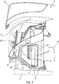
- FIGs 3 and 4 are perspective views of the cooling arrangement 11 in which the chassis and bonnet have been omitted. The difference between figure 3 and 4 is that in figure 4 an extended fan shroud 12 is shown.
- fan 5 is mounted on mounting plate 4 so that it is tilted towards the radiators 6.
- Fan 5 is secured to the fan mounting surface 8 by fan attachment means extending through bores in the plate 4.
- Radiators 6 are attached in series to plate 4 by bolt means. The radiators 6 are in a spaced arrangement from the fan 5 with the fan mounting surface 8 at one end of the sloping surface 13 and the radiator mounting surfaces 9 at the other end.
- the extended fan shroud is assembled from a number of parts bolted together.
- the extended shroud comprises at least three or four parts.
- the extended fan shroud 12 is shown having a lower part 12a which extends from the bottom half of a fan ring 12c in a forward direction with respect to the forward direction of travel of the tractor and an upper part 12b which extends rearwards from the upper half of the fan ring 12c towards the radiators 6 over plate 4.
- the upper part 12b is formed by two side parts 12d (only one is shown in figure 4 ) and a central part 12e. Side parts 12d may therefore be connected to either side of central part 12e to from an upper part 12b.
- central part 12e could itself comprise two half parts, each of which is connected to a side part 12e to form the upper part 12b.
- a flange 15 is provided with sealing means 16.
- the flange 15 extends from a lower part of the fan shroud 12a diagonally along opposing sides of the upper part 12b and across parts 12b and 12d of upper part 12b.
- the bonnet 2 may be provided with sealing means 16.
- Sealing means 16 may, for example comprise rubber tubing.
- the cooling arrangement 11 comprises a fan 5 and radiators 6 in which the radiators are located downstream of the fan. It is envisaged that the fan 5 and the radiators 6 could be arranged the other way around so that the radiators are mounted upstream of the fan. In such an arrangement, the radiators are mounted in front of the fan with respect to the forward direction of travel.
- a first air compartment C and a second air compartment D are defined.
- First air compartment C is partially positioned above cooling fan 5, between the grill 3 of hood 2a and extended fan shroud 12.
- Compartment C is a low pressure area.
- the dotted line in Figure 2 and 4 represents the grill 3 of the bonnet 2 when closed.
- grill 3 is formed in the hood 2a so that it has a vertical, or generally vertical part 3a and a generally horizontal part 3b. Grill part 3b extends from grill part 3a towards the rear of the vehicle past fan 5.
- Second air compartment D is positioned downstream of the fan 5 and as shown herein is located behind the radiators 6.
- Compartment D is a high pressure area and is enclosed by the hood 2a, the flange 15 and bonnet side panels 6b, 6c. Air which passes through the radiators 6 enters compartment D and then flows out to the atmosphere through a grill mounted in panel 6c, or through the frames 7.
- compartment it is meant a partially or fully enclosed area in which a surface which fully or partially encloses the area may, or may not be airtight.
- the panels 6a form an extension of the fan shroud between lower part 12a and upper part 12b so that air is channelled between the upper part 12b, side panels 6a and mounting plate 4 to the radiator 6.
- a complete fan shroud which extends from the fan to the radiator is formed from the upper part 12b, side panels 6a and plate 4.
- the mounting plate 4 guides air directly to the radiators 6.
Landscapes
- Engineering & Computer Science (AREA)
- Mechanical Engineering (AREA)
- Chemical & Material Sciences (AREA)
- Combustion & Propulsion (AREA)
- Transportation (AREA)
- Life Sciences & Earth Sciences (AREA)
- General Engineering & Computer Science (AREA)
- Soil Sciences (AREA)
- Environmental Sciences (AREA)
- Cooling, Air Intake And Gas Exhaust, And Fuel Tank Arrangements In Propulsion Units (AREA)
Description
- The invention relates to an engine cooling system on an agricultural vehicle, more specifically the invention relates to a fan shroud of the cooling system on the vehicle.
- Agricultural vehicles, such as agricultural tractors require a number of radiators in order to cool working media, such as a water cooler for the engine, a transmission oil cooler, a hydraulic oil cooler, an intercooler and possibly a condenser for an air-conditioning system. It is common practice to arrange the radiators in series one after the other under the vehicle bonnet so that air from a fan positioned at the front of the vehicle drives air through the radiators. Radiators in this arrangement may result in a high resistance to air flow which can necessitate a larger fan, or can interrupt the air flow resulting in the radiator overheating.
- To concentrate the flow of air from the fan to the first radiator, that is the first radiator downstream of the fan, the fan is usually provided with a fan shroud which projects in a direction towards the radiators. The fan shroud typically borders the circumference of the fan and extends a short distance parallel or substantially parallel to the longitudinal axis of the vehicle. With this arrangement, the fan shroud can be ineffective since there is a gap between the fan shroud and the radiator.
- Moreover, in order to conduct maintenance or cleaning of the area between the fan shroud and the radiator of such cooling arrangements, the whole bonnet hood must firstly be removed or lifted which can be inconvenient as not all parts of the bonnet may be moveable. Secondly the fan shroud must be removed.
-
EP 2 522 826 -
US 2005/211483 discloses a plenum cooling compartment through which ambient air flows. The plenum comprises a baffle, a floor, a top door, a front door and at least one side door. The fan and its shroud is located in the front door and therefore the fan shroud is encased by the frame of the door and the side doors do not come into contact with the shroud. Moreover, the fan draws air through the side doors into the plenum via the perforations, so that the air moves transverse to the longitudinal axis of the vehicle between the fan and cooling system. -
WO 2011/007235 discloses a fan and a cooling assembly inside an enclosure. The enclosure comprises a pair of side walls that each include a frame and a door mounted on the frame. The side walls and bottom wall serve to direct the air stream from the inlets along through the plenum and to the outlet opening. However, the enclosure is placed within the hood and the walls and the door are within the forward pan and therefore do not from part of the hood. -
US2002/017408 discloses a radiator, a fan and an engine arranged sequentially from the front of the vehicle under a hood. The fan draws air through the side vents of the hood so that the air flows transversely under the hood. The hood doses not therefore function as a shroud. Drip member is attached to the centre part of the hood and prevents water hitting the fan belt. It does not direct air from the fan to the cooling system since the fan is positioned downstream of the air flow. -
US 2004/262061 discloses a radiator and a fan ordered sequentially from the front of the vehicle. Air is drawn through vents in the side of the hood so that the air flows transversely under the hood and side panels do not form a shroud guiding air from the fan to the radiator. - It is an object of the present invention to provide an engine cooling system which is effective and which is easily accessible. It is a further object of the invention to provide an improved fan shroud on an agricultural vehicle engine cooling system.
- According to the invention there is provided an agricultural vehicle having a cooling system comprising a fan and a radiator mounted on a mounting plate, said fan provided with an upper shroud part which extends rearwards from the upper half of the fan towards the radiator over the plate, said cooling system housed in a bonnet of the vehicle, characterised in that the fan includes a fan ring, and the cooling system has a complete fan shroud formed by the upper shroud part, two removable side panels and the mounting plate wherein the complete fan shroud extends from the fan to the radiator to direct air between the fan and the radiator in a direction parallel or substantially parallel to the longitudinal axis of the vehicle. With this arrangement, part of the fan shroud extends up to a first radiator and thus can guide the air directly to the first radiator without the need for extra parts.
- Further, the fan and area between the fan and radiator is easily accessible without the need for removing or lifting the whole bonnet and the cooling system can be accessed from either, or both sides of the bonnet. Also, when the bonnet is closed the mounting plate, side panels of the bonnet and an upper part of the fan shroud are all connected so that all the air from the fan is directed to the first radiator.
- Preferably, the bonnet and/or side panel is provided with sealing means to prevent loss of air to the atmosphere. In this regard, as much air as possible is driven from the fan to the first radiator.
- More preferably, the fan is provided with an extended fan shroud which is connectable to the side panel of the bonnet to form part of the fan shroud. When closed, the side panel of the bonnet assist in guiding the air from the fan towards the rear of the vehicle.
- An agricultural tractor will now be described, by way of example only, with reference to the following drawings in which:
-
Figure 1 is a side view of an agricultural tractor with the bonnet closed, -
Figure 1 a is a perspective view of the bonnet offigure 1 , -
Figure 1b is a side view of the bonnet offigure 1a with a hood of the bonnet raised in which a cooling arrangement is shown, -
Figure 2 is a side view of a front part of the tractor bonnet offigure 1b , and -
Figures 3 and4 are perspective views of the cooling arrangement offigure 2 in which the bonnet panels and chassis are removed, and -
Figure 5 shows a cross section along line X-X offigure 4 which shows the cooling arrangement, and -
Figure 6 shows a detailed view of the front of the vehicle offigure 4 . -
Figure 1 is a side view of an agricultural tractor 1 having afront bonnet 2 which houses an engine and a cooling arrangement (not seen). Thebonnet 2 extends from a driver's cab 1a to the front of the tractor. A grill ormesh 3 is positioned at the front of the bonnet through which air passes and enters the cooling arrangement shown infigures 2 ,3 and4 . The tractor has a longitudinal axis extending along the length of the tractor passing through the mid points of a front and rear axle positioned transverse to the longitudinal axis. The arrow indicates the forward direction of travel. -
Figure 1a is a perspective view of the bonnet offigure 1 . Thebonnet 2 comprises ahood 2a and twoopposing side parts 2b. When thebonnet 2 is closed as shown infigures 1 and1a , thehood 2a has a fairly flat upper surface which extends in a generally horizontal manner from the cab. Towards the front of the vehicle, the upper surface of thehood 2a starts to slope downwards and has an almost vertical front part at the front of the tractor. Thehood 2a has an overhang which extends a small vertical distance along each of the two long opposing side edges. Each side of thebonnet 2 is formed from aside part 2b and the overhang ofhood 2a. The front part of thehood 2a and a part of the upper surface of the hood is provided with the grill ormesh 3. -
Figure 1b is a side view of thebonnet 2 with thehood 2a in an open position. Thehood 2a may be lifted to give access to the parts under it by pivoting it about a pivot axis located close to the cab 1a. When thehood 2a is lifted, it moves away from theside parts 2b. The larger the tractor, the higher is the front of the hood when pivoted open. In the open position, the hood is often too high for person to reach and then apply the necessary force to pivot it down to close it. The bonnet hood may be provided with aretractable belt 18 which extends between a spring mounted roller and an attaching means. Either one of the roller or attaching means is positioned on thehood 2a with the other part, attaching means or roller being positioned on the tractor, for example the chassis. When thehood 2a is open the belt extends vertically from thehood 2a to the chassis. To close the hood, the driver simply pulls a mid portion of the belt towards him or her which causes the hood to pivot downwards. As thehood 2a is closed, the belt retracts in length by the roller rolling the belt under tension from the roller spring. - As shown in
figure 6 , the front of the hood is provided with a locking means 50 for securing the hood to a front part of the tractor in a closed position. Additionally, or alternatively for easy closure of the hood and to prevent damage to the hood, guidance means is provided comprising tworollers 52 and twotracks 53. Infigure 6 , the hood is provided with tworollers 52 either side of the locking means 50.Tracks 53 extend in a substantially upright manner from a front part of the tractor which enables therollers 52 to roll between thetracks 53 and guide the locking means 50 to the front of the tractor for engagement as the hood is lowered. - Each
side part 2b comprisesmoveable side panels Side panels 6a are located towards the front of the tractor and extend approximately from afan 5 toradiators 6 as shown infigure 3 . If more than oneradiator 6 is fitted, the radiators are usually mounted in a series becoming increasingly closer towards the engine.Panels Moveable side panels side part 2b so that they can be moved with respect to the side parts to give access to components of the cooling system and/or engine system under the bonnet. The pivoting means may comprise spring means. Alternatively,side panels side parts 2b to give access. - The edges of the
panels side parts 2b into whichpanels Fig. 2 ) to prevent the escape of air to the atmosphere. - If
side panel 6a is removable, it is attached to sidepart 2b by clamps and hooks at the locations marked E infigures 1a and1b . To enable theside panels 6a to be easily removed, ahand grip 17 can be provided on theside panels 6a which allows a person to easily get a grip of the panels. -
Figure 2 is a side view of a front part of thebonnet 2 in which theside panel 6a has been omitted so that the cooling arrangement inside the bonnet can be seen. A mountingplate 4 is provided which extends from under thefan 5 which is positioned at the front of the tractor behind thegrill 3 to under the radiator orradiators 6 which are positioned in front of the engine (not shown) with respect to the forward direction of travel of the tractor. The tractor is provided with two parallel frames 7 which form the chassis. The mountingplate 4 extends widthways across both frames 7 and is provided with afan mounting surface 8 and radiator mounting surfaces 9. The side profile of the mountingplate 4 is that of a laterally extended Z in that thefan mounting surface 8 andradiator mounting surfaces 9 are generally horizontal and are connected by a slopingsurface 13 such that the fan mounting surface is elevated with respect to the radiator mounting surfaces. Since the frames 7 are horizontal, asupport element 10 fixes the front of theplate 4 under thefan mounting surface 8 to the frames 7. Thesupport element 10 is affixed to the frames 7 by bolts. Theradiator mounting surface 9 of the plate is secured directly to the frames 7 by bolt means. On the underside of theplate 4 at the area of thefan mounting surface 8, attachment means are provided for attaching a light or heater core thereto. In, or on theplate 4 at the area of theradiator mounting surface 9, bore holes and/or channels are provided for receiving pipes from the radiator orradiators 6 and/or delivering liquid to the radiator orradiators 6. - Two air flows are indicated by arrows A and B. Air Arrow A shows an air flow for an air intake for the combustion of the engine and arrow B for cooling the
radiators 6 and the engine. Thefan 5 pushes air through theradiators 6 and the engine. -
Figures 3 and4 are perspective views of thecooling arrangement 11 in which the chassis and bonnet have been omitted. The difference betweenfigure 3 and4 is that infigure 4 anextended fan shroud 12 is shown. As shown infigures 3 and4 fan 5 is mounted on mountingplate 4 so that it is tilted towards theradiators 6.Fan 5 is secured to thefan mounting surface 8 by fan attachment means extending through bores in theplate 4.Radiators 6 are attached in series toplate 4 by bolt means. Theradiators 6 are in a spaced arrangement from thefan 5 with thefan mounting surface 8 at one end of the slopingsurface 13 and theradiator mounting surfaces 9 at the other end. - The extended fan shroud is assembled from a number of parts bolted together. Preferably, the extended shroud comprises at least three or four parts. In
figure 4 theextended fan shroud 12 is shown having a lower part 12a which extends from the bottom half of a fan ring 12c in a forward direction with respect to the forward direction of travel of the tractor and an upper part 12b which extends rearwards from the upper half of the fan ring 12c towards theradiators 6 overplate 4. The upper part 12b is formed by twoside parts 12d (only one is shown infigure 4 ) and acentral part 12e.Side parts 12d may therefore be connected to either side ofcentral part 12e to from an upper part 12b. Alternatively,central part 12e could itself comprise two half parts, each of which is connected to aside part 12e to form the upper part 12b. - A
flange 15 is provided with sealing means 16. Theflange 15 extends from a lower part of the fan shroud 12a diagonally along opposing sides of the upper part 12b and acrossparts 12b and 12d of upper part 12b. Preferably thebonnet 2 may be provided with sealing means 16. Sealing means 16 may, for example comprise rubber tubing. - In
Figure 5 thecooling arrangement 11 is shown. The cooling arrangement shown comprises afan 5 andradiators 6 in which the radiators are located downstream of the fan. It is envisaged that thefan 5 and theradiators 6 could be arranged the other way around so that the radiators are mounted upstream of the fan. In such an arrangement, the radiators are mounted in front of the fan with respect to the forward direction of travel. - When the
bonnet 2 is closed and in contact with the sealing means 16 two air compartments are defined. A first air compartment C and a second air compartment D. First air compartment C is partially positioned above coolingfan 5, between thegrill 3 ofhood 2a andextended fan shroud 12. Compartment C is a low pressure area. The dotted line inFigure 2 and4 represents thegrill 3 of thebonnet 2 when closed. With reference tofigure 1a in which the bonnet is closed,grill 3 is formed in thehood 2a so that it has a vertical, or generallyvertical part 3a and a generallyhorizontal part 3b. Grillpart 3b extends fromgrill part 3a towards the rear of the vehicle pastfan 5. - Second air compartment D is positioned downstream of the
fan 5 and as shown herein is located behind theradiators 6. Compartment D is a high pressure area and is enclosed by thehood 2a, theflange 15 andbonnet side panels radiators 6 enters compartment D and then flows out to the atmosphere through a grill mounted inpanel 6c, or through the frames 7. - By compartment it is meant a partially or fully enclosed area in which a surface which fully or partially encloses the area may, or may not be airtight.
- When the
bonnet 2 is closed and sealed, thepanels 6a form an extension of the fan shroud between lower part 12a and upper part 12b so that air is channelled between the upper part 12b,side panels 6a and mountingplate 4 to theradiator 6. As a result, a complete fan shroud which extends from the fan to the radiator is formed from the upper part 12b,side panels 6a andplate 4. Thereby the mountingplate 4 guides air directly to theradiators 6. - When the
bonnet 2 is closed and the sealing means 16 contacts the bonnet 2 (or flange) two air compartments C and D are defined.
Claims (3)
- An agricultural vehicle (1) having a cooling system comprising a fan (5) and a radiator (6) mounted on a mounting plate (4), said fan (5) provided with an upper shroud part (12b) which extends rearwards from the upper half of the fan (5) towards the radiator (6) over the plate (4),said cooling system housed in a bonnet (2) of the vehicle (1), characterised in that the fan (5) includes a fan ring (12c), and the cooling system has a complete fan shroud formed by the fan ring (12c), the upper shroud part (12b), two removable side panels (6a) and the mounting plate (4) wherein the complete fan shroud extends from the fan (5) to the radiator (6) to direct air between the fan (5) and the radiator (6) in a direction parallel or substantially parallel to the longitudinal axis of the vehicle.
- An agricultural vehicle as claimed in claim 1 wherein the side panels (6a) are provided with sealing means (14) to prevent loss of air to the atmosphere.
- An agricultural vehicle as claimed in claim 1 wherein the complete fan shroud further includes a lower shroud part (12a) extending in a forward direction from the bottom half of the fan ring (12c) forming an extended fan shroud.
Applications Claiming Priority (2)
| Application Number | Priority Date | Filing Date | Title |
|---|---|---|---|
| GB201312943A GB201312943D0 (en) | 2013-07-19 | 2013-07-19 | Fan Shroud on an Agricultural Vehicle |
| PCT/EP2014/065620 WO2015007914A1 (en) | 2013-07-19 | 2014-07-21 | Fan shroud on an agricultural vehicle |
Publications (2)
| Publication Number | Publication Date |
|---|---|
| EP3022416A1 EP3022416A1 (en) | 2016-05-25 |
| EP3022416B1 true EP3022416B1 (en) | 2021-03-31 |
Family
ID=49118987
Family Applications (1)
| Application Number | Title | Priority Date | Filing Date |
|---|---|---|---|
| EP14746983.7A Active EP3022416B1 (en) | 2013-07-19 | 2014-07-21 | Fan shroud on an agricultural vehicle |
Country Status (4)
| Country | Link |
|---|---|
| US (1) | US9561717B2 (en) |
| EP (1) | EP3022416B1 (en) |
| GB (1) | GB201312943D0 (en) |
| WO (1) | WO2015007914A1 (en) |
Families Citing this family (7)
| Publication number | Priority date | Publication date | Assignee | Title |
|---|---|---|---|---|
| GB201615151D0 (en) | 2016-09-07 | 2016-10-19 | Agco Int Gmbh | Vehicle tank |
| CN108513553B (en) * | 2016-12-28 | 2022-03-29 | 株式会社小松制作所 | Working vehicle |
| FR3062600B1 (en) * | 2017-02-06 | 2020-06-12 | Valeo Systemes Thermiques | COOLING UNIT FOR ENGINE COMPARTMENT |
| US10086878B2 (en) * | 2017-02-09 | 2018-10-02 | Cnh Industrial America Llc | Hood guiding system for a work vehicle |
| US20240191467A1 (en) | 2022-12-12 | 2024-06-13 | Great Plains Manufacturing, Inc. | Tilting cab for work machine |
| USD1047301S1 (en) * | 2023-04-10 | 2024-10-15 | Munters Corporation | Dark-out box for agricultural ventilation |
| JP2025110653A (en) * | 2024-01-16 | 2025-07-29 | 株式会社クボタ | Work vehicle |
Family Cites Families (11)
| Publication number | Priority date | Publication date | Assignee | Title |
|---|---|---|---|---|
| JP3446475B2 (en) | 1996-05-21 | 2003-09-16 | 日産自動車株式会社 | Structure of air duct for introducing outside air in vehicles |
| JP2000062474A (en) * | 1998-08-21 | 2000-02-29 | Komatsu Ltd | Work vehicle cooling system |
| JP2002021565A (en) * | 2000-07-11 | 2002-01-23 | Komatsu Ltd | Construction vehicle engine enclosure |
| ITTO20030127A1 (en) * | 2003-02-21 | 2004-08-22 | Same Deutz Fahr Group Spa | COOLING SYSTEM FOR AN AGRICULTURAL MACHINE. |
| US20040262061A1 (en) * | 2003-06-25 | 2004-12-30 | Case, Llc | Work vehicle hood |
| US7204329B2 (en) | 2004-03-24 | 2007-04-17 | Deere & Company | Under-hood engine air intake system |
| US7418994B2 (en) | 2004-06-11 | 2008-09-02 | Deere & Company | Fan shroud with integral hood seal |
| US8182217B2 (en) * | 2007-03-30 | 2012-05-22 | Denso International America, Inc. | Mechanical fan sub-shroud attachment feature, molded plastic snap feature |
| US8167067B2 (en) * | 2009-07-16 | 2012-05-01 | Agco Corporation | Agricultural vehicle emission aftertreatment device utilizing heat exchanger ventilation |
| US8347994B2 (en) * | 2011-04-13 | 2013-01-08 | Deere & Company | Tractor hood airflow system |
| CN202965935U (en) | 2012-07-02 | 2013-06-05 | 广西柳工机械股份有限公司 | Construction machinery cooling system |
-
2013
- 2013-07-19 GB GB201312943A patent/GB201312943D0/en not_active Ceased
-
2014
- 2014-07-21 US US14/995,378 patent/US9561717B2/en active Active
- 2014-07-21 EP EP14746983.7A patent/EP3022416B1/en active Active
- 2014-07-21 WO PCT/EP2014/065620 patent/WO2015007914A1/en not_active Ceased
Non-Patent Citations (1)
| Title |
|---|
| None * |
Also Published As
| Publication number | Publication date |
|---|---|
| EP3022416A1 (en) | 2016-05-25 |
| US20160193910A1 (en) | 2016-07-07 |
| WO2015007914A1 (en) | 2015-01-22 |
| GB201312943D0 (en) | 2013-09-04 |
| US9561717B2 (en) | 2017-02-07 |
Similar Documents
| Publication | Publication Date | Title |
|---|---|---|
| US9561717B2 (en) | Fan shroud on an agricultural vehicle | |
| US7913505B2 (en) | Air conditioning device for work vehicle | |
| US8544582B2 (en) | Utility vehicle | |
| US4071009A (en) | Combined noise suppressing and air flow guide enclosure for engines | |
| CA2687854C (en) | Use of fan shroud to ventilate engine compartment | |
| EP2022671A1 (en) | Heated cab entry steps | |
| EP2522826A2 (en) | Tractor hood airflow system | |
| KR101978661B1 (en) | Working vehicle | |
| JP2014019358A (en) | Service car | |
| US9676271B1 (en) | Vehicle cooling arrangement | |
| US9657456B2 (en) | Wheel loader | |
| JP3329715B2 (en) | Tractor | |
| US8820453B2 (en) | Bumper assembly | |
| EP3022080B1 (en) | Vehicle cooling arrangement | |
| KR101709365B1 (en) | Construction Machine | |
| US20060016632A1 (en) | Lawn mower having an engine disposed rearwardly of a driver's seat | |
| WO2016012030A1 (en) | Cooling arrangement on an agricultural vehicle | |
| JP5846878B2 (en) | Air circulation device | |
| EP3798103B1 (en) | Work vehicle | |
| JP5681584B2 (en) | Working vehicle hood opening and closing structure | |
| JP3735012B2 (en) | Construction machinery | |
| EP1098073A2 (en) | Motor vehicle having an oil cooler | |
| US6712690B1 (en) | Portable ventilating system | |
| JP3623918B2 (en) | Cooling air flow device for traveling vehicle | |
| JPWO2004099581A1 (en) | Cooling device for work vehicle |
Legal Events
| Date | Code | Title | Description |
|---|---|---|---|
| PUAI | Public reference made under article 153(3) epc to a published international application that has entered the european phase |
Free format text: ORIGINAL CODE: 0009012 |
|
| 17P | Request for examination filed |
Effective date: 20160219 |
|
| AK | Designated contracting states |
Kind code of ref document: A1 Designated state(s): AL AT BE BG CH CY CZ DE DK EE ES FI FR GB GR HR HU IE IS IT LI LT LU LV MC MK MT NL NO PL PT RO RS SE SI SK SM TR |
|
| AX | Request for extension of the european patent |
Extension state: BA ME |
|
| RIN1 | Information on inventor provided before grant (corrected) |
Inventor name: WEIGAND JAN Inventor name: MAIER, THOMAS Inventor name: BARZEN, ALEXANDER Inventor name: OPITZ, MARCO Inventor name: JUTZ, GEORG Inventor name: KOLMER HARTMUT Inventor name: FREYTAG ERICH |
|
| DAX | Request for extension of the european patent (deleted) | ||
| STAA | Information on the status of an ep patent application or granted ep patent |
Free format text: STATUS: EXAMINATION IS IN PROGRESS |
|
| 17Q | First examination report despatched |
Effective date: 20170616 |
|
| GRAP | Despatch of communication of intention to grant a patent |
Free format text: ORIGINAL CODE: EPIDOSNIGR1 |
|
| STAA | Information on the status of an ep patent application or granted ep patent |
Free format text: STATUS: GRANT OF PATENT IS INTENDED |
|
| RIC1 | Information provided on ipc code assigned before grant |
Ipc: F01P 5/06 20060101AFI20201009BHEP Ipc: F01P 11/10 20060101ALN20201009BHEP Ipc: B62D 25/10 20060101ALI20201009BHEP Ipc: B60K 11/04 20060101ALI20201009BHEP |
|
| INTG | Intention to grant announced |
Effective date: 20201118 |
|
| GRAS | Grant fee paid |
Free format text: ORIGINAL CODE: EPIDOSNIGR3 |
|
| GRAA | (expected) grant |
Free format text: ORIGINAL CODE: 0009210 |
|
| STAA | Information on the status of an ep patent application or granted ep patent |
Free format text: STATUS: THE PATENT HAS BEEN GRANTED |
|
| AK | Designated contracting states |
Kind code of ref document: B1 Designated state(s): AL AT BE BG CH CY CZ DE DK EE ES FI FR GB GR HR HU IE IS IT LI LT LU LV MC MK MT NL NO PL PT RO RS SE SI SK SM TR |
|
| REG | Reference to a national code |
Ref country code: GB Ref legal event code: FG4D Ref country code: CH Ref legal event code: EP |
|
| REG | Reference to a national code |
Ref country code: AT Ref legal event code: REF Ref document number: 1377177 Country of ref document: AT Kind code of ref document: T Effective date: 20210415 |
|
| REG | Reference to a national code |
Ref country code: DE Ref legal event code: R096 Ref document number: 602014076154 Country of ref document: DE |
|
| REG | Reference to a national code |
Ref country code: IE Ref legal event code: FG4D |
|
| REG | Reference to a national code |
Ref country code: LT Ref legal event code: MG9D |
|
| PG25 | Lapsed in a contracting state [announced via postgrant information from national office to epo] |
Ref country code: NO Free format text: LAPSE BECAUSE OF FAILURE TO SUBMIT A TRANSLATION OF THE DESCRIPTION OR TO PAY THE FEE WITHIN THE PRESCRIBED TIME-LIMIT Effective date: 20210630 Ref country code: BG Free format text: LAPSE BECAUSE OF FAILURE TO SUBMIT A TRANSLATION OF THE DESCRIPTION OR TO PAY THE FEE WITHIN THE PRESCRIBED TIME-LIMIT Effective date: 20210630 Ref country code: FI Free format text: LAPSE BECAUSE OF FAILURE TO SUBMIT A TRANSLATION OF THE DESCRIPTION OR TO PAY THE FEE WITHIN THE PRESCRIBED TIME-LIMIT Effective date: 20210331 Ref country code: HR Free format text: LAPSE BECAUSE OF FAILURE TO SUBMIT A TRANSLATION OF THE DESCRIPTION OR TO PAY THE FEE WITHIN THE PRESCRIBED TIME-LIMIT Effective date: 20210331 |
|
| PG25 | Lapsed in a contracting state [announced via postgrant information from national office to epo] |
Ref country code: RS Free format text: LAPSE BECAUSE OF FAILURE TO SUBMIT A TRANSLATION OF THE DESCRIPTION OR TO PAY THE FEE WITHIN THE PRESCRIBED TIME-LIMIT Effective date: 20210331 Ref country code: LV Free format text: LAPSE BECAUSE OF FAILURE TO SUBMIT A TRANSLATION OF THE DESCRIPTION OR TO PAY THE FEE WITHIN THE PRESCRIBED TIME-LIMIT Effective date: 20210331 Ref country code: SE Free format text: LAPSE BECAUSE OF FAILURE TO SUBMIT A TRANSLATION OF THE DESCRIPTION OR TO PAY THE FEE WITHIN THE PRESCRIBED TIME-LIMIT Effective date: 20210331 |
|
| REG | Reference to a national code |
Ref country code: NL Ref legal event code: MP Effective date: 20210331 |
|
| REG | Reference to a national code |
Ref country code: AT Ref legal event code: MK05 Ref document number: 1377177 Country of ref document: AT Kind code of ref document: T Effective date: 20210331 |
|
| PG25 | Lapsed in a contracting state [announced via postgrant information from national office to epo] |
Ref country code: SM Free format text: LAPSE BECAUSE OF FAILURE TO SUBMIT A TRANSLATION OF THE DESCRIPTION OR TO PAY THE FEE WITHIN THE PRESCRIBED TIME-LIMIT Effective date: 20210331 Ref country code: LT Free format text: LAPSE BECAUSE OF FAILURE TO SUBMIT A TRANSLATION OF THE DESCRIPTION OR TO PAY THE FEE WITHIN THE PRESCRIBED TIME-LIMIT Effective date: 20210331 Ref country code: NL Free format text: LAPSE BECAUSE OF FAILURE TO SUBMIT A TRANSLATION OF THE DESCRIPTION OR TO PAY THE FEE WITHIN THE PRESCRIBED TIME-LIMIT Effective date: 20210331 Ref country code: EE Free format text: LAPSE BECAUSE OF FAILURE TO SUBMIT A TRANSLATION OF THE DESCRIPTION OR TO PAY THE FEE WITHIN THE PRESCRIBED TIME-LIMIT Effective date: 20210331 Ref country code: CZ Free format text: LAPSE BECAUSE OF FAILURE TO SUBMIT A TRANSLATION OF THE DESCRIPTION OR TO PAY THE FEE WITHIN THE PRESCRIBED TIME-LIMIT Effective date: 20210331 Ref country code: AT Free format text: LAPSE BECAUSE OF FAILURE TO SUBMIT A TRANSLATION OF THE DESCRIPTION OR TO PAY THE FEE WITHIN THE PRESCRIBED TIME-LIMIT Effective date: 20210331 |
|
| PG25 | Lapsed in a contracting state [announced via postgrant information from national office to epo] |
Ref country code: IS Free format text: LAPSE BECAUSE OF FAILURE TO SUBMIT A TRANSLATION OF THE DESCRIPTION OR TO PAY THE FEE WITHIN THE PRESCRIBED TIME-LIMIT Effective date: 20210731 Ref country code: ES Free format text: LAPSE BECAUSE OF FAILURE TO SUBMIT A TRANSLATION OF THE DESCRIPTION OR TO PAY THE FEE WITHIN THE PRESCRIBED TIME-LIMIT Effective date: 20210331 Ref country code: PT Free format text: LAPSE BECAUSE OF FAILURE TO SUBMIT A TRANSLATION OF THE DESCRIPTION OR TO PAY THE FEE WITHIN THE PRESCRIBED TIME-LIMIT Effective date: 20210802 Ref country code: PL Free format text: LAPSE BECAUSE OF FAILURE TO SUBMIT A TRANSLATION OF THE DESCRIPTION OR TO PAY THE FEE WITHIN THE PRESCRIBED TIME-LIMIT Effective date: 20210331 Ref country code: RO Free format text: LAPSE BECAUSE OF FAILURE TO SUBMIT A TRANSLATION OF THE DESCRIPTION OR TO PAY THE FEE WITHIN THE PRESCRIBED TIME-LIMIT Effective date: 20210331 Ref country code: SK Free format text: LAPSE BECAUSE OF FAILURE TO SUBMIT A TRANSLATION OF THE DESCRIPTION OR TO PAY THE FEE WITHIN THE PRESCRIBED TIME-LIMIT Effective date: 20210331 |
|
| REG | Reference to a national code |
Ref country code: DE Ref legal event code: R097 Ref document number: 602014076154 Country of ref document: DE |
|
| PG25 | Lapsed in a contracting state [announced via postgrant information from national office to epo] |
Ref country code: DK Free format text: LAPSE BECAUSE OF FAILURE TO SUBMIT A TRANSLATION OF THE DESCRIPTION OR TO PAY THE FEE WITHIN THE PRESCRIBED TIME-LIMIT Effective date: 20210331 Ref country code: AL Free format text: LAPSE BECAUSE OF FAILURE TO SUBMIT A TRANSLATION OF THE DESCRIPTION OR TO PAY THE FEE WITHIN THE PRESCRIBED TIME-LIMIT Effective date: 20210331 |
|
| PLBE | No opposition filed within time limit |
Free format text: ORIGINAL CODE: 0009261 |
|
| STAA | Information on the status of an ep patent application or granted ep patent |
Free format text: STATUS: NO OPPOSITION FILED WITHIN TIME LIMIT |
|
| REG | Reference to a national code |
Ref country code: CH Ref legal event code: PL |
|
| 26N | No opposition filed |
Effective date: 20220104 |
|
| GBPC | Gb: european patent ceased through non-payment of renewal fee |
Effective date: 20210721 |
|
| PG25 | Lapsed in a contracting state [announced via postgrant information from national office to epo] |
Ref country code: MC Free format text: LAPSE BECAUSE OF FAILURE TO SUBMIT A TRANSLATION OF THE DESCRIPTION OR TO PAY THE FEE WITHIN THE PRESCRIBED TIME-LIMIT Effective date: 20210331 |
|
| REG | Reference to a national code |
Ref country code: BE Ref legal event code: MM Effective date: 20210731 |
|
| PG25 | Lapsed in a contracting state [announced via postgrant information from national office to epo] |
Ref country code: LI Free format text: LAPSE BECAUSE OF NON-PAYMENT OF DUE FEES Effective date: 20210731 Ref country code: GB Free format text: LAPSE BECAUSE OF NON-PAYMENT OF DUE FEES Effective date: 20210721 Ref country code: CH Free format text: LAPSE BECAUSE OF NON-PAYMENT OF DUE FEES Effective date: 20210731 |
|
| PG25 | Lapsed in a contracting state [announced via postgrant information from national office to epo] |
Ref country code: IS Free format text: LAPSE BECAUSE OF FAILURE TO SUBMIT A TRANSLATION OF THE DESCRIPTION OR TO PAY THE FEE WITHIN THE PRESCRIBED TIME-LIMIT Effective date: 20210731 Ref country code: LU Free format text: LAPSE BECAUSE OF NON-PAYMENT OF DUE FEES Effective date: 20210721 |
|
| PG25 | Lapsed in a contracting state [announced via postgrant information from national office to epo] |
Ref country code: IE Free format text: LAPSE BECAUSE OF NON-PAYMENT OF DUE FEES Effective date: 20210721 Ref country code: BE Free format text: LAPSE BECAUSE OF NON-PAYMENT OF DUE FEES Effective date: 20210731 |
|
| PG25 | Lapsed in a contracting state [announced via postgrant information from national office to epo] |
Ref country code: HU Free format text: LAPSE BECAUSE OF FAILURE TO SUBMIT A TRANSLATION OF THE DESCRIPTION OR TO PAY THE FEE WITHIN THE PRESCRIBED TIME-LIMIT; INVALID AB INITIO Effective date: 20140721 |
|
| P01 | Opt-out of the competence of the unified patent court (upc) registered |
Effective date: 20230518 |
|
| PG25 | Lapsed in a contracting state [announced via postgrant information from national office to epo] |
Ref country code: CY Free format text: LAPSE BECAUSE OF FAILURE TO SUBMIT A TRANSLATION OF THE DESCRIPTION OR TO PAY THE FEE WITHIN THE PRESCRIBED TIME-LIMIT Effective date: 20210331 |
|
| PG25 | Lapsed in a contracting state [announced via postgrant information from national office to epo] |
Ref country code: GR Free format text: LAPSE BECAUSE OF FAILURE TO SUBMIT A TRANSLATION OF THE DESCRIPTION OR TO PAY THE FEE WITHIN THE PRESCRIBED TIME-LIMIT Effective date: 20210331 |
|
| PG25 | Lapsed in a contracting state [announced via postgrant information from national office to epo] |
Ref country code: MK Free format text: LAPSE BECAUSE OF FAILURE TO SUBMIT A TRANSLATION OF THE DESCRIPTION OR TO PAY THE FEE WITHIN THE PRESCRIBED TIME-LIMIT Effective date: 20210331 |
|
| PG25 | Lapsed in a contracting state [announced via postgrant information from national office to epo] |
Ref country code: TR Free format text: LAPSE BECAUSE OF FAILURE TO SUBMIT A TRANSLATION OF THE DESCRIPTION OR TO PAY THE FEE WITHIN THE PRESCRIBED TIME-LIMIT Effective date: 20210331 |
|
| PG25 | Lapsed in a contracting state [announced via postgrant information from national office to epo] |
Ref country code: MT Free format text: LAPSE BECAUSE OF FAILURE TO SUBMIT A TRANSLATION OF THE DESCRIPTION OR TO PAY THE FEE WITHIN THE PRESCRIBED TIME-LIMIT Effective date: 20210331 |
|
| PGFP | Annual fee paid to national office [announced via postgrant information from national office to epo] |
Ref country code: DE Payment date: 20250722 Year of fee payment: 12 |
|
| PGFP | Annual fee paid to national office [announced via postgrant information from national office to epo] |
Ref country code: IT Payment date: 20250722 Year of fee payment: 12 |
|
| PGFP | Annual fee paid to national office [announced via postgrant information from national office to epo] |
Ref country code: FR Payment date: 20250725 Year of fee payment: 12 |